

|

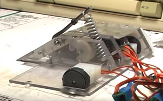
Privacy Policy Pneumatic flipper weapons are awesome but their complexity can be daunting, particularly in smaller combat robots. Flippers powered by mechanical energy stored in springs or elastic bands with electric gearmotors to trigger and reset spring flippers offer an attractive alternative. Several designs are outlined in Ask Aaron: Spring Flipper Designs. I've edited together posts from our Ask Aaron: Combat Robot Questions and Answers page into a reference for snail cam design and construction. Overview  The deceptively simple 'Snail Cam' mechanism has seen limited use in robot combat to date, and rarely outside the insect weight classes.
Advantages A properly designed snail cam will keep the torque load on the gearmotor constant thruout the reset cycle, resulting in a quicker reset time with less motor effort. The 'ready' point is a stable flat or detent on the cam that requires no motor torque to hold in place. The snail cam itself can be crafted from plastic using standard shop tools. Disadvantages Sliding friction between the cam and cam follower can be considerable. Crafting the cam from a low-friction plastic like UHMW polyethylene will keep this manageable, and a needle bearing cam follower can completely eliminate the problem. Resources Dale Hetherington's detailed build log for antweight 'Dead Air' fills in a lot of detail on design and constuction. Videos  This spring flipper mechanism from 'M & J Robotics' is a trial-and-error design. The builder says, "The cam shape is just something we adjusted till it worked."
You can hear the motor bog down under torque peaks as it winds the spring. It works, but it wastes a lot of the power and speed available from the motor.  'Jännä' is a 450 gram antweight robot by European YouTuber 'mikromekaanikko'.
The snail cam is well designed and operates at close to optimum performance. This compact and efficient mechanism wouild be a good starting point for your own flipper. Cam Profile  The load encountered when extending or compressing a spring increases linearly with distance. If it takes 10 pounds of force to compress a spring the first inch, the second inch will take 20 pounds, the third inch 30 pounds and so on: see Hooke's law.
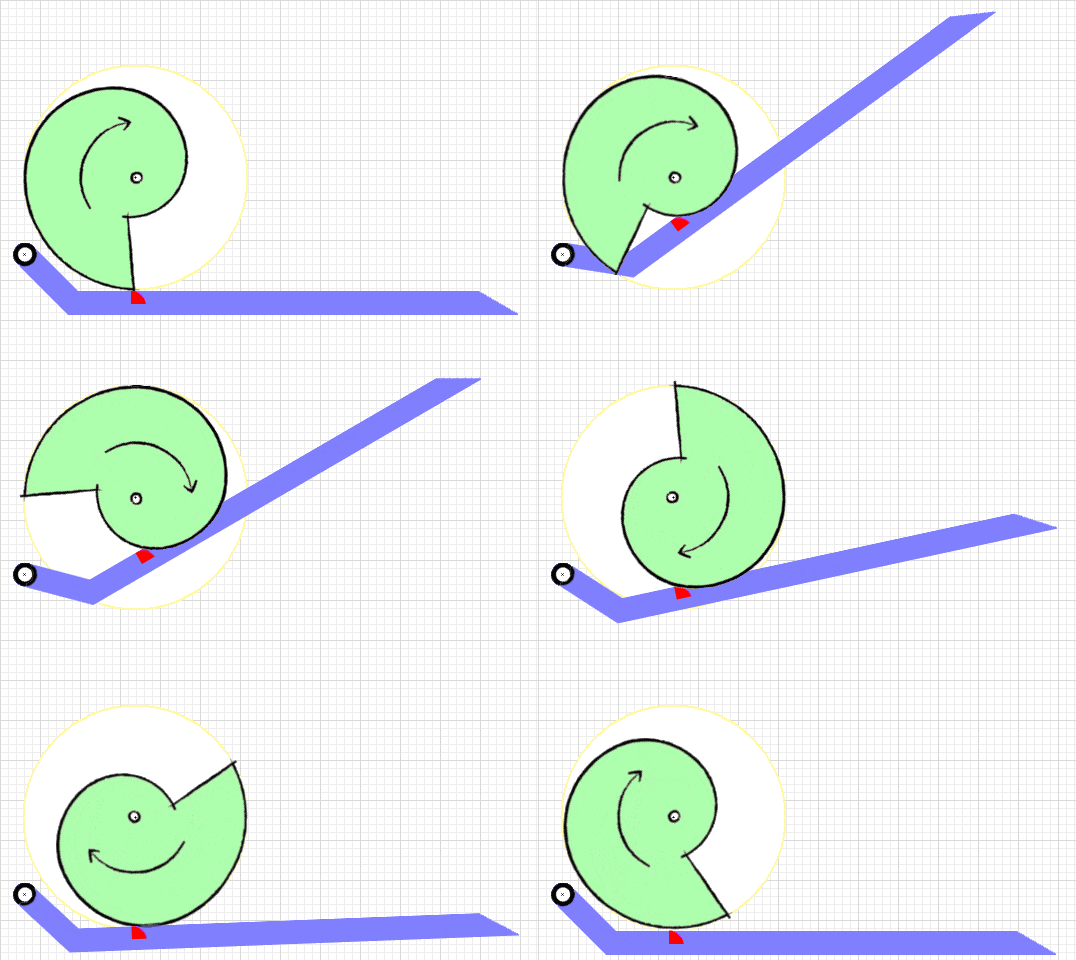
Using a simple Archimedean spiral cam profile will place a constantly increasing load on the motor powering the cam and cause it to slow as the cam reaches the final stages of spring loading. Gearing the cam motor to meet the high torque needed at the end of the load cycle slows the early part of the cam rotation, resulting in a slower than optimal reset time. The ideal profile for the 'snail cam' is a parabolic spiral that reduces the lift rate to match the increasing load imposed by the spring as it is extended. This profile keeps the motor speed constant for the entire cycle, resulting in improved cycle time and less strain on the cam motor. A mathematically perfect parabolic spiral is unfortunately poorly suited for use as a mechanical cam: the vertical drop immediately followed by a precipitous rise is neigh impossible for a mechanical cam follower to negotiate. The exact modifications to the profile will depend on the design of your mechanism. 'Jännä' has a lever-style follower and its cam is modified with a broad flat region pointing toward the lever hinge to provide a suitable landing for the follower and a rapid initial lift. It's important to get the shape of the parabolic spiral correct to even out the torque load on the motor. The spring becomes harder to compress as it compresses farther, so the cam has to provide a lot of compression at the start of rotation (50% the total is in the first 25% of rotation) and taper to less compression as the load increases (the last 12.5% takes the final 25% of rotation).
The formula for the parabolic spiral in polar coordinates is:
0 degrees rotation
(15 * 0.0527) * 0 0.5 + 5 = (0.79 * 0.0) + 5 = 5.0mm
90 degrees rotation
180 degrees rotation
270 degrees rotation
360 degrees rotation
I've created a 'Google Sheets' spreadsheet that will calculate and draw a snail cam profile similar to the pics below. The link requires you to sign-in to your Google account, then offers you a copy of the sheet:
Spring Force Requirement  How much spring force is required for an effective spring flipper? There are too many variables (force, stroke, geometry, angle, performance expectations...) to give a simple calculated result to that question. Further, the dynamics of a spring flipper are too different from the dynamics of a pneumatic flipper for the two systems to be directly compared. I suggest mocking up the weapon geometry in your workshop and experimenting with differing spring rates on a proxy opponent to find a satisfactory result.
Note If the spring 'pre-loads' the snail cam with some force at the minimum lift starting position, the parabolic spiral formula must change in order to keep the torque load on the cam motor constant. The Torque Requirement Now that we have a cam design that keeps the torque load on the gearmotor driving the cam close to constant and have selected a suitable spring, how do we calculate the torque requirement of the gearmotor? We can derive the required torque from the rotational work formula:
In our case the work is the extension of the spring, which takes place over the course of one revolution of the axle. The spring extension force is a linear function (Hooke's law), so we can calculate the average force required to extend the spring as follows:
That plugs into the basic linear work equation [Work = Force * Distance] like this:
Getting close now. One full rotation is 2𝜋 radians, so with a little algebra the rotational work formula transposes to our needed torque equation:
Example If you're extending a spring with a rate (at the cam) of 200 ounces per inch from its rest state (zero force) to one inch of extension (at the cam) with an optimized parabolic snail cam over one full rotation, the torque must exceed:
There are some losses due to angular inefficiencies and rubbing friction with the cam, and you will want the motor to deliver the required torque with enough speed to extend the spring quickly. I'd suggest a gearmotor with a stall torque about three times the formula result to avoid bogging and let the motor operate up near its power output peak.
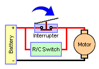
If you don't care to do the math to calculate the torque requirement for your snail cam motor, the same 'Google Sheets' spreadsheet mentioned in the 'Cam Profile' section above does that calculation for you. Here's the link again: Motor Control  To perform as a useful weapon the snail cam flipper motor should - at the press of a transmitter button or momentary switch - move the cam forward to fire the flipper and continue motion to reset the flipper. When reset is complete the flipper motor should then stop without operator intervention, ready for another flip command. How exactly do you make that happen?
When you turn off the windshield wipers on an automobile have you noticed how they continue for the rest of the wipe stroke and then stop in the park position? That's what you're looking for and here's how you do it:

Note A micro switch is simple, but you can certainly use other sensor types: infrared emitter/detector, inductive proximity, magnetic... whatever you're comfortable using.

Copyright 2019 by Mark Joerger -- all rights reserved. |