This page is one of several archives of 'Ask Aaron' questions and answers categorized by topic. To see the most recent questions or to ask a new question, go to the Ask Aaron Home Page.
Take a tour of posts in this Ask Aaron Archive that have been referenced to answer new questions. Click the 'Mystery Post Tour' button above to get started.
Take a look at this archived post about attacking TPU plastic with a 'low bite' weapon.
Speed, Drag, and Power
In my beetleweight eggbeater bot, the ESC for the weapon motor keeps giving overcurrent issues. At 1000 kv with a 14:21 reduction there was no overcurrent, but we want to do an 1800kv for higher RPMs and at different gear reductions we keep getting overcurrent issues. We think it might be a mechanical issue but we're not sure. What are some solutions to this? [Edison, New Jersey]
A: Mark J. Eggbeater weapons notoriously create a lot of aerodynamic drag. Assuming that you keep the 14:21 reduction:
The power needed to overcome aero drag increases with the cube of speed.
Increasing the weapon speed by [1800/1000 = ] 1.8 times will require [1.83 = ] 5.8 times the power.
For a given motor, the 1800 Kv version will provide more power than the 1000 Kv version -- but not 5.8 times as much.
Attempting to spin the beater at such a high speed, the 1800 Kv weapon motor will bog down and pull great gobs of current.
You aren't specifying the "different gear reductions" you are trying, but you're going to need considerably greater reduction. I'd suggest aiming for about a 20% speed increase, which would require about 1.7 times the power of the 1000 Kv motor setup. Alternately you can upgrade to a much larger weapon motor and ESC that would be capable of providing the much greater power requirement of the greater speed.
Restricted Information
Q: could you please help explain how NHRL's "Dutch oven" works because I am very puzzled at their explanation. [Hot 'Lanta]
A: Mark J. See Frequently Asked Questions #28 for our policy on discussing flame weaponry -- and read the rest of the FAQ while you're there. The flamethrowing beetleweight 'Dutch Oven' is currently ranked 144th in the NHRL standings.
Short and Stout
Q: Hi Mark! It's the guy from the "Shore of the Mediterranean" again. Quite a bit of time has passed since my last question and I managed to get second place in one of the two competitions I have attended locally. I lost to the as of yet, still reigning champion (see attached photo) mostly due to my own failings, forgetting to purchase spares and even bring some ready parts.
As for the question, for the next competition I intend on building a multi-bot, since if you can't beat 'em, join 'em. For one part of the multi-bot I would like to have some control based archetype, a four-bar lifter to be exact. Thing is, nobody seems to build them nowadays, direct servo lifters (SSP, Jelly Baby, etc.) seem to be all the rage. Has anything changed in terms of the rule sets or in terms of material/manufacturing/electronics availability that would be unfavorable for a four-bar lifter over a plain servo lifter, or are people just taking the easy route?
Thanks! [Eastern Shore of the Mediterranean]
A: Mark J. As I recall, your local tournaments have adopted a NERC-style multibot weight bonus. That's certainly an incentive to go multi -- particularly if you're up against sophisticated competitors like your reigning champion.
Four-bar lifters definitely have become rare. The current design 'meta' favors more compact single-pivot lifters, structurally strong enough to carry attached forks and still withstand spinner impacts. Such lifters also take up less room than 4-bar designs, allowing a more compact chassis layout. I think thoughtful design might get you a 4-bar that will overcome these issues.
Date marker: January 2026
Flippin' Flywheel
Q: How to make a flywheel flipper (Honiton, England)
A: Mark J. There are multiple posts in the Ask Aaron Archives on flywheel flippers. The archive search box will provide assistance in finding them.
Many of the archive posts link to Dale Hetherington's detailed page on the construction of his Flip-o-Matic flywheel weapon.
An alternate method used in heavyweight competitor 'Blip' is described in this Aren Hill video.
Flywheel flippers aren't easy. You may want to consider some of our Spring Flipper Designs as alternatives.
div class="bait2">Compress and Release
Q: Hi, I hope you are doing well! I am designed a featherweight combat robot for my senior design class. The competition winner is based on who is the last robot on the arena aka we have to push the opponents off to win. Our design for our active weapon right is a retracting spear/pusher mechanism. We are looking into doing a lead screw mechanism with a spring, but I am unfamiliar and have scoured the internet for examples or anything really and had no luck. Right now, my understanding is the very rough drawing I have attached.... How would we retract and load the spring? Would the spring be encasing the lead screw? [Baton Rouge, Louisiana]
A: Mark J. The reason that your internet search came up blank is that there is no simple and practical method to retract and then quickly release your spear with the lead screw mechanism you propose.
See my Ask Aaron: Spring Loaded flipper Mechanisms page for four designs that could be converted to compress and release a linear spring -- if you really want to pursue this weapon.
I will warn you that combat robot lateral spear weapons are ineffective. Newton's Third Law of Motion tells you that when you push against an object, the object pushes back on you with an equal and opposite force -- you might just as well smash into your opponent directly.
The Force Products are Equal
Q: Battlebot 'Ripperoni' has a big vertical weapon disk but a much smaller counter rotating flywheel to cancel out gyro forces when turning. I thought that only worked if the two rotating disks were the same, like 'Counter Revolution'. How does Ripperoni get that to work?
A: Mark J. A flywheel will cancel the spinning weapon's gyro forces if the two spin in opposite directions and have equal products of inertia and speed:
Moment of Inertia (kg×m2)× Angular Velocity (rad/sec)
If the weapon has greater MoI, the flywheel must spin faster to achieve an equal force product. In the case of 'Ripperoni' the weapon has a much greater MoI than the compensating flywheel; perhaps four times the value. The flywheel must spin four times as fast as the weapon to offset the gyro forces.
Q: Would it be possible for a vertical spinner with a higher scalar tip speed to lose a head on engagement to a vert with a lower tip speed if less of the decomposed velocity vector at contact is actually going into vertical motion? E.g. A low profile drum spinner strikes a tall Deep Six style vert. The drum spinner hits at the middle of the arc where 100% of the motion is vertical. The Deep Six vert hits at the bottom of the arc where most of the motion is horizontal. Since the y-component of the drum spinner's velocity was superior, the tall vert gets launched up and back while the drum only slides backwards on the floor.
The reason I'm asking this is because in many internet builder circles (Reddit, Discord) these days I'm seeing an upsurge in the sentiment that head on vert on vert contact is somehow partially decided by RPM (???) and not entirely by tip speed which does not really make much sense to me. This is generally supported by an anecdote and/or Youtube clip of a vertical with a measured ~200 mph tip speed launching a vert with ~250-300 mph tip speed weapon on weapon. Where I believe the RPM assumption originated is the fact that these videos tend to feature a low profile drum (inherently higher RPM to reach X tip speed) against a high profile large diameter vert (inherently lower RPM to reach X tip speed). What I think happened here is that the vector decomposition at contact resolved in the "lower tip speed" vert having a higher vertical speed at contact. Then the condition arose that RPM was somehow a determinant of engagement. Any thoughts? [Arlington, Virginia]
A: Mark J. Everybody likes to simplify a complex interaction: it's all about tip speed, it's all about RPM, it's all about bite, it's all about googly eyes...
I don't buy your analysis that the y-component of the impact is different for the two weapons. The line tangent to the point at which two circles of differing diameter touch provides an identical x-y vector to each circle (purple arrow in illustration below). We need to look elsewhere for an explanation.
The whole "Tip Speed Rules" argument says that the impactor of the slower weapon cannot 'catch up' to the impactor of the faster weapon and will therefore inevitably be struck from behind and launched by the faster weapon. This assumes that neither weapon has enough 'bite' to get past the opponent's impactor and hit some 'meat'.
In your scenario: even though the large diameter vert has a higher tip speed than the small diameter drum it will have a considerably lower RPM which gives it much better bite. It may well avoid the impactors on the small drum and strike the drum itself. Here's where it gets interesting.
As the surfaces of the two verts are moving in the same direction, the impact vector magnitude is reduced to only the difference in tip speed rather than the full speed of the larger weapon. However, the 'kickback' vector (yellow arrow in the illustration above) is independent of the weapon tip speed difference and has a magnitude related to the displacement created by the impactor. This 'up and back' kickback may very well launch a high-energy large-diameter weapon under these conditions.
The smaller drum weapon does not launch the big vert -- the energy to launch the big vert comes from the big vert itself.
The Return of YCOSV
Q: YCOSV guy back again with another question about engagement theory. Your breakdown of the moment of impact into a normal and tangential force vector -with the normal force vector being opposed by a kick back- was enlightening to me. However I'm stuck between two possibilities:
In idealized conditions (smooth non-wedged armor, constant closing velocity) at contact...
The normal vector component is the ONLY force relative to the opponent that matters for damage- so the optimal speed value is some undefined amount below the "skate" threshold dependent on some math I don't want to do right now.
If the normal force component exceeds the kick-back vector produced by the hard armor panel, then the weapon will be pressed or "engaged" with the opponent robot and then some of the tangential force can be dumped into the opponent - therefore the optimal speed is the highest you can go without skating, and energy transfer "cliffs" off after that point.
A: Mark J. Both of your scenarios are important to energy transfer, but which holds greater importance will be dependent on the weapon style.
A horizontal spinner will generally benefit from maximizing the forces you describe in your "A" scenario, so as to generate acceleration on a vector thru the mass center of the opponent rather than a tangential acceleration that would simply spin the them around.
A vertical spinner seeking to 'launch' their opponent will most greatly benefit from catching a sharp edge but, should none be available, the ability to engage as described in your "B" scenario comes into play.
Q: For as long as I can remember, the main meta with spinner weaponry has been having "enough" kinetic energy and absolutely all the bite you can get. But I hate vibes based engineering, and designing my rotating deathblade based on some vague notion of "enough" is nauseating to my lizard brain that wants numbers and true/false dichotomies. Please try to bear with me here because I have zero physics and/or calculus background. Any and all physics concepts I employ here were researched on the spot. (Context: Building 3 lb horizontal)
Mark J. Here I have hidden a 1300 word thesis wherein the admitted zero physics background author of the question attempts a physics-based analysis of bite versus kinetic energy as it applies to a horizontal spinner weapon. Included are a ChatGPT analysis where the AI entirely misses the concepts of both 'bite' and 'spinner'. If you have finished your daily crossword and would like to puzzle this out the way I did, click the button below to reveal the full text. Alternately, you may skip down to the answer section where I will attempt a summary.
My initial conception was that since kinetic energy increases with the square of speed [1/2 (I or m) (v^2 or I^2)], and bite increases with a roughly inverse relationship to velocity (~some constant k/omega) - bite, governing the "effective mass" of the bar at impact - would lose out and transferred energy would increase roughly linearly with velocity. I did notice that vertical spinners such as Copperhead at a lower velocity would produce bigger hits, which I chalked up to an increase in impulse, the tossing force (F*deltaT) without necessarily increasing the destructive capacity of the weapon. On a horizontal spinner, I believed at first glance, the ability to puncture armor and overwhelm the material would necessarily be more important than the ability to impart momentum on it, given that Newton's Third Law states that any FORCE you place into a non-breaking opponent would thusly be reflected back at you. Additionally the 1/4" bind threshold given by Riobotz shed some light on the issue to me, but I still saw no issue. "Above 1/4", you bind. But below that, you would 'shred' rather than 'skate' as everyone claims, right? If the quadratic omega equation wins out over the k/omega bite equation, that is.
I pitched this to ChatGPT, and uncharacteristically of the normally sycophantic clanker, it immediately shot me down - claiming that...
Summary of Bite vs. Skate for Spinner Weapons
Variables:
τ = weapon motor torque (N·m)
r = radius to tooth tip (m)
ω = bar angular speed (rad/s)
v_n = closing velocity normal to opponent (m/s)
n = number of teeth on the bar
k = contact stiffness (N/m)
μ_s = static friction coefficient
F_tan = tangential force at tooth = τ / r
F_fric_max = maximum static friction = μ_s · N_static
Key relationships:
bite depth b = v_n / (n · ω)
static normal force N_static = k · b = k · v_n / (n · ω)
max static friction F_fric_max = μ_s · N_static = μ_s · k · v_n / (n · ω)
A spinner weapon achieves maximum destructive effectiveness when it "bites" rather than "skates." Bite requires sufficient normal force from the tooth’s engagement depth to resist the bar’s tangential drive torque. As angular speed increases, bite depth (and hence static normal force) falls, creating a sharp threshold ω_crit above which the tooth can no longer grip and energy transfer collapses. Optimal design therefore tunes tooth count, contact stiffness, closing velocity, and motor torque so that the weapon operates just below ω_crit, maximizing energy deposition into the opponent without slipping.
However, I am loath to trust AI about a non-mainstream research topic such as this. Additionally, the AI also seems to have a different framework than the metagame does, which aims to increase bite far past the point where the tangential force is lower than the static friction maximum, often boasting about an inch of bite or more. The AI, however, claims that there is a drop-off cliff where more speed will immediately kill your weapon effectiveness.
This would be okay, however, if I could single-mindedly design around increased bite. But clearly this is not the case. Many people say to spin "vaguely fast" and let the bite do the work. However...
In Tombstone vs. Bombshell and Tombstone vs. Escape Velocity, Tombstone won in dominant fashion - but did not actually impart much impulse onto the opponent. His engagements were more of a shred than a bite.
Contrast this with Blendo vs. Punjar and Tombstone vs. End Game. In spite of the KE likely being less than 10% of what modern spinners put out, due to Blendo’s spinner only being somewhere in the neighborhood of 500 RPM (and Punjar likely being made of a soft material), it got a huge amount of bite on Punjar, sending it spinning out wildly to a much more extreme degree than Tombstone did Whiplash and Escape Velocity. In spite of the large amount of bite, Blendo’s comparative lack of kinetic energy and the recoil of those high-impulse shots resulted in it not being able to inflict serious punishment on Punjar and its engine dying out. Versus End Game, in the two collisions that occurred during the fight, Tombstone actually did get a good amount of bite on End Game, but as a two-wheel drive horizontal spinner against a stable four-wheel design, Newton was not on Tombstone’s side. Tombstone was entirely unable to penetrate the frontal armor of End Game, thus receiving full recoil.
Additionally, anyone who's seen a Vector kit compete recently knows that thing flat out does not have the firepower to play with the NHRL beetle demigods. D2 kits were so dominant for so many years, in part because the horizontals of the time literally could not scratch the titanium plow on the front of it.
Therefore, it's easy to see how the current approach to horizontal spinner design feels to me like I'm being asked to juggle Molotov cocktails on a unicycle blindfolded, except I don't know where the unicycle is and the building is on fire.
It's easy to say "Just have enough" Kinetic Energy and focus on bite and engagement geometry when the current dominant material is TPU. TPU is a compliant material that is incredibly sensitive to geometry, and not at all sensitive to imparted kinetic energy. I can beat a TPU box to death with a sledgehammer for hours and get nowhere, but slash it up in seconds with kitchen scissors. But the meta changes, and eventually this may not be the case. Perhaps everyone will soon be building titanium boxes that truly do require a set X joules to puncture - and I would feel much more comfortable having devised a "unified field theory" or unifying principle behind why some spinners hit hard, others glance off, and some just don't hit hard enough.
The amount of energy transferred, as ChatGPT confidently reminded me, does in fact have to accord with the conservation of energy, and it is therefore directly proportional to the work done on the bar at contact - how much it slows down.
Bite, of course, would increase this negative impulse and thus the work done on the bar. However, clearly at some point increasing the percentage of your pithy energy transfer would be meaningless: reductio ad absurdum - 100 RPM. So, from 100 RPM - where do we go, when your opponent armor can handle "X+1" joules relative to the amount of energy that you are transferring? Up. So you begin to increase the velocity, and your weapon thusly continues to inflict an increasing amount of damage... until at some point this damage begins to decline? Or is it a sharp drop-off in accordance with the tangential force overwhelming the static friction maximum as ChatGPT claims? If the latter is the case, wouldn't the inch-deep bites the meta bots boast be grossly wasteful of potential kinetic energy? If the former is the case, why? Consider my equation from before, in which the quadratic scaling of velocity would overpower the inverse effect bite has on imparted energy - even considering (as ChatGPT states) that a static frictional engagement is required to transfer any kinetic energy at all - would my relation not hold true below this threshold?
Again, if I was designing a vertical spinner, I WOULD simply produce a massive amount of bite and be content flinging opponents around the box with 190J and massive impulse. But with an HS I actually have to bust THROUGH metal plating which requires some X amount of Joules, even with my sharpened and raked impactors designed to transfer such energy. [Reston, Virginia]
A: Mark J. You're finding 'squishy' advice on bite because the perfect amount of bite is situational -- there is no calculated value that applies to all of the possible combinations of variables encountered in robot combat.
You didn't mention the prompt you gave to ChatGPT that resulted in the response you provided above, but the AI clearly does not understand the situation. It defines "bite" entirely as a sliding friction event rather than the more useful displacement event that produces the most damaging weapon hits in combat. Equally alarming is its use of motor torque in the equations while completely ignoring the weapon's stored kinetic energy -- which is orders of magnitude greater.
Let's look at the variables ChatGPT considered that actually have an effect on optimum bite to see which are under your control:
Radius to Tooth Tip -- Does effect bite arc, but not in the context used by ChatGPT. It is under your control.
Bar Angular Speed (rad/s) -- Yes, the rotational speed of the weapon is important and it is under your control.
Closing Velocity Normal to Opponent (m/s) -- This is also important, but closing velocity will vary throughout the match. Sometimes you may be charging at your opponent as they charge full-speed at you. Other times you may have just turned around to find only a short run toward a stationary opponent. This is not a constant and is only partially under your control.
Number of Teeth -- Important and under your control.
Contact Stiffness (N/m) -- You get to pick the material from which your weapon is made, but the material on your opponent which you will strike is not under your control.
Static Friction Coefficient -- Like contact stiffness, not entirely under your control.
There are other factors in required bite not mentioned by ChatGPT -- notably the presence or absence of exposed sharp edges or small radius bends on your opponent, and your ability to move hard edges onto the path of your weapon via wedges or 'fingers'.
The point here is that you as the designer of your weapon system are not in control of the variables needed to calculate optimum bite versus optimum energy storage. The methodology is to set values somewhere in the middle of that nebulous grey probability cloud and use your weapon speed control to adjust on the fly:
If your weapon is skittering along your opponent with no bite, turn down the speed.
If you're getting adequate bite but not getting big hits, crank up the speed.
Now go show your lizard brain who's in charge and build your beetle.
P.S. -- You're simply not going to "bust through" metal plating on your opponent's beetle with your horizontal spinner. Not gonna happen. Tear off wheels? Sure. Accelerate them hard enough to rip their battery loose? Maybe. Shatter their vert eggbeater? Possibly. Have a good time? Absolutely.
Q: Thank you for taking the time to respond to my mini thesis. When dismantling the AI-generated segment of my argument, you stated that bite is a displacement event rather than a sliding frictional event. However, you also referenced the static friction coefficient in the "Parts of GPT's Argument That Aren't Total BS." What role does friction really play relative to displacement in a weapon engagement?
A: Hardened steel sliding along hardened steel doesn't generate much energy transfer via friction, particularly given that one of those steel parts has approached at a shallow angle (note my comment above on "Radius to Tooth Tip") that creates a 'kick back' force vector acting to prevent extended contact. This produces the 'skitter' effect of the weapon ticking along the opponent surface without significant energy transfer. The hardness of the two surfaces effectively prevents the impact from achieving the "grip" condition as defined by ChatGPT -- all you get is some degree of "skate".
I included static friction in the "non-BS" summary because you may be fortunate enough to land a glancing blow on some softer material that will allow enough surface deformation to elevate sliding friction to a level sufficient to transfer some small portion of your weapon energy. Given that your opponent robot will - in most circumstances - remain free to rotate and that the impact site will generally be a significant distance from their center of mass, the result of your horizontal weapon impact will simply be to spin them around. This is a much smaller impact than the displacement impact achieved from true "bite".
Note that energy transfer will be much greater if your sharp impact tip can "dig in" to a soft surface and gain purchase -- but that is no longer a sliding friction event.
Q: On the skitter effect seen when attempting to hit a smooth steel plate with an over-speed weapon, you write:
Hardened steel sliding along hardened steel ... given that one of those steel parts has approached at a shallow angle (note my comment above on "Radius to Tooth Tip") ... creates a 'kick back' force vector acting to prevent extended contact. This produces the 'skitter' effect of the weapon ticking along the opponent surface without significant energy transfer.
But for a compliant material, (such as those TPU unibodies that are everywhere in the insect classes) wouldn't that kickback simply not occur because the force of the blade goes into deformation of the material rather than being reflected? So therefore, wouldn't I be able to spin my weapon arbitrarily fast against such materials without being bite-limited? Silent Spring in 2017-ish used to have a saw tooth disk to slash up foam tires pre-TPU, but perhaps the 95A hardness mainly used does provide enough of a kickback to
bite-limit my weapon? Of course, in reality, I am acting on your advice of the practical match strategy being to modulate RPM adaptively - but I'm speaking from a purely theoretical standpoint here. [Reston, Virginia]
A: Mark J. Yes, the softer the material your impactor encounters, the more surface deformation you get. Greater bite is still preferable -- inserting your opponent farther into the weapon path will give a steeper impact angle that provides greater velocity into the material as opposed to along the surface. The illustration below may aid in visualizing these impact angles. Kickback still occurs, but less of the impact energy goes into that kickback and more into deformation.
Precious Little Distance
Q: For those flipped xl belt designs now prevalent in the modern beetleweight clsss (w/the smooth side wrapped directly around the outrunner can as a slip clutch) how am I supposed to gauge the correct distance to get the belt to not slip off and also not be vulnerable to snapping? Like how undersized should the belt be? Say for example I'm in the 50T range, do I want my weapon to require a theoretical 53T belt distance and then buy a 50T belt so it stays on? Or a 51T belt distance?
Should the motor be mounted on oval screw holes such that it can be slid back and forth to determine the perfect tension? [Hidden in an iCloud]
A: Mark J. I'm not a big fan of this approach to weapon belt drive.
Timing belts have effectively zero 'stretch' and brushless outrunner motors are not designed for lateral loading on their cans. This combination leaves precious little distance between "too loose" and "can deformation destroys motor". Adding or subtracting a single tooth changes the circumference of an XL belt by 0.20", which is far too coarse an adjustment for a friction-only belt drive.
The preferred method of getting the tension right is to gather the weapon components (hub/motor/belt) and mock up the system on your workbench. Snug it up, measure the distance between hub center and motor shaft center, and transfer that distance to your weapon mount CAD.
Yes, do use elongated holes for motor mounting to get your final adjustment after testing. I add hot-glue to fill in the elongated holes once the screw positions are set to prevent unexpected tension failure if the screws loosen.
Horizontals Stay Flat
Q: Hi - I'm building my first UK antweight robot, which is a giant 50g bar overhead spinner, with inspiration from robots icewave, moros and bloodsport. It's 2WD, with the brushless motor in between the two drive motors, and a screw in the back to put the blade at an angle. My problem is so: When testing the drive, it's completely fine, when testing the weapon, it's also fine. When I drive and spin the weapon, the robot is incredibly unbalanced, and pings around my test box like an air hockey game.
Could you give me some tips on how to make it balance better? (Also the weapon bar itself is balanced.)
Cheers! [Eaton, England]
A: Mark J. That's a very pretty 'bot with a lovely spinner bar, but you've changed a critical design element from the robots you credit as inspirations. That change is causing your problem.
The spinner bars for 'Icewave', 'Moros', and 'Bloodsport' are all precisely horizontal -- the rotational axis of the weapon remains pointing straight up when the robot turns. You have elected to place "...a screw in the back to put the blade at an angle." That angle causes the direction the weapon axis points to change when the robot turns. Combined with the huge rotational inertia of your weapon this causes a strong gyroscopic reaction, which raises one side of the 'bot, which then causes additional changes in the weapon axis, which then... you get the idea. This is why you don't see angled horizontal spinners.
There is no fix other than tilting the spinner axis back upright and making sure it stays like that. 'Bloodsport' and 'Icewave' are four-wheeled chassis to help keep their blades 'flat' while 'Moros' is two-wheeled but has the center of mass well back toward the trailing rear skid for stability.
Yes, setting your bar fully horizontal raises the weapon up too high to be terribly useful. Call it a rookie mistake. Do not be tempted to 'droop' the impactor end of the bar -- that causes a different type of instability.
Are Smaller Bots Weaker?
Q: I saw a discussion on [social media] where somebody said that multibots don't work out well because pound-for-pound the smaller robots don't have as much weapon power as larger robots. They said they didn't know the math but that's how it works out. I figure you know the math. Is there an explanation for this? [iCloud Private Relay]
A: Mark J. I'll guess that 'the math' referred to here is the the Square-Cube Law which points out that directly upscaling an optimized design requires disproportionally greater mass to be allotted to structural components, which leaves less mass available for things like weapons. But I think the poster has it backwards -- smaller robots require less proportional mass for structure which leaves more mass available for weaponry.
The chart below is from our Spinner Weapon FAQ. It shows typical spinner weapon motor weight as a percentage of robot weight for 1-pound thru 220-pound robots. A typical 60-pound lightweight weapon motor weighs about 30% greater per pound of robot than does a typical heavyweight weapon motor.
However: If you're going to toss four 60-pound robots into an arena with a 250-pound robot, you'd best build those lightweights with thicker armor than they would need when facing robots of their own weight. I figure the added armor mass will just about negate the weapon weight bonus from the square-cube law.
There are good reasons multi-bots aren't generally effective, but a reduction in the total available weapon power of a multibot swarm compared to a single heavier robot is not one of them.
Kentucky Fried Robots
Q: One thing I remember back when I was watching Clash Bots, a Chinese robot combat show that didn't get good reception compared to King Bots, was that some of the flipper bots (like Atomic Bomb) had different materials as cords for their weapons. It wasn't as effective as bungee cords because it wasn't flexible enough to strengthen the weapon and make the robot self-right to my memory. I would like to ask, what was the material? Rope? Elastic? It's hard to tell. And is there any benefit to using them? To me probably not, but what do you think? [Social Media]
A: Mark J. I reviewed the fight between 'Atomic Bomb' and 'Princess of Wales' (Clash Bots Videos Playlist) to take a look at the flipper cord you mention.
For some reason I suddenly want a bucket of KFC.
The simplest pneumatic flipper systems apply force to extend the ram cylinder, but must rely on gravity to return the flipper to its retracted position. It is common practice with such systems to add an elastic bungee cord to retract the flipper should the robot be in an awkward position where gravity will not suffice.
The cord does not strengthen the flipping action - it actually creates a relatively small force counter to the primary motion. The benefit is that the bungee may be able to reset the flipper to allow self-righting where the 'bot might otherwise be stuck.
Some is Good - More May Be Better
Q: Rpm's for a 1lber vertical spinner weapon [Greenville, Pennsylvania]
A: Mark J. Yes, you do need some RPMs for a spinner weapon. See the 'Rotational Speed' section of our Spinning Weapon FAQ for help in figuring out how many.
Shades of HellaChopper
Q: I am the same person who asked the question
Nothing Practical
[archived here]. My design is based on the quintessential, exposed wheel 2WD bar spinner that you no doubt have seen several hundred times. I'm already aware of the glaringly obvious issues with this weapon, such as the fact that I will need to drive like Gary Gin crossed with Ray Billings to avoid the lightning-fast modern vertical spinners for 3.9 seconds with a massive whirling gyroscope trying to send me into the arena side rails, and the difficulty of squishing a 430g, 10" bar into 3 lbs. The former issue is compounded by the fact that events like NHRL have you start in the corner of the arena, halving my dodging angle from 180 degrees to 90 despite the increased length across the diagonals. I'm basically using the Last Rites design philosophy of "I don't need armor if I knock out the other guy first."
My motor (SunnySky X series V3 2814 1400 kv) has a max output of 1,180W, so using the Vector bar statistics in this post for a rough reference, I should be okay in terms of air resistance. By using these newfangled LiHV cells I found, I was able to push even more power than my planned 14.8V into the weapon for the same weight, giving me 15.2V. The pulley would be 3D printed nylon with a central hub containing a bearing running through the hole in the bar. With two Dartbox Viper motors for drive, I should have more than adequate speed for the weight class. Chassis setup is probably going to be 0.25" UHMW sides with 3mm carbon fiber top and bottom panels/weapon supports.
A nice image of HellaChopper - just to break up the blocks of text.
Is there anything I'm not considering here? Of course, I won't get 2.5 kJ in real life, but even 2,000J is nearly an order of magnitude stronger than your average beetle spinner. Maybe 3.9 seconds is long enough to bog the poor brushless outrunner motor and catch it on fire before I even get the chance to unleash my >2 kilojoule impact? Or is it a safety concern, in that insect arenas may not be equipped to handle the impact of this out-of-control tactical nuke of a robot? With some driving practice to counter the gyro on spinup, I'll take 4 vulnerable seconds (Probably even less, as the spreadsheet has me at 1kJ at 1 second, which is still hugely damaging) for 2:56 of a bar that can probably take out the other bot in one hit, and then half of the arena with it like a modern-day Blendo. (Hyperbolically speaking, of course)
Recoil is a consideration, but it's a 3 lb bot, and beetleweights are known to hockey puck across the arena like crazy without much internal shock damage. Suffice to say, I won't see the catastrophic failures of modern Tombstone. Plus, shallow wedges won't reflect the full force of my weapon back into me, and anything that engages heavily enough to do so will end up obliterated.
There's also bite, but in my opinion, a shallow engagement isn't the end of the world on a horizontal spinner that doesn't need to grab and toss like a vert. Hell, the high engagement that allows verts to toss their opponent 15 feet into the air can even be bad, as it will contribute to sending me flying back in a horizontal that can't push energy into the ground on impact. Just look at Last Rites vs Whoops from Robogames 2017 where Ray was kicking Whoops' ass until he got a big engagement strike that sent him recoiling violently. [Arlington, Virginia - no iCloud this time?]
A: Mark J. When you're atop a determined horse that manages to work its bridle into a position where it can grab the bit with its teeth, you can pull that bridle in any direction you like but the horse will pay you no mind and keep to the path it chooses. I don't think my input will effect your design decisions, but perhaps other builders will benefit.
You may want to stop reading at this point and click this button:
Your image attachment was lost in an internet eddy, but from the numbers you gave I was able to back into some of the numbers you did not supply. It looks like you're planning to use a 1.5:1 pully reduction to spin your weapon bar up to an attempted 14,200 RPM with a 425 MPH tip speed and store 2500 joules. I believe you are minimizing multiple issues. Here are a couple:
Consequences of Poor Bite
Stored energy is only as useful as the ability you have to transfer that energy in an impact. At 14,000 RPM a weapon would be fortunate to transfer a tenth of its stored joules to your opponent. Most likely would be a series of little "bump backs" as the blade skitters across a surface. What that stored energy will be effective at doing is to provide a prolonged sequence of pinball rebounds once you start bouncing off the arena walls.
Consequences of Heat Saturation
The motor has a claimed max current of 80 amps for 30 seconds -- assuming that it is starting from a cold zero amp condition. During your prolonged calculated spin-up your motor is being bogged down far below its design operating RPM and pulling a lot of current. If your weapon spin-up is interrupted by a series of slowing impacts the motor will remain in that amperage danger zome for an extended period of time. Worse, your weapon motor will expend a continuous ~900 watts of power to maintain 14,000 RPM against weapon aero drag, which will place it (and likely the ESC) fairly close to heat saturation. Having to spin back up from this condition by drawing an average 160 amps over four seconds is a sure-fire way to blow the motor/ESC/battery.
You certainly are not the first builder to decide that massive weapon power is the path to glory. If that worked the arenas would be filled with such designs. They are not. You might want to read up on the failed BattleBot entry HellaChopper.
Reply: "Shades of Hellachopper" here -- dropping to 2:1 reduction. Thanks for the reality check.
Comment: That's dangerously close to rational, Arlington. A change from a 1.5:1 reduction to a 2:1 reduction:
Cuts sustaining motor power by 60%;
Cuts spin-up time by 40%; and
Improves bite by 33%.
Don't hesitate to throttle the weapon back if your hits aren't effective against a specific opponent. Bite wins matches.
A Motor Spins a Thing
Q: how does vertical spinner works [Ontario, Canada]
A: Mark J. This is a job for the Google A.I.:
How does a vertical spinner weapon on a robot work?. The A.I. is much more patient in answering this type of broad question than I am. Each time you ask it generates a slightly different answer, but the answers I've seen for this particular question have all been reasonably complete and accurate.
Q: Is there a formula or calculator to approximate the motor power in watts to overcome aerodynamic resistance for a weapon of specific dimensions and RPM?
With all the talk of motors getting burned out due to aerodynamic resistance lately on the site, I don't want to waste money and time implementing a motor that melts when I turn on the blade. I'd then have to redesign the bar, chassis, and pulley to accommodate the bigger motor in weight and space. [An iCloud in Boston]
A: Mark J. If you don't want to waste money and time you should pick a different hobby.
CAUTION: Entering the Deep End of the physics pool. If you Google "aerodynamic drag equation" you'll get this tidy little equation that calculates the drag on an object moving thru still air:
Fd = 1/2 × ρ × A × C × v2
Fd – Drag force (N)
ρ – Air density (kg/m3)
A – Frontal area (m2)
C – Drag coefficient (unitless)
v – Relative velocity (m/s)
But this equation calculates the instantaneous drag on the object, not the power needed to sustain speed against that drag. Power is defined as work done per unit time so, the power calculation must multiply that work (drag force) by the velocity (distance over time) to give us Pd – Power to offset drag (Watts):
Pd =
(1/2 × ρ × A × C × v2) × v = 1/2 × ρ × A × C × v3
The derivation of this equation - with extensive notes on its limitations - is available at The Physics Hypertextbook.
The Big Problem: Our rotating weapon is not moving uniformly thru still air. Velocity ranges from the greatest out at the tips down to zero at the hub center. How good is your calculus?
The Bigger Problem: The motion of the weapon creates a vortex of wind that changes the velocities of the weapon relative to the air. This is non-trivial and would keep a supercomputer busy for a week to calculate.
The Bottom Line: It is unrealistic to attempt to calculate the power needed to offset the drag on a defined spinner weapon at a given speed. But this is not to say that it is impossible to gain guidance on the power requirement for your weapon:
You can find a successful weapon of similar design and speed. Adopting a weapon motor with output power equal to the one used by that weapon should provide you with success as well.
You can extrapolate the power requirement from the known power requirement of a similar weapon at a different speed as I did in the Increases with the Cube of Speed post here.
You can physically mock-up your weapon and see how fast you can spin it while monitoring current draw and extrapolating input watts required for your target speed:
Watts Required = Watts at Test Speed × (Target Speed / Test Speed)3
You Need a Little Slip
Q: Hi! What do people typically use for weapon [power] transmission for 30 pound robots? Ar chains common or is it some kind of timing belt?
Thanks! [Masked Server]
A: Mark J. Is this purely a theoretical inquiry or are you constructing a featherweight robot? I ask because someone building a featherweight with an active weapon would likely have gained sufficient experience in lighter weight classes to understand why chains are not used and timing belts are commonly used with at least one smooth pulley.
The abrupt deceleration of a spinning weapon striking its target places an enormous load on the weapon motor. The larger the motor the greater the risk of motor damage from this load. Current practice for 30-pound robots favors a narrow v-belt set loose enough to slip a bit under decelleration loading for protection of the weapon motor. Heavyweight robots may use chain drive with an industrial slip clutch built into the weapon or motor hub.
There are dozens of posts on the use of chains, belts, and slip clutches for weapons in this archive.
Close to the Base
Q: I'm working on a 12lb 'Tombstone' style horizontal spinner and I need some reference. My current design has the weapon motor pulley mounted to either the top of the outrunner can or around the can itself. Most reference designs I see have it mounted to the bottom with shafts that stick out underneath, but I am having trouble doing this for a non-undercutter style of robot. Would you consider the mounting solutions I am thinking of to be suitable or is it something you wouldn't trust? [Sacramento-ish]
A: Mark J. If your design does not support the shaft on the far end of the outrunner you should place the pulley as close to the motor base as possible to limit stress on the motor's internal bearing tube. Wrapping a pulley around the outrunner has the advantage of creating a very compact package and is common in beetleweight horizontal spinners -- see the Press Fit post farther down this page. Upscaling that design to a hobbyweight is fine, but featherweights and up should look to designs that do not stress the motor can.
Q: These weapon performance numbers [at right] from the Run Amok Spinner Weapon Energy Calculator are looking a bit optimistic. I used ChatGPT to calculate the internal resistance of the SunnySky 2450 Kv 2212 motor since they only have the specs up to 1400 Kv version on the site.
I'm guessing aero forces will be the limiting factor here and overload the motor, but can you weigh in on how this weapon would perform? Would it be better to go with a lower kv? [An iCloud Server in New York]
A: Mark J. I recognize those weapon numbers. You either have or are duplicating a Vector beetleweight kit. The Vector had the 980 Kv SunnySky 2212 weapon motor that would draw a continuous 8 amps @ 14.8 volts to overcome the aerodynamic drag at 6500 RPM (370 joules). That's about 90 watts and the motor is rated for a continuous power output of 385 watts -- it could do that all day.
You are correct in worrying about aero forces at high RPM. Increasing weapon speed increases aerodynamic drag with the cube of speed:
Doubling the speed requires 23 = 2 × 2 × 2 = 8 times the energy; so...
Doubling the speed of that 6500 RPM weapon to 13,000 RPM (5000 RPM below your target speed) would require 90 watts × 8 =720 continuous watts to overcome aerodynamic drag; but...
The 2450 Kv SunnySky 2212 has a continuous power rating of only 450 watts; which means...
The motor will not hit those performance numbers and it will melt trying.
The output for the same weapon from the full Run Amok Spinner Weapon Spreadsheet (below) shows that you can probably get away with using the 1250 Kv version of the SunnySky 2212 at 14.8 volts to push the weapon speed toward 8000 RPM (520 joules) at a continuous 15 amps @ 14.8 volts. That's about 220 watts with the motor rated at 518 watts. If you want more than that you'll need a larger motor with a higher continuous output limit.
How High will it Fly
Q: I have been building featherweight spinners for a couple of years now and I want to look into making a pneumatic flipper. I have experience with paintball pneumatic systems and a good machine shop. I've read the Team Da Vinci pneumatics overview and your own Pneumatics Tricks and Tips page, but I'm uncertain about the sizes of components needed to produce a good flip in this weightclass.
Is there is software that will model the performance of a specific flipper design in the way your Spinner Weapon Spreadsheet models spinner weapon performance? [Albany, New York]
A: Mark J. Spinner weapon analysis is simple in comparison to the fluid dynamics flow calculations needed to model a pneumatic flipper. Most gas flipper builders will simply max out the components and hope for the best, but I can see how a reality check would be useful in a weightclass where such weapons are few and far between.
The builders of Robot Wars flipper 'Hassocks Hog' have a Guide to Designing a Pneumatic Flipper that includes a 'Flipper Calc' Excel spreadsheet. The interface is not very user friendly, but with determination it can get you some performance answers. From the webpage:
Designing an effective flipper takes more than just scrounging any old pneumatic parts, bolting them together, and then attaching them to a flipper. You might end up with a very good flipper, but the chances are you will end up with a "limp lifter" rather that a "feared flipper".
To help me improve my own woefully inadequate flipper, I wanted some way of simulating its performance before building it. I needed to check its performance first, before wasting money buying the wrong parts. As a benchmark, I wanted to know how high my flipper would throw another robot, but after trawling the Internet for some form of simulator, I gave up and set about creating a spreadsheet for myself.
"Flipper Calc" is the result of a few months work picking peoples brains and surfing pneumatic suppliers and gurus. I won't pretend that "Flipper Calc" is a 100% accurate simulation, but none the less it gives a close enough indication of flipper performance. In any case, the theory may be all well and good, but there are practical aspects such as curvatures of pipes, the type of connectors used, etc, that will affect the performance of your flipper too. Once the theory has identified the parts you need, the practical aspects will have to be addressed as well.
Enter the Asymmetric
Q: Hey, I want to build an asymmetrical beater bar weapon. I plan to use a Badass 1360 Kv motor, 21.6 voltage battery, and a 2:1 ratio gearbox. Can you guide me through using the team amok spinner weapon calculator? I'm confused on how to use it to make an asymmetrical beater bar. [Miami, Florida]
A: Mark J. I'm curious about the weight class of your robot. At 6.56 ounces the BadAss 2825 1360 Kv motor is too small for a hobbyweight, but if you're building a beetle you'd do better with a smaller motor and a heavier beater.
The Spinner Weapon Kinetic Energy Calculator lets you assemble and model a symmetric design from the geometric shapes available in the calculator, but an asymmetric design requires specialized center of mass and rotational inertia functions that the calculator cannot perform -- you'll need a CAD program for that. When you have your asymmetric weapon design, here's how to enter it into the calculator for modeling:
The CAD program you use to design your asymmetric beater bar will be able to provide the weapon Moment of Inertia .
Enter that value into the Asymmetric: MOI field in the Weapon Elements section of the calculator and leave the other fields blank.
In the Brushless Weapon Motor section enter your 'BadAss' motor data:
Kv: 1360
Ri: 13 mΩ
Volts: 21.6
Reduction: 2 to 1
Click Calculate .
The calculator will not have enough information to calculate Weapon Mass or Tip Speed but will give Weapon Speed and Kinetic Energy. Your CAD program can provide weapon mass, and if you want tip speed go back up to Weapon Elements and enter your weapon radius in the Impactors field, leaving the mass at zero.
Q: What is the exact formula to calculate each of these for my weapon: spin up time, RPM, and KE? I know you guys have a calculator but I want to calculate by hand. [Chicago, Illinois]
A: Mark J. Yea, and I want a deep dish pizza -- but I won't write up a synopsis of the eleventh and twelfth weeks of Mechanical Engineering 230 to get one. I don't suppose you'd like to research by hand as well?
The problem with simply handing out equations is that you need background in the subject to understand when and how to apply them. Then you'll find out that you require additional equations to supply the inputs to the first set of equations, and then if your weapon is a complex shape you throw out the equations and integrate r2dm over the entire object. How good is your calculus?
Quick and dirty:
Moment of Inertia for your weapon plugs into the kinetic energy equation below. Here is a list of equations to obtain the the moment of inertia for basic geometric shapes. If your weapon can be represented as a combination of these shapes, calculate the MoI for each part and add them up: Moment of Inertia Formulas. Wait, those formulas leave out mass -- This link is better.
RPM is the speed constant for your motor (Kv) times the applied voltage divided by the reduction ratio of your weapon drive. This approximation does not consider aerodynamic drag, which increases with the cube of speed. Super high RPM will simply not be attained regardless of what this approximation says.
Kinetic Energy = 1/2 × I × ω2 where "I" is the Moment of Inertia of the weapon and "ω" is the weapon's angular velocity expressed in radians per second. Radians per second = RPM × 2π/60.
Spin-up Time is a calculus thing that I'm not gonna try to walk you thru here -- but there is a handy shortcut that relies on the relationship between joules and average watt-seconds of motor output. I've got a whole webpage that outlines that process with plenty of equations: Estimating Weapon Spin-up Time.
Whatever answers you get be sure to check them against one of our calculators, and make sure you give me credit on your homework.
Non-Parallel Problem
Q: In a 4-bar lifter, what would be the adverse effects if the pivots on my 2 pairs of bars are not on the same plane, like the servo is a few cm off the floor and the other 2 pivots are mounted on the roof? (This is not Iceywave, fyi) [Newton, Mass]
A: Mark J. It's very common (and often advantageous) for the base of a 4-bar lifter to set in a plane angled relative to the plane of the top bar. The image below shows the layout of the 4-bar lifter for our beetleweight 'Zpatula' as modeled by the Team Run Amok 4-Bar Lifter Spreadsheet. Note that the rear pivot on the base frame sets well above the front pivot; it is typically the rear pivot that is elevated.
I suggest that you download the lifter spreadsheet (requires Microsoft Excel) and use it to evaluate designs with differing element lengths and pivot positions. It takes a while to find a design that combines the desired lifter motion with a consistent motor torque requirement. Have fun.
One... Two... Three...
Q: On a previous post (can't remember which one) you said flippers like 'Lucky' and 'Ziggy' wouldn't be classified as three-bar lifters. Where's the fourth bar?
- sincerely, Iceywave [West of San Antonio ✪]
A: Mark J. The gif you sent along with your question does not accurately depict the flipper mechanisms of 'Ziggy' (pictured below) and 'Lucky'. Both use true four-bar mechanisms with a short rear element. Bar mechanisms have no sliding elements. More about 4-bar mechanisms.
From a 2015 post in part two of the Robot Weapons archive:
The internet is full of references to '3-bar' mechanisms, but this is a misnomer. What they're calling a '3-bar' is actually a '4-bar' in which they fail to count the base as the 4th bar. A true 3-bar mechanism forms a triangle and has zero degrees of motion freedom - it won't move at all. Lifters use a 4-bar mechanism. Don't spread the incorrect 3-bar usage.
Q: Ohhhhh… that makes sense. I've corrected my flipper animation to be more accurate. Thanks!
- sincerely, Icewave
P.S. did anyone win this year's 'Most Prolific Contributor Award'?
A: Repeating the 'Most Prolific Contributor' award would be poor game theory - it would be expected. For 2024 I gave a "Most Prolific Answerer Award" - it was delicious.
Date marker: January 2025
Previously Answered
Q: What should be the max and minimum rpm of weapon [Tamil Nadu, Bharat]
A: Mark J. Although I very much wish to support the technical aspects of robot construction in the energetic and expanding Indian subcontinent, I am also greatly worried that I may be contributing to an extremely dangerous situation for builders and spectators. This has brought me to a painful decision:
The 'Ask Aaron' website is closed to questions from builders competing in India.
The best enclosed arenas in India would be considered inadequate for 30 pound robots in Europe or the US but are hosting events for 132 pound 'bots. Aaron certainly wouldn't approve of the reckless endangerment of life and limb, and I will not contribute to the development of robots competing in India until arenas in the region are universally able to safely contain them.
The specific question you ask has been discussed multiple times here at 'Ask Aaron'. You are free to search for those discussions should you be willing to do so.
Kinetic Energy vs. Momentum
Q: Spinning weapons are always rated by how much kinetic energy they store (joules), but doesn't momentum also matter? If you have two spinners with the same kinetic energy storage how does momentum effect their destructive potential? [Long ago and far away]
A: Mark J. Momentum does have an effect on destructive potential, but you may be surprised by what that effect turns out to be.
Here are the equations for Kinetic Energy and Momentum:
Kinetic Energy = 1/2 × Mass × Velocity2
Momentum = Mass × Velocity
Here are three moving objects with the same Kinetic Energy but differing Momentum:
Being run into by the Honda Civic will accelerate you (and the chair) to about one mile-per-hour with a persistent force that will slide you (and the chair) for quite some distance. Strictly a kiddie ride.
Being struck by the runaway frozen turkey will attempt to accelerate you (and the chair) to ten miles-per-hour, but conservation of momentum will reduce the final speed of the combined turkey/skateboard/human/chair mass. Because of the higher approach speed the turkey will exert the accelerating force (kinetic energy) over a shorter period of time and, because the definition of power is work per unit time, the impact will be greater. Could leave a nasty bruise.
Getting hit by a 100+ MPH baseball is just plain ugly. The ball will attempt to transfer its entire accelerative force in a blink, resulting in a great deal of force exerted in a small impact area. We're talking potential broken bones and knocking the you/chair straight over. The full energy will be absorbed at the impact site and will not be dissipated over significant time and distance. This is a trip to the emergency room.
So, for a given level of kinetic energy greater momentum DECREASES destructive potential due to increasing the time over which the energy is transferred. However, higher speed spinning weapons have greater difficulty inserting enough of their opponent into the weapon path to reliably transfer their stored energy in an effective impact. The optimum mix of momentum and kinetic energy can be difficult to find.
They Do Different Things
Q: Are there any benefits to a front hinged lifter/flipper compared to a "normal" rear hinge? [Sacramento, California]
A: Mark J. From a 2012 post in the Robot Weapons archive:
Q: Are there any advantages for front hinged flippers? It seems to me they push their opponents around more than anything else.
A: A front hinged flipper will, when combined with a ramming charge, toss an opponent in a low arc up and away. This is very useful in an arena where the opponent can be thrown out over a low barrier for a instant win. Such arenas are the prevailing design in the UK, where front hinged flippers have been quite popular.
Q: Do front hinged flippers have any advantage over back hinged flippers?
A: The two designs have different applications. Relative to the resting angle, a rear-hinge flipper will launch an opponent in a high and upward arc, and a front hinge flipper will launch the opponent in a lower arc to the front. Match the flipper design to the arena, your attack strategy, and the overall design of your robot.
I Have a FAQ For That
Q: how many joules does a 15 pound battle bot weapon need [Grove City, Pennsylvania]
A: Mark J. The very first question in the Ask Aaron Spinning Weapon FAQ is: "How much energy should my spinning weapon store?". It will be in your best interest to read the entire FAQ.
Weebles Wobble
Q: Help me unpack this discussion I'm having with a friend right now. He argues that one could solve the gyro dance problem that verticals have by attaching the vert to a powered rotating module (like how a gyro walker's weapon is mounted) and rotating it opposite to the turning direction. His argument is that the net forces would cancel out and the robot would turn without lifting. I feel like this is incorrect but I can't explain why. [Sacramento, California]
A: Mark J. If I properly understand your description, your friend is mostly correct. When force is applied to change the direction in which the axis of a spinning mass is pointing, gyroscopic forces act to realign the angular momentum vector in a direction perpendicular to the applied force. If you allow the weapon freedom to follow that realignment there is no force exerted on the chassis to lift one side of the 'bot in a 'gyro dance'. Note that you don't need to power the rotation of the weapon module -- the gyro forces do that work for you.
The video below is from the 2002 "Oregon Clandestine Street Fight" -- more event videos here. Team Mauser campaigned 'Strike Terror' at Comedy Central BattleBots seasons 4 and 5.
"By the way, there's nothing but gyroscopic forces making the wheel tip. It's totally free to move. The Season 4 version had a spring to help it return to center, which I should have kept."
- Team Mauser
So Very Many Types
Q: What type of battle robot weapons are there, and what are the different categories that deal the most damage? [ATT Network]
A: Mark J. The Wikipedia article on Robot Combat has a extensive section on "combat robot weaponry and design" that includes a very long list of weapon types with a discussion of each type.
I will point out that the most damaging weapons are not the most successful in winning matches, particularly for new builders. Take a look at Frequently Asked Questions #8 and What Weapons Win.
Bulky With Limited Motion
Q: Would any of the spring flipper options be efficient in a four-bar flipper design like Ziggy or Defiant? [East Texas]
One of the benefits of a 4-bar mechanism is the compact form factor: you can get a lot of lift packed into a low and trim chassis. Spring energy storage and resetting mechanisms tend to require a fair amount of vertical space for gearing or linkages that would negate the compact package.
An effective 4-bar mechanism requires a large range of motion from both the front and rear bars. Spring mechanisms small enough to be effectively used with a 4-bar work best at a small range of motion -- around 45 to 60 degrees. Adapting to get larger ranges creates added complexity and increased motor torque requirements.
I'm not saying it can't be done, but I believe the problems outweigh the benefits.
Static vs. Dynamic
Q: Somebody's probably already asked this, but how practical would this asymmetrical drum-spinner design be? (The blue stick is the axle)
A: Mark J. Not at all practical, Icey. Although the offset drum is "statically" balanced, the drum is not even close to being "dynamically" balanced. It would shake the 'bot violently -- see: The Difference between Static and Dynamic Unbalance (video). I've added arrows depicting centrifugal forces and a symbol showing center of mass. Repositioning the mass as shown below would solve the problem.
Twist My Arm Off
Q: I have a cordless impact driver that claims to have over 800 foot-pounds of torque. How does it generate that much torque? Why doesn't it twist my arm off? Could I use it to drive an effective crushing weapon? [Not Far from Here]
A: Mark J. An impact driver produces pulses of high "instantaneous" torque that each last only a few thousandths of a second. In between these pulses there is only a small "holding torque" while the mechanism stores up energy for another torque pulse. It's a very clever mechanism: slow motion video of impact aparatus.
There is no reaction kickback from the torque pulse back thru the driver handle. As shown in the video, the hammer is released as a free-spinning mass before it strikes the 'anvil'. Any hammer rebound is absorbed by the energy storage spring. See how clever?
Effectiveness as a crushing weapon is doubtful. The mechanism itself is heavy and the actual output power is no greater than a good drill gear motor.
Greedy Like a Snake
Q: I've changed my mind about what kind of robot to build, and I think going for a lifter/grabber/suplexer thing is probably a good way to go!
Please could you explain to me how the lifter-grabber combo mechanism works (particularly in UK bots) as I haven't been able to find any internal mechanism diagrams or gifs, or how to build the mechanism at all. Also, how would you recommend I mix the weapon system on my Flysky FS-i6 controller?
Cheers! [Eton, England]
A: Mark J. I believe you're looking for details of the "snatch weapon" developed by 'King of Bots' competitor 'Greedy Snake'. The mechanism is very clever and uses a single motor to both clamp and lift.
There is a photo of 'Greedy Snake' showing their weapon along with a description and some discussion in this Reddit post.
You can find general advice on torque requirements of electic lifter designs in the Ask Aaron Electric Lifter FAQ.
As this weapon requires only a single motor (likely a servo for your beetle) no transmitter mixing is needed. I'd use channel 3 on your FlySky to control the lifter/clamp.
Fusion is Lying To You
Q: I'm having trouble with the JavaScript Spinner Weapon Calculator. I have a 2.5" asym disk press fit on to a Emax 2205 and the calculator is reporting almost 1000 joules of energy at full throttle at 3S which feels very high. The MOI according to Fusion is 17.7 oz-in2 across the rotational axis with a weight of 1.6 ounces. All the units have been converted correctly. Are these numbers correct?
Thank you. [Canton, Georgia]
A: Mark J. I think Fusion is lying to you.
A 2.5" diameter solid steel disk with a 28mm hole in the center weighing 1.6 ounces has a MOI of 0.000037 kg-m2 = about 2 oz-in2. Given that your disk is asymmetric, I figure your real MOI is 1.77 oz-in2 and you're off by an even order of magnitude.
How Many Can I Have?
Q: I am currently designing a bot with a chainsaw, hammer, etc, but I don't know about any limits on the sheer amount. I've read through the rule book multiple times and cannot find anything about it. Am I blind or just straight up dumb? [Social Media]
A: Mark J. There is no limit to the number of weapons. Knock yourself out. As long as you stay under the weight limit you're golden.
Of course, hitting your opponent with a 10 pound hammer while your 10 pound chainsaw, 10 pound drill, 10 pound flamethrower, and 10 pound pincers all wait idly by for their turn isn't as effective as just hitting your opponent with a 50 pound hammer. Use your weight allowance wisely.
Fishing for Bolt Heads
Q: Magnets: specifically, electromagnets
from what I know, there are no rules against using electromagnets as part of your weapon, IF it doesn't interfere with opponents' electronics. would it be possible to have a toggleble electromagnet on a lifter arm, and be able to have a more secure hold? and then turn off when over hazards. I know very little about magnets, and wondering if you had any advice.
Thanks! - Backyard Bots [Close to Raleigh, NC]
A: Mark J. Let's get you a little magnet knowledge. Here's a 9 minute video that will give you a crash course in magnetism. Go ahead and watch it -- come right back.
Great! I just needed a few minutes to make a fresh pot of coffee. Where were we? Magnets? Right.
Magnets in combat robotics have a long history of being difficult to control well enough to get the expected and desired results. On problem is that magnetic attraction decreases quite rapidly with distance. A magnet that has 50 pounds of attractive force when directly in contact with a thick steel surface might have only 5% of that power from half an inch away. You can play around with this Magnet Pull Force Calculator to see this effect. The calculator is for permanent magnets, but electromagnets have the same properties.
For the electromagnet to be useful it needs to be VERY close (direct contact is best) to a magnetic surface.
Unfortunately, not a lot of a combat robot is made from magnetic materials. Most of the 'bot is made from materials that are not magnetic (aluminum, titanium, magnesium, plastic, rubber...)
Worse, the parts that are magnetic are not generally surfaces that are easy to line up with your electromagnet.
Still worse, as soon as your opponents notice your electromagnet they can swap out or pad steel parts needed to deflect spinner weapons with non-magnetic materials to further limit areas vulnerable to your magnet, leaving you fishing for a little bits of attraction to small screws and bolt heads.
Can you use a small electromagnet on your lifter? Sure. Will it do you much good? I wouldn't think so.
Hitting a Wedgeless Brick
Q: My team just competed at NHRL over the weekend and we have a question about the results of our hits. In the attached clip we hit 'Beast' twice with the big beater bar on 'ARES' only to spin them backwards. What's the most probable reason for ARES recoiling backwards instead of launching Beast? Could this be a result of rake angle (0 degrees), too much bite, or something else? [Cambridge, Massachusetts]
A: Mark J. It is my considered opinion that this is a clear case of something else. Here's the full 3-second clip: ARES and Beast at NHRL.
Both of the hits in the clip have your beater bar impacting hard vertical surfaces on the front corners of the wedgeless brick Beast. Nothing to grab, and no downward impact vector to press down onto your opponent as a multiplier for the poor steel-on-steel coefficient of friction. The hits are just gonna slide up the steel wall and tap the brick and ARES apart.
Things that would help:
Forward Speed - ARES was sitting nearly still and allowing Beast to come to her. A full-speed charge would improve bite and would add a horizontal vector to increase sliding friction along that vertical wall when the hit lands. It will also reduce backward recoil.
Friction Enhancement - No change in rake angle is going to add grip against that vertical steel wall -- but wrapping a length of 'friction tape' around the beater impactors for this special case may improve mechanical grip enough to launch.
Weapon to Weapon - Crank up the weapon speed and charge their drumette. If you have a tip speed advantage a chunky weapon is a prime launch target.
UPDATE: I finally located the full ARES vs. Beast fight -- 4 hours and 45 minutes into the 8 hour 46 minute long "NHRL 2024 March Rd 2 Qualifying Rounds" video. You did get a solid launch on Beast when you took a hard run at their side and slid them far enough up your forks to get a better impact angle. Speed is your friend.
Bang Bang Bang Thud - Again
Q: Hi there, I've been playing around with the hammer calculator v2.2 spreadsheet and believe I've found two errors in the methodology that throw off the results by a very large amount:
(more minor) The integration done on the Calculations tab assumes that gravity is a constant resisting force, when it's a varying force that resists by cos(angle) (peak at horizontal in a standard 180 degree swing), but by the impact at 180 degrees it's fully adding to the system energy. Not accounting for this throws off the spreadsheet's optimal gear ratio recommendation by 5-20% based on playing around with a fixed version.
(more *impactful*) The total system energy is KE + Torque, not just KE (Since 1Nm = 1J). For spinning weapons, Torque can usually be ignored since it's minor, but since hammers without an energy storage system (flywheel/pneumatic spring) are so inefficient in terms of motor weight to impact energy, it's actually a massive factor. For example a 1Nm torque motor output at impact speed, 0.25m arm, 10:1 reduction has a motor energy of 1*10/0.25 ~= 40Nm of applied torque at point of impact = 40J in addition to the KE. I'm assuming most real systems will have a clutch or the impact would risk damaging the system too much, but the limited torque could be substituted post clutch quite easily.
The net result in the configurations I've been playing with is that the optimal setpoint for the gear reduction is typically a slightly higher reduction, and the actual impact energy is 2-2.5x what the existing spreadsheet suggests. This raises hammers from ~1/10th the impact energy of an equivalent weight allocation traditional spinning weapon, to maybe 1/4, which is still atrocious but closer to viable given the typically weaker top armor and lack of reliance on relative velocity that hammers can take advantage of.
Since this is a Q/A, any errors in my math/methodology? Cheers, Joseph Duchesne [Ontario, Canada]
A: Mark J. I appreciate your effort to "keep me honest" by digging through the code in my Hammer Spreadsheet, Joseph. Few people make that effort.
Given that I authored the spreadsheet eight years ago, my working memory of the calculation details is not terribly good. I would appreciate corrections to my comments below should your recent review prove them to be in error.
Cosine correction exists:
In the spreadsheet there is a hidden tab named "Data Table" which you may or may not have discovered. If you 'unhide' this tab you will find in cell M4 the following formula that corrects the gravitational force in the manner you suggested above: =Calculations!D10×9.8×COS(RADIANS(M3))
The cells beneath M4 adjust available motor torque based on this correction.
N-m comes in two flavors:
A newton-meter is used to describe both a unit of work (energy) and a measure of torque (force) -- but the two are not interchangeable:
Flavor #1: Multiply the weight of of an object in newtons by the height the object is lifted to get the unit of work: a newton‑meter (N‑m). In this context 1 N‑m is a measure of energy equal to 1 joule.
Flavor #2: When measuring torque, a force of 1 newton applied at a radial distance of 1 meter equals a newton-meter (N‑m). In this context a N‑m is a measure of force rather than energy. Equating this flavor of N‑m to joules is fallacious.
We could resolve any confusion on this issue by building a miniature "Test Your Strength" carnival machine for a robot hammer weapon to strike. The height reached by the known weight could be quickly translated into a measured value for the hammer energy. I'm betting on my calculations.
Now please pardon me, I must take my medication and lay down for a bit.
Q: Thanks for pointing me in the right direction with regard to torque vs. energy. I got tripped up since most times when the units check out, the physics does too. The missing part was that the actual unit of torque is best described as Joules/radian, but since radians are unitless, this misleadingly appears to just be Joules.
A: It's a trap. Using the same units for two different measures will cause reasonable minds to make the same assumption you made. The usage really should be clarified and/or replaced.
Q: Intuitively, I still feel like there would be a slightly harder hit if the motor torque is applied beyond impact, vs. becoming disconnected the instant before impact, but this is likely a very small fraction of the additional system energy I had been hoping for.
A: Yes, small.
Up to the moment of impact all torque is being used to accelerate the hammer; and
Following impact the force of motor torque will be limited to the amount needed to lift the front of the hammerbot off the arena floor -- which has likely already been raised by impact rebound.
Q: With regard to the cosine correction: Yes, the correction is there for the starting condition, but it needs to be integrated across the whole hammer swing, since the newtons of downforce (adjusting the effective torque of the system) "swing" from resisting the hammer at 0 degrees, to not resisting the hammer at all (90 degrees) to aiding the hammer swing (180 degrees). The correction in the spreadsheet applies to the starting condition. ~Joseph D.
A: You're killing me, Joseph. Why would I have written that nice column of equations and then failed to spread them across the full swing? Now I have to dig thru the code of an eight-year-old spreadsheet to look for the place where I dropped that thread...
I woke up with a clear head, determined to sort out the evolution of my Hammer Spreadsheet.
Over my first cup of coffee I was able to trace the origin of the "starting condition only" gravity correction. Let's just say that it served the original purpose of the spreadsheet.
By the start of my second cup of coffee I had determined that your suggestion to integrate gravitational effects across the whole hammer swing had undeniable merit.
Half way thru my third cup of coffee I settled on implementing a varying time constant as the method by which I might implement your suggestion.
Some hours later, I had beta version 2.5 of the Electric Hammer Spreadsheet with gravity correction that shows a reduced optimum gear reduction and models slightly improved energy and time-to-strike curves.
A couple of weeks passed before I noticed some very odd results when modeling a hammer with an undersized motor. Tracing this problem revealed that my decision to use a varying time constant in the model created a progressive error in motor torque that over-estimated hammer performance by a factor several times greater than the understatement in the earlier version. Rats!
I now recall the full reason I had front-loaded the gravitational correction in the model. From a standstill, a hammer with a 180 degree swing may spend half of the total strike time pulling up thru the first 45 degrees of arc where the retardation by gravity is greatest. The last 45 degrees where gravity is assisting the swing flashes by in about 15% of the swing time.
I've withdrawn beta version 2.5 of the spreadsheet. Version 2.2 does slightly understate the theoretical performance of an electric hammer, but it is closer to real-world values than is the flawed version 2.5.
Q: It is my understanding that wedges "counter" horizontal spinners, by deflecting them with relative ease. I was wondering if having an angle on the blade would solve this issue. For example, if there was a 'bot with a 45 degree wedge, could I make my impactor angled to match their angle to "counteract" the deflection? [I-95, West of Boston]
A: Mark J. Nice try, but no. The angled wedge is effective in deflecting the blade because the wedge sits at a shallow angle to the horizontal blade's motion vector, which is parallel to the arena surface. Matching the angle of the wedge with an angle on the blade edge would only make the blade slide up the wedge more smoothly.
Changing the blade's vector by angling the axis of the spinning blade downward to match the angle of the wedge would negate much of the wedge's deflection ability, but the downward impact vector would induce a strong upward 'kickback' to toss your 'bot skyward. Wedges are awesome.
Date marker: January 2024
The Hamburger is Good
Q: Hello! I'm designing my first beetleweight spinner by following as many reputable sources as possible (notably, a pile of AskAaron links and a heavily stickynoted physical copy of the RioBotz tutorial/manual), but i have a few questions with regards to bite. Hopefully, these are worded well enough to avoid bad hamburger:
A: Mark J. I'll keep my answers brief to avoid a re-write of the RioBotz Tutorial. If you'd like an expansion in a specific area feel free to write back.
1) Is too much weapon bite a thing? For instance, when fighting a spinner, is 'overfeeding' a weapon without a hard limit on bite (e.g. a bar spinner vert) a feasible strategy? (I'd imagine it might be feasible with a massive block of TPU or something, but I struggle to think of how you'd feed it fast enough and still somehow capitalize on the weapon shutdown without veering close to an entanglement weapon.) In general, though, is there any reason to not attempt to maximize bite in all possible scenarios while designing a robot? (Outside of bottlenecks like maximum tip speeds or battery limitations preventing getting an asymmetrical weapon to effective speeds for 3 minutes, specific mid-match scenarios like tip speed wars in vert weapon-to-weapon interactions, etc.)
A: Mark J. The correct amount of bite is situational. You can design for greater bite with tricks like reducing the number of impactor teeth, but at some point you must trade energy storage for greater bite by spinning the weapon a bit slower. If you find yourself in a situation where you have excess bite the only downside is that you could have been spinning the weapon faster for a stronger hit.
As far as weakness from too much bite, let's look at the bar spinner you mention. Penetrating deep into a bar spinner will get you into a region of lower rotational velocity, but stopping the bar still requires absorbing and depleting the full energy of the weapon. And then there's the problem of jutting something deep into a blade spinning at 10K RPM or better...
2) The RioBotz manual quotes 1/4 inch as the minimum bite depth to properly grab an opponent and deal an effective hit - how do you compute this? In other words, how much bite do you need for a spinner hit to be significant? (Assuming, for the sake of argument, that the weapon has enough stored energy and sufficient tip speed to be able to capitalize on a sufficiently biting hit.) I ask because I assume it varies depending on the defending robot's armor, impact angle, potentially weight class with respect to the insect classes, attacking robot's weapon material hardness or contacting surface area, etc.. It seems to imply the 1/4" to attack effectively a) applies to hobbyweight and heavier and b) that it was a number found via testing, but the book says nothing more specific about sub-12lbs weight classes or about the variables I mentioned suspecting being at play above.
A: Robot combat is chaotic. Conventional engineering techniques require the ability to predict the location, angle, and magnitude of applied force. In combat robotics all weapon attacks are situational with those variables presenting themselves in unpredictable combinations. A general figure for required bite cannot be calculated; some is good, more is better.
A vertical spinner with a 'feeding ramp' that rises a sharp leading edge of a wedge or armor up into the spinner path can get a massive hit with only a few hundredths of an inch of bite. The opponent may even be pulled further into the spinner path as it pivots upward.
In contrast a spinner with a fair amount of bite striking a flat or concave surface is likely to 'skitter' across the surface and perhaps only tap the opponent backwards a bit.
The effect of weight class on required bite is a gray area. An argument can be made that because of the smaller radius of weapons in lighter weight classes it is possible for them to gain a more favorable hit vector with a given amount of bite than a larger radius weapon might obtain. That's the only clearly quantifiable adjustment I can offer.
3) As a more broad extension of the question above, is it possible to convert the spring analogy equations the manual lists later on into something workable for a general case with a given amount of bite d, using it to estimate the contact area, whether a weapon will slice through versus bludgeon against a target (presumably using material properties), and generally just plug it in to the aforementioned spring-damper simplified model? If I'm interpreting the discussion of strategies regarding k_contact and c_contact correctly they should be proportional to contact surface area, but my last attempt at blindly doing math to work out aspects of this robot ended up in differential equation purgatory, so I figured I'd ask so long as I'm submitting a question.
A: Note my comment above as to robot combat being chaotic.
The RioBotz Combat Tutorial is more than a bit variable in its adherence to engineering rigor. You have noted its casual mention of 1/4" bite, and as evidence of the other extreme I submit their section "6.6 - Effective Spring and Damper" where they go way too far down the rabbit hole. I would advise you to not follow them down that hole. Bludgeon hard and unyielding surfaces, switch to slicing against soft springy materials, and if in doubt there is no better friend than brute force.
Thank you for your time (and for keeping this up as a body of knowledge) :>,
Chloe [Seattle, Washington]
P.S. Sorry if these questions end up fundamentally misunderstanding the concept or are insufficiently specific - I'm trying to be as nitpicky as possible with my design process to weed out any obvious design flaws I inadvertently create before I spend a bunch of money, but I'm still very much new to the building side of this sport.
You're doing fine, Chloe. You may have reached the point of diminishing returns on weapon analysis. The bigger hurdle is building a whole robot that will take the punishment and keep fighting to the end of the match. Go get 'em.
Chloe again - just wanted to say thank you so much for your responses :>. It's honestly reassuring to hear that I've gotten too into the weeds with trying to optimize the weapon, seeing as it means I can return to focusing on the drivetrain again.
A: Mark J. Up near the top of the calculator page is a button that opens a Help File which describes the calculator functions.
Next to the help button is the Examples Page button which provides step-by-step instructions using the spinner calculator to model three different weapon styles.
A Puzzling Pair from Lagos
Q13: How many joules of power would a drum with one tooth covering almost the whole length of the drum? [Lagos, Nigeria]
Q14: How many joules of energy can a two toothed drum store with each tooth covering almost the length of the drum? [Lagos, Nigeria]
A: Mark J. I puzzled over this pair of questions, but I think I now understand what you're asking. There are two drums that differ in only one aspect:
Drum one has a single full-width impactor (and a counter-weight to keep it balanced);
Drum two has two full-width impactors.
If the Moment of Inertia (MoI) of the two drums is the same and the rotational speed of the drums is the same, they will each store the same kinetic energy.
HOWEVER...
The Rotary Weapon Bite Calculator in the Rotational Speed Section of the Spinning Weapon FAQ includes a field for the number of (implied full width) impactors because the number of impactors effects bite.
A single-toothed weapon has twice as much 'bite' as a double-toothed weapon spinning at the same speed.
This means that you can spin a single-toothed weapon twice as fast as the double-toothed weapon and retain the same bite.
Because kinetic energy increases with the square of speed, a weapon spinning twice as fast hasfour times the energy.
But of course, you will require a weapon motor with four times the power to spin the single-toothed weapon up to twice the speed in the same length of time.
Now, stop worrying so much about the weapon and put some thought into the rest of the robot.
A Nigerian Middleweight
Mark J. I received the following twelve questions about robot weapons in roughly a five hour period from a builder in Lagos, Nigeria who is apparently interested in constructing a middleweight combat robot. I would be very interested in hearing about the competition for which this robot is being built.
Most all of the questions are covered in the Ask Aaron Spinning Weapon FAQ. It has links to all of the tools and calculators I will reference in my specific answers below. I encourage our new friend in Lagos to read the Spinner FAQ and learn how to search the Ask Aaron Archives before asking further questions.
Given that all the questions are about weaponry I think it is appropriate that I preface my answers with the statement which appears at the bottom of the Spinner FAQ and at the top of the Ask Aaron Robot Weapons archive:
Aaron's Wisdom I've said this often but builders don't want to believe me:
The weapon may be the least important system on a combat robot.
If you're not winning matches it isn't because you have a poor weapon.
Drivetrain, radio set-up, general construction practice, and weapon/chassis balance are all much more important than the type of weapon you choose. There are plenty of examples of winning robots with ineffective weapons, and there are many more examples of losing robots with awesome weaponry. If you get the basics right you're going to have an above average robot no matter what weapon it carries.
Q1: How to calculate the joules of a spinning drum at 9000 RPM. A drum just like minotaur 2019 in battlebots. [Lagos, Nigeria]
Q2: How to calculate spin up time for a drum spinner. [Lagos, Nigeria]
Q3: How heavy would an S5 tool steel drum be with a diameter of 6 inches with 2 inches teeth. The drum is 8 inches wide. [Lagos, Nigeria]
Q4: How to calculate the power of drum spinner in joules. [Lagos, Nigeria]
Q5: What is the weight of a beater spinner made of h13 tool steel 8 inches of diameter having 2 teeth both 1 inch tall and a width of 14 inches? [Lagos, Nigeria]
A: Mark J. The Ask Aaron Combat Robot Design Tools page has links to our Spinner Weapon Calculators, which can handle all of the above questions.
Our 'Spinner Weapon Excel Spreadsheet' will calculate the stored kinetic energy, weapon mass, moment of inertia, tip speed, spin-up time, current draw, and the approximate battery capacity requirement for a spinner weapon.
If you prefer an on-line calculator our 'Javascript Spinner Weapon Calculator' will provide most of the same capability, but with reduced graphic capability.
The Spinner Weapon Calculator has an Examples Page which provides step-by-step instructions using the spinner calculator to model three different weapon styles.
Q6: How to calculate the gyroscopic effect of a drum. I want to build a middle weight drum spinner but I don't want it to tilt when making sharp turns, though I still want to maintain the gyroscopic forces for self-righting. [Lagos, Nigeria]
A: T.i. Combat Robotics put together a great tutorial on Designing Around the Gyroscopic Effect . They step thru all the math and discuss adjustments to specific design elements that can tame weapon gyro forces. The page includes a javascript 'Gyroscopic Effect Calculator' for quickly checking and adjusting proposed designs.
Q7: Would an AR500 steel hammer weighing 50 pounds swinging with 260 pounds of force be able to knock opponents out quickly? [Lagos, Nigeria]
A: Hammer weapons are in general ineffective, and fancy AR500 steel would be wasted on a weapon with so little power. Don't bother.
Q8: Which are better for weapon belts or chain drives? [Lagos, Nigeria]
A: Spinning weapons in the heavier weight classes generally use a v-belt drive from motor to weapon. A chain drive will transfer the shock of sudden deceleration on weapon impact back to the motor, and motors are not generally designed to survive such loading. A belt can be set to slip just a bit and isolate the motor from damage. More information on the use of chains, belts, and slip clutches on weapons may be found in the Ask Aaron Robot Weapons Archive.
Q9: Which angle is best for a wedge to quickly get under opponents? [Lagos, Nigeria]
A: Wedge angle isn't the key to getting under your opponent -- the key is getting the leading edge of your wedge down closer to the arena floor than their wedge is. Hinged forks are better than a wedge for "getting under" but a 35 degree wedge is a useful defense against horizontal spinners.
Q10: Drums are powerful weapons, but when a drum spinner delivers a hit, it needs a little "recharge time", that is, a little time to spin up again. Is there any way to cancel this? [Lagos, Nigeria]
A: Right up at the top of the Spinning Weapon FAQ:
General Principle
Spinning weapons are flywheels. They rely on rotational inertia to collect energy from a continuous power source (electric motor, internal combustion engine...) over time and store it as rotational kinetic energy. On impact, the flywheel releases the stored energy in a blow that far exceeds the energy directly available from the continuous source.
When delivering a 'hit' kinetic energy is transferred from the weapon to target. Any style of spinning weapon will lose speed following a hit and will require time to regain energy from the weapon motor. A more powerful weapon motor will reduce the time needed to regain speed.
Q11: I want to build a middle weight drum spinner robot, what do you think will give its weapon maximum bite? [Lagos, Nigeria]
A: The Spinning Weapon FAQ has a section on weapon bite that includes a discussion and an on-line calculator that will help you optimize weapon bite.
Q12: I'm building a middle weight drum spinner robot, I want it to deliver all its power and energy at once. How can this be achieved? [Lagos, Nigeria]
A: There are far too many variables in the speed, elasticity, attack angle, and relative center of mass between your weapon and your opponent to design a spinner that can reliably deliver even the majority of its energy on even a fraction of impacts. I've seen thousands of spinner hits but only once saw an absolutely perfect and complete transfer of energy to an opponent. It was awesome -- but it was also pure luck.
Didn't Look Very Hard
Q: Hey so I looked in the archives for an answer to my relatively simple question -- admittedly I didn't look very hard but oh well. I have a 120mm vert weapon blade on my beetle(single tooth). I have two motors I am trying to choose from to run. One is 1500kV and at 11.1V will give me a tip speed of around 230MPH (I did the math the other night and that's not exact). The other one is 2200kV and gives me a tip speed of like 350MPH. The lower kV motor is bigger and has significantly more torque. At what speed do I start losing bite? I'm worried about not hitting hard enough but also want to get enough bite to actually transfer the energy. I'm also worried about tip speed against other verts and spin up time. I have no idea what to choose and it's really hard to just test these things at a comp when I'm repairing everything. [Birmingham, Alabama]
A: Mark J. Hey since you didn't look very hard, I guess I won't work very hard on an answer. Go read the Ask Aaron Spinner FAQ. It has sections on:
As a final note I'll point out that calculations of tip speed do not figure in the drag on the weapon at high RPM. Aerodynamic drag increases with the cube of speed, so maintaining a 350 MPH tip speed vs. a 230 MPH tip speed requires:
3503 ÷ 2303 = three and a half times the power
It's very easy to design for a very high tip speed that will never be reached because the drag grows too high for the motor to overcome and the current draw melts either the weapon motor or the ESC. Don't get greedy.
Not Worth the Effort
Q: Could you attach a sliding weight to a hammers arm so that when the hammer was fired it would go faster in the beginning of its arc then, due to the centripetal force, the weight would slide to the end giving it power? [Vestal, New York]
A: Mark J. The Ask Aaron archives have quite a few posts about sliding weights on both hammers and spining weapons, Vestal. I'll save you the trouble of a search and re-post one below:
Q: I just had an idea for a hammer weapon. This may be a bit hard to visualize...
Instead of having a hammerhead fixed onto a single spot on the hammer arm, it would be possible to have the hammer arm be a track that the hammerhead can move up and down on. It would be somewhat like an unpowered monorail. In addition, there is a weak spring that pulls the hammerhead towards the bottom of the hammer arm.
When the hammer is "at rest" the hammerhead is very close to the fulcrum/pivot/bottom of the shaft (Don't know a better word.) thanks to the spring. When the hammer is fired, the centrifugal force should overcome the spring and cause the hammerhead to move up to the top of the hammer arm. However, since the hammer head will still be close to the center, it will be much easier for the motor/piston to swing. By the time the swing is complete, the hammerhead will have moved to the top of the shaft and thus be in damaging position. After the swing is done, the spring draws the hammer back to the bottom of the hammer arm.
Problems could include protecting the delicate shaft. What do you think of the idea?
A: Mark J. here: your explanation is quite clear, but you can't gain energy by moving mass inward or outward within a rotating system. Yes, the hammer will be easier to start spinning with the mass closer to the shaft, but as the head mass moves outward the speed of the hammer as a whole will slow down to conserve angular momentum -- you don't gain any impact power beyond what the motor is providing. See the Hyperphysics notes on Angular Momentum.
However, if you get the point and rate at which the head moves just right you can gain just a little efficiency (less than 10%) by keeping the motor RPM in the optimum power zone. For multiple reasons it is better to simply pick a little more powerful weapon motor to accomplish the same effect for your hammer.
Q: Hi Mark, I hope you're doing well! I have had to take time away from the sport to finish my undergrad degree, and it's been great to see the forum continue to thrive. I used to be very active on here between 2017 and 2019 and have just recently been afforded the opportunity to help out with multiple High School teams in my local area and help them find their footing. I have a number of questions that I'm sure I'll be asking over the course of the next few months so I'm just going to rapid fire the first few that are current priorities off, any help and advice is appreciated more than you could ever know.
To begin, I have a number of questions pertaining to theory behind weapon systems that I have heard multiple answers to over the years and I would love to hear your input and any data you might be able to cite to point me in the right direction. Once again, any help and guidance is greatly appreciated! I hope you have an absolutely wonderful day!
Bunger! [Greensburg, Pennsylvania]
A: Mark J. Welcome back, Greensburg. I can't quite link you to your earlier posts, but I'm pleased that you remembered 'Ask Aaron' as a useful source of information. The combat robot forums are being flooded with inquiries from students and advisors for this high school competition that you reference. Maybe you can take some of the heat?
To your questions:
Q: Motor Kv / Gearing
I have heard constant arguing on both sides of the debate on selecting motor Kv, with the majority of arguments being strictly anecdotal evidence.
What are the legitimate implications of using a Lower Kv vs a Higher Kv motor geared for the same target RPM? Is one strictly better than the other (a direct trade off) or are there other factors that play into this such as scale of motor, the actual target RPM, the Moment of Inertia of the weapon, or target energy storage?
A: Many partial-truths are being used in attempts to explain the role of a motor's voltage constant (Kv) in weapon motor selection.
This post in the Ask Aaron archives straightens out the relationship between motor Kv, motor torque, and overall motor power. It provides a real-world example and an outline of the math.
An additional consideration in small robots is the capacity of the weapon drive system to handle high RPM. The motor with the best power density may have a speed that exceeds the capacity of the belt drive or gearbox selected for the weapon. An inrunner weapon motor spinning at 80,000 RPM may cause the drive to fail or create so much friction in a multi-stage gear reduction as to place undue drag on the motor and negate the increased power.
It is also important to remember that, unlike a brushed motor, the low speed performance of a brushless motor depends greatly on the ESC firmware and user settings. Many of the anecdotal stories of poor low speed torque and "cogging" with brushless motors have nothing to do with the motor itself but rather with the use of ESCs not matched to the motor characteristics.
See also the link to the 'Spinner Weapon FAQ' in my answer to your next question.
Q: Relative Weapon Size
Do you have any advice for how to teach students the trade off between having a larger vs a smaller weapon and the implications of things like weapon bite?
A: There are any number of videos showing the deleterious effects of large spinner weaponry on robot maneuverability due to gyroscopic forces: here is a short one. Team Run Amok hosts an archived copy of Designing Around the Gyroscopic Effect by 'T.i. Combat Robotics' that explains the math behind the problem and offers guidance on how to keep your weapon properly sized.
The Ask Aaron Spinner FAQ offers explanations for various factors that go into weapon design such as energy storage, weapon speed, 'bite', motor selection, and general design considerations. Pay particular attention to the "Reality Check" way down at the bottom of the FAQ.
Our Combat Robot Design Tools from Team Run Amok page has links to tools to aid in the design of multiple weapon types, as well as guidance on drivetrain design and R/C transmitter selection and set-up.
Q: Combat Robot CAD
And finally, do you have any recommendations on resources that students can use to learn to design combat robots in specific CAD software?
A: 'Team Small Robots' has an excellent and entirely complete five-part video on using the very popular -- and free for personal use -- Fusion 360 CAD software to design a combat robot: How to Use Fusion 360 to Design a Combat Robot.
More Than Weight
Q: I'm building a 15 pound robot with a 4 pound bar spinner weapon for a school competition. I had selected an 1100 watt weapon motor, but someone told me that I should have 400 watts of motor power per pound of weapon to get a good spin-up time. Is that a standard ratio of motor power to weapon weight? Do I really need a 1600 watt weapon motor? [Social Media]
A: Mark J. How quickly a spinner weapon can spin up depends on both the mass of the weapon and how that mass is distributed. The combination of those two factors is called the Mass Moment of Inertia (MoI). A bar weapon has a lower MoI than disks or drums of the same mass and diameter and will require less power to provide an adequate spin-up time.
To calculate a specific MoI I would need the dimensions and material from which your bar weapon will be constructed, but I can give some generic examples:
A steel bar weapon 300mm in length, 50mm wide, and 15mm thick weighs 4 pounds and has an MoI of 0.0135 kg-m2
A solid aluminum disk 300mm in diameter and 9mm thick weighs 4 pounds and has an MoI of 0.0198 kg-m2 -- 47% greater than the bar.
A steel disk 300 mm in diameter and 6mm thick with cutouts to reduce mass near the axis could weigh 4 pounds and might easily exceed an MoI of 0.0270 kg-m2 -- double that of the bar weapon.
While a 1100 watt motor might take a lengthy five seconds to spin-up a 4-pound cutout disk, the same motor would take only 2.5 seconds to spin-up your 4-pound bar weapon to the same speed.
You can see that there is no simple rule to estimate spin-up time from only motor power and weapon weight. A better process to match a motor to a specific weapon is to use the free weapon modeling tools available on our Combat Robot Design Tools page.
Blade Meets Pulley
Q: How can I attach a weapon blade and a pulley together for a belt drive to the weapons motor? [Bloomfield, Connecticut]
A: Mark J. You have options:
You can simply clamp the aligned blade and pulley assembly, drill holes thru pulley and blade on either side of the shaft hole, and bolt them together. Use hardened bolts to reduce the failure rate. The diagram shows this type of attachment for a non-moving 'dead shaft' hub, but it is also suited to a 'live shaft'.
A better 'live shaft' solution is to have a separate hub for the weapon blade that independently attaches to the weapon shaft. For insect-class robots, the FingerTech Blade Hub offers an adaptable and secure blade mounting solution.
Note: Set screws are very poor for locating pulleys or weapon hubs to live shafts. Avoid them. If you must use a set screw hub see my guide to combat-hardening set screws.
I'm Gonna Say Yes
Q: could you use a slip gear powering a winch for a spring flipper? [Vestal, New York]
Q: I mean the slip gear would wind a chain around the normal gear. the other end of the chain would be attached to the middle of the flipper arm.
A: The short answer is yes, but the beauty of the slip gear is its simplicity. Additional components mean additional sites for potential failure.
The animation layout was chosen to clearly show the principle, not as an example of optimum design. The relative sizes and positions of the gear sectors can be modified as needed to fit into a specific application. Give some thought to best use of existing components before resorting to greater complexity.
Team Run Amok's Motto:
Complex design is easy - Simple takes work.
Operating Under Pressure
Q: In the Robot Combat Hall of Fame you call 'Explosion' a "full pressure flipper" what does that mean? [Vestal, New York]
A: Mark J. Pneumatic flippers rely on a source of compressed gas to operate their weapon mechanism:
Pneumatic systems employ gas that is compressed under extremely high pressure. The practical use of pneumatics comes in putting that compressed gas to use, or should I say the use of the rapid expansion of compressed gas. At its most basic level a pneumatic system holds compressed gas in a specially designed tank and then we release some of that gas into an expandable chamber. The expandable part of the chamber has a rod attached to it so that as it expands the rod moves outward.
Liquified carbon dioxide (CO2) has long been a favored source of gas for robot pneumatics. At room temperature a tank of liquified CO2 provides large quantities of CO2 gas at a pressure of about 850 pounds per square inch (psi). A pressure regulator may be used to reduce the pressure to levels safe for common industrial components -- typically rated for 150 psi -- but additional power is attainable by using special high-pressure components that can handle the unregulated pressure. Robot flippers using high pressure unregulated CO2 are called full-pressure flippers.
A small point: Team Run Amok organizes and operates the 'Combat Robot Hall of Fame' -- not the 'Robot Combat Hall of Fame'. We choose to honor individual robots without getting into the politics of recognizing teams, organizers, manufacturers, and on-air personalities associated with the sport.
Static and/or Dynamic
Q: I have a Hellraiser robot kit with the competition upgrade add-on. When testing it out it's being very bouncy as soon as the drum spins up. Any advice as to what's causing this and how to make it more stable? [Social Media]
A: Mark J. That drum is a multi-piece UHMW plastic drum with internal counterweights in the form of steel washers to balance the single-side impact teeth. The weights are critical. You didn't happen to have any parts left over?
Q: I gotta plenty of those washers left over, but I put in as many as the video instructions said. Seventeen I believe. They also shorted me several of the square nuts.
A:
Every screw, nut, and washer is important to the rotational balance of that drum. With the 3S battery the drum will spin north of 10,000 RPM and even a gram out of place will make for a jittering and uncontrollable 'bot. Check to make sure everything that's supposed to be in there is actually in there.
Q: I have the 2S battery as well as the 3S battery. Should we try to configure with the 2S battery you think? Would we still need the BEC regulator if we switch batteries?
A: The imbalance problem will be less @ 2S but will still be an issue. Drums can be difficult to balance as their length may produce both static (bounces up and down) and dynamic (rocks side to side) imbalance. Suggest contacting the manufacturer to see if they have suggestions on restoring balance to the drum.
The tinyESCs that come with the competition upgrade will provide enough current to the receiver if running the 2S battery -- you will not need the separate BEC.
Response: Thank you so much for taking the time to respond!
Low / Hard / Both / Neither
Q: Hi & thanks for sharing all these questions and answers!
I'm a new builder & I've been having fun trying to create a design for an two wheel antweight undercutter. (I am planning to make a wedge bot first when it comes to constructing something). I'm having a really hard time understanding a few of the details of how to mount the weapon and the weapon shaft. Some more important context: I've been thinking of making almost everything out of laser cut metal with some sheet metal bending & tying it together with bolts. Also, I'm aiming to use a pulley to separate the weapon shaft from the weapon motor. Here I have two questions.
First for the weapon shaft, I've seen the horizontal spinner diagrams you've posted but these seem to have a flanged bearing / bearing housing with bolt holes to attach to the frame, to handle the axial loads (eg from being hit by a vertical spinner). (Those diagrams were really helpful, BTW, in helping me understand that it's important to think about the inner ring and outer ring of the bearing separately!) Most bearing housings I have found are very large but it does look like some small ones can be purchased (although they seem expensive to me and might be heavy). Perhaps I am searching for them in the wrong way. Anyway, would you think such a bearing housing is reasonable in antweight robots or would it be better to use some sort of washer with holes in it to hold a flanged bearing in place? I keep thinking that there must be something simple here that I am missing.
Second I have it in my head that it's better for an undercutter to be as low to the ground as possible (without hitting the floor), partly due to reading some of the answers here talking about how drum spinners are more vulnerable on the bottom of their rotation. But having a whole hub and bolts (and sliding foot, for a 2 wheel design) below the weapon seems to leave a lot of space. I can imagine putting the hub above, but then there are still the bolts. They could be countersunk / counterbore, but that presents some issues as well: I'm not expecting the weapon to be very thick anyway; I don't have a machine shop; and if I have my parts made at a laser cutting service, it doesn't look like I can get countersunk / counterbore holes unless I use a softer material (e.g. chromoly instead of ar500). I have a feeling that one or both of these goals (hardest weapon material or lowest ground clearance) is not so important for antweight. Can you help me understand to what extent these are reasonable things to chase after for an antweight? Or do you know of a more one-sided mounting method that I could try? Thanks! [Silver Spring, Maryland]
A: Mark J.
You did a fine job of pouring thru the Ask Aaron archives in search of examples and diagrams, Silver Spring. The drawings you found are somewhat generic and include elements necessary for larger robots than you are planning. I think you may have missed one post down at the very bottom of the Ask Aaron Robot Weapons archive that is more relevant to an insect-class robot:
Q: do you have a drawing on how an undercutter blade is fixed to a bot? i know u did for a fbs and a horizontal spinner. [Quebec, Canada]
A: Mark J. The mounting is pretty much like an FBS turned upside-down. The weapon shaft is rounded on the ends and usually sticks out both below the blade and above the chassis to allow the 'bot to invert.
For an antweight robot you may simply insert flanged ball bearings into the chassis from the pulley side and secure them with a drop of Loctite/epoxy/prayer. Assuming the pulley and any needed spacers take up the full gap and the top/bottom chassis sections are fastened together nearby, the bearings will remain in place. Note that some builders prefer to use flanged oilite bushings instead of ball bearings as the oilites are less likely to fail from a heavy impact. The bearing housings in the McMaster link you included are neither required nor suitable as they are roller bearings which are not designed for axial loading.
There is such a thing as too low for an undercutter blade. You want enough clearance to keep the blade clear of arena floor imperfections and to avoid floor contact if the 'bot gets 'jostled' from a hit. Having a weapon that is more dangerous to your 'bot than to your opponent is embarrassing.
The clamp-style shaft mount is superior to other styles for small-diameter shafts.
The hub is made to accommodate a 1/8th inch shaft but is easy to drill out to larger sizes.
The squeeze clamp blade mount is both secure and simple for an antweight with no chance of shearing off thru-bolt mounting hardware.
Make the blade hard and don't sweat the low.
Small Things Make a Big Difference
Q: Why is it that very similar weapons have vastly different results? Uppercut and Deep Six both have huge, aysmetrical, and fast bars, but Uppercut is so much more destructive. Kraken boasts more crushing power but is so much less dangerous than Quantum. [Vestal, New York]
A: Mark J. Up above the questions and answers in this archive is a framed bit of advice labeled 'Aaron's Wisdom'. I placed it in this prominent position because it makes a very important obervation about the importance of weapon design relative to other factors:
Aaron's Wisdom I've said this often but builders don't want to believe me:
The weapon may be the least important system on a combat robot.
If you're not winning matches it isn't because you have a poor weapon.
Drivetrain, radio set-up, general construction practice, and weapon/chassis balance are all much more important than the type of weapon you choose. There are plenty of examples of winning robots with ineffective weapons, and there are many more examples of losing robots with awesome weaponry. If you get the basics right you're going to have an above average robot no matter what weapon it carries.
Specifically why 'Robot A' looks like 'Robot B' but is less successful requires a detailed engineering study of the robot's functional design and components. If this was an easy process the builders of 'Robot A' would have already made the changes to improve their robot's performance.
Definitive Answers are Rare
Q: Hello Aaron, I love all the work you've done on the multitude of topics for combat robots. I, however am not an engineer and I'm struggling to come up with a definitive answer for my current build. Could you help out with the spinning weapon calculator for a 1lb Fingertech beater bar? My google attempts have only come up with "up to 10k rpm". I'm trying to figure out what an ideal weapon RPM should be to maximize bite with a ground speed of approx 6 mph. Any help you could provide is greatly appreciated!
Thanks, Eric [In the Wide Open West]
A: Mark J. Take a look at the Rotational Speed section section of the 'Ask Aaron: Spining Weapon FAQ'.
The Good News The section provides complete and comprehensive answers to:
How do I calculate 'bite'?
What RPM is best for my spinner weapon?
What is the right balance of bite and speed for a spinning weapon?
The simple approach would be to aim for a weapon RPM that gives 6.3 mm (the height of the screwhead impactors) of bite at a 6 MPH closing speed with a two-impactor weapon: that's about 12,000 RPM. However, only rarely will you be able to make a full-speed charge across the arena and cleanly hit your opponent; most weapon impacts will happen at much lower speeds. There are other factors at work that call for slower (and faster) speeds -- keep reading.
The Bad News You'd like a definitive number, but there is no single definitive number. The optimum weapon speed is situational and varies with the design of your opponent, the arena in which you're fighting, and how good a 'run' you have at your opponent. Most spinner weapon builders design their systems with more speed than is useful in most situations and enter a match at reduced weapon throttle.
If the weapon is skittering on their opponent, they lower the weapon speed to gain more 'bite'.
If they are getting good 'bite', they crank the speed up to get more damaging impacts.
If they have a chance to go 'head-to-head' with a similar weapon, they crank it all the way up.
Note The FingerTech beater bar has room for eight screws that act as impactors. Since the area swept by each screw head is followed by another screw half a rotation later it is a 'two-impactor' weapon for purposes of the 'Bite Calculator' in the Spinner FAQ.
Bonus Tip Don't put impactor screws in all eight of the beater bar holes. Put screws in the two 'outside' holes on one side and in the two 'inside' holes on the other side. Assembled like this the area swept by each screw head is NOT swept again on that rotation. This is now classed as a 'single impactor' weapon, which has twice as much 'bite' as a two impactor weapon. See photo above.
More Distortion Than You Think
Q: Why arent full body spinners just giant brushless outrunner motors with wheels on the bottom? [Vestal, New York]
A: Mark J. Several reasons come to mind:
Expense - Combat robots use commercial/hobby motors for economy. Really large diameter motors of the type you suggest are not available off-the-shelf; they would be custom made. Custom designs manufactured in small numbers are VERY expensive.
Weight - Take a look at the photo of the Lumenier LU8 LITE 150kv outrunner and count up all those copper-wound steel-core electromagnets so tightly packed around the circumference of the motor stator. Larger diameter means more electromagnets. Copper is heavy, steel is heavy, and all those neodymium rare-earth magnets in the rotor are heavy.
Speed - Everything else being equal, the larger the diameter of the motor the more slowly it spins and the more torque it produces. The pictured motor is about 3.5 inches in diameter and spins about 3300 RPM @ 22.2 volts. Make it larger and it spins too slowly to be an effective weapon.
Fragility - Even a thick FBS shell distorts a surprising amount on impact, and there isn't much clearance between magnets and stator on an outrunner motor. You shouldn't batter down doors with your face and you shouldn't slam your precision motor directly into a combat robot.
You Can't Throttle Back?
Q: I am building a 2.2 lb plastic overhead saw. I have a 5 inch bar. My brushless outrunner weapon motor has 14,000 rpms. Can I get any Bite at all on 3d printed surfaces? The arena is 8ft by 8ft. [Vestal, New York]
The amount of 'bite' a weapon has depends on the weapon RPM, the number of teeth on the weapon, and how fast the weapon moves toward the target.
How much bite is needed depends on the shape of the site being attacked:
A weapon strike on a sharp edge needs very little bite to be effective;
A weapon strike on a smooth and hard surface requires much greater bite.
Just because your weapon motor can spin at 14,000 RPM does not mean that it has to spin that fast. If you are not getting adequate bite against an opponent you can certainly reduce the weapon speed with your transmitter throttle setting. Test the weapon against differing target types to explore the range of effective speeds.
Q: I asked about getting bite. I only have one speed. I am hitting flexible surfaces. My spinner is a 5in by 3/4in by 1/2in bar.
A: I think you have more problems that just getting bite.
Spinning a 5-inch plastic bar at 14,000 RPM is far too fast; the theoretical tip speed of the weapon is over 200 MPH. At that speed I worry that the air drag on the 1/2-inch wide bar may overload the weapon motor to failure and/or the plastic bar may shatter.
How is it that you have no speed control on your brushless weapon motor? Standard hobby brushless motor controllers provide speed control that is compatible with standard hobby remote control systems. I've assumed that you're using common components for your robot, but that may be a poor guess on my part. I'll need to know more about your robot to offer better help, specifically:
What specific brushless outrunner motor is it? (Like: Propdrive 2826 1100kv)
What specific motor controller are you using? (Like: Turnigy Plush 30amp)
What R/C transmitter do you have? (Like: Flysky FS-i6)
Q: My motor is a flashhobby D2826. My ESC is a Xiuganpo 40 amp. I am using the Dabble app with pre-prepared code.
A: The Dabble app is commonly used in STEM projects to control cute little robots that walk around on tabletops -- not a combat robot with a 260 watt motor spinning a 5 inch weapon bar. Dabble is capable of providing speed control to motor controllers and implementing correct failsafe protocols, but I have no insight on the features of your 'pre-prepared code'. If you're required to use this control system I strongly recommend switching to a weapon more suited to its limitations - and to safe operation in the combat arena that will be used.
I'll Let 'The Man' Answer This
Q: how does blip's [from Seems Reasonable Robotics] weapon work? [Vestal, New York]
A: Mark J. Blip's flipper mechanism is very clever. The weapon stores energy in a flywheel and engages a twisted fiber variable ratio transmission that starts at infinite reduction and smoothly increases the ratio to rapidly ramp-up the power transfer to a moving rack that...
Wait, why am I explaining this? I should let 'Seems Reasonable Robotics' team lead Aren Hill tell you. Sixty-seconds:
Note to Self: Put down your can of Diet Coke before you try to explain a complex mechanical system. You're going to need both hands.
Where Does the Energy Go?
Q: I'm trying to get the most out of a FingerTech beater bar setup, but I'm struggling with battery life.
My stock FingerTech setup (F2822-17 1100KV Outrunner, 3.6:1 belt reduction, 850 mAh lipo) running at full throttle would run out of power with maybe 30 seconds left in the match. I had to dial back throttle to make it through.
I upgraded to a 3200 Kv motor with an 1100 mAh lipo and I was able to make it through a full match without power loss.
Now I'm pushing it further by dropping the belt ratio below 2:1, but it will no longer go a full 3 minutes.
I see builders with bigger weapons, greater weapon speeds, and smaller batteries than I'm running, but now I'm trying to push the setup a little further and I'm struggling to get past 2-1/2 minutes before the battery is tapped out with just a small adjustment to the belt ratio.
Is there something obvious I'm missing? Does the FingerTech beater bar BB just suck up more power compared to other setups? [Social Media]
A: Mark J. That "small adjustment to the belt ratio" you've made has much larger impacts on your weapon power consumption than you apparently realize. Both energy storage and aerodynamic drag increase exponentially with speed:
Energy storage increases with the square of RPM. Doubling weapon speed requires four times the energy for each weapon spin-up.
Aero drag increases with the cube of RPM. Doubling weapon speed requires eight times the energy to keep it spinning -- and beater bars have a LOT of aero drag compared to bars, disks, or drums.
Cutting the belt reduction by half won't actually get you to double the weapon speed because the increased drag will bog down the motor, but increased speeds will pull a lot of extra current out of your battery. Putting more energy into your weapon takes more energy.
One of These is Theoretical
Q: Hi Mark. Thank you very much for your advice (and Aaron's) on this site. I had my first antweight competition last month and duly bought a wedge. I didn't do that well but had fun and learnt a lot about design. I am now looking to make a beetleweight wedge flipper (based off Eruption because it was a pretty successful design and would allow the spring to be mounted at the back of the robot) based of the spring mechanisms you've specified, which leads me to my question. Would it be possible to use a slip-geared winch design, rather than a choo-choo disc?
The reach of a choo-choo mechanism is theoretically equal to the radius (r) of the disc it is mounted to. If I were to use a slip-geared winch then the reach is equal to slightly less than the circumference of the gear (2πr - x, let's say) no? This would allow the cord to be mounted further along the flipper plate from the axis, giving it more mechanical advantage which should allow a more powerful spring. This would also increase the bulk of the mechanism, but it could be laid flat out on the chassis, rather than a general increase in choo-choo disc size which would increase height.
Am I barking up the wrong tree here? I haven't been able to find any examples of this online, even in the FRC forums.
Kind regards, [Brisbane, Australia]
A: Mark J. I'm happy to hear that you had a good time at your first event, Brisbane. It's a bit of a step from wedge to spring flipper -- you might want to take a look at the build report for this antweight spring flipper to get an idea of what you're in for.
I'm not following your contention that a 'Choo-Choo' linkage has a reach equal to the radius of the driven disk. I make the reach equal to the diameter of the disk plus the length of the "fling" arm attached to said disk (the dark blue arm in the animation). In the animated example the reach is almost three diameters, and the design could be modified to make it more.
The reach of a slip-geared winch is dependent on the circumference of the pinion gear that drives the spur sector. A small pinion will require a larger portion of its diameter to be 'toothless' in order to provide adequate slip clearance for the spur sector. In the animation, the reach is about 2/3rds the circumference of the pinion.
Large Block of Text Removed.
I started to write an extensive comparison of the two spring flipper mechanisms you're considering, but thought better of it. Let me summarize:
You're having trouble finding references to combat robots using the slip-gear mechanism on a spring flipper because I don't think there are any. The slip-gear is compact and inexpensive to make with simple modifications to off-the-shelf parts. In its simplest form it requires linearly increasing torque from the driving gearmotor as the mechanism approaches the set point, which slows the speed of the reset. The re-engagement of gear mesh can jam if anything gets tweeked.
The actual work done to 'cock' the spring in your flipper is the same regardless of the mechanism used to accomplish the work or the attachment point on the flipper plate, although some mechanisms place highly variable torque requirements on the motor powering them while doing that work.
Response: Hi Mark, it's Brisbane again. I don't know why I got it in my head that Choo Choo mechanisms were limited to the diameter of the disc (radius was a mistype, oops). Thanks for the quick response, I think the choo choo mechanism will suit my needs just fine. It's true that it's a bit of a step up from a traditional wedge, but I figured that if it didn't work in time for the competition in May that I could still run it as a passive wedge.
For Your Own Sake...
Q: What is the feasibility of a friction-driven ring spinner for modern competition? [I understand your thoughts on ring spinners from perusing the archives, but for the sake of it...]
I have a theoretical design for a ring spinner than uses a "layer-cake" style construction method - a bottom pod containing the drive (i.e. motors, gearboxes, wheels, etc), a middle section with the spinning ring, and a top section to sandwich everything together.
The middle layer would use a roller coaster style wheel assembly - a chain drive from a powerful magmotor would drive the middle wheel while two sections of wheels on the top and bottom layers would hold it in place. See photo. There would be 4 motors/wheels - 1 in each cardinal direction.
My understanding of friction-spinners is limited - I can only recall the superheavyweight robot "Swirlee" from the Comedy Central days, and "Ringmaster" from the ABC era as using the design.
In short, would this design work in the modern age? I've pinpointed a few flaws in this design:
1. The design is fragile, and could be warped by numerous blows from powerful vertical spinners.
2. The effectiveness is dependent on the strength of the motor - it would need sufficient torque and mass to inflict serious damage.
3. Ring spinners, and full body spinners in general, are susceptible to being box rushed before they can get to full speed.
I wanted to share this idea with you before I pursued any serious attempts at construction. Thank you for your time, and for keeping the website updated after all these years. [Vaughan, Ontario, Canada]
A: Mark J. I appreciate your expression of thanks, and I will reward your gratitude with the best advice I can give to you. Let's take a close look at 'Ringmaster'.
The description of the 'Ringmaster' weapon drive on the BattleBots Wiki is incorrect -- Hal Rucker is a world-class engineer who knows better than to use a friction drive on a heavyweight combat weapon. Although the weapon ring was suspended by dozens of polyurethane wheels, they were not used to drive the ring. The ring incorporated an interior gear that engaged three redundant spurs with independent drive motors spaced around the circumference (see photo). The design was hideously expensive, tremendously exacting, and absurdly complex -- but it was necessary in order to construct a ring spinner that had a chance of being competitive in this 'modern age'.
Ringmaster's weapon drive totaled better than 20 horsepower, the ring spun on thirty-six wheels, and the chassis was machined from a single block of magnesium. Go take a look at more interior photos of 'Ringmaster' and judge if you would be willing to put this level of effort into a robot that could manage only a 1 win/1 loss record in tournament competition.
I understand that ring spinners are appealing, but for your own sake - run away.
Friction drive is entirely untenable at current heavyweight weapon power levels.
Counter argument:
If an elderly but distinguished scientist says that something is possible, he is almost certainly right; but if he says that it is impossible, he is very probably wrong.
- Arthur C. Clarke
Q: I wanted to point something out to Vaughan asking about ring spinners, assuming they're still wanting to build one: there is another way to build a ring spinner that doesn't involve bearings on multiple axes, as seen (kinda sorta) in this picture of Mr. Roomba. Rather than internal bearings to support horizontal loads and bearings on the top and bottom to handle vertical loads, Mr. Roomba uses bearings sitting inside of a channel that handles both horizontal and vertical loads. If memory serves me right Chronos also has a similar approach for their ring spinner, too. This would be an easier approach than Rucker's approach as well as a cheaper approach. [Toledo, Ohio]
A: Thank you, Toledo. I'm certain Vaughan will enjoy studying this alternative construction design when considering building a Canadian heavyweight friction-drive ring spinner.
The single-axis channel-roller design works well in the insect classes, but there are problems with strength and off-axis friction with the design that grow exponentially with increasing size -- see: square-cube law. I'm assuming that's why Hal Rucker chose the difficult and expensive route for 'Ringmaster'.
I cannot verify that heavyweight ring-spinner 'Chronos' uses a wheel-in-channel design, but I would be hesitant to recommend construction of a similar heavyweight based on a design with a 1 win / 7 loss record. I really don't think much of ring spinners in big 'bots.
A Sanity Check in Five Acts
Q: I'm designing my first 3 lb combat robot, and I'm hoping to get a bit of a sanity check on my weapon motor choice.
My goal is to use a wide overhead horizontal spinner on a robot that's very flat and close to the ground. My current model has a big spoked hoop with a single 1" long impactor tooth at a 4.25" tip radius (a bit like a scaled-up version of the Jolt kit spinner) and a MOI of 0.0021 kg*m^2, though it's very heavy (415 grams!) and I will likely slim it down a bunch.
For a weapon motor, I'm looking the SunnySky V4006 brushless at 740 KV. The reason this caught my attention is that it's very high-powered (560 W max continuous at 14.8 V) but it's extremely slim - only 18 mm long. A flat hockey-puck shaped motor would fit very well in my design. Plugging it into your wonderful spinner spreadsheet with a 2:1 belt reduction, I'm seeing it loaded up with 313 joules in 0.83 seconds!!! Seems like more than enough! Maybe even overkill! [Somerville, Massachusetts]
Here are my questions:
1 740 KV seems low compared to the motors a lot of the robot kits advertise, even at 14.8 volts (5200 rpm with 2:1 reduction @ 95%). In your opinion, would the high power/fast spin-up and unusually-wide spinner be enough to compensate for the low-ish speed? I'd probably get an inch or so of bite, depending on the drive, but I don't have a good sense of whether that's too much or too little, or if I'm going to be whiffing a lot and bouncing opponents off the edge of the hoop.
A: Mark J. Bite wins matches. Bite calculators like the one in the Ask Aaron Spinner FAQ figure the maximum possible bite at full speed with perfect orientation of the weapon approaching the impact -- a condition very rarely seen in combat.
On half of your hits - even at maximum speed - you will see 50% or less of the calculated bite number.
On only 10% of your hits will you possibly see 90% or more of the calculated bite number.
Your design has plenty of tip speed and energy -- never worry about too much bite.
2 I don't 100% believe that the laws of physics will match the math here. There's a lot of great thermal data on the product page that seems to say everything will stay under 100 deg C, but that's all with aircraft propellers and good airflow at around 80% power, not giant chunks of AR500 and plastic box. If I try to run this at max power (560 W for 30 seconds), what are the chances that something melts? Can I compensate with strategic blocks of aluminum as heat sinks?
A: As you note, these hobby brushless motors are intended to rapidly spin up a lightweight propeller that adds increasing aero drag with increasing speed. They then hold RPM against that aero drag at perhaps 80% of no-load RPM while putting out maybe half their rated wattage.
We're asking something very different from them: strain against a high MOI load to spin it up to speed while pulling big hunks of current, then spin under low aero drag at 90% to 95% of no-load RPM until we hit something and then drag that high MOI back up to speed.
Overpower If you have more power than needed to simply spin the weapon up to speed in a reasonable period of time, the motor will spend less time 'bogged down' in the lower RPM range and flowing huge current -- and current equals heat. A typical beetleweight weapon motor will output at least 150 watts per pound of robot weight. You've got that end of the solution covered.
Thermal Mass The high current flow generates heat way down in the motor -- in the stator core and windings. There isn't anyplace you can put heat sinks that can drag the thermal energy out of that part of the motor before it causes trouble. However, you can select a motor that has enough inherent mass in the core and windings to deal with that thermal energy until the current flow reduces. A typical beetleweight weapon motor will have a mass close to 6% of the weight of the robot: about 82 grams. Your SunnySky V4006 comes in light at 66 grams.
I think you're still OK with the V4006 and the 2:1 belt reduction. The weapon leaps to full chat in less than a second, plusr the large and exposed surface of the stator allows for a quick cool-down.
3 If the answer to (1) is "add more RPM" and the answer to (2) is "that's not problem," would going to something like 1.5:1 gear reduction be a good solution?
A: Huge bite is good and your motor mass is marginal. Don't further stress the motor. Stick with the 2:1 belt reduction.
4 According to the spinner spreadsheet, the motor will try to draw about 160 A for about a tenth of a second, but at 95% speed it will be drawing closer to 10 amps, well below the 35 A for 30 seconds limit on the datasheet. I am assuming that in reality there will be enough resistance in the system that the current spike won't be so crazy, and even if it is, 100 milliseconds isn't enough to explode a battery or melt anything. Is that just wishful thinking?
A: Several things here:
A rating of '35 amps for 30 seconds' is not to be taken as an average in terms of amp-seconds. For example, you cannot draw 140 amps for seven seconds and then 3 amps for 23 seconds and expect anything but an incandescent cloud. I suspect that current above the quoted figure should be treated as an exponential increase: doubling the current would decrease the survival period by a factor of four-ish.
From your cited numbers I can see that you are using the most recent Spinner Spreadsheet (V.20a) which performs a reasonable real-world estimate of complete system resistance. That 160 amp peak is real. Such current peaks are common in insect class spinner weapon systems and no, they don't generally melt anything. They are hard on the battery packs.
Your weapon tip speed is low enough that you may actually see 95% of no-load speed. With a tip speed of about 145 MPH the aero drag should be manageable -- but you do have a 1" chunk of blunt metal out in the airstream.
5 Is there anything obvious that I'm overlooking here? I have industry experience in mechanical/electrical engineering, but I understand that skillset doesn't exactly translate into combat robotics! I hope I'm not making any naive mistakes, or being *too* overly ambitious!
A: In general I think you're fine. Do note that the "How much kinetic energy is enough" figures in the Spinner Spreadsheet were last updated in 2016. Your energy figures are adequate for current combat conditions, but they certainly are not 'overkill'.
Safety Concerns
Q: Hello, I have a question on flame thrower bots (such as Gruff or Free Shipping), how do they accomplish this? What fuel do they use? What is the spark triggering mechanism? How do they extinguish the flame at will?
Thank you in advance for your help. Regards, Simple Man in NJ [Florham Park, New Jersey]
A: Mark J. A little information is a dangerous thing. Safety concerns prohibit us from answering any flamethrower construction questions at Ask Aaron.
Q: Bristol guy here. I was kinda disappointed after finding out how low the energy density of springs is.
Are there spinners that use tethered weights akin to weedwackers? It should allow you to bypass the dimensional limits, have higher moment of inertia, avoid kickback from impacting another bot and reduce gyro instability. Although, I'd imagine the counter weight would cause instability shortly after impact. [Bristol, England]
A: Mark J. There were a lot of tethered 'flail' and hinged 'pivot hammer' weapons in the early days of combat robotics: padlocks on chains, weights on cables, articulated bars, all sorts. The longer the flails, the more grief they caused for the unfortunate robots to which they were attached. Flail designs were quickly replaced by rigid spinners that proved enormously better at transmitting the energy stored in a spinning weapon as a single destructive strike on the opponent.
There are multiple 'flail' posts in this archive -- start with this one. If you're really set on building a flail spinner, perhaps you should talk with our creative support department.
Q: I've looked through the archives and elsewhere but I haven't found any serious designs implementing flails. If they are so bad it would be nice to see how exactly they fail (god knows there are plenty of designs using saws and flamethrowers).
"Flails swing out of the way after striking and transfer only a fraction of the energy stored in the spinning mass of the weapon", well it doesn't really matter what happens after impact as the other robot is hopefully flying far and away, the only difference I see is that only 50% of energy may be transferred as the counter mass doesn't strike the opponent as it does with solid spinners, however it is not clear if this counter mass would cause instability and fling your own robot or if it would stabilize and bring the weapon weight up to speed faster. Surely that 50% is worth the extra bite from much larger diameter and extra MoI?
A: Let me clear up that uncertainty you mention. Your double 'weedwacker' is a special case of a double pendulum system:
Each of two 20 gram masses on the ends of 15 centimeter leashes spinning at 4000 RPM generates a 525 Newton pull on the hub (Omnicalculator: centrifugal force). As long as the two masses are spinning in synchrony the force offset is equal and the net force vector on the weapon hub is zero.
Then one of the impactor masses strikes a glancing blow (most are) on a target:
That mass loses energy, speed, and likely deflects onto a new path;
The two masses are now exerting differing pulling forces in non-aligned directions and travelling in differing arcs;
The rapidly changing net force vector on the weapon hub is chaotic and very large in relation to the 150 gram mass of the robot;
You can extrapolate the rest...
That's as close to a treatise on the physics of a high-energy flail spinner as I care to write, Bristol. You're welcome to build a weedwacker spinner and try it for yourself -- please do send me the video of your testing.
It's Not Gonna Melt
Q: I'm trying to use your Spinner Weapon Spreadsheet, but I think I'm missing an important detail. Based on the numbers, it seems my little motor is going to melt into oblivion as it draws considerably more current than it can handle.
I am wanting to use a NTM 5050 580kv motor powered by a 6S (lifepo4) battery pack.
The motor has an internal resistance of 14 mOhms.
My weapon is a 4-pound beater bar. It has a MOI of 0.005 kg-m2 with a 3" radius (apologies for mixing units).
I want to run a 1.5:1 gear reduction.
I type all these numbers into the spreadsheet and everything looks great at first. It says the weapon will spin at 7273 RPM and have 1457 joules of energy. A spin up time of 0.4 seconds seems wrong though and I believe the graph reveals the issue. If I read it correctly, it says the motor is going to draw 1202 amps, which is obviously incorrect.
The motor is rated for a maximum of 90 amps, or 2000 watts. My ESC claims it can supply 200 amps. I am using A123 cells which claim 50 amps constant and a 10 second peak of 120 amps. My batteries are shared by my drive, so I am unlikely to use all 120 for the weapon regardless.
My question is...how do I get the spreadsheet to limit the current used by the weapon motor? I can play with the numbers and adjust the value for Ri. A value of 150 uses a maximum of 112 amps, but I'm not sure that will give me correct numbers for spin up either. This has a 4.3 second spin up, but it only uses the 112 amps for a brief moment which is likely not correct.
Based on this, it seems the correct spin up time is somewhere between 0.4 and 4.3 seconds. Is there a way to narrow it down further? [Kansas/Missouri Border]
A: Mark J. The spreadsheet assumes that the internal resistance of the motor is the only resistance in the system, but the motor controller and battery also have internal resistances. These additional resistances become increasingly important as the resistance of the motor itself decreases -- and the 0.014 ohm resistance of your selected motor is pretty damned small. Let's add in an estimate for those other resistances.
The internal resistance of LiFe cells will vary by manufacturer, age, and temperature. Let's assume a commonly cited resistance value of 0.010 Ohm per LiFe cell. If you have a single set of six cells in series that gives you 0.060 ohm.
As a guess let's say your brushless controller also has a 0.010 ohm resistance.
That will give a total resistance of your motor/controller/battery around 0.014 + 0.010 + 0.060 = 0.084 ohm.
Plugging that figure into the spreadsheet for the Ri produces a spinup time of 2.5 seconds with a current peak at 180 amps -- pushing above 120 amps for about 0.25 second. I think your weapon system will be fine.
Nasty guesstimated calculations like this have led to builders turning to alternate methods of selecting brushless weapon motors. The excerpt below from the Ask Aaron Brushless Motor Selection page provides motor selection guidelines based on motor mass and output per pound of weight class:
Q: About how large a brushless motor do I need for a beetle spinner weapon? [Cincinnati, Ohio]
A: Specifics will depend on your design, but popular beetleweight spinner weapon motors run about 150 watts per pound of robot and about 6% of the total robot weight. For a beetle, that typically translates to outrunner motors in 28mm or 36mm diameters.
Q: Weapon BLDC motor: 6% of total mass; this rule applicable to FW and LW weight classes? [Paris, France]
A: The guideline (not a rule) was specific for beetleweights, and extrapolating to larger robots is non-linear. The Square-Cube Law requires larger robots to devote a greater percentage of their mass to structural elements, leaving less for other components. As robot weight increases you find proportionally smaller spinner motors and those motors are pumping out less power per unit weight because they are also subject to square-cube issues for structure and heat dissipation. A heavyweight spinner motor might typically produce 50 watts per pound of robot at about 3% of the robot mass. Fitting this to a log curve gives the chart shown -- but it's only a guideline.
Current successful beetle spinners have brushless weapon motors that cluster around 6% of the robot weight -- but you can't run that backwards to say that any motor that is 6% of robot weight will make a good beetle spinner motor. Different BLDC motor versions of the same size and mass will have quite different performance figures. Combined with the '150 watts per pound' guideline it's a quick check to see if you're in the ballpark. If you're considering a beetle weapon motor that weighs 3% or 12% of your total weight allowance you'll want to make sure you have good reason to use it.
Applying the guidelines given above, your selected motor is appropriate for use as a 12 to 15 pound weight class weapon.
Comment: Thanks for replying to my question about weapon spin up. That makes sense regarding the total resistance of all components. It sounds like I was at least on the right track for increasing the value of Ri, but I didn't have the rest of the numbers. I think a 2-3 second spin up will work nicely. Appreciate you taking your time to help.
Reply: You're very welcome. Your question gave me impetus to think thru overestimation of brushless motor power output. I've added a shortened version of this Q&A to the Ask Aaron Spinner Weapon FAQ in the 'Motor Selection' section. I should also add a note to the weapon spreadsheet itself...
Update: I've added code to estimate and apply the internal resistance of the battery pack to calculations in both the Spinner Weapon Spreadsheet v.20a and the online Spinner Weapon Kinetic Energy Calculator v.1.03. These changes will improve the estimates for spin-up time and current draw.
"A steel bar 300 mm in length, 75 mm wide, and 23mm thick has a mass of 4 kg.
Energy storage at 2000 RPM: 710 joules"
When I did the calculation for the rotational kinetic energy, I got around 699.08 joules, not 710. I have attached my work.
Could you please explain how you got 710 joules as the rotational kinetic energy? [Woburn Massachussets]
A: Mark J. When attempting to reproduce someone's calculations you should always start with the lowest order inputs -- in this case the dimensions of the steel bar. Your calculations are correct, but you have used as an input my mass calculation output which was reported after rounding to a correct number of significant digits.
The mass of a bar of the given dimensions and a steel density of 7800 kg/meter3 is calculated by the Run Amok Spinner Weapon Kinetic Energy Calculator at 4.04 kg. I rounded the mass reported in the example to 4 kg to align with the two digit precision of the input dimensions, but the 4.04 kg figure was used by the calculator. This accounts for the majority of the difference in our numbers.
You calculated Moment of Inertia to five significant digits based on 4nbsp;kg: 0.031875. The calculator used the 4.04nbsp;kg mass and internally rounded the resulting MoI to three significant digits: 0.0322.
With a Moment of Inertia of 0.0322 the calculator provides a kinetic energy of 709 joules @ 2000 RPM, which I reported with two significant digit precision as 710 joules.
For real-world purposes in combat robotics, either figure will do nicely.
Annoying Newtonian Reaction
Q: Hi. Love your site! I've been following the Golden Dukes and built a wedge and then a flipper before my spinner, and am having a blast so far. My spinner is a 150g version of everyone's favourite 'Huge' which has taken serious work, but is nearly there.
The latest roadblock: When I spin up the weapon, the whole bot tips forward and ends up upside down. The centre of mass of the whole bot is back, and it drives fine without the weapon, but if it's spun up quickly it flails!
Do you know why, and how I could stop it? [Walthamstow, England]
A: Mark J. The 'why' is easy.
"For every action there is an equal and opposite reaction."
The action of applying torque to spin-up your weapon in one direction results in an equal torque applied to your chassis that attempts to spin it in the other direction. In your case that opposite torque is strong enough to flip the chassis forward.
The 'how to stop it' is trickier.
Accelerating the weapon more slowly will reduce the force attempting to flip the chassis. You can insert an adjustable servo slower module between the receiver and your weapon ESC that will reduce the weapon acceleration and keep the chassis stable. The weapon will still spin as fast, it will just take a little longer to reach top speed.
Moving additional mass farther to the rear of the robot will increase its resistance to flipping over forward.
The forces applied to your chassis by the accelerating drive system oppose the action of your weapon spin-up. You can try accelerating forward with the robot drive while spinning up the weapon. The opposing forces may keep the chassis from flipping over.
If you fight in a steel-floored arena the event organizer may allow you to add small magnets to the tips of your rear stabilizer bars to hold them to the floor when the weapon spins up. I can't see the bars in the photo, but they must be there!
Follow-Up: Hello again. Thanks for the explanation and reminder that robots are Newtonian objects, not magic!
UK ants tend to have wood floors so magnets are out, but before messing with power curves I slapped some M4 bolts through the rear support bars which seems to have done the trick: Spinup Test (video).
Reply: That's the perfect spot to add a little weight, and it looks like a little weight was all it took. I had imagined that the 'bot was flipping over hard and would need more aggressive correction so I'm glad the solution was that simple!
Date marker: January 2023
Complex System = No Simple Answer
Q: For a 4-bar lifter, if I have servo arm functioning as the rear bar, what effects will that have on the lifter's performance? [Foxboro, Massachusetts]
A: Mark J. The impact of powering the rear bar ("crank") instead of the front bar ("rocker") in a 4-bar lifter sounds like a simple question, but the full answer takes up a couple chapters in a mechanical engineering textbook. I'll try to summarize:
1 As you can see in the 4-bar animation, the crank travels thru a greater arc when raising/lowering the lifter than does the rocker. I make the crank travel in the example to be about 140 degrees verus about 80 degrees for the rocker. This allows a servo powering the crank to perform its work over a longer arc, which lowers the torque requirement compared to powering the rocker.
2 Servo speeds are usually given as the time required for the unloaded servo to rotate 60 degrees. As the crank must rotate farther to raise the lifter than does the rocker, the lift speed for an unloaded lifter will be slower for a lifter with a servo powered crank than for a rocker powered by the same servo.
3 Powering the crank may or may not result in a slower actuation for a weight bearing lifter. Servos slow down from their unloaded speed in proportion to the load placed on them:
a servo loaded to 25% of its stall torque will slow to 75% of its unloaded speed;
a servo loaded to 50% of its stall torque will slow to 50% of its unloaded speed;
a servo loaded to 75% of its stall torque will slow to 25% of its unloaded speed;
a servo loaded to 100% of its stall torque will not move at all.
4 The torque required to power either the crank or rocker varies as the lift progresses. The screen grab below is from my Run Amok 4-Bar Lifter Spreadsheet -- a free Excel spreadsheet design aid. The spreadsheet is modeling a mechanism with a three-pound load on the lifter arm. The blue lines in the torque plots show the torque requirements for a powered crank and a powered rocker over the full lift for this specific design:
A powered crank will require an average torque of around 60 oz-in -- peaking at 82 oz-in.
A powered rocker will require an average torque of around 135 oz-in -- peaking at 150 oz-in before straining for the last bit of lift.
If the servo used in this specific design has a stall torque rating of 160 oz-in it will breeze thru the lift if powering the crank, but will strain at very slow speed if powering the rocker. A more powerful servo might result in a faster rocker powered lift than if used on the crank.
NOTE A typical servo controlled by a standard hobby R/C system has a motion range of about 90 degrees. If your application requires more rotation you need to make sure that:
Your transmitter can be adjusted to provide an extended rotation range signal via an 'Adjustable Travel Volume' (ATV), 'End Point Adjust', or 'Travel Adjust' function; and
Your selected servo has the mechanical capacity to move thru the desired range of motion.
Gotta Get Down to Go Up
Q: I have been seriously thinking about getting into combat robots for a few months now so obviously I have been reading this website for a few months. I just became a father this year and I am so sorry to hear about Aaron! I wanted my first bot to be a vertical spinner but reading your website (FAQ #8) and some other forums (NO SPINNER) I settled on a 4 bar lifter. If it fails I still essentially have a wedge bot but before that I can try to do stuff actively. Anyway I have it all drawn up in CADD and I ran the 4-bar Calculator but ...
The graph showing the start position is very different from the drawing. It seems the negative on the "rear bar base rise up" causes the big issues.
I can extend D a little...but no way could I get to 26mm.
Do you have any ideas how I could improve the lifters performance?
"New Dad" [Slidell, Louisiana]
A: Mark J. You stopped reading FAQ #8 on 'first bot' a little early. After it says no spinner it continues with no lifter, no flamethrower, no crusher. Keep it simple....
Before I get to your questions, I spotted a couple errors in your spreadsheet inputs:
Base [Frame]: A is measured in a straight line from the Base of the Rear Bar (Crank) to the Base of the Front Bar (Rocker). As your Crank Base has been dropped below the Rocker Base, the measurement is just a bit longer than their separation along the X-axis. I make the correct measurement to be about 33.9 mm.
As shown in 'Figure 1 - Elements' on the 4-bar spreadsheet, Extension: R includes the length of Top Bar [Connector]: C. That makes the correct value for your design as drwan 79.0 mm rather than 57.48 mm.
To your questions:
1) The problem you've encountered is not directly due to setting a negative value for the Rear Bar Base Rise. The geometry of your design causes the rear end of the Top Bar [Connector] to start its rise faster than the front end, which causes the front tip of Extension: R to briefly dip down below the base of the Front Bar [Rocker]. This negative relative height of the Extension tip breaks the calculation engine formulas and crashes the spreadsheet. The giveaway is the #NUM! Error that appears below the 'Front Bar Torque Chart':
Shortening Rear Bar [Crank] to 12 mm will prevent the initial 'dip' and allow the spreadsheet to run correctly, but the performance of the system is not very good: there is a very limited range of servo motion combined with a high torque requirement.
2) The recommended lengths for Front Bar [Rocker]: D are critical for getting best lift height from lifters powering the Rear Bar [Crank] over a full range of motion. Lifters powered by the Front Bar [Rocker] may ignore the recommended Rocker length range, but should note that Rocker motion may be limited by very short Rear Bar [Crank] lengths.
3) Four-bar design is as much art as science. Keep playing with values 'til you get a workable design. A couple suggestions:
It is desirable to place the Front Bar [Rocker] much closer to the lift point than you have it. This will reduce the torque loading on the servo and place less stress on the entire system. Flipping the servo end-for-end will place the servo output shaft about 12 mm farther forward in the 'bot and change the geometry of the mechanism for the better.
Take a look a successful small 4-bar lifters like 'Pad Thai Doodle Ninja' to get a general idea of bar positions and ratios. This is much easier than earning a degree in mechanical engineering from MIT. Are you sure you don't want to build a wedge?
One last note: You're currently entering measurement values in grams and millimeters so the units for torque are expressed in g-mm. If you enter the lengths as centimeters the torque output will be in the standard g-cm. Yes it's easy to convert, but I suggest staying in standard units to avoid confusion.
Update - After working with the Run Amok 4-bar Calculator to answer the above questions from "New Dad", I noticed a few things that needed improvement or clarification. It all made sense to me three years ago when I wrote it, but the passage of time now allows me to see it with new eyes. I'm pleased to announce the release of Version 1.3:
Pop-up reporting of errors caused by trigonometric violations;
Rocker and crank end point angle display for both front and rear bar powered lifters;
Instant warning and display of impending 'retract lock' condition for powered front bar designs;
A new selectable option to reduce distortion in the linkage display plot; and
Re-written documentation.
A lot of late-night coffee and head scratching went into this version. I think you'll find it to be a big upgrade!
My Conscience Won't Let Me
Q: weapon was around 2.8kg
Propdrive 50-60 380kv
Red brick 200 amps
This was our previous weapon config.
The redbrick burnt out every battle.
How to solve this issue [Karnataka, India]
A: Mark J. A poem:
Harry built a spinner bar,
It weighed three thousand grams.
He spun it with an outrunner,
The ESC went BLAM!
He fights in southern India
In arenas far too flimsy.
Won't help him fix his weapon, 'cause
My conscience just won't let me.
Q: Hey, Mark! I know there are a lot of shell spinners that use hollow shafts for their weapons. I was wondering if there was some sort of rule of thumb when it came to determining the thickness of the shaft's walls? I'm in the process of designing a shaft myself, which is for a 1lb robot and has a 1/8in hole. The shaft itself is currently planned to be machined from 7075 and attached to my robot with bolts and a mount built into one end of the shaft. I know a lot of robots in the 1lb class use 1/4in 18-8 stainless steel shoulder bolts and they hold up well, as such initial plans were to have a 1/4in OD on the shaft. However, I was worried with a wall thickness of only 1/16in if that would cause the shaft to easily bend or snap under load, especially while handling a weapon that'll be 8oz or more.
The image I provided is a mockup of what I'm working on, designed with a 3/8in OD shaft… yes, this is for a full body eggbeater/drum [See this archived post for an example]. It's something I've wanted to build for a long time not out of the desire to win, but because I've always loved the idea. To compensate for this more showboat-y design I have a few competitive designs in the works that'll hopefully be up and running for an MRCA event next year! [Oak Lawn, Illinois]
A: Mark J. Unfortunately, the number of design variables makes this type of engineering decision a great deal more complex than adopting a "Rule of Thumb". Where 'I' is the moment of inertia of the cross sectional area of the shaft, 'σb' is bending stress, and 'y' is the distance from support to farthest loading -- the bending moment 'M' to be survived by the shaft is:
Click the formula pic for a video description. Attempting to figure all this out for the unpredictable loading a combat robot weapon encounters is futile. I like the look of your 3/8" hollow stub axle - it passes the eyeball test. Give it a try.
A Tricky Balance
Q: Hello,
I bought the FingerTech's "Viper Vertical Spinner Add-On" as a first weapon to use for an ant (rest of bot won't be viper kit though). My first thought is - what if I ordered custom teeth from a site like sendcutsend that were a little longer or thicker to add weight and weapon diameter, and possibly at different sizes (but same weight) that could provide an asymmetrical design? Is there anything I should keep in mind before playing around with this idea, or any way you would approach the exercise?
Best, Neil [Tukwila. Washington]
A: Mark J. Thicker or (reasonably) longer teeth will not significantly increase the moment of inertia of this weapon system -- but it will significantly increase the stress on the tooth and the tooth mounting site. Increasing weapon diameter only adds energy storage to the extent the you move mass away from the center outward to occupy the increased span. Don't expect to gain much weapon performance from small changes to the teeth.
Going asymmetric has the potential to increase weapon "bite", which is a good thing -- but the process is a bit trickier than you might think...
You're starting with a balanced spinning mass and removing two identical teeth that are equidistant from the center of rotation -- so far so good.
If the new teeth are not identical in shape they may not balance even if they are equal in weight -- you need to calculate not only the weight but also the center-of-mass for the new teeth.
Example: You add two new teeth to opposite sides of an otherwise balanced rotating mass. The new teeth weigh the same, but one tooth is longer and thinner which places it's center of mass 10% farther from the axis of rotation than the shorter and thicker tooth.
This is like placing two kids on a teeter-totter but seating one kid 10% farther from the fulcrum point: they don't balance. To get the system back in balance you need the shorter/thicker tooth to weigh 10% more than the longer/thinner tooth to make up for being closer to the center of rotation.
In this case the calculation of tooth mass-centers is complicated because the teeth are not mounted radially with respect to rotation. A decent CAD program can sort this type of balance calculation out for you, or you could attempt to balance the assembly with the new teeth by hand or trial-and-error. Given that this is your first weapon I'd recommend that you run the FingerTech drum "as is" and save asymmetric weaponry for a future robot.
Q: I know increasing weapon speed also increases risk of that weapon breaking under its own power on impacts. But does that also increase risk of breaking on off-axis hits from an opponent?
For example, I'm considering upgrading my plastic ant horizontal from 6000rpm to 10000rpm. If the 10k rpm weapon can reliably survive its own power on impacts with a static object, and the 6k rpm weapon could survive impacts from an opponent's vertical spinner, would getting hit vertically while using the 10k weapon be more likely to cause breakage than the 6k one would?
My intuition says no, since spinning the weapon faster horizontally doesn't significantly affect the load a weapon would take in the vertical axis on an opposing hit. To my understanding, in horizontal vs vertical impacts, it's either one or the other imparting their energy, not both at once. But I'd want a sanity check on that one first before going taking the rpm upgrade to competition. [Philadelphia, Pennsylvania]
A: Mark J. You're overlooking something.
Your intuition is properly accounting for the increase in stored energy that occurs with increasing rotational speed, but...
Your intuition is neglecting something that adds material stress with increasing rotational speed: centripetal force.
The material strength needed to keep your spinning weapon from ripping apart increases with the square of speed: an increase from 6K RPM to 10K RPM will increase centripetal stress by [1.66 × 1.66 =] 2.78 times. That increase in stress pushes your weapon closer to self-failure and renders it more vulnerable to damage from an impact that would add to that stress vector -- like an off-axis impact.
A Bottomless Hole With No Rabbit
Q: Hi there! I'm a student working on a 12 pound pneumatic flipper as a part of a university club. We're all trying to do our engineering the right way so we're investigating the relevant equations to solve for the throw and max height of a theoretical bot we launch. Initially I, for reasons I can't quite explain besides "it sounded fun" and "I wanted the challenge," intended to essentially rebuild the flipper calculator spreadsheet on my own to build a better understanding of the concepts at work, but I ran into this problem enough to kill some of that naivete. I've looked through the various calculators and spreadsheets, and I've searched the archives as well as read the wonderful understanding pneumatics page many times over, but something I can't quite get my head around came up from the air flow rate equation I was using.
If flow rate over an orifice is dependent on the pressure on both sides, why is flow rate in all the calculators and spreadsheets a single value and not a function with respect to pressure during piston extension? It seems to me that in a system with a proper buffer tank, as the pressure in the cylinder increases the flow rate should decrease, not remain constant. Can you help me understand this, and, additionally understand how I should go about calculating this single value?
My expectation is that I'm misunderstanding how pressure dissipates in such a system, or perhaps misunderstanding how a buffer tank truly works, or trying to calculate something that doesn't actually matter because these cylinders extend so fast when built properly, but I'm interested to hear what you have to say on this. Our team is planning on using a buffer tank so this shouldn't be one of those cases of running a piston directly from the regulator's relatively low flow rate, and we're making sure to consult manufacturer websites to get an adequate flow coefficient (Cv) value on everything before buying parts. Thank you so much for your help and for maintaining so many resources, this has been an incalculable wealth of knowledge for me as I've gotten into this sport. [Corvallis, Oregon]
A: Mark J. Thank you for your kind complement on the various Team Run Amok resources.
Combat robotics is chaotic by nature. Broad engineering analysis has some value in a chaotic system, but the deeper you go into detail the farther down the rabbit hole you go.
"Chaotic systems are distinguished by sensitive dependence on initial conditions and by having evolution through phase space that appears to be quite random."
[Wolfram MathWorld]
Your understanding of flow rate into the cylinder is correct -- up to the point where variables start to build faster than they can be dismissed. If the cylinder had a fixed volume it would be simple to calculate the rising pressure and the diminishing flow rate. However, as pressure in the cylinder builds the piston will eventually start to move and the volume will change.
The exact point at which the piston will start to move depends on factors including the friction within the system, the weight bearing down on the flipper pad, and the geometry of the flipper mechanism.
How fast the piston moves will depend on the effective mass being accelerated and the aforementioned flipper geometry.
Additionally, the geometry of the flipper mechanism may change the effective leverage acting on the mass being accelerated as the flipper extends.
And then there is the matter of how near to being directly under the center of mass of your opponent your flipper pad has come when the flipper is activated, how much it slips as the flipper extends, and how long the lever arm from the center of your opponent's mass to the far end of your opponent's chassis, around which the center of mass will pivot as it rises.
All that's left is to determine the moment of rotational inertia of your opponent in the particular orientation it finds itself in at the moment the flipper engages and calculate the amount of flipper energy that will go into rotation of your opponent as opposed to loft.
A buffer tank will help to maintain pressure in the system, but unless it is of infinite capacity it will not prevent all pressure drop. Actual system pressure will depend on the cylinder volume, the buffer tank volume, the flow rate of the pressure regulator, and that annoying rate of cylinder volume expansion discussed above.
The common method used by successful flipper builders in designing the system is to max out all flow, pressure, and capacity elements and put the flipper together while hoping for the best. There's a lot of 'engineering judgment' in this, and a lot of dumb luck.
You mention the "various calculators and spreadsheets" available to provide a value for "throw and max height of a theoretical bot" launched by a specific flipper design. In general these should be considered as qualitative tools -- not quantitative. Adjusting your design to maximize the values reported by such tools will improve performance of your flipper, but the actual values provided by the tools have very little numeric relation to the performance of the system in the real world.
Push it Through
Q: I'm looking for a way to quantify material strength and I'm hoping for some guidance. I'm playing around with the idea of a crusher robot and I'm trying to figure out how much force I need to pierce through different metals. I can look up a materials tensile strength and it usually gives me a value in PSI, but does that take into account the materials thickness? Obviously a smaller tip on the crusher means a higher force over a smaller area, but how would I calculate it? Sorry if this is a little out of the scope of this site; any help would be appreciated thanks. [Paso Robles, California]
A: Mark J. There are a number of different standard measures of the strength of a material exposed to different types of stress and strain. Tensile strength is a measure of resistance to a force attempting to pull the the material apart along its length. That's very different from resisting a piercing force. As you go thru the list of different measures of strength you will notice that none of them directly measure force required to pierce. This is because piercing resistance is dependent on design elements like thickness, support, and the ability of the structure to flex. A simple calculation is not going to give you a useful number.
My best suggestion here is to build a mock-up of a 'typical' robot structure that you might encounter with your crusher and subject it to destructive testing with a model of your piercing tool and a hydraulic press. Sometimes you just gotta go out and break stuff.
Dead or Live
Q: Hi, I was wondering how to make sure an axle on a vertical spinner does not come out the sides but rotates, well, vertically? [Seattle, Washington]
A: Mark J. There are two broad types of weapon shaft design -- see this archived post on dead shafts and live shafts for a drawing and explanation.
Insect class robots will typically use a 'dead' shaft, which allows the shaft to serve as a structural element to strengthen and stiffen the chassis. In this layout the spinner weapon and any drive sprocket or rotor are on a hub that rides on shaft bearings. If you want a 'live' shaft that spins with the weapon you may use shaft collars on the outside ends of the shaft to hold it in place, but as a very wise builder once said, "Set screws suck."
Date marker: January 2022
A Kinda Lumpy Disk
Hello, Mark! I've been working on and off with my ant as of late and have two design-related questions: [Naperville, Illinois]
Q1: How would I calculate the kinetic energy for this design using your calculator?
A: Mark J. The kinetic energy storage capacity of a given spinner weapon design depends on the speed of rotation and the Mass Moment of Inertia (MOI) of the rotor. The online Team Run Amok Spinner Weapon Kinetic Energy Calculator can determine the MOI of a rotor made up of simple geometric shapes: disks, bars, and tubes. Calculating the precise MOI of more complex shapes like your weapon is more difficult. Options:
Many Computer Aided Design (CAD) programs are able to calculate the MOI of an object sketched up using the program. Check to see if your CAD program has that ability. If it does, obtain the MOI from the program, enter it directly into the "Asymmetric: MOI" field of the Kinetic Energy Calculator, and set all the size parameters to zero.
Since your rotor shape is a kinda lumpy disk, we can get a fairly good estimate of its MOI by thinking of it as a simple disk sized half way between the radius of the round hub portion and the larger radius at the outer edge of the impactor. The estimate will be a little high, but pretty close.
Let's try that last option. I'm guessing that the weapon pulley in your render is a 30 tooth Fingertech (32mm diameter) and estimate the diameter at the outer edge of the impactor to be 44mm. Splitting the difference gives a diameter of 38mm (a 19mm radius). Each diskette looks to be about 8mm thick, so double that to account for two steel diskettes. I'll assume the contribution of the aluminum pulley and fasteners to be negligible.
Pumping those numbers into the kinetic energy calculator with an assumed speed of 8,000 RPM gives kinetic energy storage of... nine joules. That's pitiful. A typical antweight spinner weapon has about seven times that much stored energy. Go bigger!
Q2: How would I go about fitting the bearings into the weapon? I don't have access to any fancy or expensive tools and figured it wouldn't be very easy to just press-fit two metal parts together.
A: An interference press fit requires a high precision drilled hole -- much tighter tolerances than you might get from a waterjet cut hole. If you have a correctly sized hole a it's not all that tough to tap or vise-press a needle roller bearing into place.
I know of builders that fix bearings into slide-fit holes with Loctite 640 retaining compound. This is not the same stuff as the common blue Loctite threadlocker. The Loctite is effective -- but don't get it in the bearing!
You might consider flanged oilite bushings instead of needle roller bearings. The flange keeps the bushing in place and the bronze bushing can absorb enormous impact loading. Correctly oiled, the frictional difference is negligible.
The Guide Says...
Q: Hi, Back again, but this time building a beetle! What brushless motor would you recommend for vertical or drum spinners of the 1.5KG weight class?
Thanks! [York, England]
A: Mark J. The Ask Aaron Combat Robot Brushless Motor Selection Guide will give you general parameters for weapon and drive motors for a given robot weight. For reasons provided in the guide, a brushless motor massing about 90 grams with a power output around 450 watts will do nicely for a typically sized beetle weapon. Examples:
Selection of motor diameter/length will depend on available space in your design, and selection of motor Kv rating will depend on the weapon design and drive method. Since all you've told me is "beetle vert or drum" I can't narrow it down more than that for you.
Out At The End
Q: Does the shape of the ending of the vertical spinners matter or is it best to keep it at a standard shape? [Daytona Beach, Florida]
A: Mark J. See the previous post in this archive about spinner impactor shape for guidance.
Liquid to Gas
Q: I have a secondary 'minibot' that uses a little 16-gram disposable CO2 cartridge to inflate an for a pneumatic weapon. I'll be entering a competition that does not allow CO2 - only compressed nitrogen. I've made a refillable system using a purged CO2 cartridge as a tank for the nitrogen at 600 psi.
My question is: how much extra tank storage should I allow for to compensate for that switch of gasses. If 16g of CO2 worked, how much more nitrogen would I need for the same volume of gas I get from the CO2?
I'm out of my element on this and couldn't find the info I needed to make that simple comparison simply online. [Ontario, Canada]
A: Mark J. Because carbon dioxide converts to a liquid at about 850 psi and 'boils off' to release more gas as the pressure drops, a much larger volume of gas can be stored in a given volume compared to nitrogen that stores in the gaseous form. A tank of nitrogen @ 5000 psi holds only 63% as much gas volume as the same tank filled with CO2 @ 850 psi.
This means that refilling a cartridge with nitrogen at 600 PSI will store only 600 ÷ 5000 × 0.63 = 7.6% as much gas as the same cartridge held when filled with CO2.
Now, in 'real world' applications the actual difference in effective volume is a little closer because the phase transition of the CO2 from liquid to gas causes significant cooling of the gas. The cold gas takes up less volume, but the bottom line is that you're going to need eight or ten little nitrogen cartridges to store that same quantity of gas you get from a single CO2 cartridge.
Q: I bought several weapons from another builder and have been looking into putting them to good use. I have two current weapon designs, both using an EMAX 2205 2300kv motor: a hubmotor system with a 3D printed adapter (white in the render below) and a belt-driven system, more aligned with what the original robots ('Jack Move' and 'Jack Rabbit') used. I plan on replacing the locknut with what's called a “nut with conical washer” which is 12mm wide and wouldn't slip through the 9.78mm hole in the weapon. I've seen similar ideas done so many times to varying degrees of success, hence why I imitated it here… and because a few friends suggested the idea for its simplicity and ease of assembly/use. My question is this: would it be worth the weight savings and simplicity to run the weapon like this, and if so, are there any methods I should use when designing this to better improve the longevity and durability of this system?
A: Mark J. What you are proposing for your weapon is not a hubmotor. A hubmotor is embedded inside the device it is powering, like the vertical spinner weapon on 'Algos', or the simple Fingertech clamping drum weapon. Your design hangs a large spinning mass off the far end of the weapon motor, where a weapon impact will act with a large lever advantage on the bearing tube support at the base of the motor. This effectively guarantees structural failure of the weapon motor. Reconsider
A conical washer nut is tempting for the reasons you mention, but if does start to loosen it has progressively less locking force to prevent further loosening. Add a drop of threadlocking fluid (Loctite) for extra security. If you need to service the weapon during an event a fresh drop of threadlocker won't have time to properly set, so keep some of the nyloc nuts as supplied with the motor handy in your spares, along with some conventional 12mm washers. Don't use threadlocker with nyloc nuts -- Loctite destroys the nylon.
I'll also point out that you are relying on compression by the retaining nut to both hold the weapon drumette in place and prevent it from rotating relative to the motor. Better design would have the drumette indexed to the top of the motor with hardened pins, or have the motor shaft and drumette keyed to prevent rotation even if the nut is a bit loose -- but 'iffy' design of this type is common in insect class 'bots. Keep your fingers crossed and check tightness before every match.
Not Current Limiting
Q: I'm running a 2212 980kv brushless weapon motor with a 35 amp ESC on a 4S lipo battery in my beetle spinner. Performance is good, but I burn out one or sometimes two motors at each tournament I've entered. Should I be using a lower amperage ESC to prevent motor failures? [Ventura, California]
A: Mark J. Decreasing the amperage rating of your small hobby-grade ESC will not improve the longevity of your weapon motor, but it may cause early ESC failure.
Small hobby-grade ESCs are not current limiting. A 35 amp ESC rating indicates that the motor controller can reliably flow that level of current for some unspecified period of time without doing damage to itself -- it is not the maximum current that can flow thru the ESC.
The current being consumed by the motor is a function of the physical properties of the motor and the load placed upon it. Greater motor loading equals greater current consumption. Small hobby-grade ESCs will not protect the controlled motor from excess current draw even if that current level greatly exceeds the ESC rating.
If your motor is overheating and failing from drawing too much current you need to either reduce the motor load or switch to a more powerful motor. You can reduce the motor load by decreasing voltage or by increasing the belt drive reduction ratio to your spinner weapon. Spin the weapon slower and your weapon motor will have a much longer life.
Unpredictable Impacts
Q: What's a good method to calculate the impact loads on a spinning weapon? My initial approach was to calculate force at the blade tip from angular deceleration, but I can't find anywhere that gives such information. Do you know what the ballpark deceleration force a drum spinner is subject to, or an alternate method for calculating the loads? Thanks! [A Series of Tubes]
A: Mark J. The force vectors encountered by a combat robot weapon are unpredictable. Maybe you hit your opponent, maybe an immovable arena structure, maybe their weapon strikes your weapon with force outside your control -- all at unpredictable angles.
Learn what you can from the designs of successful robots with comparable weaponry. Build something that makes sense. If it breaks, make it stronger.
"Damage is weakness leaving your robot."
- Team Juggerbot
An Exponential Increase
Q: I couldn't decide on a weapon blade for my new 4wd vert 1-pound ant, so thanks to the magic of [online metal service] I made five. All of these blades have a 72mm cut diameter, are 0.250" AR500, and press fit into a .750" aluminum hex hub. Arranged from left to right, heaviest to lightest.
Interesting how the "Asym" blade has almost the same MoI as the "Buckle" despite weighing 25% more. Losing the weight off the back killed the MoI, but of course it is able to spin twice as fast to make up for it without losing bite.
The "S-Hook" is meant for countering horizontals; less material to get caught by their blade.
I think the real standout here is the "Reaper" assuming it's strong enough to survive, but the big MoI number for the "Pendulum" is hard to ignore.
Thoughts? Feedback? [Social Media]
A: Mark J. I think you're underestimating the impact of spinning the asymmetric blade "twice as fast to make up for it". Rotational energy storage increases with the square of speed so twice as fast equals four times the energy storage -- that's an exponential increase in weapon power. The Run Amok Spinner Weapon Kinetic Energy Calculator gives these kinetic energy storage figures for each of your blades spinning at 8000 RPM:
Name
Energy @ 8K
Joules/Gram
Asym
13 joules
0.16
Pendulum
16 joules
0.22
Buckle
14 joules
0.21
S-Hook
10 joules
0.18
Reaper
12 joules
0.21
In this comparison 'Asym' doesn't look like a great option, but taking advantage of the added bite 'Asym' has (What's bite?) and spinning it faster has dramatic results:
Spinning 'Asym' 50% faster to 12,000 RPM increases energy storage to 30 joules and yields 33% better bite than the dual impactor bars have at 8000 RPM. That's 0.36 joules per gram of bar weight.
Spinning 'Asym' 100% faster to 16,000 RPM increases energy storage to 53 joules and maintains the same bite the dual impactor bars have at 8000 RPM. That's 0.64 joules per gram of bar weight.
This huge increase in energy storage while retaining good 'bite' is why single-tooth spinner weapons are popular. Don't handicap your 'bot with a symetric weapon bar.
Ice Ice Baby
Q: Why are CO2 pneumatic systems banned at Battlebots now when it has been legal in pretty much any other competition including the early Battlebots era? [The Aether]
A: Mark J. There is a potential safety issue with carbon dioxide. At room temperature, CO2 gas converts to a compact liquid form at about 850 psi and is stored in the pressure tank in that form. As gas is vented from the tank, liquid CO2 boils off to replenish the gas. That phase change from liquid to gas draws a great deal of heat from the system, creating extreme cold temperatures that can clog vent lines with ice plugs created from atmospheric moisture. This can prevent gas pressure from being fully vented from the system at the end of a match. The unvented gas may cause unexpected motion in the weapon system.
See the What a gas! section of Team DaVinci's Understanding Pneumatics for details on CO2 expansion, temperature, and pressure.
Q: How is that different from a BattleBots-legal nitrogen pneumatic system?
A: Nitrogen can be compressed and stored at pressures up to 5000 psi but does not convert to a compact liquid form at room temperature. As a result, nitrogen requires a larger tank to hold the same volume of gas.
A tank of nitrogen @ 5000 psi holds only 63% as much gas as the same tank filled with CO2 @ 850 psi.
However, because there no phase conversion from liquid to gas there is much less temperature drop as the gas is drawn off and passed thru the pneumatic system. The problem with ice in the system is avoided.
Q: Looking at robots like 'Sawblaze' and 'Skorpios', how are they controlling the end points of their arm movement? I know they aren't using servos at this scale, and I don't think they are simply using hard stops and letting the motor stall. Do they use limit switches? Are they building their own servo control system into their larger mechanism? Thanks. [Kansas City, Missouri]
A: Mark J. You may be surprised, Kansas City. I know multiple veteran teams that DO use hard endstops and DO manually cut power at the ends of travel. More parts equals more failure points, and a failed limit switch can disable a weapon just as effectively as having your opponent rip it off. Simple is good.
I asked the teams you mentioned for details on their weapon arms and got these responses:
Jameson Go writes: "[Sawblaze has] hard end points with rubber bump stops. [I have the ESC] current limit enough to do the job and give me time to stop commands in a stall situation."
Zachary Lytle writes: "[Skorpios] is far less complicated than you might expect. We believe the fewer things you have in the robot to break the better. So the arm is just clutched and it's Diana's job to turn the motor off before it fries."
Comment: Kansas City here again. Thanks for the response on the end point question. I couldn't figure out how they could be making limit switches that reliable, so I guess it shouldn't surprise me too much. Thank Jamison also. I forgot about current limiting as an option.
Q: Why do robots like 'Witch Doctor', 'HyperShock', and 'JackPot' use spinners that are made from two discs with a sort of spacer in between? Is there an advantage to doing this over just using a single disc with twice the thickness? [Saskatchewan, Canada]
A: Mark J. The current material of choice for weapon discs is through-hardened Abrasion-Resistant Steel like AR400, AR450, or AR500. This AR steel comes in pre-hardened plates that cannot be machined by traditional methods. The discs are cut from a thick sheet by a jet of ultra-high pressure water -- a process that effectively limits the thickness of a single-piece disc. This style of manufacturing has the additional benefit of being much less expensive than CNC machining a weapon disk from a big block of steel and sending it off to be custom heat-treated.
Now that you have two thinner discs, spacing them apart has several advantages:
Creating a space between the two discs makes an ideal place to run vulnerable weapon drive belts and protect them from a lucky hit by your opponent.
A wider weapon hub better distributes impact loading to the weapon bearings and makes the entire weapon assembly both stronger and more stable.
Moving the discs outward toward the corners of the 'bot provides more 'exposure' for the weapon; you can get in a good hit from one side of the weapon without having to line-up an attack perfectly.
Q: If two vertical spinners, one being a bar and the other a drum were to collide weapon to weapon, which design would win out? Does weapon speed play a role here? [Yuba City, California]
A: Mark J. The simple answer is that the weapon with the greater tip speed has the advantage. See this archived post for an explanation of the principle and the effects of design variables. There is also some guidance in the Spinner Weapon FAQ.
Q: Hi, ive been watching a lot of the TV show "BattleBots", and wanted to make my own bot. Im not gonna actually make one, but I want to model it to see what it would look like, if I could stay under the 250lb weight limit, and what it would cost. (though im not going to pay attention to the cost, or the actual science of the bot.)
I decided my model would be a vertical spinner, with two bars spinning opposite each other. Since I wanted to keep it under 250lbs, ive been looking up what material to make the weapon bars out of, which brought me here. So I scrolled through looking to see if my question had been answered already (I didn't find an answer), but I did find a different question that asked about counter-rotating weapons. in your answer, you said that it works good on an insect bot, but that you wouldn't want to try it on a bigger bot. so ive got two questions:
1) why wouldn't you want to try this on a larger bot?
2) humor me for this one, saying that all the science worked, what would be the best material to make the weapons out of?
[Kalamazoo, Michigan]
A: Mark J. Your overall design has a serious flaw, but since you're not going to pay attention to the science, build it, or care what it might cost, I'm going to limit my answers to only the questions you explicitly asked.
I assume you're referring to my comment on Zac O's mantisweight 'CounterStriker':
'CounterStryker' has a good record: 2nd at Bot Bash '15 and 3rd at Bot Bash '16. I'm not a fan of friction drive for weapons -- Zac took care with the design and it works well in this insect class 'bot, but I wouldn't try it in a larger 'bot.
The comment was in reference to the friction drive used for the weapon, not the counter-rotating disks. Friction drive suffers from issues caused by the Square-Cube Law that makes it impractical to transmit the power required to spin-up a high moment of intertia weapon in a big 'bot.
Please also note that 'CounterStryker' has impactor teeth only on one of the two disks -- the disk that will impact on an upward swing. The second disk is there only to reduce undesirable gyroscopic effects in vertical spinners. You really don't want to make a high-energy downward strike on your opponent... but you aren't interested in the science.
'Best' is subjective, but given the design of the single-piece disks shown in your render you would want material both tough and hard. Disks water-cut from pre-tempered AR500 steel is popular for such applications.
Q: How to activate flipper with no sensors [Dublin. Ireland]
A: Mark J. I'm not sure what you're asking. SOMETHING has to sense the right moment to fire your flipper mechanism and that something is by definition a 'sensor'. The Hamburger is Bad.
Typically it's the driver who watches and taps a transmitter button to activate an R/C switch that fires the flipper. If you're trying to fire automatically without electronics, it's possible to use an entirely mechanical sensor trigger like Dale Heatherington's Flip-O-Matic.
A professional golfer and a blind musician are in a bar. They chat for a while and the topic of golf comes up...
Musician
"I find that when my golf swing goes wrong, I need to stop playing for a while. The next time I play it's usually all right."
- Golfer -
"You play GOLF? But, you're blind! How can you play golf if you can't see?"
Musician
"My caddy to leads me to the ball and tells me how far I am from the hole. When I'm set in the right position he taps me on the shoulder and I swing away."
- Golfer -
"That's clever! We should play a round sometime."
Musician
"Well, people don't take me seriously so I never play for less than $10,000 a hole. Is that a problem?"
- Golfer -
"I can afford that. When would you like to play?"
Musician
"How about Tuesday night?"
Q: I have been considering building a Melty Brain spinner for my next design. Before you freak out, I am well capable of managing the electronics, my question is more about the physics.
Does a Melty Brain spinner offer a significant increase in kinetic energy out compared to a more traditional full body spinner? My gut says yes however i've seen robots like this hockey puck much more than shell spinners and it looks like more energy ends up wasted on impact.
It's important to draw a distinction between 'kinetic energy stored' and what you're calling 'kinetic energy out':
The entire mass of the robot spins and contributes to kinetic energy storage in a Melty -- so if everything else is equal (mass, rotational speed...) a Melty will have greater stored kinetic energy than the equivalent full body shell-style spinner. How much more energy storage will depend on how successful the design is at moving the mass of the components out to the edges of the spinning radius.
The effectiveness of delivering that stored energy in an effective 'hit' is another matter. Weapon 'bite' is a key factor in transferring kinetic energy to your opponent, and an important element of the bite calculation is your closing speed on the opponent: the faster you speed toward your opponent, the more 'bite' your weapon will have. Meltys 'translate' slowly and lack the ability to effectively 'dart' into their opponent. The result is often a glancing blow that is ineffective at energy transfer.
Another factor in the 'hockey puck' behavior you report seeing is that minor imbalance issues can tip a spinning Melty up onto one wheel. This makes for very little resistance to being thrown across the arena from a hit. A few Meltys make use of this type of vertical mass imbalance to operate with only one powered wheel, like 'Hit N Spin' pictured below.
One advantage that Meltys have is their mechanical simplicity. There is no separate spinner shell support, no weapon motor, no gearboxes -- just one or two direct-drive motors and the exotic electronics. That's worth something!
Q: Adding to the earlier Melty Brain question; do Meltys count as an active weapon? If I'm interpreting the SPARC ruleset correctly, they would classify a Melty Brain as a passive weapon. I'm only asking cause I've been to a couple tournaments before with an active weapon rule and I want to make sure I can still compete.
A: Although there is no functional difference between a Melty Full-Body Spinner and a conventional FBS, the guidance given by the current SPARC Robot Construction Specifications v1.3 is open to interpretation by Event Organizers. The rule often cited in the SPARC ruleset is in the 'Sportsman Class' section 4.2:
4.2.1. Weapons such as a fixed spike that require the movement of the bot to function do not qualify as active weapons.
Some EOs interpret "movement of the bot" to mean that an active weapon must be entirely independent of the robot drive system. This interpretation excludes Meltys as active weapons.
Other EOs interpret "movement of the bot" as translational motion across the arena. Because Meltys can translate while spinning but do not require translational motion to function, this interpretation includes Meltys as active weapons.
Bottom Line You'll need to ask the EOs for specific events at which you plan to compete if they consider Meltys to be 'active' weapons.
Q: A joule of kinetic energy is equal to a watt-second of electrical output, so if I have a spinner weapon that stores 1200 joules of energy and I power it with a 400 watt brushless outrunner motor it should take 1200 joules ÷ 400 watts = 3 seconds to spin up, right? [Social Media]
A: Mark J. I see this overly simplified equation popping up on the 'net more and more often. The short answer is no, because a "400 watt" electric motor does not produce full output power over the entire speed range from zero RPM to maximum RPM as it spins up a rotary weapon.
The full answer is too long for an Ask Aaron post, so I've published a new page that provides a detailed explanation of brushless motor power output and the demands of spinning up a rotary weapon: Estimating Weapon Spin-up Time.
Date marker: January 2021
Q: Hi Mark,
I've been watching combat robotics for about 5 years now and I've finally decided to take the plunge and make my first combat robot.
I was thinking of making a featherweight bar spinner, very cliche but in the same sort of vein as 'Suitcase Nuke' but instead of having a solid bar it would have a dense moveable mass probably using a spring to keep it in at low speed and then the centrifugal force would force it further out at higher speeds, theoretically meaning it can spin up faster but still hit hard at full speed.
Has this sort of thing been done before or do you think that it would be too complicated for what it's worth?
Matt (Different from the other Aussie Matt I've seen on here) [Melbourne, Australia]
A: Mark J. Hi Different Aussie Matt. Glad to have a new builder joining the ranks. Ask Aaron was started to answer questions from new builders and help them avoid common mistakes that discourage first-time builders. If your first build does not go well it may be your last build. Three comments:
Your first build should not be a featherweight spinner with an experimental weapon. It's difficult enough to get the basics of 'bot construcion and control sorted out without compounding the issue with unproven design elements. See Frequently Asked Questions #8.
The sliding mass idea has been around for a while -- see this post from 2009 in the older section of the Ask Aaron Weapons archive. Some quick back-of-envelope calculations indicate that if you get everything just right on the timing and rate of mass movement you'll get about a 15% improvement in spin-up time. It would be much simpler to use a weapon motor with 15% more power. Simple is good
Up near the top of the Ask Aaron Weapons archive is Aaron's warning about combat robot weapons:
Aaron's Wisdom I've said this often but builders don't want to believe me:
The weapon may be the least important system on a combat robot.
If you're not winning matches it isn't because you have a poor weapon.
Drivetrain, radio set-up, general construction practice, and weapon/chassis balance are all much more important than the type of weapon you choose. There are plenty of examples of winning robots with ineffective weapons, and there are many more examples of losing robots with awesome weaponry. If you get the basics right you're going to have an above average robot no matter what weapon it carries.
UPDATE I broke out the Team Run Amok Spinner Spreadsheet to get more precise modeling of weapon spin-up time for a weapon with a controlled sliding mass that increases Moment of Inertia (MOI) as rotational speed rises. The best practical result I was able to obtain assumed:
The sliding mass was large enough to increase the weapon Moment of Inertia by a factor of four; and
The sliding mass would begin and complete motion during the RPM range where the weapon motor operates at no less than 90% of peak power.
The improvement in spin-up time was just under 9%. Scrap the sliding weights and buy a more powerful motor.
Q: Would a bar of 1/2" 6061 work for a Hobbyweight spinner? I would want to use steel however all I have to machine with are power hand tools. [Roseville, California]
A: Mark J. That's like asking if a spruce 2X4 to would work to build a house -- the answer depends on how you plan to use it. You're not telling me enough about how you plan to use your bar of 1/2" 6061 aluminum for me to comment on its suitability for your unstated design.
Typically I would direct a question like yours to two resources at Ask Aaron:
Frequently Asked Questions #17 - which discusses limits on engineering analysis available here at Ask Aaron and suggests an alternative; and
The Hamburger is Bad - which depicts the trouble that comes from giving advice based on inadequate information.
In this case, I'll take a risk and add a few specific comments:
You can make a bar of 1/2" thick 6061 aluminum into an effective bar spinner, assuming reasonable width, length, and rotational speed.
The 6061 aluminum is very soft compared to the armor your opponents are likely to employ. To increase impact effectiveness and decrease rapid damage to your bar I would strongly suggest adding hardened steel impact plates to the portion of the leading edges of the bar that will strike your opponent. Even a few steel bolts threaded into the bar edge near the tips would help a great deal.
Consult the Spinner Weapon FAQ for general guidance on your weapon design.
I will also point out that there are multiple on-line machine shop services that can laser-cut a simple weapon bar from your design out of AR500 high-impact steel at reasonable cost. I cannot personally recommend any specific on-line machine service, but I will note that many combat builders mention use of SendCutSend.
Q: Hi Mark, it seems like hydraulics are only used in heavyweights. I am wondering if you know of any lower weight class robots that make use of hydraulics? Maybe something that used parts from LESU/RC construction equipment? [Arlington, Virginia]
A: Mark J. Hydraulic robots are uncommon in any weight class because of weight, complexity, and fragility. Hobby grade hydraulic systems of suitable size for sub-light combat robots are designed to make scale model construction equipment operate in convincing and realistic slow motion (LESU Video). A LESU hydraulic actuator provides a maximum 110 pounds of force: control valves are too small, the pumps and actuators have very limited pressure capacity, and the system is both heavy and unsuited to combat shock loads.
Unless you're prepared to design, manufacture, test, and certify your own components -- like Team Whyachi does for heavyweight 'Hydra' -- you are unlikely to piece together an effective hydraulic weapon system.
Hello Mark, I come back once again to, our pneumatic robot is in the test phase but we have a problem with the pressure;
We have a 0.5 litre compressed air cylinder with 4000 psi the cylinder is fitted with a paintball regulator set for 160 psi, but the circuit has only 9 bar of pressure and for only 4 shots (despite this the cylinder remains at 3500 psi) are there more suitable regulators? (air flow and outlet pressure) [Provence-Alpes-Côte d'Azur, France]
A: Mark J. Hello, Jean Pierre.
I went into the archives and found your prior questions to refresh my memory on your design. You're building a 20 KG pneumatic flipper, but I know little more about the pneumatic design you've settled on: ram size, valving, buffer tank, etc. You also did not give any information about the paintball regulator you have found to be unsuitable.
The most popular small pneumatic regulators used by US builders are paintball units from Palmer Pursuit. Palmer makes a wide range of high performance regulators adaptable to a variety of fittings and layouts. Leave them a note with your requirements and they will help you select a suitable model.
If low flow rate thru the regulator continues to be a problem, you may want to include a small 'buffer tank' as described on the Team DaVinci Understanding Pneumatics page to accumulate a reserve of low-pressure air.
Q: I had a question regarding belts drives for weapons: does belt width matter? For context, I have a 30lb weapon system consisting of 2 15-lb spinners for a 250lb robot and I'm debating (for each spinner) a single belt of either 1/2" or 3/4" in width. Although it seems reasonable to go "the bigger the better", would you find there to be any problems with the 1/2"? Let's just say the smaller size may allows for more compact spacing and such. [U.C. Irvine]
A: Mark J. You're not giving me much to work with, Irvine. Before I make a belt recommendation I consider four primary factors:
The type of belt (flat, round, vee, timing);
The distance between pulley centers;
The speed at which the belt will run; and
The amount of power being transmitted via the belt.
Unfortunately, you shared no information on any of those design factors in your question. The Hamburger is Bad.
I'm also puzzled by the information you did include about your weapon system. Twin 15-pound spinners are very small for a 250-pound combat robot. A typical combat spinner robot might devote 30% of total mass to the weapon system, including the motor. I'm not sure what weapon design you might have in mind that would compensate for that light weight, but an unusual design could alter my belt recommendation.
Best advice: Find a successful robot with a similar weapon design and emulate their belt system. Weapon belt drives are an all-too-common failure point, so base your design on a proven concept.
Q: Hi there. Kelpie's builder David Small here. Your comments in the "Unregulated Poppet Valves with Leaky Rams" section in Tips and Tricks for Robot Pneumatic Weapon Systems are a little misguided. Kelpie's ram was hydrotested to 150% operating pressure just in case something happens and it needs to handle the full pressure. It's 100% safe and legal at any tournament. It will absolutely not "turn into a grenade". It's not just an insect thing either, this "awful" design is used in robots like Rocket the lightweight too just at a larger scale. I'd appreciate it if you update your article accordingly. [Phoenix, Arizona]
A: Mark J. I'm always happy to receive and post comments from builders, David. I'll add your comments to the article, but I do have a question for you: how do you hydrotest a leaky ram? A loose clearance ram with no seals and a vent doesn't seem to be a candidate for pressure testing.
Q: Kelpie's ram actually has no holes and only leaks because I don't wrap the pressure fitting with Teflon tape. There's also a groove in the piston for an O-ring. During the hydrotest I add the tape and install the O-ring, but in its normal operation in the robot the O-ring and tape are removed. I also considered drilling and taping a hole in the bottom that could be plugged to make a seal, but just not using tape was easier.
A: I don't consider your system to be a true 'leaky ram'. It could operate safely with a 3-way solenoid valve, but you've chosen to run with a poppet and an intentional fitting leak. It's the type of system described and classed 'safe and legal' in the last paragraph of the article:
Why even mention this system here? There is a safe and legal use for a 'leaky' system with a pneumatic ram and a poppet valve. If your flipper design allows for a gravity-powered retraction, you can replace the solenoid valve in a conventional system with a high-flow poppet valve to get an improved flipper action. You shut the poppet valve off as soon as the flip is complete, and a small 'leak' anywhere downstream from the valve will allow the ram to 'leak down' for a slow retract.
My negative comments about true leaky rams were in response to some sketchy UK ants I'd seen that had VERY loose ram pistons and were in no way pressure-testable. A valve malfunction in that type of system would be horribly dangerous.
I've added your comments to the article and re-written the description to better describe the type of system I find unacceptable. Thank you for pointing out the need to improve the article.
Q: According to the Kinetic Energy calculator, my beetleweight weapon is spinning [up to]
1000 joules by 2 seconds. The Spinning Weapon FAQ said that a weapon should have the weight class of the bot in kilos x 60 x 2. That adds up to about only 163 joules. The motor in the calcs is the Sunny Sky Outrunner in the Vector Kit and the weapon is a 10 x 2 inch steel bar with a thickness of about 1/10 of an inch. Does my weapon really have that KE? [Potomac Mills, Virginia]
A: Mark J. No, your weapon does not spin up to 1000 joules of kinetic energy in two seconds. It would have helped if you had included the numbers you entered into the Run Amok Spinner Weapon Kinetic Energy Calculator so I could see where you went wrong. Here are my numbers...
The estimated output values are 10,800 RPM (rounded down) and 0.85 Newton meters stall torque. Your pulley drive reduction is 2 to 1. Here's the generated spin-up graph:
The performance numbers are likely a bit optimistic. Trying to spin a big bar that fast will generate enough aerodynamic drag to limit top speed and lengthen spin-up time. I'd guess that you meet the 'typical' spin-up speed and energy storage formula, and not much more.
Q: Seth Schaffer gave you a shout out on [social media site] for solving the weapon instability problem he had with his antweight "Mini Mulcher". What did you tell him? [Tacoma, Washington]
A: Mark J. Seth is just showing his appreciation for a very small pointer. Both Justin Marple and I remarked that the long, narrow, and heavy weapon blade on antweight 'Mini Mulcher' was a prime candidate for a bad case of 'polhode instability' that would explain Mini Mulcher's wild gyrations.
Seth did the hard work of chasing down the problem with an extensive testing program and created a new 'axe head' weapon design that eliminated the polhode problem. A word to the wise was sufficient.
Q: I don't understand what caused Mini Mulcher's instability. The weapon was spinning on it's "maximal inertial axis" which should be stable. What went wrong?
A:
Yes, according to the intermediate axis theorem it was spinning on a stable axis and everything was fine... until there was a change in the stored energy level. A change in stored energy will induce a small polhode motion wobble.
If the energy storage capacity of the intermediate axis is significantly different from that of the axis of maximum inertia, the wobble will self-damp and pass without notice. Unfortunately the weapon blade's intermediate axis momentum was quite close to that of the maximum inertia axis and the wobble was able to flip the rotation axis 90 degrees -- throwing the entire robot perpendicular to the arena floor. The weapon striking the floor then sent the 'bot skyward.
The new weapon blade has the inertia of the intermediate axis well separated from that of the major principal axis and the polhode wobble damps out. Problem solved.
Flashback Post from 2018: Gyro Effect Calculator
Q: Is there a calculator to determine if a bot will flip over based on the MOI of the weapon, the distance from the wheels to the weapon shaft, and the diameter of the wheels? Can you calculate how fast you would be able to turn based off the information from the spinner spreadsheet? Does overall width matter in stability of the weapon and in the turning ability of the bot - are wider bots more stable?
Many Thanks! [New Castle, Pennsylvania]
A: Mark J. Yes there is a calculator, but the variables used by the calculator are a little different. It will tell you how fast you can rotate without wheel lift, and if you know the weapon MOI you don't need the spinner spreadsheet. All the design factors are explained on the calculator page. So... where is this calculator? If your question starts with 'Is there a calculator...' your first stop should be the 'Combat Robot Design Tools from Team Run Amok' page:
...I realized that there was another tool that should be salvaged from the wreckage of the T.i. Combat Robotics site. Their 'Designing Around the Gyroscopic Effect' page has a full explanation of the forces at play when a vertical spinning weapon exerts a lifting force on a turning robot. That page is now safe here at RunAmok.tech.
After walking you thru the math, the page offers a simple javascript calculator that will model the stability of specific robot designs to let you know how serious the gyro effect will be on your planned robot. If you're designing a big drum or vertical disk/bar spinner you'll want to make use of this calculator to avoid unpleasant surprises in the behavior of the finished robot.
Follow the link above to our design tools page and scroll most of the way down the page to find the link to the 'Total Insanity Gyroscopic Effect Calculator'. I'd give you the direct link here, but you'll benefit from looking over the other tools on that page.
Q: Hi. Ive been enjoying reading your site for a few years and finally decided to ask a question. Hopefully this doesn't qualify as a bad hamburger or cheerleader question.
I'm currently designing/building a 30lb ring spinner (not a good idea but i like a challenge) and I'm looking at ways to power the ring. Currently my plan is to use two brushless motors on a 3 to 1 ratio on the inside of the ring via a large HDPE ring gear. My main concern with this is that the impacts would damage the weapon motors or break teeth off the inside of the ring, so my plan is to use a ridged TPU [Thermoplastic Polyurethane]. My thinking is that the TPU teeth would flex and "skip" on a big hit, protecting the motors. Would this work or am I just going to rip apart the TPU? If this wouldn't work what would you suggest to protect the motors. I cannot use belts due to a lack of internal space (mostly rubbish design on my part). I could run the motors with wheels to drive the ring but my fear was that i wouldn't be able to get the torque required to spin the weapon.
Here's some info that might be useful
The ring weighs just short of 5kg
The brushless motors are N5065 320KV 1820W from BangGood because i could afford to buy lots of spares due to the cost. Admittedly this will probably bite me in the butt.
The module of the gears is 4.2 with 100 teeth on the ring gear and 30 teeth on the motors.
Again, apologies if this is a rubbish question and for the shocking grammar. [Abingdon, England]
A: Mark J. Well, you already know that a ring spinner is a bad idea -- that saves me some time.
The combination of "flex" and "gears" is a bad one. The teeth are large, but I doubt you'd have enough clearance for them to flex enough to 'skip'. I worry that the flexi TPU teeth would distort under drive torque loading and jam at the gear interface, causing huge drag. That would bog down the motors and create enough heat to soften the plastic, creating more trouble.
I'm not a fan of friction drive for just the reason you mention. Stick with HDPE and make the ring and pinions as tall as possible for strength. I assume the pinion gears are mounted on the motor cans? Support both ends of the weapon motors: extend or reverse the motor shafts and add bearing blocks to the far end. If the ring support is strong enough you should be OK.
Q: Hello Mark. First of all congratulations for your website which is very enriching for novice builders like me (we are French).
My question: We are working on the design of a pneumatic combat robot (20 kgs), we have tested the chassis part and made the choice of HPA to actuate the jack. The best to control the valve is an ESC or a relay?
Thank you for your reply. [Provence-Alpes-Côte d'Azur, France]
A: Mark J. I'm glad that you are enjoying Ask Aaron! You have a choice of three types of R/C interfaces to control your pneumatic valve:
A mechanical relay with an R/C interface like the Polulu 2804. Mechanical relays are subject to damage and failure under heavy shock loading and for that reason are not recommended for combat robot use.
A solid-state R/C switch like the Polulu 2802. Solid-state switches have no moving parts to fail under shock loading and are a better choice for combat robots. Some solid-state switches require adding a 'flyback diode' across the power output terminals when used to operate an inductive load like your solenoid valve -- be sure to check the manual. The Polulu 2802 requires no diode.
A small ESC like the Fingertech tinyESC would provide a forward/reverse current rather than on/off if plugged into a switched receiver output. You could get around that with transmitter programming or you could find a single-direction ESC, but an R/C switch would be easier.
Q: Hello Mark,
First of all I want to thank you for your previous answer.
For our flipper type robot we are considering a Burkett 5404 2 port 24v type valve associated with a Wasp motor controller. What do you think of this choice? And what connection for a double acting cylinder?
Thank you for your reply. Best regards, Jean Pierre [Provence-Alpes-Côte d'Azur, France]
A: Mark J. The Burkert 5404 is the solenoid valve of choice for pneumatic flipper systems because of its ability to flow a large volume of gas very quickly, but I don't think it's suited to your use. As I recall, you are building a 20 KG robot. A single Burkert 5404 weighs more than a kilo and you'll need at least two valves of this type (or one valve and a bleed hole) for your flipper.
The 5404 is a simple 2-port open/close valve. It can open to allow gas to flow into your actuator but when it closes there is no place for the gas in the actuator to go -- you need a second 2-port valve to open and exhaust the gas from the actuator to allow it to retract -- see the diagram. If controlling both valves from a single controller you will want the pressure valve to be the 'normally closed' type and the exhaust valve to be 'normally open' so that an actuation signal will open the pressure valve and close the exhaust.
Two 2-port valves will suffice for a flipper if you can live with a gravity or spring-powered retract. If you want a powered retract you'd need more valves to operate the retract side of the actuator. By this point a quarter of the weight of your 'bot could be valves and hoses!
Q: Hello Mark
I come back to you for our robot flipper machine. We followed your advice and installed a RC Polulu 2802 switch, but as regards the solenoid valve the best is a 5/2 model. Should the pilot be internal or external, and naturally open or closed?
Thank you in advance for your advice. [Provence-Alpes-Côte d'Azur, France]
A: Mark J. Hello, Jean Pierre...
For your purposes you'll want a solenoid operated valve with an internal pilot. Valves with an external pilot are for systems that must be able to actuate even when there is no pressure for them to control -- never the case in a robot flipper.
All 5/2 (five port, two position) pneumatic valves have two output ports. In the non-energized state:
One output port is connected to exhaust: normally closed (N.C.)
The other port is connected to pressure: normally open (N.O.)
You will connect the N.C port to the extension side of your actuator, and the N.O. port to the retract side. In that configuration the actuator will not move from its retracted state when the system is pressurized with the valve non-energized.
Q: How exactly does the 'Greedy Snake' lifter mechanism work? I've seen it used on bots like 'SlamMow', 'Claw Viper', and 'Barróg Doom' and kinda have an idea as to how the system works, but I feel like I don't get it entirely despite being a seemingly simple setup. Are there any diagrams, pictures, or videos that best describe how it works?
As always, thanks! [Social Media]
A: Mark J. The mechanism in question is often referred to as a single motor clamp lifter. Powered rotation of a spur gear (shown with a red dot) drives a clamping arm attached to a second spur gear downward until on object stops it's motion and prevents further rotation of its gear. Continued rotation of the powered spur gear will then rotate the entire gearbox and attached lifting platform around the axis of the powered gear. Reversing the rotation of the powered gear will lower the platform and release the clamp. In practice, there may be additional gears involved to provide additional gear reduction in order to gain the substantial torque needed for the lift. The animation has been reduced to only the critical components.
Note The clamping force is created by weight on the lifting platform. As the lift angle increases there is less weight pressing down on the platform: clamping force becomes essentially zero when the lifter is vertical.
Q: I know that there's no way a bot with the kind of weapon I'm asking can ever be actually effective, but just for curiosity sake, has there ever been a combat robot that you know of with a jackhammer-esque weapon? As in like a pneumatic/electric powered sharp tip that fires extremely fast. [Tangerang, Indonesia]
A: Mark J. Ineffective reciprocating 'spears' have been surprisingly popular at UK Robot Wars. A few that I remember:
German competitor 'Flensburger Power' had a front-mounted electric spike on a simple crankshaft mechanism.
The original version of German competitor 'Ansgar' had a lance capable of six 'punches' per second.
The Series 2 version of 'Bodyhammer' had an electric reciprocating spike in addition to a 6" circular saw.
'Ruf Ruf Dougal' from Series 5 and 6 had a flywheel-powered spike that fired 7.5 times per second.
Pneumatic jackhammers use a whole lot of compressed gas to fire continuously, which is likely why electric power is the common implementation.
Q: I've been trying to figure out the cross-section drawing of the spinner weapon assembly on 'Algos' you linked in your introduction to Mike Jeffries' guest post in this archive. Can you walk me thru that drawing? [The Lower 48]
A: Mark J.
Yes, that's a very dense and 'busy' illustration that was pulled straight from a CAD cross-section view. I've taken a shot at stripping it down to the key elements:
The outrunner motor stator is stripped of its bearings and drilled to accept a large steel shoulder bolt that supports the ball bearings upon which the weapon drum spins. The rotor magnet ring has been cut away and pressed into the drum -- effectively turning the drum itself into the rotor.
Combine the information above with the photos and description in Mike Jeffries' guest post and I think it will make sense. I've also redone the image link in the post to point to this new drawing.
Q: I'm having trouble relating the diagram of the 'Algos' drum to the outrunner motor before it was modified. Can you give me a sketch of the outrunner in the same format?
A: Sure. The only parts of the original outrunner that are used in the finished weapon are the motor stator and the rotor magnet ring.
The rotor and attached small diameter live shaft are removed and the magnet ring is cut free on a lathe and pressed into the recess in the weapon drum.
The small ball bearings are removed from the stator, and the tube that held them is drilled out to accept the larger shoulder bolt dead shaft that will support the larger ball bearings for the drum weapon.
Date marker: January 2020
Q: Hey Guys:
With tip speed limits being imposed on the higher classes and at times the lower ones I feel like super high speed robots that go fast for the purpose of going fast are very rare. What is the fastest weapon tip speed that has been hit in combat robotics, I assume that it would be an insect weight robot. Has anyone ever hit Mach 1? There would be no point in going this fast other than for the show and an impact with anything at this speed would certainly be robot suicide but damned if I dont want to hit a sonic boom.
Interested to hear your take. [Ontario, Canada]
A: Mark J. Tip speed limits are all based on 'theoretical' calculated values that do not account for aerodynamic drag. At low speeds these calculated estimates aren't too far off, but as speeds rise they become increasingly optimistic.
Unlike bearing and belt drag, aerodynamic losses are exponential. When you double the speed of a spinning weapon it must push twice the volume of air out of the way per unit of time, and it must move each unit of air twice as quickly. This means that aero drag increases with the cube of speed.
By the time you reach transonic speed you've got a mountain of pressure drag to overcome and the simple tip speed calculation is meaningless. I know of a few 'bots that have claimed calculated supersonic tip speed, but very few builders go to the effort of actually measuring true speed. Who's actually fastest? No way to tell.
About Sonic Booms - A 'sonic boom' is not a noise made by an object when it 'breaks' the sound barrier. Any object traveling thru air faster than the speed of sound creates a pressure wave in front of itself that travels along with that object. As the object passes your location that pressure wave and the low pressure zone immediately behind it strike you, creating the 'boom'. If you could achieve a weapon tip rotating at the speed of sound it would strike you with a small pressure wave on every rotation, resulting in a loud 'sonic siren' -- not a boom.
Q: I audibly went "ooooo" when I read the words "sonic siren", its too bad I can't seem to find a good video of a similar stationary sonic boom effect. I feel that losses at supersonic speed would be massive. I'm certain there is very little information on the kinda effects a 3ibs supersonic spinner would face however in your professional guess is there a ball park efficiency loss I should aim for? Does the AskAaron spinner calculator factor in for any efficiency losses already?
I've calculated that with a 60% efficiency loss I should be able to hit 767mph if I run a fat brush less motor at a 0.5:1 overdrive. The idea would be to use a disengagable brushed motor to get the spinner up to a speed before the brush less motor can take over.
The robot would be startlingly noncompetitive I'm sure but I gotta see what this sonic siren sounds like now! Hopefully it won't kill itself until after it hits the magic speed.
You provide a ridiculously large service to people in the combat community and I really do appreciate that. Cheers
A: I do admire enthusiasm, but as part of my 'service to the combat community' I am required to throw a few roadblocks in your path.
Give a little thought to "aero drag increases with the cube of speed". To double tip speed requires [23 =] eight times as much power. If you have a weapon that requires 100 watts of motor power to overcome aero drag at 100 MPH tip speed, pushing to 200 MPH would take 800 watts of motor power...
100 MPH = 100 watts
200 MPH = 800 watts
400 MPH = 6400 watts
800 MPH = 51,200 watts
We've gone from about 1/8th horsepower to overcome aero drag at 100 MPH to about 70 horsepower at 800 MPH. Bummer.
That 767 MPH number you're aiming for is relative to the surrounding air. An airplane screaming along at 800 MPH relative to the ground is not breaking the 'sound barrier' if it has a 50 MPH tail wind. A spinning weapon is going to create a serious air vortex spinning along with it, so hitting an RPM mark that will give transonic tip speed relative to the robot will still not get you your 'sonic siren' because of the self-created tailwind from the weapon.
Comment: Well I'm kind of sad to learn there wont be a sonic siren even if I can hit 767mph. I appreciate you bringing these up as they are important considerations. While it sounds like hitting a super sonic siren is out of the question the engineering challenge of designing a supersonic spinner is still very tantalizing. I'll look into using the most aerodynamically efficient blade I can and see if I can hook up 2 massive brushless motors plus a kick starting disengagable brushed to the weapon to overcome the massive cubed losses. Can't wait to find out what kind of physics gyro BS happens at massively high speeds. Time to talk to some overhead builders :P . Thanks for the advice guys!
Response: See if you can talk an event organizer into some special arena conditions. If you can pump the air pressure down to the equivalent of 60,000 feet and reduce the temperature to 216 Kelvin, air resistance is greatly reduced and Mach 1 drops to 573 knots -- but I suspect this only works with spherical chickens.
Q: So, I'm a bit befuddled... what exactly is Torque Overage Factor? I've read the Lifter FAQ and the archives, but there's not really a description as to what it is or what exactly it represents, unless I'm missing something. [Mattoon, Illinois]
A: Mark J.
Take another look at the first two questions in the Electric Lifter FAQ:
Q: How do I calculate the torque needed from a gearmotor to operate a simple beetleweight lifter?
and...
Q: Is the 1.67 multiplication to provide safety or is the number produced by the equation the actual minimum oz-in?
I've gone in and highlighted the reference there to the torque overage factor. Write back if it still doesn't make sense.
New! Electric Lifter FAQ
There's been increasing interest in electric lifter weapons in recent months. I think the interest may stem from designs that have appeared at BattleBots and the various Chinese events. I had previously edited together posts from 'Ask Aaron' into topic area FAQs for LiPoly Batteries and Spinner Weapons, so I decided to try that same approach with electric lifters. Let me know what you think...
Q: Hi Mark, I've had a robot weapon idea bouncing around in my head for a little while and I wanted to bounce it off someone else to figure out if it was conceptually sound or not.
The idea is to build an overhead bar spinner, but make the bar out of a material like styrene butadiene rubber, then make teeth out of steel that would go on the ends. The theory being that when the bar contacts another robot the teeth would hit like normal but the contact time is then increased due to the deforming of the rubber.
This would lead to a greater transfer of momentum so that opposing robot would get thrown harder and the shock load on the “floppy bar” robot would be reduced, right? Is that a valid strategy, or is there something I'm missing?
Thank you for your insight, Joe [Glendale, California]
A: Mark J. I believe you're severely underestimating the energy level of an effective combat spinner weapon, Joe. The impacts are so violent that a solid steel bar undergoes elastic deformation of the type and magnitude you propose for a rubber bar, and a rubber bar would flex so much as to qualify as a type of 'flail'. Click here to find an earlier discussion on flail weapons. Go read that and come back. I'll wait...
In addition to being ineffective, flails require that they be positioned such that the extreme 'wobbly' deformations they experience on even a glancing impact don't send the impactors into contact with the robot itself. A robot with a flail in an overhead bar position is going to be at least as dangerous to itself as to its opponent. I'm gonna have to give this concept a strong 'nope'.
Q: I know this is an odd question, but do blades with curved edges tend to get better bite or any other benefits, or does it just sacrifice a lot? For context, I'm referring to a blade with a slight curved indent into one side, somewhat like a scimitar or other related weapon. [Former Flail Idiot, Missouri]
A: Mark J. 'Bite' is a very specific technical term when referring to spinner weapons. As defined in the Ask Aaron Spinner Weapon FAQ:
Bite is the maximum depth of opponent insertion into the arc of a spinning weapon at a specific combination of weapon RPM and robot forward velocity.
The shape of the weapon impact surface has no place in that calculation -- however, there is a related property of spinner weapons commonly called 'grab' that does depend on the angle of the impact surface. Consider the two spinner impactors below:
The 'straight' impactor on the left is going to tap the forward edge of the green target, which may send the target spinning away, avoiding a more forceful impact.
The 'forward raked' impactor on the right is going to reach deeper into the body of the target and -- at least in this example -- produce a more forceful impact.
Such angled impactors are common on sub-lightweight robots. The only real down-side is more rapid wear on the impact surface -- which some designs counter by having a dual-faced impactor that can be removed when worn and flipped over to present an un-worn, sharp-edged face.
Q: I could not find any mentions of a weapon type my team is considering using in the 15 lb weight class. Our design is utilizing a spinning shell around a stationary core, with 3 portions of chain from a chainsaw with weights on the end. The chains are going to be short enough to not be considered an entrapment device.
The purpose of the weapon would be to create a nice barrier between their weaponry and our shell, while still either bludgeoning them with a weighted end on each chain, or potentially cutting into them with the chains. Do you think this would be a valid primary weapon? [Kansas City, Missouri]
A: Mark J. Weighted chain weapons are a type of 'flail'. The BattleBots Wiki has a category page devoted to robots armed with spinning flails with photos and links. Chain flails were fairly common weapons in the early days of combat robotics, but builders quickly learned that rigid weapons were much better than floppy weapons.
There are several 'flail' posts in the Ask Aaron Robot Weapons archive. In the box below I've re-printed an archived post that sums up their performance issues.
Q: My question this time involves flails. Simply put, what chain length to flail weight ratio is the best? Also, why has nobody ever mounted flails vertically, like on a drum or a flywheel? Finally, would a horizontal or vertical mounted set of flails do best? [Urbana, Illinois]
A: Mark J. If you perform a numeric analysis on flail weapon performance it's quite clear that the ideal chain length is 'zero'. An effective spinner weapon stores kinetic energy and delivers that energy in a single massive impact on your opponent. Flails swing out of the way after striking and transfer only a fraction of the energy stored in the spinning mass of the weapon -- it's like trying to hit a home run with a rubber baseball bat. Solidly mounted hard 'impactors' have proven to be much more effective weaponry.
You can't spell 'FLAIL' without 'FAIL'.
There has never been a successful flail robot -- either vertical like 'Morrigan' from Near Chaos Robotics, or horizontal like 'Chains Addiction' -- and I don't expect to ever see one. The only thing they do well is make noise. Avoid.
If you're really set on building a flail spinner, perhaps you should talk with our creative support department:
Q: I believe you just saved my team a LOT of time, I appreciate it! -Flail idiot
A: You're welcome. Don't be hard on yourselves for finding this design appealing; many teams have gone down this same blind alley.
Q: So here's a question: there was a Chinese competitor called... Flame Wheel? Hot Wheel? Not for sure, it's one of those two names. Anyways, I was wondering if there's any advantage to having the [impactor] mass placed outwards like seen in this picture in comparison to having small, sharp teeth like Gigabyte or Captain Shrederator. [South Bend, Indiana]
A: Mark J. The robot is King of Bots season 2 competitor 'Fēng huǒ lún' or 'Flaming Wheel'. An unrelated robot fought in King of Bots season 1 under the name 'Hot Wheel'.
'Flaming Wheel' had two interchangeable spinning shells:
A 'tall impactor' shell - pictured; and
A slope-sided 'undercutter' shell similar to 'Megabyte'.
The choice of shell depends on the perceived vulnerabilities of their opponent. The undercutter is used to attack targets with soft surfaces or exposed edges, like tires or simple wedges. The tall impactor is reserved for hard and/or smooth surfaces where it can deliver a blunt-force 'body blow'.
The unusual design of the tall impactors does provide strong support that also keeps impact forces away from the cylindrical shell itself, but the impactors are placed in a position that is shrouded by the gradual taper of the top and bottom mounting plates. The impactor itself needs a clear shot at the opponent without any material in the rotation path that might tap the target out of the way. I don't know what the "bite" calculations for 'Flaming Wheel' look like, but there is nothing to gain by adding material that can get in the way of your impactor path.
Energy storage advantage? Minimal.
Q: This is something I'd like to tack onto the previous question, but I've heard people online saying “shell spinners are obsolete”. What do you think? Do you think that these designs have no place in the future? What other designs might one consider obsolete (besides hammers, but don't let Al Kindle know I said that). [Joliet, Illinois]
A: Mark J. I'm gonna pass on this discussion. I already get enough hate mail for discouraging builders with new ideas. If I start talking builders out of old ideas there won't be anything left.
"Prediction is very difficult, especially if it's about the future."
- Nils Bohr
Q: So, I've got a question...
I'm working on the designs for an antweight (US) lifter, and was running the calculations of using a Silverspark motor to power the weapon. However, the math seems to be a bit... off. Here's what I have:
Lifter Arm Length: .33 feet
Maximum Lifting Weight: 2 lbs
Maximum Torque at Gearbox (ft-lb): (.33 feet x 2 lbs)= .66 lb-ft
Max Load At Gearbox (in-oz): (.66 lb-ft x 192) = 126.72 oz-in
Motor Stall Torque: 0.64 oz-in (Fingertech Silverspark @ 6v)
Torque Overage Factor: 2
Gear Ratio Required: ((126.72 ÷ 166) x 2) = ~1.5:1
Is that really it in terms of a gear ratio? All I need is about a 1.5:1 reduction to lift another ant with a Silverspark motor at 6v? I feel like I've done something wrong.
Also, I plan on running the motors at 12v - 14v rather than the recommended 6v. How does this affect the stall torque, or does it remain constant regardless of the amount of voltage applied to the motors? [Newton, Illinois]
A: Mark J. You were doing fine right up to the end. That last line should be:
Gear Ratio Required: ((126.72 ÷ 0.64) x 2) = 396:1
It seems that you inadvertently inserted the 166 oz-in stall torque of the Banebots RS-775 18v @ 18v that you used in your earlier calculation for a featherweight lifter instead of the 0.64 oz-in for the Silver Spark @ 6v.
Stall torque, stall current, and no-load RPM of a brushed PMDC motor increase proportionally with voltage. Increasing voltage from 6 volts to 12 volts will double both the speed and the torque of the motor, so your new calculation will be:
Gear Ratio Required: ((126.72 ÷ 1.28) x 2) = 198:1
At 12 volts, the 200:1 Silver Spark gearmotor should do.
Q: Hey there, Mark! This might be a dumb question, but I'll ask it anyways. Over on Facebook people mentioned the Fingertech vertical spinner which is apparently [expletive deleted]. I noticed, however, that somebody mentioned if it was crafted from AR400 instead of Titanium, it would hit harder. Why? Is it because of the mass increase? Is that really enough to make this spinning weapon more effective? [Kankakee, Illinois]
A: Mark J. Changing the material of the FingerTech vertical spinner blade from Grade 5 Titanium to AR400 Steel would result in a heavier, stiffer weapon that would in fact 'hit harder' -- but the improvement would be too small to help this specific weapon.
The FingerTech titanium vertical blade is a VERY small weapon blade. With a 1" spin radius and a weight of 10 grams, I calculate that it stores about 1.5 joules of energy at 11,000 RPM. A blade the same size and shape made from steel would weigh about 17 grams and store about 2.5 joules of energy. A typical antweight spinner weapon will store more than ten times that much energy.
Titanium is only about 60% as stiff as steel. That means that a titanium weapon of a given design will flex more on impact and will be less effective at transmitting the impact energy to your opponent -- like a fist in a boxing glove versus a bare fist. A steel version of the weapon blade would 'hit harder' than the titanium version, but there is so little energy involved here that impact flexing would be negligable for either material.
Q: Hey Mark! This is probably a "cheerleader" question, but I wanted to at least try and give it a chance.
My team and I want to build a heavyweight. We know we want a strong chassis, now it's just time to figure out the weapon! We want to try a front-hinged flipper, but we aren't quite sure of where to start. Is there a "good" number to shoot for in terms of joules per pound, like spinners? We aren't necessarily trying to get the same power as bronco, as it's going more forward versus upward; we just want enough to get them over the wall.
Sorry if the hamburger is bad, we're mostly theorizing at this stage. [Akron, Ohio]
A: Mark J. Yes, it's a
question. First I'll explain why your team shouldn't build a heavyweight flipper, then I'll point you to answers to your 'starting point' question in case you choose to make the mistake of going ahead and building it.
Why not? If you decided to take up mountain climbing, it would be a poor idea to catch a plane to Nepal and start walking up the southwest face of Mt. Everest; you should start with a smaller mountain. A heavyweight flipper is Mt. Everest -- expensive, dangerous, and not for the inexperienced. The questions you're asking make it clear that you have no experience with pneumatics and no experience with big combat robots. It's failrly certain that the selection committee for the only heavyweight robot tournament currently operating in North America will not look kindly upon your application to compete. Build some smaller combat robots, work out the finer points of pneumatic flippers on a featherweight, and put together a combat résumé that will get you to your goal.
Ignore my advice? A pneumatic flipper is not a 'one number' system (and neither are spinners). You need a system with enough theoretical force to accelerate your opponent into an arc that will achieve your purpose, but you also need to flow gas from the storage tank into your actuator as quickly as possible to get the speed 'pop' that separates a flipper from a lifter. That last part isn't easy. I have a couple of tutorials and a spreadsheet tool that you should find useful.
Q: I seemed to have forgotten one REALLY IMPORTANT word when writing my flipper question: E L E C T R I C. My team has built several robots in the past (a 4 bar lifter and some spinners) with decent success in smaller weight classes. It's true it'll be our first heavyweight, which is why we don't want to build something we aren't familiar with, as you said.
A: Heavyweight... ELECTRIC... Flipper. Woof. The cheerleader had one look at this and took the day off, so I guess it's up to me.
There are a few insect-class flippers using exotic electric servos, but the square-cube law pretty much rules out heavier flippers directly driven from an electric motor. Sub-lightweight electric-kinetic flippers store up energy in a flywheel to get enough 'pop' to launch opponents. The only remotely successful heavy electric flipper has been Team Whyachi's 'Warrior SKF' (aka 'Warrior Clan' and 'Warrior Dragon'), although many of their victories have been via direct attacks with their flywheel/spinning disk rather than attacks from their anemic kinetic energy flipper. Here are the primary problems:
A flywheel flipper system requires a custom machined 'dog clutch' as explained by Dale Hetherington at his Flip-o-Matic page. Dale developed the Flip-o-Matic for use in hobby and featherweight 'tabletop' competitions that don't allow exposed high-speed spinner weapons. Dale has had good success under those conditions, but in open heavyweight competition you're going to be badly outclassed by more powerful weaponry.
All electric/kinetic flippers share an unusual attribute: they have very short actuation ranges. For example, the flipper on 'Warrior SKF' moves only a few inches. This allows the flipper to expend all of the limited stored energy an a short but explosive burst. Extending this stored energy over a longer 'throw' -- like the large angular throw of a front hinged flipper -- means less energy per unit of distance travel and would require a HUGE flywheel to store enough energy to be effective. A pneumatic system can simply tap into more pressurized gas to continue the motion, but the kinetic energy stored in a flywheel depletes quickly and there won't be any more 'til it spins up again. It really isn't the right choice to power a long-throw, front-hinge flipper.
Build a nice featherweight to test your exotic design. The cost to build and perfect a feather will be less than the cost of a single redesign on a heavy. Besides, BattleBots reboot season 4 isn't guaranteed...
Q: My 1lb antweight is exhibiting some odd behavior. The weapon blade is the fingertech titanium blade. I have a V-spec 2205 motor, a 450mah 4s 70c battery, a 20a brushless ESC and two fingertech ESCs with accompanying silversparks. When I spin my weapon up to max or near max throttle one or more of these behaviors *sometimes* exhibit themselves: The power LED starts flickering, the robot starts doing donuts, power to the weapon motor gets cut and it spins down. As soon as I turn the throttle down it fixes itself and its free to spin back up again. Is this a problem with the weapon ESC not being able to handle the weapon? [St. Louis, Missouri]
A: Mark J. Your primary problem is not your weapon ESC; the symptom of an overstressed ESC is a puff of smoke and unrecoverable loss of motor power. You didn't mention your weapon layout, but assuming that you're running the weapon direct-drive your problem is the weapon motor.
The FingerTech weapon blade as used as an add-on weapon for the Viper robot kit is designed to spin at 8000 to 12000 RPM under the power of an 1100 Kv direct drive motor. You're attempting to spin that blade at about 34,000 RPM with a 2350 Kv motor that has a lower torque constant than the design motor. The motor simply isn't capable of spinning the weapon to that speed given the maximum current output (about 30 amps) of the battery pack you've chosen. The motor 'bogs', you get serious 'voltage sag' from the battery, and your electronics 'brown out' -- which gives you the symptoms you're reporting.
Your battery won't put up with this level of abuse for long, and may have been damaged already. If the plastic coating is at all 'puffy' and no longer tight, the battery shoud be safely disposed of immediately -- under no circumstances either charged or used.
A larger battery pack capable of supplying the 60 or 80 amps the motor might require operating bogged down to perhaps 15,000 RPM in this application would simply transfer the failure point to the weapon ESC or the the motor itself, which is rated for only around 25 amps continuous current.
Scrap your weapon motor and pick a lower Kv unit that will be able to deliver enough torque to spin the blade at a more reasonable terminal speed. Don't over-do it. You'll likely want a battery with a bit more peak current output and - depending on the selected motor - a larger capacity ESC as well.
Q: The battery seems fine and that sounds like a big overhaul that I don't really have time for, as a short term "hot fix" could I simply off-set the throttle in my transmitter settings to prevent the motor from revving up to full speed?
A: The problem is that your weapon motor can't rev up to full speed because of the aerodynamic drag of the weapon at such unrealistic speeds. Applying less throttle will reduce the current to the motor, but it also proportionally cuts torque. You might well need to cut throttle to around half to keep all the components in their safe zones. Spin-up times will greatly suffer. Try a new throttle setting in a practice session and check temperatures carefully. I'm also concerned that your battery may not have the capacity needed for a full match with a bogged weapon motor sucking down big amps. Best luck.
Q: How come I never had this problem with a 3s 65c battery and my emax 2204 motor? Similar KV to current motor.
A: Increasing voltage has rather large consequences.
Wattage increases by the square of voltage; the increased voltage also increases the current. Bumping up from 3 cells to 4 cells (a 33.3% increase) results in 1.333 × 1.333 = 1.78 a 78% increase in wattage, motor output power, and peak battery drain.
A similar effect is seen on weapon aero drag. Increasing the weapon speed by 33% means that it has to move 33% more air out of the way per unit time and it has to move each unit of air out of the way 33% quicker. That's the same formula highlighted above. The motor now has to work 78% harder to maintain the faster weapon speed -- if it has enough torque to maintan that speed at all.
Q: Do you think just stepping back down to the old 3s lipo could solve this?
A: Quite likely, yes.
Q: Just a quick update for anyone in the future reading who has a similar issue, I tried the 3s and it didn't fix the problem, it just made my robot weaker. I'm going to try offsetting the throttle so its max signal is like 75% throttle. I can't see any reason this wouldn't work, as the robot works fine if I manually keep the throttle under 80% or so, so if I do not give any future updates assume that this fix worked... or alternatively that the blade flew off and lodged itself in my trachea.
A: The failure of the three-cell battery to solve the problem casts suspicion on a new component in addition to the high current draw issue. You haven't mentioned the specifics of your weapon ESC except to say that it has a 20 amp rating, but it's possible that it's faulty or has been damaged by the current load.
If your weapon ESC supports calibration to your radio signal range, run that calibration sequence and try the 3s battery again.
If calibration doesn't help, consider replacing the weapon ESC.
From 1,734 miles away that's about all I can suggest for a true 'fix'.
Q: This is the ESC: DYS XSD 20A Brushless Speed Controller. Are you suggesting that upgrading the current rating to say 30a could help or just that it may be faulty and in need of replacement.
A: The conversation has wandered around a bit -- lets recap:
I'm confident that your 'brown out' problem stems from attempting to spin a 6-inch weapon bar to 34,000 RPM with a low-torque/high-RPM V-Spec 2205 motor powered by a 450mah 4s 70c battery via a 20a brushless ESC. This set-up is pulling more current than any of these components can handle.
Based on your prior 'bot that ran a similar set-up on a 3s pack, replacing the 4s pack with a 3s pack should eliminate the problem -- but it does not. This leads me to believe that the weapon ESC may be faulty or damaged.
Running the weapon motor on the 4s pack with a reduced max-throttle weapon setting on your transmitter won't not work, but it doesn't address the actual fault.
I'm suggesting that you replace the weapon ESC and try it again on a 3s pack largely because I don't like leaving a mystery unsolved, but also because a faulty/damaged ESC may completely fail in combat without additional warning. If it passes this test you can go back to running it on 4s at reduced throttle with increased confidence.
If you want to run a 4s pack with full weapon throttle, upgrading just the ESC won't get you there. Neither your motor or battery pack are likely to survive on a 4s pack with your weapon load. If you plan on upgrading the motor and battery at some point you can certainly move to a higher capacity ESC now while running at reduced throttle -- it won't hurt.
Q: It's also been suggested to me that the BEC on fingertech ESC's isn't the best and this could also be part of the problem.
A: That was my first thought when I read your 'flickering power light' symptom, but overstressed BECs on tinyESCs behave like this. BEC output and receiver current demands don't increase with raising weapon motor speed, so why would the problem only manifest above a certain throttle level? Try an alternate source of receiver power if you like, but I'm not optimistic.
Q: THE STANDALONE BEC FIXED IT! I CAN GO UP TO 100% LUDICROUS SPEED WITH NO POWER ISSUES!!!!!!!!!!!!! (at least on the 3s battery, I'll update with the 4s later hopefully I don't run into an Icarus situation)
90 minutes later...
On further consideration I've decided to leave well enough alone and run on 3s, the 4s battery is heavier and it does more to improve top speed than spin up times. Top speed is something that I don't need (It's already stupid fast at 3s, 26000 RPM if the calculations hold true) and would decrease bite, spin up is good enough already and way better than last years set up. I'll use the extra weight for wheel guards. I do feel bad for having spent the money on the bigger batteries but I think I may just need to accept that this hobby is a money sinkhole by nature.
A: Super awesome! I think that's a solid decision -- but there is a troubling question remaining: what's drawing so much 5 volt power?
Q: Hey, I'm not to sure if this has been asked, but how I should go about heat treating my s7 weopaon? [McAllen, Texas]
A: Mark J. It's not practical to heat treat S7 tool steel in your home workshop. Heat Treating S7 is a multi-step process requiring precise temperature control up to 1750° fahrenheit with carefully monitored heating and cooling rates. You need a specialized, fully instrumented furnace plus experience in the art. Backyard 'hillbilly' metalurgy will simply turn your weapon into a warped, brittle, useless piece of scrap.
Find a commercial heat treating company nearby (like Texas Heat Treating in Round Rock) and explain what you're doing. They just might be BattleBots fans and be willing to slip your little piece in with a larger commercial order.
Q: I know Hellachopper isnt the best bot to be asking questions about, but I was reading about two of its apparent abilities on their Facebook Page and they have me thinking more than I should:
EXTENDABLE FLAILS - They apparently have the ability to extend and retract their flails at will. First off, what would happen if they extended or retracted at full speed? How would that effect the bot, forces applied to the robot, spin speed, etc? Second, what would happen if they simply let go all of a sudden, letting the flails pop out quickly and violently?
SELF-BALANCING ARMS - How does that work? How can the arms simply balance themselves with a hammer missing? [Naperville, Illinois]
A: Mark J. I generally won't discuss combat robots that have never even fought a match. 'Hellachopper' is best known for catching fire during its 2016 BattleBots safety check - twice. BattleBots leads builders to try some crazy things.
The physics involved are a little beyond the usual short answers I give here. I've spent quite some time writing and re-writing the answers to keep them as brief as possible...
Extendable Flails - Extending or retracting the flails by itself will not change the total rotational energy of the weapon -- but since the Moment of Inertia of the weapon changes as the flails move in or out, the weapon speed will change.
Spinning at constant speed with the flails 'in': extending the flails will slow the weapon RPM. Tip speed remains nearly constant, but the the impactors now travel in a larger circle. If the weapon motor has additional torque available at the lower weapon speed, it can apply that torque to spin the weapon to a higher speed. Calculations for 'Hellachopper' presented on the Reddit forum claim that aerodynamic drag with the flails extended would prevent the weapon from attaining full target speed in that configuration.
Spinning at best speed with the flails 'out': retracting the flails (not easy because there's a lot of cetrifugal force acting on them) would increase the weapon RPM. Tip speed remains nearly constant, but the the impactors now travel in a smaller circle. If the weapon motor cannot maintain the weapon at that increased speed, the speed will fall to the level the motor can sustain.
Watch this video on Conservation of Angular Momentum to see this effect in action. The rate at which the flails extend will have no impact on the above changes -- unless the flail cables snap from the sudden load.
Self-Balancing Arms - Self balancing systems are fairly common. Some washing machines have a 'donut' shaped tube partially filled with liquid wrapped around the tub that will compensate for an imbalanced load of clothes during the spin cycle. Somewhat counter-intuitively, the liquid will shift position in the tube to position itself at the location of lowest energy, which will be opposite the 'heavy' side of the washer load as it spins.
Several combat robots with hollow drum weapons have used a product made for commercial truck tires that works the same way. Tiny ceramic beads act like the fluid in the washing machine system to redistribute mass to maintain balance, even if the weapon is damaged and balance changes.
Hellachopper's balance system is based on this same principle, but it relies on flail anchor points in sliding grooves moving to change the distribution of mass. Clever, but I'm not entirely convinced that it will work; the balancing 'fluid' needs to be free to move independent of the rotation of the weapon, and the flail anchors are not entirely 'fluid'.
Q: Hi Mark,
This is more of a theoretical question, and I've searched the archives for an answer, I think I've got it partially resolved but I wanted to ask you directly (please don't make this a Bad Hamburger):
I'm imagining two scenarios where two identical brushless motor and ESC combinations are spinning up geometrically identical rotary weapons (be it a beater, drum, bar, disk, etc.) but one is made out of hardened S7 tool steel and one is made of 6160 aluminum. If my math and intuition are correct, the two weapons should spin at the same angular speed after a sufficient amount of time has passed; the only difference is that the aluminum weapon will have a lower spin-up time (neglecting contact friction forces from bearings or anything dependent on weight).
I say this because the motors will supply the same torque, which is equal to the product of angular acceleration and moment of inertia (MOI). Of course the steel bar is going to have a higher MOI so it will have a lower acceleration, longer spin-up time. However the final speed of each weapon will occur when the torque produced by aerodynamic drag is equal to that which the motor can output. If the shapes are identical, shouldn't they have the same drag force acting on them, and then they'd have the same rotational speed?
As a side note, I'm currently reading through the RioBotz tutorial and will likely return with more questions after I finish that.
Thanks, Jack from Lake Charles, Louisiana.
A: Mark J. You're correct, Jack -- but I'm not sure where you're going with this.
The aluminum and steel bars will have equal aerodynamic drag and will have the same terminal speed;
The aluminum bar will spin up to that speed faster than the steel bar because of its lower MOI;
But when spinning at equal speeds the weapon with greater MOI will store more kinetic energy and will hit harder.
For a spinning bar weapon 450mm by 75mm by 24mm in the usual spinner orientation:
Made of steel, the bar weighs 6.32 kilos with an MOI of 0.11 kg-m2. It stores 6200 joules of energy at 3200 RPM.
Made of aluminum, the bar weighs 2.24 kilos with an MOI of 0.04 kg-m2. It stores 2200 joules of energy at 3200 RPM.
Q: Why would anyone build a symmetric bar spinner? Don't asymmetric bars deliver more force at lower RPMs and save weight? [The Aether]
A: Mark J. You've made an incorrect inference about asymmetric weapons -- they don't deliver more force at lower RPM, they have better 'bite' at high RPM.
An asymmetric spinner bar reduces the number of impact teeth from 2 to 1 in order to improve weapon 'bite' (see: RioBotz Combat Tutorial section 6.3). Too little 'bite' results in a spinner weapon 'grinding' along your opponent's armor without delivering a solid impact.
Improved 'bite' allows you to design a lighter bar and spin it at higher speed to attain the same energy storage as a heavier bar without sacrificing the ability to deliver a solid 'hit' on your opponent. If your design features a long bar that needs to be thick and heavy for structural strength and it spins slowly enough for good 'byte' (think 'Tombstone') there is little advantage to going asymmetric.
Q: Probably just an insane idea but in theory if you stacked two horizontal spinning blades on top of each other and spun them in opposite directions? What, if anything, could one expect to happen when they hit? [Pittsburgh, Pennsylvania]
A: Mark J. It is fairly insane, Pittsburg -- but that hasn't prevented people from building such weapons. Their combat records are not great. We've discussed both horizontal and vertical counter-rotating spinners in this archive -- search here for hozizontal spinner 'Double Dutch' and vertical spinners 'Counter Revolution' and 'CounterStryker' for full discussions. Here's a sample:
An alternative twin-spinner system design is employed by 2018 BattleBots competitor 'Double Dutch'. Their design features counter-rotating bar spinners placed above and below the robot body. Although both weapon bars can attack an opponent at the same time, it's likely that one bar with strike before the other and throw the opponent clear before the second bar can impact. Almost certainly the two potential weapon impacts will strike different locations on the opponent, which will also limit their effectiveness.
Q: on the excellent spinner spreadsheet the formula for getting a rough calculation of the stall torque is given as ((1352/Kv)*(Volts/(mOhms/1000)))/141.69
i think i must be mixed up, because it seems like this formula is producing some crazy numbers - so maybe i'm doing something wrong and you can help me out. for example, if you look at the spec of a brushless motor like the Scorpion HKII-7050-330KV and plug in the numbers:
if you use the spreadsheet formula, you get a stall torque of an incredibly powerful 289 N-m!
but if you calculate torque using some other formulas that i've learned about, like Kv/Kt where Kt is 9.549/Max Amps or using the formula PeakPower/w, where w is given by (2*pi*Max RPM)/60 then you find that both of those formulas get you a more reasonable number of 8 N-m of torque, which is way different than 289 N-m.
so am i misunderstanding something fundamental here about brushless motors and torque? did i mess up the numbers or formulas somehow? am i being dumb? i think i need some help.
-josh in salt lake city, utah
A: Mark J. Let's start by applying the formula from the spreadsheet to a motor with known specs. The brushed AmpFlow A28-400 will do nicely:
24 volts
44 mΩ
205 Kv
The spreadsheet formula gives a stall torque of: (1352/205)*(24/0.044)/141.69 = 25.16 N-m.
That's really close to the published 25.13 N-m stall torque for the motor -- the formula is correct.
The Scorpion HKII-7050-330KV can deliver 15,000 watts of output power while sucking down 300 amps of current. If you pay $999.99 for a brushless motor you're entitled to 'incredibly powerful' results, but does it actually deliver the 289 N-m of stall torque the spreadsheet formula says it will? Absolutely not, because brushless motors are different than brushed motors in how they operate at low speeds. The concept of 'stall torque' really doesn't even apply to hobby brushless motors. See this archived post about brushless hammer drive for greater detail on low-speed brushless torque.
So, why do the other formulas you cite give a much different torque number?:
Torque = Power ÷ Angular Speed -- calculates torque at a specific speed where true power output is known. You're assuming 'Peak Power' and 'Max RPM', which never occur together in an electric motor. Stall torque occurs at zero speed, where output power is also zero, giving a 'division by zero' error; the formula cannot directly calculate stall torque. simplemotor.com/calculations/
Torque = Kt ÷ Kv -- it's 2 AM and my brain has gone to mush, but this method of calculating stall torque isn't making any sense at all to me. This webpage may offer some additional help on the relationship between Kt and Kv: Learning RC - Brushless Motor Kv Constant Explained.
I don't think that you're using the most recent version of the Run Amok Excel Spinner Spreadsheet. The current version (19-D) is optimized for brushless motors and has a more sophisticated method for approximating true low-speed torque that takes motor controller software into account. Download it from the Run Amok tools page.
Q: thanks for the explanation and the pointer to the new spinner spreadsheet. great stuff (!!) but i think the new spreadsheet seems to still have a major limitation related to brushless motors, and i think it might be because there is no ability to plug in the maximum amperage (maybe?) and so instead it goes to some unrealistic theoretical maximum which is so unrealistic as to not be useful to model - or maybe i'm screwing something up.
for example, if you take the stats from that fancy scorpion motor:
50 volts
330 Kv
5 mΩ
10 magnet poles
and say we use a gear reduction of 5 to 1 and then let's say our horizontal spinner is made of steel, 0.5 meters long, 0.125 meters wide, 25mm thick, which is about 12kg (about 27 lbs).
so the results from the calculator are that this blade achieves 3,000 rpm in less than 0.3 seconds (my gut tells me that this is probably off by a factor of 10 or more) and that it will peak at 8,500 amps, which at 50 volts is almost half a megawatt of power.
so...am i doing something wrong, or is this spreadsheet unable to model a big brushless motors like this very well?
thanks again - josh in salt lake city
A: You're planning on buying a $1000 brushless weapon motor capable of 20+ horsepower output and then strangling it with an inadequate power supply? Well, to each their own...
The spreadsheet assumes that the weapon motor will be provided with all the current the brushless controller chooses to pass to it, without voltage sag. There is no adjustment for a fixed 'current maximum' because brushless controllers generally do not have true current limiting, but the spreadsheet is capable of making specific adjustments for changes in the controller firmware that limit control the motor speed at which the 'soft start' feature cuts out and the maximum power pulse percentage during that soft start period.
In SimonK firmware these features are known as 'Commutation Max' (commutation time in u-sec below which 'soft start' restriction is active) and 'Power Max' (maximum power pulse length during 'soft start') but other firmware will typically have similar features. You can 'play' with these settings in the spreadsheet to see their effect on current consumption and performance, then transfer the settings to the controller firmware to implement those power restrictions.
Date marker: June 2019
Q: Hi Mark, I'm trying to spin a bar with impactors with a moi of 0.055 kg*m2 with a Scorpion HKIV-4025-1100KV outrunner. I believe it will spec out to be 13,200 rpm with 13.9 Nm of torque at 12V. I was going to gear it down 3:1 so the weapon would spin at about 4,000 rpm maxed out. My question is about the amp peak when using the spinner tool. I read in the forums about your explanation of ohms law saying this was only theoretical but it still concerns me.
Is my design flawed and is that causing the high peak? Should I be using a brushed motor instead? What ESC should I be using? Would the current setup do - instantly fry, twitch back and forth then fry? I hate electronics so your help is greatly appreciated. This is an overhead spinner for the 12lb class. [Rock Hill, South Carolina]
A: Mark J. Sounds like you're in way over your head here. Take a deep breath, relax, and try to forget all about those disturbing numbers.
The Run Amok Excel Spinner Spreadsheet is a complex tool that requires the addition of a healthy scoop of 'real world' to temper its results.
The most effective use of the spinner spreadsheet is to model an existing spinner weapon system that is known to function well, then model a new design to see how the outputs differ. You can then make a reasonable judgement about the viability of the new design.
That 1400 amp current spike you're looking at is a theoretical value which assumes that the weapon motor is the only resistance in the circuit. Your ESC will add in at least as much resistance as that particular motor, and the internal resistance of your battery is somewhere in the same ballpark. Put that all together and your real world peak current tops out at around 300 amps and falls off quickly with increasing RPM. Feeling better now?
Part two: since amps equal torque and that high current spike is theoretical, that 'wishful thinking' 13.9 Nm of stall torque goes away as well. Because of the black magic any specific brushless ESC goes thru to get its associated motor to spin up from a stand-still you'd never see that amount of torque even in theory. The concept of 'stall torque' really doesn't even apply for hobby brushless motors; spin-up time for a brushless spinner will be longer than the theoretical output of the spreadsheet.
Lets take a look at some of the specifics of your design:
You didn't share actual dimensions, but my best guess says a bar with a Moment of Inertia around 0.055 Kg*M2 will weigh about seven pounds. That's way too much for a 12-pound robot. Spinning that heavy bar at 4000 RPM will store about 5000 joules of energy. That's healthy for a featherweight -- overkill for a hobbyweight. Excess ≠ Success
You've picked a $200 helicopter outrunner motor for your weapon. Nice motor, but it's designed to run at twice the voltage you intend to supply. That's like buying a Ferrari and sticking a block of wood under the gas pedal to limit output to 25% power*. If you're gonna do that you should just buy a Hyundai to start with.
* Electric motor power increases with the square of voltage: double the voltage equals four times the power.
Standard Advice If you don't know what you're doing, copy a successful design. Look around at hobbyweight spinners and find motor/ESC combinations actually in use that are powering effective bar spinners. Size your bar reasonably and make improvements over time as you find weaknesses.
Q: Hi Mark, I had a follow up question about the spinner spreadsheet. Your explanation was very helpful and brought much comfort. I know the 7lb bar is overkill but I wanted to try something like that at least once just to see what would happen in the area upon contact. Overkill is underrated. Maybe...
You said ballpark, the resistance would be about 3x the amount listed. This changes the calculation some on the battery requirements, right? Couldn't I use a much higher voltage battery with a much lower mAh? I ask because as always weight, but particularly space, is an issue. Many thanks!
A: My resistance explanation above was intended to explain why the big start-up current surge the spreadsheet shows isn't really that big in 'real world' terms. As the weapon speed starts to rise the electrical characteristics of the motor start to change. Here's a more complete explanation.
At theoretical 'stall' the combined resistance of the this particular motor and a typical controller and battery is about three times the resistance of the motor alone -- but it doesn't stay that way. The internal resistance of your battery pack and controller do not vary with weapon speed, but the effective resistance of your motor increases linearly with speed due to the rise of back EMF generated by the motor. With the weapon spinning at full speed the effective resistance of the Scorpion motor will have risen from 0.006 ohm to nearly 2 ohms and the added 0.012 ohm resistance from the battery and controller will have long been rendered insignificant.
For purposes of the Spinner Spreadsheet you should still enter the resistance value for the motor alone because the spreadsheet takes into account the rise of back EMF with increasing RPM. The additional resistance at start-up lengthens spin-up just a bit and the huge theoretical current spike at start-up is diminished, but the total draw on the battery to spin the weapon bar up to 5000 joules is essentially the same. Just remember that even though the big current spike at start-up isn't really as big as the spreadsheet shows the total current consumption is close to correct. There's no such thing as a free lunch; you still need a battery with the same watt-hours of capacity.
A: The conversation I had with Tex broke off abruptly and I have no more recent news. Here's where the 'Texas Spinner' page leaves off:
It's been about a week since I last heard from Tex. I have, however, heard from a number of applicants for the second season of BattleBots on ABC about their rejection calls. One note was from a BattleBots veteran who's design was rejected for not having enough 'bling':
ABC was picking robots based on appearance. We got thrown into the bar spinner category, and Trey [Roski] said they had a ton of entries that looked exactly like Tombstone...
Given that Tex was pitching a Tombstone clone I suspect that his 'hook' wasn't tempting enough to get a positive response from BattleBots. I hope he builds a 'bot anyhow.
Q: Hi Mark,
Probably a dumb question but I figured I'd have to ask. So you know how a 540 size motor attaches to a p60 gearbox to drive a bot... why isn't a similar set up used for powering the weapon? Attach a motor to a gearbox and use that to drive the weapon. It would certainly be easier to mount and you'd have a keyed shaft instead of a 'D' profile. It seems like a no brainer in the hobbyweight since you usually take that size or similar motor and gear it down 3/4/5 or so. Then you could do a 1:1 v belt or flat belt from keyed shaft to weapon to allow for slippage. Does the gearbox get too hot for this? Couldn't you put a fan on it if it does? I can't imagine I'm that smart and would like to know where my thinking is wrong. Many Thanks! [Raleigh, North Carolina]
A: Mark J. I've seen this done, Raleigh. It's not a horrible design, but you lose more than you gain:
Simplicity Your design still needs a belt to save the gearmotor from destructive shock loads on weapon impact. If you do the reduction with the belt drive you leave out complex parts that could become failure points.
Efficiency Gearbox heat comes from internal frictional losses. Leave out the gearbox and that lost energy can be spinning your weapon quicker and faster.
Weight A 4:1 P60 gearbox weighs in at 6.5 ounces -- plus grease. Scrap the gearbox and you can put that weight directly into the weapon where it will do some good.
Cost A 4:1 P60 gearbox runs about $50 -- delivered. A larger driven pulley to get that reduction costs much less.
Design Philosophy
A combat robot is a tool for defeating other robots. The best tools are simple, reliable, and easy to use.
Q: I am running a Dr. MadThrust 1700 kv motor for my weapon on my 15 lbs robot. I need to find a battery pack or make my own that will be able to run that motor and I cannot use Li-Poly batteries. I know that I need a pack around 3000 mAh but I don't know about the discharge rate. Do you have any advice? [Dublin, Ohio]
A: Mark J. The standard solution for robot events that do not allow Li-Poly batteries is a switch to safer and universally allowed lithium iron phosphate packs -- also known as 'LiFe' as a contraction of their LiFePO4 cathode material.
LiFe packs have lower discharge rates than Li-Polys, so you'll want to go with larger capacity packs to obtain higher amp peak drain. A pair of 3S 30C 4200mAh packs in series will get you in the ballpark. LiFe cells have different charge requirements than Li-Polys, so make certain that your charger has a specific LiFe setting.
The Dr. MadThrust 1700 kv motor is rated 105 amps of current, and the 30C 4200mAh packs are rated for 126 amps continuous current output with a 168 amp peak. The peak current draw of your weapon motor under load depends as much on weapon size/weight/gearing as it does on the motor but you gave no weapon info. I think you'll be fine -- LiFe packs are more forgiving than Li-Poly packs, and a spinner weapon will pull high current only briefly while spinning up before settling at a much lower level. Best luck.
Q: I'm looking through your info on spring flipper mechanisms and it's very well done & informative. My question is, how would I adjust a "choo choo' mechanism to make it shoot down, like for an axe? [Woburn, Massachusetts]
A: Mark J. Thanks. I'm happy to hear that you like our guide to spring flipper designs, but I must admit that I'm surprised that you looked at the four mechanisms on that page and decided that the 'choo-choo' would be a good choice for an overhead axe weapon.
The demands of flippers and overhead axes are quite a bit different. An axe can build energy gradually over a long arc before striking its target, while a flipper needs a big burst of energy released instantly. A modified flipper mechanism is not your best choice to swing an axe, which is why you haven't seen them used for that purpose.
The reaction a flipper 'bot experiences from the quick upward burst of energy just presses it down onto the arena surface where it is well supported. Everything remains stable.
That same quick burst of energy applied to a downward striking axe weapon will produce a large reaction that lifts the front of your 'bot and tries to flip it over backwards before the axe even strikes your opponent.
You've got plenty of 'swing' to build axe speed with a simple gearmotor powering the axe directly -- don't add the complexity of a spring load plus a mechanical linkage to wind and release it.That said, it is certainly possible to orient a 'choo-choo' to pull back and release a spring loaded hammer: see sketch at left for a simple solution. It will work, it just isn't a good idea.
Q: This isn't a techy question and it unapologeticaldly fits in the cheerleading section but I just had to ask it anyways. I've been debating asking this question on this site for weeks now and I just had to ask. If it's a garbage question through and through just toss it lol!
Okay, so I've read this website for a while now and I am aware of the cheerleading section and this belongs there but if you have the time I would love your opinion. Ima cut right to the chase and say this: Weaponized Turbojet Engine Afterburner.
You see all of these crazy jet engines on youtube that spit white hot flames and enough noise to wake the dead and we know from bots like ICEwave that crowds love loud bots. Now there are MANY design challenges flaws for using a jet engine in combat robotics. From the reliability of a 100,000 RPM engine when hit by a massive spinner to the weight of the jet not to mention the heat problem... In my mind the weapon would either be a automotive turbo outfitted with a flame tube or a custom made turbojet (which would package a lot better). Maybe even an EDF throwing air through to the afterburner instead of the heavy jet engine (although it would sound like a vacuum). It would be very hard to get working right, as I'm sure most non electric powered weapons are, and the robot wouldn't ever be competitive but what are your thoughts on a weapon like this?
Have a great one guys! [London, Ontario]
A: Mark J. The next time you're on YouTube looking for dangerous machines you might pop 'Suvival Research Laboratories' into the search box. SRL puts on destructive machine performance art shows featuring devices that include a big pulse jet very much like you suggest here. Their outdoor shows are the right place for these creations; a robot combat arena is not suited to such displays.
In the very few events that allow robots to carry flame weapons there are strict fuel volume limits. BattleBots allows a 0.5 litre tank of propane or butane, which I suspect would would power a worthy turbojet for perhaps 10 seconds.
A heavyweight-class combat arena is a very expensive item made largely from thick sheets of very meltable plastic. Imagine what happens to the remains of your white-hot jet engine when a spinner weapon hits it with enough energy to rip a water heater in half. No event organizer is going to allow your turbojet inside their precious arena.
Book a flight to the next SRL performance and watch their pulsejet melt a Volkswagen. That oughta get this out of your system. If not, here's the button:
Q: Hey there Mark, I was hoping to ask you about two seperate but semi-related questions concerning some bots I'm building (beetle and feather), both using HDPE.
1) All of my bots have been made of HDPE from 5 to 20mm thick, cut with a mixture of a handsaw, a jigsaw, a chop saw, and a circular/skil saw. I notice however with making curved cuts, the resulting cut tends not to be right-angled, getting more and more drastic the further you go up in thickness. The jigsaw gives cleaner finishes but bends more often, and the hacksaw gives squarer finishes but tends not to curve as well and gives a rougher finish. Do you have any tips for getting cleaner curved cuts with plastics like HDPE/UMHW that don't involve machining?
A: Mark J. Given your selection of tools, I think the jigsaw is your best option. Several tips:
Buy a brand new blade for your jigsaw and use it only for soft plastic.
Several manufacturers offer special blades for soft plastics that reduce heating and make for smoother cuts -- example.
Blade tooth count: about 10 TPI works well for HDPE.
For tight curves: rough cut about a centimeter from your final cut line, then come back with a second cut to trim away the thin edge.
A little wax on the blade helps reduce friction and heating.
Try lower blade speeds, and keep the material moving.
Square up edges with a sanding block.
2) My second question concerns a snail cam design for a spring flipper. I'm aware that you've been asked questions concerning this topic multiple times and have read through all relevant posts, but for my design I've attempted to adjust the parabolic spiral to allow for a continuous length for the final 1/4 of the rotation to allow for leeway when winding and to prevent misfiring. The motor still seems to struggle to wind spring loads it should be perfectly capable of, and while there may be other issues in the design that could cause that, I believe the cam contributes to the problem.
I've included a render of the cam in question, winding down springs 15mm from their original position. The tolerances in the drawing (eg. the cam not making contact with the spring when the flipper is fired) is to prevent shock damage to key components when the weapon is fired. The cam was also drawn by hand essentially, with me trying to compact the parabolic spiral over 3/4's of the circle. Would you know of an equation that would allow me to draw a more accurate parabolic spiral to fit these tolerances, and would a cam with it's last 1/8th being even put less stress on the motor than the current design?
A: I've been trying to avoid banging out equations for parabolic snail cams, but I suppose I've put it off long enough. Let me find a pad of scratch paper and have a go at it...
One hour passes
OK, I've got it. The general equation for a parabolic sprial cam is... wait... wait...%#!@*&%$!!!
Another hour passes
Right! It's important to get the shape of the parabolic spiral correct to even out the torque load on the motor. The spring becomes harder to compress as it compresses farther, so the cam has to provide a lot of compression at the start of rotation (half the total is in the first 25% of rotation) and taper to less compression as the load increases (the last 12.5% takes the final 25% of rotation).
The formula for the cam in polar coordinates is: Radius = k · θ 0.5 + minimum cam radius where 'k' is a growth variable that defines the lift of the cam; a 'k' of 0.0527 will give one unit of lift over 360 degrees of rotation. Here's an example for a small snail cam with a 5mm minimum radius and 15mm total lift:
Note The mathematically correct spiral (below left) has far too steep a drop and rise at the start of its lift to allow a cam follower to drop in and correctly follow the profile. The exact needs of that 'landing area' will depend on the details of your lifter mechanism, but it will require some modification (below right) to be mechanically functional.
Mark gets himself a celebration beer
So far, so good. Now, the torque calculations I've given in previous snail cam posts assumes that spring compression occurs evenly throughout the full 360 degree rotation of the cam. You've modified that in two ways:
Compression reaches maximum at 270 degrees of rotation, and
There is no compression during the first ~60 degrees of rotation due to the cam follower being held away from the cam.
The combination requires the motor to fully compress the spring in about 210 degrees of rotation, which requires ( 360 ÷ 210 ) - 1 = 71% more torque from the motor. No wonder the poor thing is struggling. Yes, reducing the no-lift zones on the cam will reduce the motor torque requirement and result in smoother operation.
How to get a proper cam profile that includes a no-lift 'flat sector' at the end of rotation? Increase the growth variable until you get the full lift you need at the degrees of rotation you want your flat sector to start and freeze the radius at that point. The smaller the flat sector, the less torque your motor will need to put out to wind the spring.
3) Finally, for a question that ties everything together, what would be the best way of cutting a cam like this out of 10mm HDPE be? I believe my first attempt was too rough, as it seems the cam gets caught on the smallest of differences during the winding. I'd love to try to make a good cam myself without having to resort to machining.
Thanks for reading. [Galway, Ireland]
A: I have concerns about 10mm HDPE being too thin for the purpose, even for a beetle. A wider cam will spread the loading over a larger area and prevent the cam follower from deforming the surface and increasing turning resistance -- that may be one of the reasons your motor is struggling. Take a look at the width of the snail cam on 450-gram antweight 'Jännä' (video) for comparison. You might also consider a larger 'flat' cam follower to provide greater surface area that would be less affected by surface irregularities.
I think you can make an entirely satisfactory cam by following the jigsaw tips I gave above. A little work with a sanding block can remove any troublesome irregularities, and a flat cam follower will be less sensitive to catching. Best luck!
Comment: Hey again Mark. Cheers for the equations, that's a great deal of useful information! I've attempted a new updated design for the cam based on the recommendations made, with a better gradual increase, less of a loss of torque, and a thicker cam with a recessed hub to compensate for the size increase (space is at a premium within the mechanism).
Comparing the old cam design to the new one, I noticed that where the difference between the two was at its greatest was where the gears in my motor sheared, so your theories on load seem bang on! The fact that it's not a direct pull down is still an issue, but that would require more adjustments to equations, and the old mechanism was able to wind that part fine with a similar profile, so I should be alright there. I'll also keep your tips for HDPE in mind when working on the new cam.
Cheers again, if I'm ever in the area I reckon I'd owe you another celebratory beer!
Update In response to a bushel of off-line questions on this topic I've put together a new page devoted to all things snail cam: The Snail Cam Files. In addition to sections on cam profiles, drive motor torque, spring rates, and control circuits -- the page links to a Google Files spreadsheet I authored that will assist in designing your mechanism.
Q: I'm designing a front-hinged pneumatic flipper and I can't figure out how to calculate the initial force at the flipper (see sketch). What is the formula to calculate the red force vector? [Facebook]
A: Mark J. The force will change as the flipper extends and the angle of intersection changes, but the initial angle that your pneumatic cylinder intersects the flipper is 180 - 145 = 35 degrees which makes the formula for the initial force at the flipper: sin(35) × 300 = 0.5736 × 300 = 172 pounds
Q: So, the remaining force (300 - 172 = 128 pounds) goes into compressive load in the direction of the flipper hinge?
A: No. The compressive load on the flipper hinge is: cos(35) × 300 = 0.8192 × 300 = 246 pounds
Q: Wait, 172 pounds plus 246 pounds equals 418 pounds of force. How do you get 418 pounds of force from a pneumatic ram with only 300 pounds of output force?
A: We're summing 'force vectors' that have both magnitudes and directions, and you can't sum just the magnitudes. Your ram is producing 300 pounds of force in one direction and 300 pounds of force in the opposite direction as well. In a closed system like this lifter, the full set of force vectors will sum to zero, which isn't of much use in answering your question. Fortunately, trig functions are based on right triangles, and Pythagoras figured out that in a right triangle the sum of the squares of the lengths of the legs is equal to the square of the length of the hypotenuse. We can use that as a shortcut to verify that we are calculating the specific set of forces we're interested in correctly:
172.12 + 245.72 = 29,610 + 60,390 = 90,000
√90,000 = 300 pounds at the actuator
Q: Hey guys! Its a little specific and I'm really sorry if its not the kind of question you want to receive :/
I run a 3lbs Beetleweight hammer bot and for some reason my brushless drive weapon system always has like a quarter to a half second of delay on it! For the first version of the hammer I used basically the same weapon setup as an earlier hammer bot "Dain" did. I ran a Fingertech 2838 22 max amp, 300W 22 max amp, 300W 2970kv motor hooked up to the next generation R/C car Trackstar ESC that Dain had. I powered it all by a 850mah 3S battery, a Fingertech receiver and 20AWG wires (whoops). The entire time the hammer had this bad input lag. Despite being hooked up to the same drive receiver as a lag-less drive system
Since the first iteration I've swapped to a bigger motor (650W, 50 something-ish max amps) gotten and programmed a bigger 60A Trackstar ESC, have bought a higher 80C rating battery and I have even changed the radio and receiver and upped the wires to 16AWG and yet I still swing with 0.25 to 0.5 seconds of lag when compared to Dain throughout the entire match! It's maddening!
I've never been great with electronics and I'm honestly out of ideas as to what causes this. It was the exact same problem with the 30A ESC as the 60A, the same with 2 entirely different radio and the same with a bigger C rating and lower gauge wiring!! I really feel like I've cycled out all of the electrical components and still have the same issue. I would love your opinion on this.
Again genuinely sorry if this isn't the kinda question you're looking for on this forum. I've tried to include as much info to avoid the bad hamburger. Have a good one! [Ontario, Canada]
A:
Mark J. Your question is exactly the type of question we do like to see, Ontario. You've got a problem that has you stumped and it's a problem that other builders might run into as well.
The bad news is that you've put a lot of time and effort trying to fix the electronics when the electronics aren't causing the delayed response. The good news is that there's a little secret about brushless motors that I'm willing to tip. Follow along...
Brushed and brushless motors are very different:
Brushed motors are simple. Hook a brushed motor directly to a battery and it spins right up, producing huge chunks of start-up torque.
Brushless motors are not simple. Hook one directly to a battery and it will twitch and quickly melt; they require an intelligent external motor controller to supply each of their three input leads with power of the correct polarity at just the right instant and then change everything an instant later as the motor rotates.
Getting a 'sensorless' style brushless motor (like yours) to start rotating is a tricky problem. The correct current polarity to apply to each of the leads to spin the motor in the right direction depends on the relative positions of the magnets and coils in the motor, but with the motor at rest the sensorless controller does not know what that position is. The controller has to 'guess' and send a small current pulse thru one pair of the motor leads, then it waits to detect and analyse the electrical feedback from the motor when the motor starts to rotate in response to that current pulse.
This start sequence works well if the motor has a light load like an airplane propeller, but if the motor has a heavy load (like an overhead hammer) the small current pulse may not cause the motor to move enough to provide feedback to the controller. The controller will wait a few milliseconds and try again... and again... and again until the motor eventually twitches enough to allow the controller to figure out the correct polarity sequence and provide more current to properly spin the motor.
If there is enough free play ('slop') in the gearbox and/or belt drive between the motor and the hammer so that the motor can spin freely for about one full revolution before it takes up the load of lifting the hammer the whole start-up process takes only an instant. However, if the drive train beween the motor and load is very 'tight' and there is not enough free play to allow the motor to start its spin-up without load you're going to get the type of delay you describe.
You've given me a complete description of your hammer electronics but you have provided no details about the mechanics of the hammer drive train. Twisted Sick Robotics' beetleweight 'Dain' has the weapon motor mated to a 14:1 gearbox that then goes to a 3:1 belt drive for a combined 42:1 reduction. It's a good bet that the combined play in the two-stage gearbox along with a fairly loose timing belt allow the weapon motor enough no-load slop to get thru the startup sequence muy pronto. Given your description of the problem it's also a good bet that your unspecified weapon drive train does not have enough slop. Add some.
Reply: Hi Mark! I appreciate the in-depth tips. I run the exact same gearbox and additional reduction as 'Dain' and - credit where credit is due - WOW it works well! The only difference is that I run the additional reduction using specially cut gears, not belts. I'll be looking into a sensored weapon motor setup or swapping to a belt drive system now. Thanks for all your help! Cheers!
A: Very pretty, Ontario! It would be a pity to remove those bespoke gears; a sensored motor and controller will cure your response delay. May your opponents all have fragile top armor.
Q: I'm designing a single-tooth drum but I'm having some trouble. I started with an Archimedean spiral drum cross-section for correct bite clearance, then I shifted the rotation axis to the CAD-calculated center of gravity to balance it. What I got was a drum with a big lump sticking out opposite the tooth that will interfere with the tooth 'bite'. Is there a simple way to reduce the size of that lump and keep the drum in balance like the RioBotz 'snail drum'? [On-line Forum]
A: Mark J. You started out well -- the ideal profile will fit snugly inside an Archimedean spiral with nothing sticking out to interfere with maximum tooth 'bite'. Unfortunately, simply starting with a spiral and shifting the spin axis to the CG leaves that lump you described outside the ideal spiral (red spiral line in the diagrams below). You need to modify the mass distribution to pull the profile back inside the spiral.
The RioBotz 'snail drum' is optimized for that purpose, but it is highly challenging to reproduce. Fortunately, there is another Brazilian solution that's a little easier to design and make. Uai!rrior's 'Federal MT' and 'General' have interesting single-tooth disc profiles that could be used to make an effective drum with properties comparable to the RioBotz 'snail drum'.
Start your design with a basic Archimedean spiral cross section, then take slices off the bottom until the CAD center of sall
mass stops getting closer to the spiral axis. A few additional design tweaks will bring the CG right onto the spiral axis.
Q: I just got my first disk weapon back from the metal shop and I think it has some problems. Builders are telling me that the sharp internal angles on the spokes are places that will start fractures. Worse, the water jet cutter overshot and left some little notches in the corners. I think I'm in trouble.
Is there anything I can do about this or do I have to start over? [Walsall, England]
A: Mark J. Those sharp corners concentrate and focus stress on a small area, and if that area is already weakened by a flaw caused by poor cutting technique you're begging for a failure. Yes, you're in trouble -- but it's not hopeless.
You need to smooth out those corners. The preferred way to avoid a 'stress riser' sharp angle is to carve a smooth, rounded 'fillet' curve when designing the disk -- but that ship has sailed. You can actually strengthen the problem region by removing a little material to create a smooth radius curve. Don't go crazy -- even a small radius relief cut will improve survivability.
I'm putting together an antweight with a somewhat experimental weapon. The weapon would be a slightly different take on the overhead saw. Instead of a single abrasive disk trying to cut its way inside the opponent, it would be 4 or 5 abrasive disks put together to create a single thick disk. The idea would be that the thick abrasive disk wouldn't necessarily cut through, but rather take large scoops out of the opponents top armor. Admittedly, it wouldn't be the most efficient way to get to the insides, but in theory it would cause quite a bit of visible damage on the opponents' topside and hopefully create a terrific spark show...if done right.
So let's jump in on some questions about how to "do it right". For this scenario we'll assume the weapon consists of four combined abrasive cutoff wheels with 3" diameter and the motor driving the weapon is a V-spec 2205 2350kv motor.
Abrasive cutoff wheels are pretty light. I do not know the exact weight, but I'd wager that a 2205 brushless motor would have no problem spinning them up on 1:1 gearing. I'd imagine that most overhead saw bots try to find a sweet spot with their gearing where the weapon has good speed, but at the same time, enough torque to keep spinning while making contact with the opponent.
With 4 abrasive disks, that presents 4x the width of the cutting edge, and presumably, 4x the amount of friction that will attempt to slow the weapon down as it makes contact. Would I be correct in assuming that this would also require 4x the amount of torque (4:1 gearing) to pull off than a saw bot only running a single disk on 1:1 with the same specs?
Now, as I mentioned before, many saw bots try to find the happy medium of sufficient torque and good speed. With the inevitable gearing down that would have to happen, the speed would take a dive, but the torque would remain sufficient. At this rate, we could probably see a steady decline in effectiveness because we have to compensate for the extra friction that multiple abrasive disks create. Of course, we're not even getting into the amount of pressure that the overhead arm would be trying to put on the opponent as it comes down! Let's just assume that in this case it is simply "a decent amount".
Do you think the thick abrasive cutting disk would still be effective with such a sharp decline in speed, or would I be better off approaching this by using motors that tend to be a step up in terms of power than what we normally see in antweights?
Thanks, David R. [Livermore, CA]
A: Mark J. You've spent some time thinking about this, David. Let me see if I can redirect your thinking just a bit...
Consider the relationship between tires and the arena surface. Doubling the width of the tire does not appreciably increase the traction (friction) between the tire and the surface, but doubling the downward force (weight) on the tire will double the traction.
A similar relationship exists between a grinding wheel and the top armor of your opponent: increasing the width of the grinding wheel will not increase the friction attempting to slow the wheel, but increasing the downward force applied will proportionally increase that friction.
The rate of material removal is a function of the friction (applied downward force) and the rotational speed. For a given downward force and speed, a change in abrasion wheel width will give the same material removal over a larger area -- and the same number of sparks.
I think judges would be more impressed by you cutting a narrow slit thru the armor than grinding a wide but shallow divot across it.
Q: When designing a heavyweight [electric] hammer (potentially applies to other weight classes) I've seen builders use a slip clutch at both the motor output or at end of the reduction the hammer shaft/sprocket connection. Is this just preference or is there a practical advantage to one vs the other? [Seattle, Washington]
A: Mark J. The design choice usually comes down to the availability of suitable torque limiters. If you're planning an off-the-shelf solution you'll find that affordable sprocket slip clutches are most commonly available is sizes better suited to the hammer end of the system.
There is a small mechanical advantage to placing the clutch on the motor end: it allows the inertia of the full chain and sprocket to contribute to the hammer impact rather than dissipating that energy into the slip clutch. That's typically not a lot of energy, but if you're after every last available erg of impact you might justify a custom motor-side clutch. I wouldn't bother.
Q: So I'm about to take the leap into the 30 lb sportsman's class. I've had a few designs bouncing around in my head and came up with on that I've (prematurely) gotten excited about. I thought of it last night so I don't have a lot of details but I'll pitch the basic concept.
It's a pneumatically driven rack and pinion hammer bot. As I'm sure you can imagine, the piston drives the rack, which rotates the pinion gear, which is attached to a devastating hammer that will smash the opponent into tiny little pieces (as is the case with all hammer bots).
I have a full machine shop to work with, CAD and combat experience, and a decent budget. Is this a viable design that I should tackle, or should I hit the cheerleader button? [Albany, Oregon]
A: Mark J. Viable? The most feared and successful combat robots to ever swing a hammer/axe have been pneumatic rack and pinion designs.
Pioneering hammerbot 'The Judge' is a member of the Combat Robot Hall of Fame with a record of 24 wins / 12 losses. The 'rack and pinion' assembly in 'The Judge' was actually created from chain belts and sprockets, but was functionally identical to a conventional rack/pinion. When the giant overhead hammer came down, the whole building shook and the crowd shouted "GUILTY!"
Overhead axebot TerrorHurtz used a true pneumatic rack and pinion to power its way to multiple UK tournament championships. Yes, they are also in the Hall of Fame.
Start with this archived post on pneumatic rack/pinion design, and follow the links therein to more info. Electric hammers are well and good, but if you want to rattle the box you need to go pneumatic!
Q: Would a fingertech chipper blade work on a direct drive overhead 1lb spinner, or would a blade that has a "bow tie" design (think bow ties made of AR400) similar to Cobalt's large impactor, except there's one on each side work? I think it will work better due to the outward weight distribution.
The blade diameter of the theoretical blade is similar to the aforementioned chipper. If its important, here is the motor: Fingertech D2822/17 1100kV Outrunner. [Charleston, West Virginia]
A: Mark J. You're correct in thinking that more mass out toward the outer edge is better for energy storage. A simple bar is poor, a 'bow tie' bar with flared ends would be better, and a disk would be better still. However, there are other considerations: strength, ease of construction, and 'bite' for a few.
Consider also the benefit to a 'single toothed' weapon. A weapon with a single impactor can spin twice as fast while retaining the same 'bite'. Since kinetic energy increases with the square of speed, doubling the speed increases energy storage by a factor of four! Alternately, you might spin the single-toothed weapon at the same speed and benefit from twice the bite.
The illustration shows a relatively simple modification to the FingerTech chipper blade: trimming off one impactor and drilling a balance hole near the other end, turning it into a single-toothed weapon. I think that might make for a simple and very effective overhead spinner.
I should warn you that a long direct-drive spinner design is very hard on the motor. An unmodified outrunner really isn't designed to absorb the large side-loading it will take from weapon impacts. Pack a few spare weapon motors if you go that route.
Q: Planning for a almost featherweight(12KG). I got these gearmotors 555 sized from a Chinese supplier for 10$ each. They do about 800 RPM in 12V, but I plan to go with slight over-volting, 14.4v. It will be a 4 wheeled robot, powered by 4 of these motors.
Question is, Drum. I want to make a drum spinner, and taking the suggestion from riobotz tutorial book,it should weigh 3KG, just the drum alone. And drum will be powered by a 775 with a high current relay, will convert to brushless later. Does this plan have a big flaws.??
Thank you [Dhaka, Bangladesh]
A: Mark J. Yes, the weapon has a very large flaw -- it's a dangerous spinner weapon that will fight in an arena like the one pictured below. I answered some questions about a wedge/lifter 'bot from Bangladesh a couple months ago, but I won't offer any help with spinner weapons that will fight in open arenas. The risk of serious injury is far too great for 'Ask Aaron' to support.
Q: Hi! I was wondering if there were any advantages of 'Kraken' having a Pneumatic Crusher over a hydraulic or battery powered one. Ty and Robots ftw! [Providence, Rhode Island]
A: Mark J. 'Kraken' has a non-conventional weapon system that uses a heavy lift airbag instead of the usual pneumatic cylinder to power the jaw. The large area of the lifting bag can produce a great deal of force from relatively low air pressure, but requires a lot of air to pass thru a small port to inflate. That small port is a serious problem that will slow down weapon actuation. It also requires a pair of stiff plates to sandwich the bag and some custom links carry the force to the weapon jaw.
Pneumatics are comparatively simple and robust compared to other options:
Their solution is simpler and more reliable than a hydraulic system that requires a motor, motor controller, fluid reservoir, high-pressure pump, 5-port valve, and a bunch of pressure hoses.
An electric crusher requires a very heavy and expensive gearbox to survive the massive torque, and electric motors don't survive long when bogged down near stall to provide their maximum torque.
Based on performance I don't think I can recommend the airbag approach. The team claimed 10,000 pounds of force out at the piercing end of the jaws, but I don't think the weapon performed up to expectations.
Q: Hello! I just had a quick question about lifting mechanisms. I've noticed that some lifting mechanisms, like the ones on the featherweights Banana Bender (AUS) and Mad Rush (UK), as well as a number of lifting mechanisms on UK ants that use an angled piece that connects to the lifting arm rather than having the motor connected to the weapon itself.
Other than protecting the motor or servo, are there any other advantages to using this over a conventional lifting mechanism of the same size? What are the drawbacks? How does one calculate what kind of gearing ratio is needed in order to lift opponents?
((I know the last question sounds silly, but I didn't know if calculating the ratio needed to lift an opponent with a particular motor is different with these designs than with normal lifting arms)) [Jacksonville, Illinois]
A: Mark J. What you've got there is a '4-bar Mechanism'. The design is widely used in combat flippers and axes: 'BioHazard', 'Ziggy'. 'Pad Thai Doodle Ninja', 'Shunt' and a great many more. A search of this archive yields more than 100 hits for '4-bar'.
The calculations required to optimize a 4-bar mechanism and to determine the motor torque requirements are quite complex. There is a 4-Bar Simulator written by Adam Wrigley of T.i. Combat Robotics that will give the motor torque requirement for the common layouts of lifters using a 4-bar mechanism, but I will point out that the design used by 'Banana Bender' is a non-standard use of the 4-bar and would not be covered by the T.i. simulator.
Take a look thru the archives for discussions of the advantages of the standard 4-bar design. Briefly: the 4-bar allows greater choice in the 'arc' of the lifter, may reduce the peak torque requirements of the gearmotor, and can increase lifter speed by spreading the power input more evenly over the full sweep of the lift. A custom 4-bar design like 'Banana Bender' is something that third-year mechanical engineering students might undertake just to show off.
Q: Hello, Mark! I was thinking about the question I had a while back about how people turned mixing bowls into full-body spinners, and remembered that both Ziggo and Blendo were made from wok pots (IIRC). As with that question, I am simply wondering: how on earth do you turn a wok pot into a spinning shell of amassed destruction? I'd assume their cast-iron structures would gave them more problems than it'd be worth. [Jacksonville, Illinois]
A: Mark J.Not cast iron! Cast iron shatters. Iron woks exist but traditional woks are made of a sheet of carbon steel, hand hammered into a deep bowl shape. 'Ziggo', 'Blendo' and other 'wok-based' FBS use the modern equivalent of that style, with woks made of one or multiple layers of thin steel stamped to shape.
The design is the same as for the insect-class spinners using small steel mixing bowls you asked about in your earlier question; the addition of a thick bottom ring and reinforcing plates under any blades/impactors on the wok itself spread impact load over a large area of the thin material. 'Ziggo' adds a square steel cross-tube that sticks out either side of the spinning wok.
Q: Hello, I was curious as to how friction and RPM relate to each other when talking about a spinning weapon? If I increase my RPM to increase energy storage will I also loose more energy to friction in the process? Also, is this increase linear or exponential? [Grove City, Pennsylvania]
A: Mark J. It takes more power to spin a given weapon up to a higher speed, and it takes more power to maintain the weapon spin at a higher speed. This places a greater load on the electric drive motor: that load will reduce motor speed and increase current draw. So, doubling the calculated weapon speed by doubling voltage or halving the belt drive reduction won't really get you to twice the actual speed because the motor will spin a bit slower than expected to generate enough torque to handle the increased load.
Back to your question -- you have several sources of energy loss in a spinning weapon system, and they don't all behave in the same fashion. Without getting to deep into engineering exceptions:
Bearings Frictional losses from bearings are essentially linear when operating inside their design parameters.
Belt Drive If used, a properly selected and set-up belt drive is quite efficient -- upwards of 98%. Losses are fairly linear. See this PDF on belt efficiency if you want to nitpick.
Aerodynamic Drag Unlike bearing and belt drag, aerodynamic losses are exponential. When moving thru the air at twice the speed your weapon must move twice the volume of air out of the way and it must move each unit of air twice as quickly, meaning that aero drag increases with the cube of speed. If your weapon is a thin disk that displaces little air as it rotates this isn't too much of a problem, but if the weapon is a big and aerodynamically ugly beater bar you're going to run into a great big wall of resistance.
Energy storage in a spinner weapon is also exponential. If you do succeed in doubling the weapon speed you will store four times as much kinetic energy -- but the power needed to maintain the weapon spinning at double the speed will be more than doubled because of exponential aero drag.
Q: Hey, it's the idiot lifter guy back again. What material would have the best kinetic energy storage? I saw some things about energy storage in riobotz and the archives. [Tampa, Florida]
A: Mark J. For a given size and shape, the Moment of Inertia of an object depends on mass -- so denser materials have greater kinetic energy storage. The densest metals are:
Metal
Density (grams/cm3)
Uranium
19.05
Tungsten
19.25
Gold
19.32
Plutonium
19.84
Platinum
21.45
Iridium
22.56
Osmium
22.58
None of these metals are commonly used in combat robot weapons.
There is more to a good spinner weapon than energy storage. A pound of osmium would cost you about $5800 and a spinner weapon made of that very brittle metal would shatter on impact. It makes more sense to use a more durable metal and make the weapon a bit thicker/longer/wider to compensate.
Look at build reports for successful spinner robots in the weight class you're building and see what's commonly used.
But first, finish building your antweight wedge. 'Ask Aaron' answers questions from builders.
What are some of the advantages and drawbacks of multi-motors setups for HW Horizontal weapons? [New York, New York]
A: Mark J. Good engineering practice calls for a design solution to be as simple as possible. Abandoning the traditional single-motor solution to a spinner weapon adds to system complexity and increases the number of potential failure points in an already highly stressed system. If you're going to do that you'd better have very good reasons.
One common reason for resorting to multi-motor weapon drives is satisfying dimensional restrictions imposed by the robot design. The current incarnation of 'Son of Whyachi' abandoned the motors used in previous versions because they were too tall to fit into the desired very low profile of the robot chassis. Team Whyachi's final weapon design relies on a circle of eight(!) 'Mini Magmotors' driving a central spur gear. The ring of small motors allowed the height of the robot to be reduced by several critical inches.
Q: For my first robot, I was thinking of building a finger tech robotics kit and adding a lifter like the add on like Whiplash's without the spinner powered by a weapon motor. Any good?
8 minutes later
Q: For my first robot, I was thinking of building a finger tech robotics kit and adding a lifter like the add on like Whiplash's without the spinner powered by a weapon motor. Any good?
3 minutes later
Q: I'm sorry, I send a message about my lifter idea, where do I find it? I will look for this question in the archive, will that work? [Tampa, Florida]
A: Mark J. You appear to have mistaken 'Ask Aaron' for 'Instagram'. Should you submit another question here, please do take a moment to read the explanatory 'thank you for your question' page that appears after your question is submitted.
Since you're expecting an immediate response and you're paying nothing, perhaps you'd like to go to the Frequently Asked Questions and read section #8 -- which gives quite specific advice on the design for your first combat robot.
Q: For my post, I pick the second. Also, I did not mean to re send the exact same post eight minutes later. I know that makes me sound like an idiot, and.. I kind of am. Is there any major flaws with the lifter idea? Is it too complicated? I don't want to make a wedge.
A: The major flaw with the 'lifter idea' is that you are a first-time builder. FAQ #8 refers you to this list of reasons why a first-time builder should not build a 'bot with an active weapon. That's my "good and free" answer. If you'd rather have "The answer the guy asking the question wants to hear" just click this button:
Q: Hello, it's Jacksonville lifter guy again! I was sitting around, minding my own business, when I suddenly got an idea: rather than having a huge plow that can lift up and down, what if I used a small lifting arm in-between two hinged wedges? Any advantages and disadvantages to having a small lifter like that rather than a wide plow? [Jacksonville, Illinois]
A: Mark J. It's kinda dangerous to let ideas sneak up on you like that. Stay vigilant. Some random lifter observations:
A narrow lifter arm as you describe can let an opponent 'fall off' to one side or the other. It's kinda like trying to eat peas with the flat side of a knife, except the peas have wheels and they're trying to drive off the knife.
You can get away with a narrow arm on a 4-bar lifter that is moving upward and toward your opponent (think 'BioHazard') but the combination of a short and narrow arm with a single pivot lifter that is pulling away from your opponent has a very limited number of real-life circumstances where it might be useful.
A wide plow lifter has the added advantage of 'getting out of its own way' as it rises, allowing your 'bot to move forward and keep the lifter under the edge of your opponent rather than pulling the lifter away. If either of the hinged wedges in your design is not 'under' your opponent, they will block and push them off the lifter as it rises. Bah!
Q: Hey, Mark. It's time I show the idea I've been throwing about. While I had admittedly planned on a FBS, I'm leaning more towards a lifter for simplicity and the fact I've grown to become a fan of the DUCK! method of using my face to break your fist. I made a post in regards to the lifter designs themselves here:
[Facebook permalink removed]
Please share any comments or critiques you have in regards to both designs! Thanks again! [Jacksonville, Illinois]
A: Mark J. I don't split comments across 'Ask Aaron' and other forums/venues. If you ask a question here I will comment here. If you post on the Facebook Combat Robotics group I may comment there. However, I will not comment here on an active discussion elsewhere, and I will not link to an active forum thread.
If you want my opinion, ask here. If you want a grab bag of forum comments, ask there.
Q: OK, Mark! RESET I have a question regarding a featherweight lifter.
I wanna note that I would've built a wedge as a featherweight, but EOH requires a weapon that's at least 6 pounds in order to qualify unless the design is approved with a weapon that's less than that.
I was planning on using a 182:1 gearbox and a Banebots 775 motor for the lifter. However, I've come across a big thing in regards to their designs. One of them is inspired by 'DUCK!', with a short, beefy lifter on the front while the other is based off of the UK heavyweight 'Shockwave', with a lifter that can rotate 360 degrees around itself. I'd assume that one version is better at doing something than another, I just wouldn't happen to know what that is.
What are the pros and cons to both designs?
What kinds of problems might be encountered with each weapon design?
Another thing I should mention is that I was thinking of adding a 1:1 gear connecting the lifter to the motor as a simple way to alleviate shock from directly hitting the lifter, or perhaps using a chain system. Would something like this work? If not, what is a way I can reduce the shock felt on the lifting arm, especially during a heavy collision with a spinner?
A: Mark J. How did you decide on a 182:1 gear ratio for your lifter before you settled on a lifter design? The gear ratio determines the torque available to the lifter, and the torque required for a simple lever-arm lifter depends on the length of the arm from axle to tip. Examples:
A featherweight lifter with a one-foot lifter arm will require one foot × 30 pounds = 30 foot-pounds of torque to offset the weight of a featherweight opponent and start to lift it. I recommend gearing for twice that level of torque to allow the lifter motor to quickly lift that amount of weight: 60 foot-pounds of torque. A 12 volt BaneBots 775 motor delivers 61 ounce-inches of stall torque at its rated voltage; 61 in-oz = 0.18 ft-lb. That makes the required gear reduction = (1 foot × 60 pounds) ÷ 0.18 foot-pounds = 333:1.
Shortening the lifter arm length to half-a-foot reduces the torque requirement and required gear reduction by half: 30 foot-pounds, achievable with a 167:1 ratio gearbox.
Shortening the lifter arm farther to a 'Feather Duck!' range quarter-foot reduces the torque requirement and required gear reduction by a factor of four: 15 foot-pounds with an 83:1 ratio gearbox. Maybe even less because such a short lifter can really only hope to lift one end of your opponent.
Your next consideration is the torque rating of the gearbox. The maximum recommended torque rating of the BaneBots P60 gearbox is 35 foot-pounds. Given the shock loading a lifter gearbox may have to endure from weapon impacts, it is wise to stay well under that figure in your gearing. Many lifters use two gearmotors -- one on each side. This is not because a single gearmotor could not provide adequate power, but because a single gearbox might not survive the torque loading.
Shock Reduction
Your proposed 1:1 geartrain connecting the gearbox to the lifter will not reduce loading on the gearbox -- a shock load on the lifter will be passed on at a 1:1 ratio the box. You will often see additional gear reduction between a lifter and a gearbox, and that DOES reduce shock transmission! An external 4:1 reduction will increase the torque from the gearbox to the lifter by a factor of four, and will reduce the torque of shock transmitted back along the lifter toward the gearbox by the same factor.
Pros and Cons
A 'Shockwave' style long-arm lifter can lift your opponent higher and can also self-right your 'bot. The long lifter arms require more torque to operate and transmit greater shock from a spinner hit back to the gearbox.
A 'Duck!" style short-arm lifter can really only lift one end of your opponent off the floor and break their traction to make them easier to push. The short lifter arms are by nature stronger, require much less torque to be effective, and will transmit less spinner shock to the gearbox. If you're building a 'brick', this is your preferred approach.
You'll be interested in scrolling a couple posts down this archive to a question about 'Sandstorm' for more info on lifter calculations. That's a lot of info in a short package. Write back with specific questions if you need greater detail.
Q: Hey Mark. Let's talk theory.
I've been more or less dubbed the "horizontal drum" guy due to my choice of over-sized and thick horizontal weaponry that I tend to favor. While most builders in the ant and beetle class tend to use horizontal weapons with a thickness ranging between 3mm and 3/8", my weapons range between 3/4" and 1" in thickness. The basic idea is to increase the impact zone, much like a drum, instead of a smaller, more focused zone of impact.
My initial theory on this was that because the area of potential impact is increased, the energy in those hits would be spread out over a larger area and would actually be weaker, but covering more ground. A bit like throwing a stiff jab when you were born with hands that would make Andre the Giant blush.
However, I'm finding the reality to be a little different and I'm not sure why. It appears that the impacts are actually NOT weaker, but instead far more powerful than anticipated. It's as if the larger area of impact is increasing the percentage of energy transferred because it has more area to transfer TO.
But then again, I'm just a guy with a few crazy ideas and a garage full of tools. Do you have a little bit of insight about what might actually be happening here?
David Rush [Livermore, CA]
A: Mark J. OK, let's get theoretical. A spinner weapon needs a combination of things to land a powerful impact:
good 'bite';
high kinetic energy; and
unyielding impact surfaces.
Assuming the same diameter, speed, and profile in comparing your 'drum' to a more conventional STD, I think we can exlain the advantages you have in impact.
Bite - Your tall impactor sweeps a larger area on your opponent and has a better chance at running across and grabbing an exposed screw head, sharp edge, or hard wheel hub in a foamy tire than does a shorter-height impactor. That gives a significant advantage in 'bite'.
Energy - Odium's 'drum' appears to be made of aluminum, but given that it's three to eight times as thick as a typical steel STD you've got at least as much kinetic energy storage potential as a thin disk and potentially a fair amount more.
Unyielding - Have you ever seen a road sign that some frustrated hunter shot with a rifle? The energy went into making a nice clean puncture and transferred very little energy into the sign as a whole. Contrast that with a road sign hit by a shotgun -- it's in much worse shape because the energy was applied over a larger area and transferred to the sign material more effectively.
At the end of his stand-up act Gallagher smashes a watermelon with big flat mallet and sprays fruit mush over the first several rows of the audience. If he hit the watermelon with a drywall hammer he would just punch a hole in it in the same way the rifle bullet punctured the road sign. Spreading out the impact energy over a large area assures that the whole melon gets its share of the impact energy.
Granted, your opponent is not made of melon -- but the various materials from which they are made can and will absorb energy by deformation. If you're trying for localized damage by tearing into your opponent to grab or rip away material, a small and possibly sharpened impactor will serve that purpose. If you're trying to 'swat' your opponent and send it flying with as much energy transfer as you can manage, a large impactor area will minimize localized deformational energy dispersion and transfer more of the kinetic energy to your opponent as a whole.
Q: Hey, Mark! Back once again with another question. I noticed in a recent post that 'Sandstorm' used two individual gearboxes connected jointly in order to give its [lifter] weapon power. Is this, in any way, more effective than using one gearbox with more power? If so, why? I was thinking, for example, would there be any benefit from using two Banebots gearboxes with 129:1 ratios over one Banebots gearbox with a 182:1 ratio.
As an off-topic question, if using two motors has any advantage, would using two Banebots gearboxes with 64:1 ratios be a good option, or would they be too weak for a decent lifter? [Close to Champaign, Illinois]
A: Mark J. Don't confuse 'power' and 'torque', Champaign. Mechanical power is expressed as rotational force (torque) multiplied by its rotational speed (RPM). A reduction gearbox will increase output torque and decrease speed in equal measure -- there is no increase in 'power' regardless of the gear ratio.
Why use two gearboxes/motors rather than one gearbox with a motor twice as powerful? Electric lifter weapons require a great deal of torque, but there is a limit to how much torque a given gearbox can handle without destroying itself. BaneBots gives this warning for their P60 gearboxes in all ratios:
MAXIMUM TORQUE RECOMMENDATION
We recommend maximum torque not exceed 35 ft-lb for all P60 Series Gearboxes. It is possible to mount motors that will exceed this in higher gear reductions. Higher reduction gearboxes should be utilized primarily for speed reduction. Designs utilizing a P60 gearbox and motor combination that will exceed 35 ft-lb should include a method of limiting torque to prevent damage to the gearbox.
It's very easy to exceed a 35 ft-lb gearbox requirement, particularly when impact loads are added in. The lifter in Ellis Ware and Giles Ruscoe's heavyweight 'Sandstorm' starts with two BaneBots P80 gearboxes and adds on external spur gear reduction to take some of the torque load off the P80s. A pair of smaller gearboxes are often easier to pack into a low-profile 'bot than a bulkier single gearbox, plus twin drives offer redundancy should one motor fail.
The suitability of any gearbox or gearbox pair requires analysis of the loads that will be placed on the gearbox shaft(s) by your specific lifter design. I can't make a general comment about specific gearboxes without knowing much more about the lifter design. Several posts in this archive give examples of lifter analysis -- search here for "calculate how much torque" for a start.
Q: Hi Mark, Had a conceptual question about impactors on horizontal spinners. Traditionally, the inserts come to a triangle point with the hypotenuse facing bot. Is there any sense in making a vertical ramp impactor to get under opponents instead of a straight line to hit anywhere in the height of the weapon?
Many Thanks. [Pittsburgh, Pennsylvania]
A: Mark J. I'm confused by your question. I'm not sure why you'd want to use a horizontal spinner to try to 'get under' your opponent when the weapon is designed to tear them apart. If you want to get under them, build a wedge.
The impactors and inserts I typically see on horizontal spinner weapons are typically flat, hardened, vertical surfaces designed to transfer destructive impact energy against an opponent's hard surfaces. Some spinners have special blades with sharp leading edges to swap-in against softer-armored opponents, but hitting a hardened surface with a sharp blade blunts it immediately. See the comparison of 'Tombstone' bar weapons at right.
For a reader question (now in our Ants, Beetles, and Fairies archive) I asked builder Jamison Go why he sometimes replaces the single-tooth disk (STD) with a saw-edged impactor in his beetleweight horizontal spinner 'Silent Spring'. His answer:
Everyone is hype about single tooth blades for "bite" but why? What does bite actually do for you? It is heavier engagement on a piece of material which is arguably more energy dissipated just because it has nowhere to go.
What if the opponent has no such grabbable surfaces? Say for example, a robot made of rubber or foam? The traditional STD would be ineffective unless sharpened every match and even then its likely only good to the first few hits because it is THE singular wear point.
The saw-blade is for whittling opponents who have only compliant armor or soft things at the hitting surface. Instead of going for one big impact which would normally be absorbed, I flake material away at a high rate. What happens is I end up grabbing the same amount, but only after several milliseconds of tearing deep into them.
[My opponent was going to] use his over undercutter attachment which meant the only hitable surfaces were his wheels, hence the decision for that type of blade.
Q: Hi Mark! I was wondering if there were any robots with instead of a single drum, Had two or three disks next to each other to make more power from all three motors? Thanks! (Also go RunAmok) [Lynn, Massachusetts]
A: Mark J. Thanks for the 'Run Amok' shout-out, Massachusetts.
There have been several multi-spinner combat robots, but the spinners are usually located on opposite ends of the 'bot. A current example of that design is BattleBot 'Rotator', armed with large independent horizontal disks on front and back. The flaw in this design is that only one of the two disks can impact your opponent at a time, limiting the damage the system can inflict.
An alternative twin-spinner system design is employed by 2018 BattleBots competitor 'Double Dutch'. Their design features counter-rotating bar spinners placed above and below the robot body. The two bars are powered by a single electric motor. Although both weapon bars can attack an opponent at the same time, it's likely that one bar with strike before the other and throw the opponent clear before the second bar can impact. Almost certainly the two potential weapon impacts will strike different locations on the opponent, which will also limit their effectiveness.
A different double-spinner approach is seen in antweight 'Not So Free Hugs' which has twin saw blades on articulated arms. The idea here is not impact damage but the ability to trap and saw into soft wheels or plastic side armor. Here the ability to access different locations on the opponent is a benefit as it gives a greater chance to find something vulnerable to saw damage.
You'll note that all of these designs are horizontal spinners, and that none of them are terribly successful. The potential benefits of multiple vertical drums or disks are even more difficult to imagine. Why bother with three small independent disks and three small motors when you can have one larger drum and a large motor three times as powerful? A hit anywhere on the drum would transfer full impact energy to the opponent, whereas a less-than-perfectly-aligned hit from a triple disk might only transfer impact energy from one of the disks. Sorry, but I'm seeing added weapon complexity and weight with no real advantage. Simple robots win.
Drivetrain, radio set-up, general construction practice, and weapon/chassis balance are all much more important than the type of weapon you choose. There are plenty of examples of winning robots with ineffective weapons, and there are many more examples of losing robots with awesome weaponry. If you get the basics right you're going to have an above average robot no matter what weapon it carries.
Q: I've had difficulty sourcing tool steel for my beetleweight bar spinner, so I've been looking into methods to harden mild steel. Have you heard of Robb Gunter's "Super Quench" method? It sounds like you can get a good facsimile of tool steel out of mild steel fairly easily (well, as easy as other home blacksmithing techniques anyhow).
Have you heard of this method, or do you know of any teams who have tried this? Would it be effective for a bar spinner? I think I'm going to give it a shot, unless I hear a good reason not to. [Mark from Vancouver - again]
A: Mark J. What do the things in this list have in common?
Apricots cure cancer.
Global warming is a hoax.
Chain letters are like free money.
Goat pheromones will make you irresistible to women.
Elvis is alive in a nuclear submarine under the polar ice cap.
Detroit suppressed a device that attaches to your car's air filter and doubles gas mileage.
Hillbilly metallurgy is awesome.
Give up? They're all things that you'd really like to believe are true but absolutely aren't.
There's a long list of desirable and required metal properties for spinner weapons, and if Billy Bob's mystical backyard hardening provided a reasonable mix of those properties you wouldn't have to search the back alleyways of the internet to find out about it. Don't waste your time.
Tool steel and abrasion resistant steel are fine spinner materials, but if you can't lay hands on them a nice bar of 'cheap and widely available' 4130 steel (AKA 'chromoly') is your go-to substitute. You can harden chromoly using standard practices and when you're done you'll know what you've got.
A little more about 'Super Quench'
The lower the carbon content of steel, the faster the cooling temperature drop has to be in order to create the crystalline structure needed to harden that alloy by heat treating. 'Mild steel' has a very low carbon content (0.05% to 0.30%) and is generally not hardened by heat treatment because the techniques needed to chill mild steel quickly enough to achieve barely significant hardening are simply not worth the effort. It's ever so much simpler and more productive to start with a higher carbon alloy.
So far so good, but then some backyard metal bangers dredged up work done by a metallurgical researcher who was able to add a little heat hardening to "unhardenable" mild 1018 alloy steel as kind of a parlor trick. The internet has built this 'super quench' mild steel up to mythical proportions, touting it as a substitute for tool steel. In truth, the stuff isn't even a match for common low-alloy steels.
Q: Hey Mark, question about insect-class pneumatics:
I understand that a larger cylinder bore equals more useable force, however, how do you calculate the limit of this, when the slower piston speed due to larger bore becomes a greater limitation than the additional force?
For example, say my valve has a flow rate (scfm) of 2.1469; I am thinking of switching from a cylinder with 5/8" bore to 3/4". Could you point me in the right direction, even external links on the math behind calculating this?
Thanks! [Utrecht, Netherlands]
A: Mark J. It's very difficult to model the speed of pneumatic systems, in part because of the interaction of multiple system elements on gas flow and in part because of the compressible nature of gasses. Ultimate force is easy, but actuator motion starts as the pressure first builds past the force preventing system movement and may be complete before the force even approaches full theoretical force.
In wildly over-simplified terms both your speed and force are related to the cross-sectional area of the actuator bore: double the area = double the force and double the time to extend.
Your existing 5/8" cylinder has a p × (5/16)2 = 0.307 in2 cross-section area and your proposed 3/4" cylinder has a p × (3/8)2 = 0.442 in2 cross-section area.
Switching to the larger actuator should yield (0.442 ÷ 0.307) = 144% of the original theoretical force, with full extension in 144% of the original time -- but that's not what you'll see in actual practice. There is no simple math to get real-world numbers.
If you're like most builders you picked your current components because they 'looked' about right given what you've seen in other 'bots. In general it's simply too difficult to quantify a combat robot pneumatic system design. From a practical standpoint, improvements to your system are best approached in an entirely experimental fashion: try something and see if it works.
Q: Hi Mark, I'm working on a hobbyweight horizontal spinner and wanted your opinion. There are spinners like 'Last Rites'/'Tombstone' that ping pong like a fbs after impact and others like 'Hazard' that barely turn. I looked in the forum and read up on Hazard's faux clutch and don't fully understand it. So really 3 questions:
Is a clutch needed for a 12" bar spinner in this weight class?
Does it make a difference if the bot is 4wd?
If a clutch is needed, how do you make one?
I looked on McMaster Carr and they have clutches, but I do not know if they are suitable.
Thank you for your time and insight. [New York]
A: Mark J. There have been a lot of questions from builders about weapon clutches here at 'Ask Aaron'. A search of the Ask Aaron Robot Weapons archive shows 51 hits for 'clutch', including a few that discuss the odd pressure clutch used by 'Hazard'. You'll be interested in reading thru those earlier posts for additional depth on the subject, but I'll summarize important points here.
'Hazard' had a weapon clutch, and recent versions of Ray Billing's big bar spinners also have weapon clutches. The presence or absence of a clutch isn't what accounts for the difference in their reaction on impact.
'Tombstone' has its huge bar spinner way out in front of the 'bot. The point of impact is a good distance away from the robot's center of mass, which is not far ahead of the two drive wheels. That distance gives a lot of lever advantage to the reaction force from a weapon impact to spin the 'bot around. Combined that with the enormous kinetic energy of the monstrous weapon and you've got the reason for the 'hockey puck' reaction of Ray's 'bots on impact.
'Hazard' had the axle for its spinner centered in the square formed by its drive wheels. The point of impact was much closer to the robot's center of mass, which was surrounded by tires that would have to be dragged sideways across the floor to spin the 'bot around. That makes for much less reaction to a weapon impact.
The purpose of weapon clutch is to protect the weapon drive components from damage from an abrupt deceleration when the weapon strikes. The weapon motor and belt/chain drive build up a lot of kinetic energy of their own and the shock-loading from a sudden stop can overstress shaft interfaces, bearings, and hubs. The larger the robot, the more of a problem this is, and I'd put a hobbyweight into the 'probably need' category. Even a little 'slip' in the system can go a long way toward saving the weapon drive.
The simplest and most common method of providing that little bit of 'slip' is to use a belt drive to transfer power from the motor to the weapon. A V-belt is common for large 'bots, and 'round' belts are common in sub-lights. An alternative is to use a widely available toothed 'timing belt' and pulleys, but to machine away all or most of the depth of the 'teeth' on one of the pulleys to allow slippage under high load.
Do Not Even Think about direct driving a 12" spinner with an unmodified brushless motor -- with or without a clutch. The side-loading from a weapon impact would immediately destroy the motor. There are a very few hobbyweight direct drive weapons, but they use custom fabricated hub motors with huge axles designed to take the load.
For what it's worth, I don't understand Hazard's clutch either. The weapon bar is squished in place on the shaft between two phenolic washers by a shaft collar. I've got a really good picture of the collar, but I can't figure out how you get enough 'squish' pressure from the collar to hold the weapon bar firmly enough. If anybody happens to run into builder Tony Buchignani do me a favor and ask him, wontcha?
Q: Hi Mark, it's drum spinner guy again. Here is my weapon design thus far. The length is fixed, the radius is flexible, but the larger the better obviously for energy storage. I fell it's overbuilt just because of its weight, but wanted your take. This is for a 15# robot.
Mostly, I want to know if I can use a thinner drum as it is currently 3/8 aluminum. I am trying to maximize bite so I was only planning on spinning it to 5000 rpm and have it store around 2000 joules while having a max bite between 12.5 and 25 mm. Any advice is, as always, much appreciated. [Pittsburgh]
A: Mark J. Looks like a classic drum -- no problems with what I can see, but your comments raise a couple points:
The photo of the drum attached to your earlier posts a bit down the page is from a 12-pound robot that fought more than ten years ago -- before LiPo batteries and brushless weapon motors raised weapon energy levels to the high levels seen in current competition. It spun much slower than you plan to spin your drum and faced opponents with much less damaging weapons than are seen today. Comparing your CAD to that photo and updating to current standards of combat, I don't believe your proposed drum is 'overbuilt' at all.
You say the drum will be built from aluminum -- but there's aluminum and then there's * A L U M I N U M *.
If you're making a drum of nasty, soft aluminum alloy like '3003': the drum is gonna get gashed/slashed/crunched and will need to be very thick to survive.
If making a drum of heat-tempered 'aircraft' alloy like '7075': the drum will be harder, stronger, and can be made with a thinner wall.
The question of "How much thinner?" will be answered in combat.
If you're designing to get a realistic 25mm 'bite' you'll want an impactor tall enough to take advantage of that bite: about 25mm. You want to have the 'reach' to impact your target before it can penetrate far enough to impact your drum!
Q: How can you design a single impactor or snail style drum weapon and assure it is balanced? Every time I start to design one in Autodesk Inventor, I keep making it an egg beater or really asymmetrical, and doubt its balance. [Pittsburgh, Pennsylvania]
Q: Hi, single tooth drum guy again. What screws are recommended for attaching an impactor to a drum? It is bad design practice as the force on the screws is sheer force, but I do not see another way around it. Just looking at alternatives to a unidrum as it gets very complicated very quick.
A: You haven't mentioned the weight class of your 'bot, and impactor strength issues increase rapidly by weightclass. I'll need to be a bit general.
Impactor failure from shear at high weapon energy levels is what led to the development of unidrums. Machine screws are made for optimal tensile strength at the expense of shear resistance, and you REALLY can't expose screws to impactor shear forces anywhere above insect level weapons.
If you're going to attach drum impactors with screws you'll want to machine a recess into the drum such that the lateral impact force is transferred directly to the drum. The retaining screws are isolated from shear and serve only to pull the impactor down into the recess. See diagram and photo at right.
Q: Hi. I am building a 15 lb combat robot, and I have a 1700Kv Brushless Inrunner motor by Dr. Mad Thrust. I am running a 25v system with a reduction of 1:1.5 so the weapon will be spinning at around 28,000 rpm. Do you think this is too fast for the weapon? I have seen many beater bar robots spinning insanely fast, and the downfall of my last robot I believe was the weapon speed. I have attached my weapon so you can base your answer off of that as well. Thanks :) [Dublin, Ohio]
A: Mark J. Your drawing/CAD failed to 'attach' so I don't have the details of your weapon design. I'll have to be general in my comments.
It's unlikely that your actual weapon speed will approach 28,000 RPM even with a very powerful weapon motor. The Kv 'speed constant' value is accurate for an unloaded motor. As you add load to the motor the speed drops, and the aerodynamic load on a spinning weapon increases with the cube of speed. Spinning a weapon at 28K RPM requires four times the power needed to spin the same weapon at 14K RPM -- sixteen times the power needed at 7K RPM. Your weapon will fall farther off the calculated speed as aero drag increases, and will pull greater current in direct proportion to the increasing load.
Read thru the Ask Aaron Spinner Weapon FAQ for considerations in evaluating spinner speed. Note in particular the section about drums/beaters going 'weapon-to-weapon' against similar designs.
Q: So I heard that 'Warrior Clan' or now called 'Warrior Dragon' used kinetic energy from their spinner. Is this true? If so how? By the way I'm a big fan of your website! [Turks and Caicos Islands]
A: Mark J. Team Whyachi's kinetic spinner/flipper has a long history, having first fought in 2009 at the non-televised 'BattleBots Professional Championship' as 'Warrior SKF'. There are multiple posts about Warrior SKF in this archive: start here.
Note Some sources incorrectly claim that 'Warrior SKF' is a rebuild of Team Whayachi's earlier rambot 'Warrior'. The name was recycled, but the two very different robots are structurally unrelated.
Q: Hey, Mark! Apologies for sending you a question right after my last bunch, but it wasn't until this morning that I actually remembered it. Okay, so I noticed 'Wrecks' uses a vertical flywheel that is much thinner than conventional flywheels.
What material did they use (I'd assume S7 steel, but I didn't know)? Other than less weight, is their any other advantage to having a thinner flywheel? Are there any notable disadvantages? [Champaign, Illinois]
A: Mark J. 'Wrecks' relies on gyroscopic precession generated by its vertical spinner (made of AR400 steel) for it's 'walking' motion. A larger diameter weapon has a greater mass moment of inertia (MoI) and generates greater precession force at the same RPM. Cutting the flywheel width in half allows for a 40% increase in diameter at the same mass, and doubles the MoI.
Advantage
Thinner allows you to make the spinner larger in diameter for the same weight. The larger spinner makes it better at generating gyroscopic precession -- which makes 'Wrecks' a better walker.
Disadvantages
More precession force is good for a precessional walker, but it causes problems for a wheeled robot. See this earlier post on 'gyrodancing' for details.
A thinner vertical spinning weapon is more vulnerable to damage from horizontal spinner strikes.
Q: About how large a brushless motor do I need for a beetle spinner weapon? [Cincinnati, Ohio]
A: Mark J. Specifics will depend on your design, but popular beetleweight spinner weapon motors run about 150 watts per pound of robot and about 6% of the total robot weight. For a beetle, that typically translates to outrunner motors in 28mm or 36mm diameters.
Q: Weapon BLDC motor: 6% of total mass; this rule applicable to FW and LW weight classes? [Paris, France]
A: Mark J. The guideline (not a rule) was specific for beetleweights, and extrapolating to larger robots is non-linear. The Square-Cube Law requires larger robots to devote a greater percentage of their mass to structural elements, leaving less for other components. As robot weight increases you find proportionally smaller spinner motors and those motors are pumping out less power per unit weight because they are also subject to square-cube issues for structure and heat dissipation. A heavyweight spinner motor might typically produce 50 watts per pound of robot at about 3% of the robot mass. Fitting this to a log curve gives the chart shown -- but it's only a guideline.
Current successful beetle spinners have brushless weapon motors that cluster around 6% of the robot weight -- but you can't run that backwards to say that any motor that is 6% of robot weight will make a good beetle spinner motor. Different BLDC motor versions of the same size and mass will have quite different performance figures. Combined with the '150 watts per pound' guideline it's a quick check to see if you're in the ballpark. If you're considering a beetle weapon motor that weighs 3% or 12% of your total weight allowance you'll want to make sure you have good reason to use it.
Q: Do you have any general suggestion for a good saw for a 6 lb vertical saw? [Reading, Pennsylvania]
A: Mark J. Weapon design doesn't start with the hardware. First consider the function and execution; what will the saw do and how do you plan to do it?
Will you attempt to cut into your opponent, or will you snag and toss?
Do you want to have a saw in a fixed mounting, or will it be on a moveable arm?
Is the saw your primary weapon, or is it secondary to a clamp or dustpan?
Are you building a great big weapon to shove around the arena, or a weapon balanced with a strong/fast chassis?
Tell me about your weapon design and I'll try to recommend some hardware.
Q: It will cut, not snag and toss. It will be on a fixed mounting. The saw is the primary weapon, and has a wedge leading up to it. The blade will be balanced with a strong and fast chassis. Can you recommend a weapon motor with this info too?
A: That's a tough combination. The blade will take hard impacts from front and side, which leaves out ceramic cutoff wheels. You'll have no control over the 'feed rate', so a toothed blade is likely to jam. Blades of a size suited to a primary Mantis weapon are also uncommon.
My choice would be a Dremel Saw-Max 3" multi-purpose carbide blade. It's metal, reasonably sized, and uses carbide grit instead of teeth. It will cut thru a variety of materials, and make pretty sparks against metal too tough to slice. I think it's probably your best option, given your weapon design.
Motor recommendation I hope you don't plan to direct-drive a saw blade off an unmodified outrunner and go crashing into things with it. If you're going direct-drive you're going to need very serious modifications, similar to the rework required for a motor-in-drum design.
Direct-drive or indirect, you'll want about 700 watts of motor power and 12K to 16K RPM blade speed. Something like the Turnigy Aerodrive SK3 3542-1000kv would be about right.
Q: I am the 6 lb saw guy and...
That blade allegedly can't cut plywood! I think the motor choice is good, and i'm going indirect drive.
A: It's true; if your opponent is made out of eight feet of 3/4" plywood you're screwed. There are much better blades for that purpose. But assuming that...
Your opponent is made out of more conventional combat robot materials; and
Your design requires that you have to chew on whatever part of your opponent gets jammed into your blade;
...your best overall choice IMHO is a metal blade with carbide grit. You can thank me later.
Q: Greetings! I asked a question here awhile ago about downforce/suction system ideas for a sumo bot. I never really got around to testing anything, because I've had near perfect success with the wedge I already had (funny how these things work).
Anyway, my new question is about a saw attachment for a beetleweight. I'm bolting a servo-powered arm to my weird modular beetle-thing, and I've got one rather important question left before I can complete this. Should I go brushless or brushed for a saw weapon motor? I've never used an active weapon more complex than a servo before, so I'm not sure where to start. I know that with a brushed motor I'll get more torque on start up, that seems like it'd be good to prevent stalling the blade. I also know that I could control it with just a simple relay, leaving the throttle channel free to control the arm. However, brushless is obviously lighter and faster, and the more obvious choice for conventional spinners. How should I approach this?
Info:
The 'saw' is a 4-inch diameter cut-off disc (couldn't find a real sawblade).
Will have a 3s battery with enough capacity to run a spinner.
I have enough weight for either option. [Toronto, Canada]
A: Mark J. This is a very big step in complexity from a simple servo weapon, and there are a lot of pitfalls. A saw is very different from a conventional 'impact' spinner:
An impact weapon stores energy in the rotational inertia of the spinning mass and releases that energy in one burst when it hits the opponent, greatly multiplying the continuous power output of the weapon motor.
A saw weapon must continuously supply power to overcome the frictional drag of the cutting process. That requires MUCH greater power output than spinning up an impact weapon for a single hit.
You have no real option except brushless motor power. No brushed motor of reasonable size is going to have nearly enough power to operate a saw blade.
Some other design considerations:
A motor and saw blade on the end of a simple arm directly attached to a servo forms a lever that greatly multiplies force placed on the blade end and focuses that force on your servo. The servo isn't going to be able to exert enough force to apply cutting pressure on the blade, and the blade is going to kick back enough force to destroy the servo. At very least your saw arm should be strongly hinge-mounted to your chassis, and your servo should attach to the arm via a link and servo-saver to isolate it from side forces -- a simple 4-bar linkage.
Some event organizers (the smart ones) do not allow ceramic cut-off discs. They produce a cloud of abrasive dust in operation and have a tendency to shatter when subjected to side-loading from a moving target. Arena debris is bad enough without adding grit and shards.
You're not going to have enough power to effectively operate a 4" blade on a beetle. There are small, high-speed, fine-toothed metal blades available that would be much better for your purpose: like the Proxxon 2" 100-Tooth circular blade.
Since you made no reference to a belt drive system I assume you're planning direct-drive from the motor to the saw blade hub. You'll want to keep as much of the load created by the saw on the more strongly supported bearing nearest the motor mounting. Do not hang the whole assembly off the end of the motor farthest from the mount!
A brushless motor requires a brushless motor controller, but that controller can be assigned to a transmitter channel activated by a switch for simple on/off control -- just as your brushed motor relay could be switch controlled. Your 'throttle' stick can still be free to control the servo.
Saws are cool, but they're more of a show-off weapon than a competitive design. I'll strongly suggest that you consider another weapon design for your first spinner weapon. If you do build it, pack extra weapon motors and servos -- you're gonna need 'em.
Q: Thanks for the help so far! I am happy to take a leap in complexity if it results in a cooler bot, putting on a good show is my #1 priority.
It took some searching, but I was able to find small, fine-tooth saw blades in my area for a reasonable price. They're all listed as 'slitting saws', and seem to be a perfect choice for this. Good to know I don't need to use that cut-off disc.
I forgot to mention the belt system I was planning on using to drive the blade. I didn't even know direct drive was an acceptable option, but it's certainly one I'll consider if (when) weight gets too tight.
A: I'm not sure I'd call it 'acceptable', but direct drive weaponry is fairly common in insect class 'bots. A nice belt drive with a little 'slip' will repay itself in performance and motor longevity.
Q: For controlling a brushless motor via a switch, it's as simple as just plugging the ESC into the correct channel, right? That is a huge relief if so.
A: If you're running a single direction 'forward-only' controller, all you need to do is plug it into a switched auxiliary channel.
The 'off' setting on the switch sends the same signal to the controller as a throttle stick pulled all the way down.
The 'on' setting on the switch sends the same signal to the controller as a throttle stick pushed all the way up.
Q: Hi, I'm designing a mantis weight vertical spinner using a pair of fairly low kv outrunners (run at around 15v, 330kv) I had lying around and have been using your spinner calculator to figure out the kinetic energy of the weapon I had designed. I have settled on an 85mm diameter by 10mm thick steel single toothed disk as the weapon but am struggling with figuring out the right RPM to run it at.
I can get more than enough KE running the disk on a 1 to 1 ratio where it spins at about 5000 rpm, and I know crazy high rpm is not good, but looking around I have seen other small robots with crazy fast spinners and so was wondering if 5000 rpm is an OK speed to run at, or if the faster spinners know something I don't. I know this isn't a design service but I was hoping if you could tell me if I was in the right ball park. [New York, New York]
A: Mark J. I'll assume that you've read our Spinner Weapon Design FAQ and plugged your weapon design numbers into the 'Bite Calculator' therein. Your weapon speed is actually conservative for an STD insect spinner. The calculator says that with a 5 MPH closing rate you'll have more than an inch of 'bite' -- crazy good! If you're happy with the energy storage and spin-up times, you'll be fine. Have fun at 'Bot Blast'.
Q: I know this will vary greatly due to design, but for a 1lb drumbot what's a good amount of KE to shoot for? [Charlotte, North Carolina]
A: Mark J. "How much KE" is the first question at the top of our Spinner Weapon FAQ. Read the rest of that FAQ while you're there.
Q: Hello Mark!
Does LEM 130s make good weapon motors for a heavyweight overhead spinner?
and how's does their power compare to an ETEK-R? [a suspicious server in San Jose, California - at 4:46 AM local time]
A: Mark J. The LEM 130-95 or 95S are not generally used for heavyweight spinners. They are about 1/4th the weight and power of the ETEK-R (aka Motenergy ME0708), cost 3 times as much, and are considered by builders to be more fragile.
Ray Billings has tried all the big pancake motors in his spinners; his current choice for a balance of power, durability, and cost is the ETEK-R. If Ray likes it, I like it.
Q: Heyo! I had another quick question: I noticed in a video with the UK featherweight flipper Legion that they put the cables for their flipper on a small hinged arm. Why? Is there any sort of advantage when compared to putting it on a different part? [Champaign, Illinois]
A: Mark J. I'm unable to find photos or videos showing the weapon structure you're referencing, Champaign. Perhaps you'd be kind enough to share a link?
A: Legion's flipper arm is not attached to the pneumatic ram (visible in picture 1). I assume that the 'cable' (seen in picture 2) is an elastic bungee cord that passively pulls the flipper arm down to assist the ram's retraction. The 'small hinged arm' it wraps around is the bottom stop for the flipper arm -- it does not appear to be hinged.
The bungee must continue around the underside of the 'bot and anchor near the rear of the 'bot, allowing enough length to apply a retraction force for the flipper arm all the way down to the stop. Attaching the bungee far forward on the flipper arm gives it a leverage advantage to pull the ram downward and to hold it down against bouncing.
Q: Is there any history of horizontal spinner bots, large or small, using a slip clutch on the weapon bar to minimize stress on the motor/axle? It seems to me that *some* rotational slippage of the weapon would be acceptable if not even desirable, as during an impact the energy released is built up from the momentum of the spinning bar itself rather than the force being immediately supplied by the motor.
I was thinking of something maybe even like maybe a rubber tube that slides over the axle then a clamping hub is mounted around that, the rubber might provide some give. No ideas set in stone right now, just shopping around possible ideas. [Ballwin, Missouri]
A: Mark J. Some form of slip clutch is very common in all types of spinner weaponry, but it's rarely located at the weapon/shaft interface. Radial and axial impact loading at that location is much greater than the torsional loading on the axle -- great enough to destroy most clutch designs.
The most common way to get some impact slip protection for the motor is to use a round or v-belt drive to the weapon. The inclusion of a belt tension mechanism allows for adjustment of the amount of slippage: tight enough to keep the spin-up quick, loose enough to slip on a big impact.
Larger 'bots may use slip clutches from industrial equipment or a clutch of the builder's own design. I've used automotive clutch material squashed between jumbo washers with lock nuts and spring washers. Other builders have tried clamping hubs on finely polished shafts with collars above and below for location. Lots of designs are possible. A web search for 'torque limiter design' may give you some ideas.
Q: I think the torque limiter might be too complex (read: heavy) for my application (antweight). I guess that's not really a question so much as a statement, so here's my question, what sort of slip mechanism if any would scale down well to my weight class?
A: You did ask about "large or small" applications. If you'd specified 'antweight' I could have tailored a better response.
Insect class weapons typically isolate their motors from impact shock with belt drives. Custom pulleys used with round belts are effective at power transmission with a good slip response when the weapon is abruptly decelerated on impact. See the photo of 'Silent Spring' above. However, the small motors used in antweights are not generally sensitive to deceleration. Although they do not have much 'slip' capability, weapon drives with commercially available timing belts and toothed pulleys adequately protect antweight motors from impact shock.
If you're thinking about a direct drive weapon, the radial and axial impact loadings are a much greater concern than the torsional loading a slip clutch will deal with. Extreme reconstruction of the motor to include a much larger shaft and bearings is required for such an application. See this post in the Ask Aaron Robot Weapons archive for an overview of the preparation required. You may also search the Ask Aaron Ants, Beetles, and Fairies archive for "direct-drive" to find other posts on the topic.
Q: Heyo, guess who's back again! This time around, I had several questions regarding a post I made a while back about a featherweight FBS. I had a few more questions that came to mind as I came up with ideas for the design:
I've noticed that there are usually two kinds of full-body spinners: those that are low and flat, like Capt Shrederator, and those that are big and square-ish, like Megabyte and Gigabyte. What pros and cons come with each of those designs or, more specifically, those shapes?
Flat vs Angled sides: which is better to have and why?
Why are "Tuna Can Spinners" like Mauler's Season 3.0 appearance not very common or popular anymore?
Thanks again for your help and advice! [I-74 near the Illinois-Indiana border]
A: Mark J. It will make more sense if I answer your questions in a different order than you asked them:
The tall and flat-rimmed 'tuna can' spinner design as used by the 'Mauler' series of robots encountered stability problems as energy storage levels rose to higher levels. 'Mauler 51-50' in particular suffered from instability caused by sensitivity of the shell to "polhode motion" that caused the entire 'bot to flip up on edge! With ever-higher levels of energy storage in rotary weaponry, the tall 'tuna can' is no longer a viable design.
To make a full-body spinner more stable you can reduce the height of the cylindrical shell and thicken the outer wall to make it more compact and less flexible while maintaining the same spinning mass. This is the approach the 'Shredderator' series takes -- but it is difficult to cram a weapon shell support and drive system into a short structure. Because of this difficulty many builders take a different approach...
Going to a domed/conical/slope-sided shell gives a more rigid and stable mass distribution while still allowing ample room for weapon motor(s) and a tall, strong, well supported weapon axle. 'Gigabyte' falls into this design class.
Q: Why are ramming spikes so bad? [Richmond, Virginia]
A: Mark J. What exactly do you expect a spike to accomplish? Unless your opponent is made of balloons, a pointed metal spike traveling at 'bot speed won't even scratch their armor.
Even worse, spikes help your opponent to beat you by giving their wedge a spot to slip under your bot and/or handing their spinner weapon an easy-to-grab target. If you're unlucky you'll get the spike stuck in a wooden arena bumper and be a sitting duck. Leave them off!
Most of us have heard that if two vertical spinners go weapon to weapon, the faster tip speed of the two will usually win that exchange. However, I've recently heard a counter-argument that if one of those weapons has a much higher RPM, but slower tip speed (example: Drum vs Vertical disk) it might actually have an edge over the faster weapon. Is there any validity to this claim? Are there other exceptions to the "faster weapon wins" rule?
Thanks, David [Livermore, CA]
A: Mark J. I've heard that same theory. It's based on the statistical likelihood that the weapon with the higher RPM (but lower tip speed) may land the first impactor. While true, that impactor will land on a surface that is moving upward faster than it is, so the smaller weapon has no opportunity to dig in and 'throw' the larger weapon. The best that can be hoped for from such an impact is that the larger weapon may be 'bumped' up and back by the glancing blow to a curved surface with little bite.
Take a look at this post for a discussion of deciding factors when dissimilar verticals go head-to-head.
I think it's safe to say that tip speed wins with similar sized weapons but adding in design variables like ramps and major size variation clouds that advantage.
Example a large vertical spinner has a disadvantage to a small drum if the big vert has no ramp to elevate the smaller drum weapon up into the 'upsweep zone'. The big vert will likely strike the smaller drum without much upward vector to the impact. This results in an impact that will throw both 'bots back and away from each other. The smaller weaponed 'bot will likely come out of this type of confrontation better than the taller and less stable big vert. It may look as if the small drum won the impact, but it's actually just the big vert's unfortunate reaction to its own hit vector.
Q: I'm very curious as to what actually goes into hits as far as transferring energy into the other team's chassis without self destructing yourself. I have been playing with vertical spinners for the last few years and I still have alot to learn with this.
When I first joined [the team] our director essentially told us that a higher moment of inertia [MoI] is the key to the kingdom as far as making a weapon that hits hard. In the past few years I've played with making high moment of inertia weapons to try to hit hard but never quite getting the results I want. I only really seem to hit hard and 'out' and send way too much shock back into my own chassis and end up bending my weapon shaft and chassis considerably. I've seen several bots with tiny weapons like 'Knockout' and 'Disko' hit ridiculously hard and almost directly vertical. As far as throwing 'up' goes, they tend to roof the other teams quite often and never seem to wreck themselves too much.
Is there something simple I'm missing? Is there a way to graph bite, RPM, and moment of inertia to find the optimal setup? Is there any help with this in general? [Warren, Pennsylvania]
A: Mark J. We've discussed the elements of your questions previously, but they're scattered broadly around the 'Design and Construction' and 'Robot Weapons' archives. Let's see if I can pull those prior posts together to get your answer in one place.
Newton's third law of motion states that for every action, there is an equal and opposite reaction. This means that when your kinetic energy weapon strikes your opponent the impact on your weapon and its support structure is as great as the impact on your opponent. There isn't any escaping this 'kickback' force: your weapon has to be strong enough to withstand this impact. The advantage you have is that you know the place and direction of this force, while your opponent may have to take this force pretty much anywhere.
If your weapon and shaft are bending they simply aren't strong enough.
Hitting 'up' versus 'out' is a function of where in the weapon arc it strikes your opponent. A large diameter vertical weapon will tend to strike the opponent low in the upsweep zone and will hit more 'out' than 'up. This is why you see so many vertical spinners with a wedge/fork ramp leading up to the weapon. By elevating your opponent as they approach your weapon you will get more of an 'up' angle on your hit and as a bonus will often get greatly improved 'bite' by exposing a beautiful sharp edge at the underside edge of your opponent.
There is no magic equation to balance weapon speed, bite, and MoI because the optimal balance of RPM and MoI is entirely situational.
Against an opponent with nice sharp edges for your weapon to dig into you will want high weapon speed to build maximum energy storage because the importance of 'bite' and MoI are greatly reduced.
Conversely, facing a carefully smoothed opponent that presents only gently curved surfaces (like any of Russ Barrows' "Dark" series of robots) will require maximum 'bite' and a high MoI to compensate for the reduced weapon speed.
If you aren't getting good hits you'll need to examine what it is about the design of your opponents that is preventing your attack from being successful. Adjust your weapon and attack strategy to adapt to their design. Remember, a faster closing rate on your opponent increases 'bite', so don't be timid in your charge toward them.
If you haven't read thru our Spinner Weapon FAQ you will be interested in doing so. There are some more detailed expansions on the topics I've mentioned above. You may also wish to read thru section 6.5.2 of the RioBotz Combat Tutorial.
Q: So I was wondering how they make flames shoot out huge bursts of flame like Shamen did but there would not be a lot of room for lots of flame? ty! [Lynn, Massachusetts]
Q: Looking at the previous questions and answers, what are your thoughts on bots like Brutality in the modern era Mark? Recently just watched a match of it with Last Rites back in the late 2000s, the wedge seemed to have made it under Ray quite easily. [San Jose, California]
A: Mark J. "Bot's like Brutality"... meaning top bar spinners? Top spinners (like tradional bar spinners and full-body spinners) are a design that is very effective if you get everything right. People remember the successes of specific examples of these designs ('Hazard', 'Last Rites', 'Ziggo'...) but overlook the myriad copies that failed miserably. None of these designs are as simple to get right as they appear.
More specifically to your question, I think the 2007 ComBots Cup fight between 'Last Rites' and 'Brutality' marked a turning point in weapon design. It became obvious that long and relatively thin weapon blades like Brutality's were subject to breakage from the 'modern era' hyper-energy thick and robust weaponry; compact fast-spinning single-toothed drums/drumettes like 'Touro' and big bars like Last Rites/Tombstone had a strong advantage.
If you specifically want to beat 'Last Rites/Tombstone' you would do well to take note of the design and tactics of the robot with the best record against Ray's big spinners: 'Original Sin' has won 6 of its last 7 matches vs. 'Last Rites' and is 12 of 19 overall against the big bar spinner. Simple robots win.
Q: Hello Mark.
Our team is currently designing a heavyweight bot with a Hazard/Brutality style overhead bar spinner. The bars will likely be between 75-90 lbs ranging from different materials depending on matches.
Right now we are looking to drive the weapon with four 3" long mags, or four 3" AmpFlow a28-400 motors, with Whyachi M3R2 right-angle gearboxes joining the two motors and two belt/chain drives to join the two pairs. This was designed so we could keep our bot chassis rather low to the ground for an overhead spinner, hopefully keeping most components in a 4-5" height constraint excluding the bar itself, instead of using the big and bulky ETEKs.
Are there any disadvantages or advantages to this setup other than parts costs? We have heard from builders that describe Ampflow motors as inconsistent and unreliable.
Are there any better alternatives to this? Two or three LEM-130s perhaps?
And are there any sufficient ways to synchronize the motors for these kind of setups? [New York, New York]
A: Mark J. Have you noticed that Team Whyachi isn't using their own gearboxes to power their weapons? Take a look at this recent post about the 2016 version of 'Son of Whyachi'. Their weapon drive solution meets your design goals with much less weight, complexity, and expense. Team Whyachi has been running a common spur gear weapon drive across multiple design revisions with good results.
AmpFlows/Magmotors become unreliable when loaded heavily for prolonged periods or overvolted on robot drive trains or lifter weapons. Their brushes are not up to sustained operation at very high amperage. They are quite reliable when running at nominal voltage with reasonable gear reduction in a spinner weapon.
All the 'cool kids' are running brushless weapon motors, but that's a high risk power solution. I consider brushed motors to be a very viable weapons drive option in heavy robots. If SoW can spin their huge weapon with eight Mini Mags I suspect that you could get away nicely with a bit less power -- like a couple LEM-130s.
I know it's a bit counterintuitive, but you really don't need to worry about motor synchronization with multiple similar motors driving a common load. The math is more than I want to write out on a nice spring day like this, but buy me a beer the next time I'm in New York and I'll explain. In the meantime, don't sweat it.
Q: Hey, Mark! Just had a quick question: I noticed a lot of eggbeaters don't have leading wedges and instead use flat fronts, such as 'Bigly' and 'Conker 3'. Is there an advantage to having a flat front on an eggbeater? Are there any drawbacks? [Champaign, Illinois]
A: Mark J. Take a closer look. Those 'flat-front' beaters actually slope back underneath -- kind of a 'negative wedge'. It is deliberate, and it's done to take advantage of the huge 'bite' available from a large diameter beater bar.
A fast-spinning mini-disc with small 'bite' has to play the 'lowest wedge' game to get under their opponent and find an edge to grab.
A beater can store the same level of energy as a disc of the same mass while spinning much slower. That gives it enough bite to be effective against flat surfaces.
The attack plan is to ride up the opponent's wedge and beat the stuffing out of whatever it finds up there. If there is no wedge, just hit whatever you run into. It often works quite well.
Disadvantage Going weapon-to-weapon against a smaller diameter drum with a faster tip speed is pretty much instant death.
Q: So I heard "Wrecks" uses his weapon to power his legs. How does this work? Ty! :) [M] [Lynn. Massachusetts]
A: Mark J. You don't have that quite right. 'Wrecks' is a 'precessional walker' -- its legs aren't powered at all, but the weapon still makes it walk. See this post in the Ask Aaron Design archive for a description of the principle.
Q: What weapon esc would be appropriate for a a28 150 ampflow motor running an ar400 8 inch diameter 2 inch thick disc at 24 volts with a 2:1 chain reduction? [Philadelphia, Pennsylvania]
A: Mark J. Calculating ESC requirements for a spinner weapon is much different than finding a suitable drive train ESC. There is a strong surge of current at startup that falls away to a low maintenance current level. Attempts to use current limiting ESCs or adding in a 'servo slower' to the signal line can severely reduce spin-up performance, so you should seek out an ESC with a high surge capacity.
The first step is to model the performance of the weapon system to find out how quickly the start-up current surge lasts. The A28-150 AmpFlow has a stated armature resistance of 64 mΩ, which would give a stall current of 375 amps -- but there is additional resistance in the battery/wiring/ESC. Adding in 20 mΩ (my default 'guess' factor) for those other circuit elements brings the real-world 'stall' current for the A28-150 to about 285 amps @ 24 volts.
Plugging 84 mΩ into the Run Amok Excel Spinner Spreadsheet along with the other motor and weapon details (thanks for providing those) gives a chart of spin-up performance and the current draw. It looks like you've done your homework and you have a good balance of energy storage and spin-up time. Current draw drops from 285 amps at hard start to about 100 amps at the one-second mark.
There's a good ESC match for this level of current and voltage. The Robot Power Vyper has a 120 amp continuous rating and a 'greater than' 250 amp peak current rating. It's good to 36 volts, and has over temp protection. Size is 3.125" x 2.875" x 1.375" with a 185 gram weight. I think that's your winner.
The only potential problem I see is possible stalling of your weapon. Replacing your chain drive with a very slightly slippy v-belt might prevent a full-scale meltdown if your weapon stalls in combat and you're too busy to tend to that immediately.
There are other options for control of your weapon motor. I mention them here for completeness:
I mentioned current limiting and adding a 'servo slower' to the receiver signal line to bring the peak current down for a mid-range ESC, but either of these options lengthen spin-up time and waste the big torque of the AmpFlow. You might as well just swap in a less powerful motor.
You could go overkill on the ESC with a Vex Pro Victor BB. That will certainly do the job, but your pocketbook will ache.
You might consider a power solenoid/contactor for simple on/off weapon control. 'Spinner god' Ray Billings doesn't like solenoids with high-performance AmpFlows, but your quick spin-up time gets you out of huge amp draw quickly, so the motor should survive the big power dump - particularly if you switch to a v-belt with a little slip.
And then there's the old trick with four-brush AmpFlows: split the wiring for the two brush pairs and power each set with a separate ESC. Yes, it's a little Mickey Mouse and you can fry the ESCs if you don't know what you're doing. You might just get away with splitting the brushes and running two VEX pro Talon SRX ESCs. The Vyper is a better option, but some builders like to be crazy/different.
Q: If the amperage rating on the ESC isn't 'real' then how do you find the 'true' amperage rating?
A: There are too many design, component, and construction variables to get a 'true' number from a physical examination of an ESC, and you certainly can't rely on any given manufacturer's advertised ratings due to huge inconsistencies in how that number is determined. Your choices are:
Precision Buy one, instrument it, and test to failure.
Reputation Consult with builders who have used that ESC in applications similar to the one you have planned.
YOLO Stuff one in and see what happens.
The last two options are the most popular. The 'Vyper' is widely used in combat - particularly in the UK - and has a good reputation. I would not hesitate to use it in your application.
WARNING This website is provided "as is" without warranty of any kind, either expressed or implied. In no event unless required by law will the author of this website be liable for general, special, incidental, or consequential damages arising from its use. This website is intended for educational purposes only. Avoid prolonged exposure to this website. Side effects of reading this website are not common but may include itching, redness and occasional fainting. Do not read this website if you are allergic to this website or any of its words. If condition persists, consult your physician. Do not read this website while operating a vehicle or heavy equipment. Any resemblance between this website and others, for better or for worse, is purely coincidental. Reading the website does not constitute legal advice. Should you require legal advice, seek a legal advisor. Contents of this website are under pressure. Shake well before using. Void where prohibited. Use only as directed. For external application only. Batteries not included. Objects in mirror are closer than they appear. May contain peanuts. Your mileage may vary.
Q: Would the ampflow a28 400 running a small disc be appropriate for a lightweight? If so, would the RageBridge 2 be a good weapon ESC? [Arlington, Virginia]
A: Several comments:
I cannot make a weapon motor recommendation based on a weight class and a general description of the weapon type. We offer a collection of design tools so that builders may perform their own evaluations of combat robot system. These tools include two different programs that will model the performance of specific spinner weapon systems. You will do well to learn to use these tools.
You will also benefit from reading our Spinner Weapon FAQ to gain an understanding of the principles of spinner weapon design and performance.
The RageBridge 2 is a dual-channel brushed controller designed to control drive motors on opposite sides if a tank-steer robot. The special features it offers are intended to support drive train applications. Using it to run a single weapon motor would be a waste of its features.
The A28-400 AmpFlow motor is a big, heavy brushed motor -- less than ideal for a 'small disc' on a lightweight robot. Current weapon design favors much lighter brushless motors that are well suited to spinner weapon applications.
So... I'm gonna say 'no' and 'no'. Stop guessing and do your design homework.
Q: Hey, man! It's been quite a while since I last posted here, huh? Welp, I'm back with a bit of a featherweight conundrum. To give you the long story short [You call this 'short'?] I went to EOH [the Engineering Open House] at the U of I [University of Illinois] in March and watched the featherweight competition [Robobrawl] they had. After doing so, I've been thinking about getting a team together to compete for next year. However, there's a catch: I don't want to pitch anything at them, guns blazing: I want to have most, if not, all of the specs down and ready to present to a group of people as a document and a presentation (if needed) in order to heavily streamline work or maybe even get it done before the competition (seeing that the next competition isn't until March 2019, I can say I've got a bit of time on my hands). Not only that, but it will help our team get the money to participate both through iRobotics [website] (which gives a starting budget of $2500) and through local, smaller businesses that may want to help out.
My idea is to make a featherweight full-body spinner similar in shape to that of 'Ziggo' (the idea was that it would be themed around a land mine) or the only FBS that was a featherweight I could recall off of the top of my head: 'Badger' (from Australia).
There are five things I came here to ask, which I will lay out for you below:
First What would you recommend for weight distribution? Given that a FBS has the ability to add more weight to its weapon because the weapon is also the armor, what percentage should I try to aim for? Following along the 30-30-25-15 rule, it would result in the robot being able to use up to 55% of its weight towards the weapon and armor. However, that would mean the shell would weigh in at 16.5lbs, which I fear would be WAY too much for the robot. Using only 30% seems to small for a FBS because that means the shell weighs in at only 9lbs. The largest spinner at EOH had a bar made of S7 Steel that was 8" in diameter and weighted in at 8lbs, and since I assume a full-body spinner would be a bit larger than a bar, that 9lbs would be a bit on the weak side. 40%-45% would put it at 12 and 13.5lbs, respectively, and I feel that those numbers are better than the other ones mentioned. However, I still wanted to ask you in advance on what you thought I should do.
Second I was trying to calculate the minimum amount of energy storage the robot should be able to hold. Going off of your statement that for every Kg of mass, the robot should be able to store 60j of energy, I crunched the numbers for the approximate weight in Kg of the robot: 13.6, 13.63, and 13.7Kg, respectively. I found that the ABSOLUTE MINIMUM (without multiplying by 2, as you recommend) would be 816j and the ABSOLUTE MAXIMUM would be 1644j. Here is the question that I have about these numbers: if my robot is, for example, storing 1644j in its shell, will the amount of force itself affect driving capability or would it have more to do with the shape and mass of the robot? Also, do you think 1644j is too much or too little for a featherweight FBS?
Third I was wondering what material you'd recommend to use. From what I was told, the main building block of robots that compete at EOH is Aluminum of a wide variety of grades. I was thinking to use something along the lines of either 6061-T6 Aluminum, 5083-H131 Aluminum, or 7075-T6 Aluminum. Which grade of Aluminum do you think would be the best bet? If, by some chance, we were able to stretch our budget and were able to buy Titanium or had enough weight to go for Steel rather than Aluminum, which grade(s) would you recommend?
Fourth Do you think it would be better to have bolted or welded teeth? I know this would vary depending on what material was chosen for the shell, but I'm afraid of having teeth that constantly need bent back into shape. I know the newest iteration of Captain Shrederator uses bolted teeth, while Megabyte uses welded teeth. Under what circumstances should I use one or the other, and which one do you think I should go for?
Finally How should testing be done? I'd want to be able to test driving with the robot both with and without an active weapon, but I have no clue what kind of area would be suitable for a 30 pound FBS.
I know that that's a lot of info, and some of the info is missing because an exact size hasn't been chosen yet, but I hope you can help me out! As always, if there's anything else you would recommend I am always happy to hear your advice! Thanks again for the advice and all of your help! [Champaign, Illinois]
A: Mark J.New question length record - 847 words I think I can answer your questions more concisely.
The featherweight FBS that you should 'recall off the top of your head' and emulate should be:
Combat Robot Hall of Fame - Honorable Mention 2015
Tetanus / Triggo - Team Brain Damage owns the featherweight class in the northeast US. Full-body spinner 'Tetanus' went 21-2 with five titles before being updated with a stronger shell, renamed 'Triggo', and adding on a 20-6 record and three more titles to date.
Go to the Team Brain Damage website and read all three of the build logs for 'Tetanus'. Zac understands FBS design very well and his build logs will answer most of your questions. Update - the links to the 'Tetanus' build logs on Zac's website are down, and they are not available on the Internet Archive. I've written to Zac to see if he has that info available someplace. Stay tuned.
Full Body Spinners commonly place 50% or more of their weight into the weapon shell and drive system. It isn't too much. If you're gonna go for a big weapon you should go REALLY BIG!
FBS are all about energy storage. I would say that 1600 joules for a feather FBS is conservative. Keep the center of gravity low and you should have no driving problems.
Shell material is not critical - 'Ziggo' used a modified cooking pot. For a feather I'd suggest making it easy on yourself and use steel; chromoly is tough, widely available, and inexpensive.
At this energy level you can get by with welded teeth if using a steel shell. For an aluminum shell, recess and bolt steel teeth thru the shell to a backing plate.
Safety first! Check with iRobotics to see if they make their Robobrawl arena or another facility available for testing -- they should.
Zac's first FBS was unsuccessful. Most FBS have losing records -- they are not an easy style of 'bot to build. I don't recommend an FBS for your first move into heavier weight classes.
Landmines are not amusing. They maim and kill innocents. Pick another theme.
Q: So I had a simple (or I think simple) idea of a bot that had a rotating spike. Is this a good design or does it need some work? By the way ty for wandering all of my questions! :) [Lynn, Massachusetts]
A: Mark J. I'm certain you have a clear idea in your mind of 'a bot with a rotating spike', but your description leaves too much to the imagination for me to share in your idea. Read: The Hamburger is Bad.
Q: Heres a cad of the idea. The spike is the spike that spins. Is there anything you would add to make it better? Thanks! :)
A: So... it's a spike... on the front of the robot... that spins like a drill bit.
I don't understand what you expect the spike to accomplish, and I don't understand why you think spinning the spike helps. The spike WILL help wedges to slip under your bot, the spike point IS highly vulnerable spinner bait, and a sharpened point - spinning or not - will do no damage to any 'bot armor.
My suggestion to make the 'bot better: remove the spike and rotating mechanism and use that weight to make a stronger wedge.
Here's the cheerleader button if you need to press it:
Q: Hi Mark,
I was doing calculations for our competition and was wondering about the relationship between bite and energy storage. What is the tipping point for bite to energy storage? For our 5 inch radius spinner we can spin it to 16,000 rpm with a bite of 5 mm at 12,000 joules stored. We can also spin it to 8,000 rpm with a bite of 11 mm with 3,500 joules stored. At what point is bite more important than energy storage, and in what situations? Does this change for bot designs and weight classes?
Many Thanks. [Pittsburgh, Pennsylvania]
A: Mark J. Take a look at the 'Rotational Speed' section of the Ask Aaron Spinner FAQ. The 'bite' required is highly situational, and it does depend on your weapon design, your opponent's design, and the influence of the strategy employed by both you and your opponent as it effects the true maximum closing rate of the 'bots. As it says there:
There is no single 'right balance' of bite and speed for a given weapon. The balance is situational:
Fighting a hard-surfaced opponent with no sharp edges calls for all the bite you can muster.
A drum head-to-head against another drum requires maximum speed and can dispense with bite.
Small arenas and close fighting call for big bite, while larger arenas and higher closing speeds need less.
When your opponent has only soft exposed surfaces it may be better to ignore 'bite' and switch to sharp 'shred'.
If you have an effective ramp to help your vertical spinner get a shot at your opponent's sharp front under-edge you need very little bite.
Stay flexible. Design for ample bite and adequate energy storage, keep some extra RPM available for special cases, and be prepared to throttle back your weapon if it's just 'skittering' across the hard surface of your opponent. Consider swapping in a sharp edge blade for 'soft' opponents.
You'll also want to read this post farther down in this archive that discusses design effects and special situations for 'bite' adjustment.
Q: Does the shape of the bar on a bar spinner make any difference? Thanks! :) [Lynn, Massachusetts]
Q: So you said simple robots win. What are some examples of simple robots that did well? Heres one I like... [Lynn, Massachusetts]
A: Mark J. 'Tombstone' is likely the simplest 'bot at the BattleBots reboot and it has the best record at those events -- but the producers of the show only accept complex robots with big weapons that generate a lot of destruction for the cameras. Truly simple robots aren't allowed to compete, so this can't really be considered 'open' competition.
The 250-pound version of 'Tombstone' does very well against the artificially complex robots at the new BattleBots: a 91% match win rate! However, Ray Billings' other bar-spinner robots don't have the same success rate against more competitive 'real world' combat robots.
Name
Weight
Win Rate
Tombstone
250 lbs
91%
Tombstone
340 lbs
64%
Last Rites
220 lbs
61%
The Mortician
120 lbs
60%
Why not as good? Because simple robots are tougher competition than complex showboat 'bots. Which heavyweight robot has the best record against 'Last Rites'? That would be an even simpler robot: the fearsome wedgebot 'Original Sin'.
64 wins and 15 losses overall (81% win rate);
12 wins and 7 losses vs. Last Rites (63% win rate);
Note - 'Tombstone' is actually a deceptively simple robot. The design appears to be straightforward, yet numerous builders have tried to copy Ray's bots with very little competitive success. There is more to the Team Hard Core 'bots than meets the eye.
Addendum - 'Original Sin' just added another championship at the 2018 RoboGames. That makes eight!
Q: What if a bot had a hammer but the blade could split in half and turn into a spinner? Would this be a good idea? What are some of the pros and cons about this? By the way thanks for answering my Bronco pneumatics question! Thank you! :) (M) [Lynn, Massachusetts]
A: Mark J. You may not have thought this through. Perhaps I don't fully understand your design, but it makes very little sense to me.
A conventional hammerbot swings an arm with a weight on the end in a half-circle arc from the rear of the 'bot to impact (hopefully) your opponent out in front. If you miss your opponent, the hammer hits the arena floor. How exactly do you split that hammer arm in half and have enough clearance for the resulting weapon to spin without hitting the floor?
Simple robots win Adding complexity increases the number of possible failure points and takes weight away from components that actually do contribute to a successful robot. Champion robots focus on a single approach and do it very well.
Design Philosophy
A combat robot is a tool for defeating other robots. The best tools are simple, reliable, and easy to use.
The three primary types of active weapons have very different design priorities to accomplish their tasks. Compromising the weapon drive system to bridge the needs of two weapon types will result in a weapon that is not good at either task.
A spinner stores kinetic energy in rotational inertia that is transferred to the opponent on impact. That energy is accumulated by the weapon as it spins up to speed over some period of time. More energy storage is generally better, but there is a trade-off between increasing rotational speed and the ability to obtain enough 'bite' to effectively transfer that energy.
A hammer also stores kinetic energy as it accelerates from its resting position toward impact, but it has much less time-distance to accumulate that energy. It's nigh impossible to get levels of energy storage in a hammer weapon comparable to a spinner weapon. Get as much as you can and hope its enough. Heavyweight hammerbot 'ßeta' manages about 7 joules per kilogram.
A flipper does not store kinetic energy to impact the opponent. The flipper mechanism applies force generated from stored potential energy directly to the opponent to accelerate them upward. Measuring the 'static' force of the system does not equate to the net force applied while the system is in motion.
Finally, do not overestimate the importance of the weapon system.
Aaron's Wisdom I've said this often but builders don't want to believe me:
The weapon may be the least important system on a combat robot.
If you're not winning matches it isn't because you have a poor weapon.
Drivetrain, radio set-up, general construction practice, and weapon/chassis balance are all much more important than the type of weapon you choose. There are plenty of examples of winning robots with ineffective weapons, and there are many more examples of losing robots with awesome weaponry. If you get the basics right you're going to have an above average robot no matter what weapon it carries.
Q: So I had an idea that I have no idea if it is good bad or dumb. A spinner that can change from vertical to horizontal. If this were to compete, what would its advantages and disadvantages be? Thanks!
A: Let me say this again:
Simple robots win Adding complexity increases the number of possible failure points and takes weight away from components that actually do contribute to a successful robot. Champion robots focus on a single approach and do it very well.
There have been many attempts at robots with multiple/interchangeable weapons, and very few have done well. You may be interested in reading up on 'Bombshell' -- a heavyweight robot designed around a modular interchangeable weapon set. 'Bombshell' was constructed by a large, well-financed, very experienced team -- this is not an undertaking for an inexperienced builder.
Build a simple robot, strong enough to hammer down a door. If a part breaks, make it stronger for the next fight. Drivetrain, radio set-up, general construction practice, and weapon/chassis balance are all much more important than the type of weapon you choose.
Q: How does 'Bronco' make his pneumatic flipper so powerful? I heard pneumatics are normally slow and not that powerful. Thanks! :D (M) [Lynn, Massachusetts]
A: Mark J. You heard wrong. Inertia Labs is one of many teams on both sides of the Atlantic that have been building lightning quick and terrifying pneumatic flippers, hammers, and crushers for the last 20 years.
You can start by reading the 'Understanding Pneumatics' webpage, where 'Bronco' builder Alexander Rose drops some of his pneumatic secrets.
I'll warn you that performance like you see in 'Bronco' does not come from 'off-the-shelf' components. Most if not all of the pneumatic components in the twin Broncos (yes, there is a complete, ready to run, spare 'Bronco') are custom made at no small expense. Pneumatics are dangerous even if you know what you're doing. Don't try pneumatics on your first robot... or your second... and probably not your third.
Q: I intend to build an underweight beetleweight lifter. The mechanism at the moment is a 4 bar lifter powered by a servomotor. Judging by the T.I. tool, it appears that the front bar 'H' should be driven in a frontbar setup. Is it alright if I attach my servo to the rear bar 'F' though?
[Paris, France]
A: Mark J. I understand your confusion.
Early versions of the T.i. Four-Bar Simulator were only capable of modeling lifter designs with powered front bars, and the diagrams all showed lifters with that layout. From version 2.0.6 onward the tool could model either front or rear powered bars, but the diagrams were not updated.
You may power either the front or rear bar, but in most cases it is preferable to power the shorter of the two 'upright' bars as that approach requires less torque. That's usually the rear bar.
Q: I'm presently designing a horizontal bar-spinner attachment for my fairyweight (150 gram) robot to better combat the vertical-disc weapons I'm beginning to see more frequently. I've run the numbers through the Run Amok spinning weapon calculator and they seem to line up reasonably well energy-to-weight wise, but want a second opinion seeing as this is the first time I've designed a serious spinning weapon. I have 55 grams of weight to make these modifications.
I'm presently powering it with an E-flite Park 250 motor:
101.6mm long x 20mm wide x 1mm thick Steel
Steel bar weighs 15.8 grams
Steel bar reaches 12 joules at 16,270 RPM in one second
The bar has no impactors or anything of note, it's just a solid rectangular chunk of metal. Is there any blatant rookie mistakes I'm making with the design of this blade? [Calgary, Alberta]
P.S: Love the Cheerleader button. I've definitely used quotes from it before when talking to prospective builders who don't want my advice
A: Mark J. I think you made a typo in your question as I get 21 joules rather than 12 joules, but your overall calculations are good. There are, however, a couple caveats:
The Run Amok Javascript Spinner Weapon KE Calculator makes a few simplifications in order to run on your laptop instead of a NASA supercomputer. The simplification in this case assumes spherical chickens in a vacuum -- that is, no aerodynamic drag on the weapon. At 16,270 RPM your weapon would have a tip speed very close to 200 MPH. The aero drag at that speed is well beyond what your adorable little outrunner motor could provide -- you're not gonna see that speed and your motor may bog down and pull a lot of amps trying.
You can get away with direct-drive on a small diameter fairy drum weapon at 16K RPM because the tip speed is reasonable and the impact will take place at a small radius from the motor shaft. The greater the weapon radius, the longer the lever arm the impact has to transfer bending force back to that 2mm weapon motor shaft. Take a look at this post in the Ask Aaron "Ants, Beetles, and Fairies" archive for a discussion of structural considerations on mounting motors for direct-drive weapons.
I like the 'horizontal vs. vertical' matchup, but a direct-drive horizontal fairy spinner has some serious design challenges.
Q: Hey, Aaron! I have a question this time regarding RPM and tip speed. For example, 'Hobgoblin' ran at 2500 RPM, but only had a tip speed of 90 MPH. At the same time, PP3D ran at 2500 RPM, but was much more powerful. Does RPM correlate to weapon [power], or does the weapon [power] correlate more with the weapon design and the motor used? [Decatur, Illinois]
A: Mark J. Many terms and measurements are applied to spinner weapons, but two measures are particularly important:
Moment of Inertia (MOI); and
Rotational speed (RPM).
Moment of Inertia is a measure of the resistance of the spinning mass to changes in speed. A weapon rotor with a high MOI will require more power to spin up to speed, but will deliver a more powerful 'hit' because it more forcefully resists attempts to slow or stop its rotation. MOI is calculated from the mass of the rotor and how far each bit of mass is located away from the center of rotation (weapon axle).
Weapon RPM should be obvious -- the faster something is moving, the greater the impact when something tries to stop it. What may not be obvious is that the relation between speed and impact strength is not linear; the kinetic (motion) energy of an object increases with the square of its speed. An object moving at 80 feet per second will strike with four times the impact of the same object moving at 40 feet per second.
Combining MOI and RPM gives the energy storage of a rotating mass, and the amount of energy stored by a weapon determines the amount of damage that weapon is capable of doing. Too much weapon speed can reduce the ability of the weapon to deliver a forceful blow because a very fast weapon may 'skitter' across the surface of your opponent without getting any 'bite' to transfer destructive force. Tip speed is generally only a factor when two similar spinner weapons attempt to strike 'weapon-to-weapon'.
The Ask Aaron Spinner Weapon FAQ covers all these topics in greater detail and offers links to calculators for MOI, bite, and tip speed. It also discusses proper motor selection for specific weapon designs. If you have an interest in spinner weapons I would suggest that you study this FAQ. An effective spinner weapon involves more than just getting something to spin.
Q: Hi Mark. Is there a practical way to determine a rough percentage of how much stored kinetic energy is actually being transferred to an opponent?
Thanks, David [Livermore, CA]
A: Mark J. I enjoy estimating energy transfer from the pitch and volume of my opponent's screams, but I suspect that you're looking for something more objective.
If your radio gear is set up for telemetry (a FlySky FS-i6, for example) you can add a compatible optical tachometer to read the RPM of your weapon from the transmitter. Convert the RPM of the weapon before and after a good 'hit' into stored energy levels; the difference in energy was transferred by the impact.
With a horizontal spinner a good part of that transferred energy may go into throwing your 'bot across the arena in reaction, but with a vertical spinner the greater portion of the energy should go to your opponent.
Q: Is there a calculator to determine if a bot will flip over based on the MOI of the weapon, the distance from the wheels to the weapon shaft, and the diameter of the wheels? Can you calculate how fast you would be able to turn based off the information from the spinner spreadsheet? Does overall width matter in stability of the weapon and in the turning ability of the bot - are wider bots more stable?
Many Thanks! [New Castle, Pennsylvania]
A: Mark J. Yes there is a calculator, but the variables used by the calculator are a little different. It will tell you how fast you can rotate without wheel lift, and if you know the weapon MOI you don't need the spinner spreadsheet. All the design factors are explained on the calculator page. So... where is this calculator? If your question starts with 'Is there a calculator...' your first stop should be the 'Combat Robot Design Tools from Team Run Amok' page:
...I realized that there was another tool that should be salvaged from the wreckage of the T.i. Combat Robotics site. Their 'Designing Around the Gyroscopic Effect' page has a full explanation of the forces at play when a vertical spinning weapon exerts a lifting force on a turning robot. That page is now safe here at RunAmok.tech.
After walking you thru the math, the page offers a simple javascript calculator that will model the stability of specific robot designs to let you know how serious the gyro effect will be on your planned robot. If you're designing a big drum or vertical disk/bar spinner you'll want to make use of this calculator to avoid unpleasant surprises in the behavior of the finished robot.
Follow the link above to our design tools page and scroll most of the way down the page to find the link to the 'Designing Around the Gyroscopic Effect' page. I'd give you the direct link here, but you'll benefit from looking over the other tools on that page.
Q: I noticed SOW uses eight Mini-Mags for its weapon. Is there any advantage to using eight Mini-Mags over, say one ETek or two Rotomax 150cc's? [Decatur, Illinois]
A: Mark J. There are advantages, but they aren't obvious.
Team Whyachi has learned the benefits of a low body profile for overhead spinners. At 4" height, the Mini-Mags are shorter than the options you mentioned, and easier to 'package'.
Team Whyachi has a long history with brushed motors. With a short BattleBots build schedule I suspect they didn't want to take time to sort out a cluster of unfamiliar small brushless motors.
Q: I've read thru the Team DaVinci pneumatics guide, but I've seen pneumatic flipper 'bots that have much different layouts.
Some large 'bots have something called a 'QEV'. What is it, why is it there, and how does it work?
I read a comment in an on-line forum about a 'bot that failed to pass safety inspection because they couldn't de-pressurize the pneumatic system without causing the weapon to fire. Huh? How is that possible? Was there some advantage to setting the system up like that?
I've seen video of a 'full pressure' UK beetleweight flipper. There are very few pneumatic components and they don't look anything like what I've seen in larger 'bots. How do these systems work, and where can I buy the parts? [Voices in my head]
A: Mark J. My answers to this set of questions kept getting longer and longer, so I moved them onto their own page in the 'Team Run Amok Tips and Tricks' collection: Tips and Tricks for Robot Pneumatic Weapon Systems.
Q: What is the purpose of 'True Grit'? Its weapon seems dumb. [Williamsport, Pennsylvania]
A: Mark J. With all of the 'Wedge Industries' designs to choose from, you wanna pick on 'True Grit'? Not 'Cone Army'? Not 'Spongetron Roundwheels'? Not 'Pizza Party'?
'True Grit' is a featherweight 'Sportsman' class 'bot, currently ranked #8 by Botrank. You can't judge sportsman weaponry by open class standards:
"Another goal of this [Sportsman] class is to eliminate the high energy destructive spinning weapons and to encourage robots dedicating their weight allowance to more complex and creative weapons that typically cannot survive in the traditional weight classes. Weapons that have portions that are exterior to the robot envelope and rotate more than 360 degrees are limited to rotating at tip speed of less than 21ft/sec or storing no more than 200 joules of energy."
A 200 joule impactor spinning weapon by itself isn't going to do much damage against 30-pound opponents, so Alex Horne designed a set of electric lifter forks to work with the toothless (Alex calls it 'infinite toothed') sandpaper drum to form a lifter/flipper system.
How well does it work? Well enough to have a winning record, but sportsman class is more about fun than cut-throat competition and Alex seems to have ample fun with this design.
Q: I think the spinner spreadsheet might not be correct in its current ratings. I simulated the beetle weapon from Weta with a NTM-3536 1400KV and it says I'm drawing 700 amps peak at 4s. I got the Ri value from the Hobbyking website and cross checked it against a similar hacker motor so I'm pretty sure it's correct (or at least close-22mOhm). I got the MOI from the CAD model of the drum after applying materials to the bodies (~180,000 g-mm^2). Commutation max is 1024 and power max is 25%. It says it spins up (95%) in 0.28s. [Ontario, Canada]
A: Mark J. Thank you for your concern. Allow me to explain the current calculations used by the spreadsheet.
Ohm's Law is used to calculate current flow thru a conductor of known resistance. When power is first applied to a permanent magnet DC motor, the wire coils act as simple resistors. Entering the values you have provided into the equation gives the theoretical current flow:
Current = Voltage ÷ Resistance = 14.8 volts ÷ 0.022 Ohms = 673 Amperes
Does the motor actually pull that many amps? No, because:
It is unlikely that your battery can supply that much current;
There is resistance in the circuit in addition to the motor coils; and
The brushless motor controller limits current at low RPM to prevent huge start-up current peaks.
Once the motor starts to rotate the interaction of the rotating magnetic field with the wire coils generates an electro-magnetic backforce that adds effective resistance to the coils. The faster the motor rotates, the greater the backforce. By the time the motor reaches full no-load RPM, the current will have dropped to just a few amps.
The Run Amok spinner spreadsheet does not perfectly model a spinner weapon, but it offers a good estimate based on a reasonable amount of input data. Real-world data has validated its performance estimates.
Now... why are you spinning that tiny little spinner with that big motor?
Q: That's interesting and makes sizing an appropriate ESC a weird question. Is there a good way to figure it out other than go with trial and error or intuition (or copying what others do for similar motors)?
That big motor is actually the recommended motor for the Weta drum. If you're doing it anyways, you might as well overdo it I guess.
A: ESC selection is always a problem and the output from the Spinner Spreadsheet isn't going to be any help in this area. In truth, the specifications given for motor controllers are generally fictional and meaningless. One might assume that a '60 amp' motor controller would be capable of continuously sourcing 60 amps of current at whatever voltage the controller is rated. Attempting to pull that current thru a random Chinese ESC labeled 60 amps will quickly give you a puff of smoke and charred remains (for reasons given previously here at 'Ask Aaron'). Yet the 60 amp ESC that comes with Weta kits will survive a momentary surge many times that large.
Let other builders fry controllers with testing. See what's actually working in similar designs and start there.
Q: Hello Mark,
Thank you for providing such a useful online resource for robot builders. It can be a challenge to find robot combat specific content sometimes.
I am trying to design a horizontal bar spinner that can be made predominantly with basic tools, manufacturing processes, and off the shelf components where possible (ie. drill press, water-cutting) for cost, reparability, etc. This is very early on in the piece, not a lot of calculations have been done yet. Any dimensions below are just for the sake of the discussion/question.
I think I want to use a chain drive for the weapon, in large part because off the shelf components are much more readily available, but I have a couple of questions regarding the implementation.
Would it be reasonable to attempt to mount a sprocket to a brushless motor in a similar style to the riobotz DIY friction clutch (p.142 of riobotz manual) using a stock mounting fixture (pic at right)? I'm not sure how else to go about it before biting the bullet and getting something machined for purpose.
In a system similar to 'Suitcase Nuke', is there a rule of thumb for clearance around the weapon chain? Currently it's sitting around 2cm above the bar and 0.5 - 1 from the top plate.
To mount the sprocket on the weapon side of things I intend bolt (/permanently mount) the 2024 T3 bar (20mm thick, 60mm wide) to a round 2024 piece (20mm thick, diameter same as bar width) which the sprocket will mount to. This 'hub' would be drilled/watercut small and reamed to size as one piece then have a bronze bushing pressed in. UHMW spacers above and below to keep bar vertically in place.
I think it will work but I was wondering if I could get some feedback on the idea. The appeal is that it should be very simple to make, and avoid needing to get specific parts machined. Any help/feedback would be greatly appreciated.
Cheers, Matt [Australia]
A: Mark J. Hi, Matt! You didn't mention the weight class you're building. I'll assume from given dimensions and popular classes in Aus that you're going featherweight.
I'm a believer in Trantorque keyless hubs for functional and robust off-the-shelf hub solutions. They expand their outer diameter and decrease their inner diameter when tightened to create in interference fit to the shaft and sprocket/pulley bore simultaneously. This is much more secure than clamping the sprocket between compressing plates in the manner of a prop mount.
If you use the pictured mount I'd suggest drilling off-axis thru the sprocket and hub to add a hardened pin for rotational locking and use the prop-nut purely to hold the sprocket onto the shaft.
Incidentally, I've had no success with DIY friction clutches like those depicted in RioBotz. I used a similar design to torque limit the 'sidewheeler' blade weapons for Robot Wars heavyweight 'Run Away'. Keeping a constant torque slip setting proved unworkable -- it rapidly loosened in operation in spite of my best efforts. If you want to limit torque in your system I'd recommend a simple V-belt instead of a chain drive.
There is very little off-plane movement to roller chain. I think your clearance values will be fine.
So... a dead shaft with a bronze bushing pressed into the aluminum blade/hub with a sprocket on top. Sure -- that works. Leave a lubrication hole to add a squirt of oil to the bushing once in a while. I'd be tempted to use axial thrust needle bearings in addition to the UHMW spacers -- UHMW is slick and will flex a bit to absorb axial shock, but the loadings could be great enough to cause binding.
Overall, I think your design is practical and appealing. Keep me up to date on your progress.
Q: Thank you for the quick response and feedback. Yes, this robot is for the featherweight class and will be my first combat robot. As a follow up to each part;
I'll look into the keyless hubs, they look like a good option if/when I give up on trying to friction limit the system. Just to clarify, I assume you mean to make a key way in the prop-pin and sprocket when you suggested the off-axis hole and pin. My original plan was to use a v-belt but I found it quite difficult to find appropriate pulleys that didn't require significant modification to use. I was just considering that it may be an option to use some steel rod + plate to make a stronger mount (similar in shape to a prop-mount) using the same mounting points. At least there are some options to explore, thank you.
I am probably reading too much into this but your responses seem to indicate that friction limiting is nice to have but not as necessary as I am currently thinking. Might be a good idea just to buy a brushless motor and test it to see what it can deal with.
Thank you.
I'll look into some needle bearings, it's a good idea. When I eventually get to making this robot I'm happy to test both just spacers & spacers + needle bearings against a concrete wall (in a safe and controlled environment of course) to see how they compare and let you know the results.
Anyway, thank you for your feedback. I'll be sure to send some updates your way although I expect it to be a fairly slow process. Cheers, Matt.
A: My suggestion about an 'off-axis hole and pin' was a poor-man's keyway and key substitute. I'm unable to guess at the shaft diameter of your prop mount, and a small shaft made of soft material (aluminum) isn't a good candidate for a keyway. A steel pin pressed deeply into the aluminum base has a better chance of surviving without weakening the shaft -- see sketch.
The reason for torque limiting in a spinner weapon is not to reduce stress on spin-up -- that can be done thru your motor controller firmware. The torque limiting comes into play when your weapon is abruptly decelerated from hitting your opponent or the arena wall. The weapon is made to survive this deceleration, but your off-the-shelf weapon motor is another matter. The larger the motor and the faster it spins, the greater the risk of damage from impact shock loading.
Featherweight 'Suitcase Nuke' has no torque limiting in its weapon drive, and I suspect that your weapon can do without as well. Hobby brushless outrunners have a fairly small rotational inertia compared to the heavy armature of the larger brushed motor used to spin Nuke's weapon. You might want to pour an epoxy film around the magnets in the rotor (rotate it slowly as the epoxy sets) to 'battle harden' it against shock, but that's easier than a torque limiter.
Best luck!
Q: Hello! It's me again! I had a question after watching 'King Of Bots'. So, I'm sure you're aware of the Russian entry 'Stingray'. Well, I was wondering what you think about the design for the drum?
I know you said in an early post of mine that a beater bar is pretty ineffective for heavyweights. But, what about this design? Do you think it's a viable alternative to a circular drum? What would be some advantages to this shape other than weight reduction, and what would be some disadvantages? [Champaign, Illinois]
A: Mark J. What I said about 'beater bars' was: at heavyweight size they are not structurally sound. Given what happened to Stingray's drum at KoB I think we can agree that it had structural problems as well.
Disadvantages The weapon is too long for the diameter of its support shaft, and the cutout sections focus high loading at specific 'stress raiser' locations on that shaft. Cutting away from the outer radius both weakens the structure and removes mass from areas critical to maximizing energy storage. When removing material on a spinner weapon to save weight you should choose areas close to the center of rotation -- both to preserve strength and retain as much energy storage as possible.
Advantage It's relatively simple to machine.
Q: I hope this was not asked before but if I missed it, I could not find it.
How can I best determine the maximum ratio between spinner and body weight on the Robot? I have a concept and it does involve more than 50% of the robot mass to be actually spinning and I am concerned it will reduce handling by too much.
- Alex [Noord-Brabant, Netherlands]
A: Mark J. The archives have become so large that it can be a challenge to find a specific topic therein, but I do appreciate your effort.
The Gyroscopic Effects section of the Ask Aaron Spinning Weapon Design FAQ has a short discussion of the maneuverability issues associated with high energy storage spinner weapons.
Handling issues are much more severe in vertical spinners than in horizontal weapons, but they are also more predictable. The T.i. Combat Robotics Designing Around the Gyroscopic Effect page is invaluable for estimating gyroscopic problems in vertical spinners, and their calculator lets you modify design elements to reduce those effects.
There have been several horizontal shell spinners with more than 50% of their mass rotating, including some 'melty brain' spinners that twirl 100% of their mass. Turning motion is not an issue with horizontal spinners, but rotational stability is a serious concern. There are several articles in the Weapon Archive on this topic -- start with this post on Polhode Motion.
If you would be willing to share more specific details about your design I might be able to give more specific advice.
Date marker: January 2018
Q: Is the Saifu kit a drum or an eggbeater? [Beckley, West Virginia]
A: Mark J. People like to put things in neat and tidy categories, even when it doesn't matter. I'll answer your question as soon as you tell me whether a photon is a particle or a wave and whether a frog is a lizard or a fish.
Q: Hey, man! Back again! I was watching a few videos of Ol' Nightmare fighting, and I noticed that it kinda looks like the weapon bends a bit as it turns, almost like it's twisting the body. Watch the rumble between it, Witch Doctor, and Overhaul: there are several instances that show what I'm trying to explain to you. Why is it doing that? Is it supposed to do that? Am I just going plain insane and seeing things?!? [Champaign, Illinois]
A: Mark J. Yes, Nightmare's huge weapon does twist the chassis when the robot turns. This is the same gyroscopic force that causes the gyrodance you asked about in this earlier post (now in the 'Ask Aaron Robot Weapons' archive). Nightmare's minimal and weak chassis visibly twists a bit before the gyro force is great enough to lift the outside wheel off the arena floor. Physics.
Q: What is the difference between a crusher and a hammer [Arlington, Virginia]
A: Mark J. Same as the difference between a hammer and a vise:
A hammer hits things - quickly;
A vise squeezes things from two sides - slowly.
Q: What are the physics of average wedges beating most average spinners? [Fairfax, Virginia]
By 2016 spinner weapon technology had changed, so I repeated the analysis. Hobbyweights had dropped in popularity, so this time I used Beetles and Featherweights.
The findings were essentially the same for both studies -- you may be surprised by the results...
Q: Thanks for the new brushless spreadsheet, it helps immensely in planning. Your calculations are based on the SimonK firmware, but how different is that from the default firmware most chipsets come with? Or is flashing to SimonK such an essential part of getting a bot ready for the arena that I shouldn't even think about using off the shelf firmware? Still learning the process, I'm in the midst of designing two beetleweight bots and I just learned about SimonK a couple of days ago (just when I thought I had all the requisite bases covered).
Is there a good SimonK tutorial you can recommend that explains the settings for weapon motors? All I've found for robotics is that you can set the ESC up with a reverse mode for drive motors (the Robert Cowan video you linked to in the FAQ), but I don't know what settings to tweak for a weapon motor. [Vancouver, Canada]
A: Mark J. I'm glad to hear that you're finding the new Brushed / Brushless Spinner Weapon Spreadsheet useful. The newly released version 19c includes input for the SimonK 'soft-start' parameters so that you can model the effects of these settings. All the un-sensored brushless ESC firmware flavors have a common approach to motor start-up and low-speed operation:
There is a brief period where the ESC responds to R/C input and applies a little power while it sorts out the electrical responses it receives from the motor to make sure the motor has started rotating and is spinning in the right direction.
Next, the firmware increases the power available a bit more and monitors the rising motor speed. This 'current restricted' period protects both the motor and the ESC from overcurrent until the Back EMF (video) rises high enough to restrict current on its own.
Once this 'safe' speed is achieved, the firmware ends the current restriction and as much power as the R/C commands can flow to the motor.
Note The firmware 'restricts' current flow by reducing the current pulse width to a set percentage of full power. This is not the same as true 'current limiting' which cuts off current above a set amperage limit. You can still exceed the current capacity of the controller.
The nice thing about SimonK firmware is the large number of parameters that are user adjustable. If you know what you're doing you can match the firmware to the performance needs of your application. If you don't know what you're doing you can smoke both the motor and the ESC. Very, very few people know what they're doing.
Fortunately, brushless ESCs are widely available that have SimonK or BLHeli firmware already installed -- no flashing required. A brushless weapon is MUCH less demanding on firmware than is a brushless drive system, and the default settings for either of those firmware packages will work well with a reasonably designed spinner weapon. I highly recommend this approach. If you really want to tinker with setup, you can play with the parameters listed in this earlier post that determine when the current restriction is lifted -- at your own risk.
If you do want to dig deeper into setting SimonK parameters, get a fresh cup of coffee and read thru 'How to Be a Brushless Hipster'. Charles knows what he's doing.
Q: Okay, I read through Charles Guan's treatise on brushless drives. It made my head hurt, but I think I've absorbed most of the important information.
A: Charles excels at making heads hurt.
Q: The brushless motors I'm looking at as weapon motors (ACK-3510CP-630KV) list a max current of 22 amps and recommend a 40 amp ESC. I am intending to direct-drive the weapons. I know that's a risk and has downsides, but I see so many belts and chains come off on insect weights, and recently there have been several highly-successful insect weight bots with direct drive (Sgt. Cuddles, Weta2 kits, Margin of Safety).
A: 'Sgt. Cuddles' and 'Weta' kits have low moment of inertia weapons supported on both ends, and 'Margin of Safety' has a custom motor with a HUGE bearing mounted in a large aluminum plate to absorb impact. A little bird tells me that your design has a large moment of inertia weapon at one end of the stock motor and the single point of motor support at the other end. I'm gonna guess... three hits before the motor comes apart and that 4mm shaft bends.
1) Does using a larger ESC make any sense? Will it, for instance, let me push the drives to slog through that low-rpm phase faster without exploding the capacitors?
2) Is it equally practical (or, perhaps even better) to do as Charles does and purchase some really good capacitors to replace the ones on the ESC? I have pretty good experience with soldering and electronics, so I figure I can probably handle that. As far as I can tell, this is one of the big differences between say a 40 and a 60 amp ESC, and if I'm reading his blog right it's the capacitors that balance the surge of energy required as they ramp up to speed.
A: Better caps and more/better MOSFETs are seldom a bad idea, but I suspect that the weak link in your direct-drive high MOI weapon will be the extended time your motor will be pulling amps beyond rated capacity during spinup. With your current motor design you may need to extend the ESC current restriction to a higher RPM range to keep the motor from smoking.
Q: I know I'm probably getting way over my head as a newb, but for me the learning and experimenting aspect is one of the most exciting aspects of the sport.
A: I understand perfectly -- but efficient experimentation requires a baseline condition against which the results may be compared. I recommend starting with the stock set-up and finding your weak points. Team Juggerbot had a saying that should be better known: 'Damage is weakness leaving the robot'. Break it, then make it stronger.
Q: Also, I know it's early, but are you thinking about attending the Seattle Bot Bash this spring? I'm hoping to get there with at least one working bot. I'll be the guy watching as his 10 year-old daughter drives (see, this is why I want two bots).
Thanks again for all your help and for maintaining this fantastic resource!
A: You're very welcome. No promises about SBB -- best luck to you and your daughter.
Q: So I'm straining the motor too much, plus its 4mm shaft and bearings can't stand the rigors of direct-drive to the weapon for long. Clearly some kind of pulley system is necessary unless I'm going to build my own motor (some day, maybe, but not on my first bot). I think something with a slim motor up front with a very short belt between weapon and motor pulleys would probably be best (similar to Silent Spring). Then the question becomes, what kind of ratio do I need?
I hope I'm correct in assuming that the delay where the ESC is restricting current to the motor can be used as a proxy to guesstimate "motor strain". If so, what do you think would be a safe(ish) level of motor strain, measured by the amount of time it takes before the motor kicks into full power?
Thanks again, this is all immensely helpful!
A: You're on the wrong track, Vancouver. The proxy for strain on a permanent magnet DC motor is current consumption. While the ESC 'soft-start' function is active, the stress on the motor is greatly reduced. The newest version of the spreadsheet features plotting of amperage consumption -- let me show you a few graphs:
Vancouver sent me some specs and drawings for his weapon that he would prefer not to share. These graphs are based on that info.
1) Here's your direct-drive weapon as it stands:
Your weapon motor is highly stressed, pulling WAY above its 22 amp max rating for almost two seconds. It won't last long and neither will your ESC.
2) Here's your weapon with a 2:1 drive reduction:
Better. There's still a big power/stress spike when the soft-start function stops, but the total time your motor spends frying is greatly reduced.
We can reduce the peak current consumption by tinkering with the SimonK parameters to extend the soft-start RPM range.
3) Here's your weapon with a 2:1 reduction and the TIMING_RANGE3 parameter in the SimonK firmware reduced from '1024' to '256':
Now we're getting into the survivable range. Your spin-up time is down around 1 second, the peak current has been cut by half, and the blade speed is at a reasonable level to get some 'bite'. Your energy storage drops from 900 joules to about 225 joules, but that's entirely adequate for a beetleweight.
The need to tinker with SimonK firmware settings indicates to me that the selected motor is simply too small for so large a spinner bar. My recommendation is to either shrink the weapon or grow the motor. I'd shrink.
Hi, it's Vancouver.
Again, can't thank you enough for all the help you've provided. This is my go-to resource for bot building information and you've compiled an amazing collection of tools and advice over the years.
Here is the latest CAD of my beetle bar spinner. Pretty much a total redesign of the chassis. I hope it puts enough weight on the wheels for traction now. The blade... well I know it's a total beginner move, but I want a big weapon, so let's assume that'll stay.
The new motor I've found is an AX-4008CQ, stats: 600KV, 84 Ri, 24 (as far as I can tell from the pictures) magnets. I have it on a 1/4" timing belt going from a 30 tooth to a 40 tooth pulley for a 1.5:1 reduction. As far as I can see without your fancy new tool (any ETA on when it'll be available for the public btw?) it should handle the load without much difficulty. I've also found room (and weight) for a 60A ESC.
The bar is .254m long x .038m wide x 4.8mm steel.
Chassis is 10mm UHMW, electronics box will be covered in either garolite or lexan, weapon motor cover 2mm Aluminum.
Do you see any more major problems, or is it looking reasonably competitive now? [Vancouver, B.C.]
A: Mark J. Wait no longer, Vancouver -- the full release of the new Brushless/Brushed Spinner Spreadsheet is live! Details and download link. I think you'll like it.
I've learned not to argue with a man about the size of his weapon. I think you'll be fine. I'll point out that a 30 tooth pulley driving a 40 tooth pulley is a 1.33 to 1 reduction.
The only worry I have is with chassis flex. Your rails are all thick and well braced, but UHMW flexes a lot with impacts -- maybe enough to pop off a belt with a weapon that large. Do you have any weight left for a carbon fiber A-frame stiffener piece to sandwich in between the UHMW weapon supports? Garolite would probably do. If it seems a little 'flexy' when assembled keep that fix in mind.
Spinner Spreadsheet Update!
The new Run Amok Spinner Weapon Spreadsheet is now live in full release!
I've integrated the brushless and brushed versions of the spreadsheet into a unified version. Radio buttons let you pick the familiar brushed calculations or the new 'soft start' modeling for brushless motors.
The output chart now includes current consumption for the weapon motor to assist in choosing the gear reduction ratio and SimonK soft-start settings.
A new 'SimonK Soft Start' parameter section allows modeling of brushless motor performance with modified soft-start settings. This feature can show how to reduce or delay an excessive current consumption peak.
A new layout places all the spinner rotor bits in one section, and the motor/controller inputs in another.
Thank you for your helpful comments on the beta release -- I hope you find the new version useful! You may download the new Spinner Weapon Excel Spreadsheet from the Ask Aaron Combat Robot Design Tools page.
Q: Hey there,
Just wondering if there is a good baseline for flipper force to weight ratio? I'm shopping for pneumatic cylinders for a 30 pounder I've designed (think Wheely Big Cheese with guarded wheels) and the rams im coming across have a force rating of like 450-500 pounds. This number seems to be too low to really throw an opponent with much authority. Is there a force number I should say "Ok it can't be less than this" or am I over thinking it? [Adrian, Michigan]
A: Mark J. 'Force' is useless in a flipper unless it comes with 'speed'. Force times speed equals power, and it is power that you need for a flipper. Here's how you get power...
There are four primary factors that must work together for an effective flipper:
Ram force: calculated as gas pressure times the piston area;
Ram extension: over how great a distance can the force be applied;
Lifter geometry: the physical lifter mechanism usually decreases force and increases speed; and
Gas flow efficiency: how quickly the gas can get into the cylinder to provide effective force.
That last factor is the critical factor in flipper effectiveness. Pressure regulators, hoses, ports, and valves must be selected to flow the gas as quickly as possible from the pressure tank thru the system and into the cylinder in order to extend the ram at maximum speed under the load of your opponent's mass.
A featherweight ram weapon that provides a maximum 500 pound force but which extends slowly because of poor gas flow will only be a 'lifter', but...
A smaller diameter ram delivering only 200 pounds of force may fill quickly enough from the same valving system to produce an effective 'flip'.
The calculations involved in modeling flipper performance are not trivial. Typically, flipper builders will simply obtain the pneumatic components with the greatest flow capacity available and hope for the best. If you wish to model your flipper design, take a look down at the bottom of our Combat Robot Design Tools page for links to the 'Team Da Vinci: Understanding Pneumatics' page and the 'Hassocks Hog: Pneumatic Flipper Spreadsheet'.
Q: What exact purpose (other than serving as a directional tool) does the arm of Megabyte serve? [Decatur, Illinois -- close to Champaign]
A: Mark J. The tube sticking up thru the center of 'Megbyte' serves as the dead shaft for the rotating shell, is bent to provide a directional cue, and aids self-righting by preventing the 'bot from flopping all the way onto its back.
Q: How does one go about adding safety switches and locks to full body spinners? [Champaign, Illinois]
A: Use a hollow tube for the weapon dead shaft, run the power wires up the inside of the tube, and mount the kill-switch at the top. The lock can be a carabiner run thru matching holes in the shell and chassis.
Q: Do you think putting a motor inside a drum for a heavyweight would be a good idea or a bad idea? '841' is a modified Weta kit, and the weapon inside the drum is really good, especially for making the robot more compact! However, I have a feeling that it wouldn't work so well with bigger bots... [Champaign, Illinois]
A: The high energy storage levels of modern robots combined with the 'scale factor' (FAQ #17) have rendered hollow drums generally unsuitable for large combat robots.
Q: Hi Mark - feedback on your beta brushless weapon calculator.
Density: Length: O/D: Wall:
7800 kg/m3 250mm 200mm 35mm
I think that there is an error in the kinetic energy output, although I'm not sure how to correct it. I've attached a couple of screenshots showing the differences between the beta spreadsheet and the Team Cosmos KE calculator using a drum with the following specifications:
Your spreadsheet gives the correct weight of 35.38Kg, whereas the Team Cosmos calculator gives the weight as 31.48Kg. To eliminate the weight as the variable, I have changed the Team Cosmos calculator to show the correct weight.
In terms of kinetic energy at 50% (4271RPM), the Team Cosmos calculator shows 25,243 joules. The beta spreadsheet shows 132,045 joules. I'm not quite how much this is off by, but the numbers don't stack up.
Regards, Rob K [Trumpington, England]
A: Mark J. You've been caught in a dimension input difference between the calculators, Rob.
The Run Amok spreadsheet asks for the outer radius of the tube.
Plugging the input values from the Team Cosmos calculator screenshot you sent (a steel tube 250mm long and 100mm in radius with a 35mm wall) into the Run Amok spreadsheet gives essentially identical output: 35.38 kilos storing 25,306 joules @ 4271 RPM.
Q: Hey Mark! The new brushless spreadsheet looks good. How exactly do you figure out the speed where a SimonK ESC switches from startup into full power mode? [Philadelphia, Pennsylvania]
A: Mark J. Thanks. The power level and switchover process was a deep riddle. Configuration variables and their explanations on the SimonK Home Page turned out to be outdated or just plain wrong. With some help from brushless gurus Cosmin Gorgovan (who confirmed my suspicions in the firmware) and Charles Guan (who did his best to confuse me) I worked my way to the bottom:
1) In spite of what the documentation says, the default controller firmware settings will limit the power pulse length to 1/4th [PWR_MAX_RPM1] of the full power pulse length [MAX_POWER] until the motor speeds up enough to complete one 'commutation' in under 1024 µ-sec [TIMING_RANGE3]. That's [60 seconds per minute ÷ 0.001024 seconds per commutation] = 58,594 commutations per minute. Great... but what's a commutation?
2) A hobby brushless motor (three phase) requires six electrical power switchings (commutations) to complete one 'electrical revolution'. That makes [58,594 commutations per minute ÷ 6 commutations per e-revolution] = 9766 eRPM at switchover to full power. Interesting... now what's an eRPM?
3) An electrical revolution is the mechanical rotation of the motor required to move thru one pair of permanent magnet 'poles' and return to the electrical starting point in the commutation sequence. Switchover to full power happens at [9766 eRPM × 2 magnet poles per pair ÷ number of magnet permanent magnet poles]. Awesome... how many poles does my motor have?
4) The motor specs will tell you how many poles a motor has; it's always an even number. A typical outrunner might have 14 poles, where a typical inrunner might have 4.
For a 14-pole outrunner motor: cutover to full power comes at [19532 ÷ 14] = 1395 RPM.
For a 4-pole inrunner motor: cutover to full power comes at [19532 ÷ 4] = 4883 RPM.
In general form: 20,000,000 ÷ (commutation in µ-sec × magnetic poles) = RPM.
Q: Hi, I have seen somewhere that a robot used a banebot wheel for a spinning disk. What are the advantages and disadvantages of using a wheel for a spinner? [Great Falls, Montana]
A: Mark J. There have been a few 'toothless' spinner 'bots. Pictured is 15-pound 'Mad Cow Disease' that uses multiple Colson wheels as a spinning drum weapon. The robot has a 4-4 record at BotRank, so it can hold its own.
Since toothless spinners rely on contact friction rather than 'bite' they can be spun very fast to store big energy without penalty and they are effective against smooth surfaces that standard spinners just skitter across. They are also durable, inexpensive, and easy to replace.
Primary disadvantage: their hits are friction-limited, so they aren't effective at delivering really huge impacts. I suspect a high-speed toothless disk could be a very effective weapon in a fairyweight 'bot...
Q: This is regarding the selection of motors for weapon system.
I've noticed that selection of a brushed motor is simpler since the RPM and torque characteristics are linear. However, brushless motors do not follow this linear nature. I've also noticed that selection of a brushless weapon motor is primarily based on experience, brand and the stator diameter for a specific kv rating. Also the ESC plays a major role.
How do I select a BLDC for my drum with 0.01 kg·m2 moment of inertia, weighing 4.8 kg?
Can you recommend some BLDC motors with a kv rating in the range of 300-400. I've been looking at Alien Power System and Scorpion motors. I have smoked a Propdrive 5060 with 380kv running on 6s earlier. The ESC accompanying this was a Redbrick 200amp model. [Braunschweig, Germany]
A: Mark J. I'm told that there aren't many combat robot builders in Germany and that the German Roboteers Association doesn't know of anyone building a drum robot such as you describe. They'd like to get in touch with you.
While you've noticed quite a bit about brushless motors you may not have noticed that these very compact and lightweight motors do not like to be bogged-down in their lower RPM range. Hobby brushless motors are designed to spin very light propellers quickly into their upper RPM range before encountering significant loading.
I've tried modeling the performance of your weapon powered by the Propdrive 5060 380kv. I suspect that you're using the low-RPM outrunner to direct-drive the weapon drum -- a very poor idea for a weapon this large. The Propdrive has a maximum current rating of 90 amps, but my model shows the motor drawing nearly three times that amperage for the first three-quarters of the fairly long spin-up. I'm not surprised that you smoked it.
Featherweight drum weapons are typically powered by a belt reduction from a brushless inrunner motor. This design allows the motor to build RPM quickly for greater efficiency. Read thru the build report for featherweight 'Big Ripto' for the general layout. When in doubt, copy a successful example. 'Big Ripto' uses a KB 44-74 1500KV brushless inrunner weapon motor rated 2600 watts at a maximum 120 amps.
Q: Remember flail = fail? Well 'Hellachopper', if he was more reliable could win a lot of fights! How does flail equal fail if he succeded? [Fairfax. Virginia]
A: Mark J. That's very grand speculation about a robot that never fought. Come back and tell me about its success when it has a winning record. "If" is a fantasy:
If your aunt had bollocks, she'd be your uncle.
Q: I've thought about putting a Continuously Variable Transmission into a weapon system so that it can always have optimum gearing for combat. I never see any other bots with CVT's (probably for a good reason) and I want to know what you think of using a CVT in a weapon system? Thanks! [Nashville]
A: Mark J. Scroll down one post.
Q: Concerning spinners who don't need to worry much about tooth bite or are drums-fighting-drums and so have reason to be capable of reaching absurd RPMs: Could one use a changing ratio (shifting gearbox, pulley variator, etc.) to start with high torque to spin up to a decent speed quickly, then shift down the torque to up the speed and start a longer climb to a higher RPM?
Am I missing some physics something? Is the idea simply only worth anything in theory; it isn't possible to implement it to any effect IRL? [Troy, New York]
A: Mark J. Your physics are fine, but the weight required for a variable gearbox capable of reliably surviving combat loadings exceeds that of a more powerful motor that can attain the same time-to-speed performance. It's very tempting to add complexity to a combat robot, but simple robots win.
Q: Hi Mark, I'm currently building my first robot which is a beetleweight vertical spinner. I have several questions about my weapon I'm designing:
I used your Spinner Weapon Kinetic Energy Calculator to determine that with the motor I have picked out the disk can store about 450 joules of energy after only 4 seconds. I would like to know on a scale of 1-10 (1 being extremely weak, 10 being overkill) what you think of my weapon?
Using the same parameters I used for the Weapon Calculator, my robot has a maximum bite of only 4mm. I don't think this is nearly enough bite and I want to know what your opinion on how much bite is enough for a robot of my size (beetleweight)?
I absolutely love your website and I have learned many things just from reading questions. Thanks! [Nashville. Tennessee]
A: Mark J. I'm glad to hear from you, Nashville. Energy storage is one of several factors to consider in evaluating potential weapon performance. You need stored energy, but you also need to gather that energy quickly and deliver it to your opponent in an effective hit. A careful read of the Ask Aaron Spinner Weapon FAQ will answer most of your questions.
Some specific comments:
You don't have four seconds to build energy in a small insect arena. Your opponent will be on top of you in a lightning sprint over a few feet -- you need to be ready.
You're right to worry about 'bite'. Most of your weapon impacts will be made in close quarters at low closing speed, and a weapon with poor bite will just 'skitter' across your opponent unless it can find a sharp edge to grab. There is no magic number but 4mm is very poor. As it says in the Spinner FAQ:
Bite is good, and more bite is better.
The gyroscopic forces produced by a 450 joule beetle weapon are likely crippling to your mobility -- you'll be unable to turn rapidly to stalk/avoid your opponent. Read the T.i. Combat Robotics Gyroscopic Effects article and plug your design numbers into the gyro calculator at the bottom of that page to see how much trouble you're gonna have.
New builders find it hard to believe but the weapon may be the least important system on a combat robot. Drivetrain, radio set-up, general construction practice, reliability, and balance are all much more important. You might be surprised to learn what type of weaponry has the best win/loss record.
In short I don't know enough about your robot design to comment on how effective the whole robot may be. From what little you've told me my best recommendation is to gear down that spinner weapon for a quicker spin-up, better bite, and improved mobility.
Q: Hello Mark it's Nashville again.
I took your advice and changed the gear ratio for my weapon and entered the same values as before into the Kinetic Energy Calculator. Now the disk can spin up to maximum speed (about 200 joules) in only 2 seconds, but it still only has 5mm of bite. Is there any good way to increase bite without sacrificing kinetic energy or mass?
A: Mark J. You haven't shared details of your weapon except for energy level and spin-up time. Not knowing more about your design, I can't make intelligent suggestions on what you could change. The Hamburger is Bad. General notes:
For a given mass, larger diameter weapons spinning at lower speeds will have greater bite at the same energy storage level;
Reducing the number of impactors benefits bite -- which is why asymmetric single-tooth weapons have become so popular.
2. I am competing in the BotsIQ team for our high school and we would like to design a 'Ciclone-esque' bot but are having difficulty with one rule in particular:
"[The Switch must] be positioned in such a way that it can be operated without placing any body part in the path of any weapon system or other powered movable part of the Bot."
...in conjunction with:
"The Master Switch (or Switches) shall be accessible without the need to lift or turn the operating Bot or to remove any cover or grill."
Any thoughts how one could place and securely fashion the switch and where it would be located? Many thanks as always. [New Castle, Pennsylvania]
A:
Have you wondered why 'droop end' bar spinners are uncommon? Have you noticed that RioBotz retired 'Ciclone' with a disappointing record? There is a reason! Read the post on polhode motion in this archive -- droop bar spinners are unstable and will cause big trouble at high energy levels. Pick another design.
If you insist on going with this design, mount the spinner on a large-diameter hollow dead shaft, run the power wires up the inside of the dead shaft, and mount the kill-switch at the top.
Q: Hi again Mark, couldn't the facebook guy use iPhone's slow-motion record then count how many spins from the video to estimate RPM? It goes up to 240 fps so up to 14k RPM should be fine. [Bristol, England]
A: Mark J. Ah, you're referencing the oddball speed estimations post farther down in this archive. Slow motion video has two components: frame rate and shutter speed. Apple doesn't give out shutter speed info for its iPhone slow-motion mode, but even assuming a speedy 1/500th second shutter in good light you're still gonna have nothing but a blur at several thousand RPM. Without an accurate shutter speed you can't even estimate RPM from the blur length.
You can purchase a digital laser tachometer that's good up to 99,999 RPM for less than the price of new antweight hubs and you would 'know' rather the 'guess'. An enterprising builder could make lunch money renting one out at tournaments to resolve bets.
Q: Hi, I am entering a competition soon that has a 45 second spin down time. I am concerned that what I'm looking at with my weapon right now will not meet this spin down requirement, is there any way I can calculate this in advanced to be sure? Thanks, Aiden. [Bedminster, New Jersey]
A: Mark J. Sorry, Aiden -- we can calculate the energy stored in your weapon that must be dissipated, but there are too many variables in the mechanical/electrical/aero drag during spin-down to get a calculated time estimate. I can provide a few tips to decrease your spin-down:
If your weapon uses a speed controller: make sure the selected controller has 'dynamic braking' available and that it is turned on.
If your weapon motor is brushed and activated with a relay/solenoid: see the Ask Aaron Solenoid and Relay Guide for info on setting up a DPDT solenoid for dynamic braking.
If you have a reversing ESC: a VERY gentle application of reverse current toward the end of spin-down is useful.
A small servo can be used to provide mechanical friction by directly applying a pad to a belt/disc or by tightening a strap around a shaft/can/drum.
If all else fails and your design allows, you can drive the weapon into the arena wall to stop it quickly.
Q: Hi mark an old builder from [someplace]... I was off the work from some time... leave it... I was thinking about to build a wedge bot (actually tired of drum and disc in [someplace]... yah here are too much of them)...
I was thinking of solid triangular wedge than a metal sheet... 'cause I have seen wedge bot they get easily knocked out from weapons 'cause these wedges have less inertia... what if I put a strong hardened solid wedge to take weapon bites on it... I want your views? [Western Part, Someplace]
A: Mark J. It isn't a secret: counter drums and mini-disks with a THICK - HARDENED - STEEL - SCOOP
Q: Alright, here's a question: I am looking to determine the amount of force that an impact will bring from an overhead thwackbot when I have the following variables:
The robot has 3-inch wheels that are .5 inches wide
The robot's body is a 2-inch square with a width of 6 inches
The swinging arm is 5.5 inches long and 1/4 inches wide
The arm is 6 inches wide and 1/8 inches wide and holds 5, 3 1/4 inch nails (so it looks like a rake)
The robot's overall weight is 1lb
The speed is 5mph
The robot can accelerate to top speed in about .5 seconds
Knowing this, how much force is my rake on a stick going to deliver? [Champaign, Illinois]
A: Mark J. You aren't catching on, Champaign.
You're gonna have a very hard time trying to accelerate zero to 5 MPH in 0.5 second in a dusty, greasy combat arena while your thwack hammer (rake) is flopping back and forth.
Assuming that you have magnet wheels and enough torque to accelerate that quickly, the attack strategy for an overhead thwack is to accelerate toward your opponent and slam full reverse on the motors at just the right instant to bring the hammer (rake) over to strike your opponent -- who will not be just sitting there waiting for you to pull off this tricky maneuver.
What you effectively have here is an electric hammer (rake) with the available torque limited by robot traction. Electric hammers without this limitation aren't competitive, so you cannot expect a hammer with this handicap to be effective.
The Ask Aaron site exists to support builders of combat robots with information, design tools, and advice based on our robot competition experience. We are not a free engineering service, and we won't do your homework for you.
I'm not going to run the numbers for you because:
Bullet point #3 above entirely kills the possibility that the energy for this weapon is significant;
Bullet point #4 above notes that "we won't do your homework for you"; and
I'm tired of proving to you that the reason old combat designs aren't used anymore is because they don't work.
If you have time on your hands, the Ask Aaron Electric Hammer Spreadsheet (one of the 'design tools' mentioned in our Mission Statement) allows you to find the number for yourself. Use the combined torque of your two drive gear motors as your input, but limit the torque to traction breakaway. You won't like the number.
Now, go build a contemporary design!
Update This question sat in my mind until curiosity made me pull up the hammer spreadsheet and run the numbers. I found the weight of five 3.5" common nails (0.34 ounce times five), assumed that the rake arm was aluminum, and fitted a pair of FingerTech Silver Spark gearmotors @ 7.4 volts. With best case traction and a perfectly timed reversal, the rake stores a bit less than 4 joules of energy on impact. The rake couldn't crack open a peanut with 4 joules.
The question asked about 'force' rather than energy storage, but the translation from joules to impact force depends on the nature of the impact, which depends on the properties of the object struck. See Hyperphysics: Impact Force.
Q: Is there a calculator that helps you find the right balance of bite and speed for a spinning weapon? [Great Falls, Montana]
A: Mark J. There is no single 'right balance' of bite and speed for a given weapon. The balance is situational:
Fighting a hard-surfaced opponent with no sharp edges calls for all the bite you can muster.
A drum head-to-head against another drum requires maximum speed and can dispense with bite.
Small arenas and close fighting call for big bite; larger arenas and higher closing speeds need less.
When your opponent has only soft or resilient exposed surfaces it may be better to ignore 'bite' and switch to 'shred'.
If you have a ramp to help your vertical spinner get a shot at your opponent's sharp front under-edge you need very little bite.
Stay flexible. Design for ample bite and adequate energy storage, keep some extra RPM available for special cases, and be prepared to throttle back your weapon if it's just 'skittering' across the hard surface of your opponent. Consider swapping in a 'sharp' blade for 'soft' opponents.
Q: Hi, so when two vertical spinners hit weapon to weapon, from my understanding the one with higher tip speed wins. But what if they each have the same tip speed but one is symmetrical and the other asymmetrical, would the symmetrical spinner win? [Great Falls, Montana]
A: Mark J. The 'higher tip speed wins' rule assumes otherwise similar weapons. If there are significant differences in weapon size or design the advantage analysis gets complicated.
Tip speed offers an advantage because the faster tip can catch the opponent's drum tooth from behind and throw their 'bot upward while remaining safe from the same attack. Two identical drums with the same tip speed will interlace the teeth of their drum weapons and bounce off each other with harmless glancing impacts.
If the drums are not identical the advantage in a same-tip-speed battle goes to the weapon with the greater bite and tooth-depth:
The weapon with a longer tooth (or teeth) can reach in to strike the opponent's drum body while keeping its own drum body out of harm's way.
The weapon with greater bite has a better chance to strike the opposing weapon drum with better than a glancing blow.
In your scenario, the winner is likely the asymmetric (single-tooth) weapon.
Q: What would be the most appropriate motor for my robot idea to use? Yes, a flipper and axe (or more rather a hammer, or a plank of wood with a nail in it) as one weapon don't go together, but I want to have one single 180 degree weapon.
I also want a robot with a protective and defensive chassis, and a Tornado-esque 4 wheel drive even though very few recent successful robots in UK/Europe have more than two wheels these days and, 'Bronco' aside, successful US robots with more than 2 wheels today are also hard to name.
What is the best motor for the arm, and how should it be connected to the rest of the robot interface? [London, England]
A: Mark J. I believe you answered your own question when you wrote, "a flipper and an axe as one weapon don't go together." Several prior posts in 'Ask Aaron' have discussed the disparate requirements of the two weapons: explosive torque and acceleration thru a short arc for the flipper, and efficient acceleration to maximum speed at the end of a long swing for the axe.
There is no electric motor solution that can simultaneously cover both of these requirements regardless of the weight class for which you are designing. This is the answer to the question you failed to ask, "Why are there no robots like my design?"
Mechanical linkages for hammers and flippers are extensively discussed in the Ask Aaron archives. Start with this post about the electric hammer used by 'ßeta', and you may be interested in this archived post about an electrically wound snail-cam spring flipper.
Q: I'd like to find the actual speed of my spinner weapon but I have no measuring tools and no budget. Are there any oddball tricks? [Facebook]
A: Mark J. A few, but I can't vouch for any of them...
The eyeball test [Paul Gancitano] -- download one of many free stroboscope apps to your phone and put a daub of white paint on the side of the weapon tip. Spin up in a darkened room and find the fastest strobe speed that 'freezes' the white spot in place. Result may be revolutions per second (Hz) or direct RPM depending on the app. Note: I can't find a working app that is fast enough for our purpose.
The earball test [Derek Reihe] -- put the edge of a playing card in the path of the tooth and match the tone it makes to a known source (frequency generator app). Matching the tone (Hz) gives revolutions per second. Divide by two if two teeth hit the card on each revolution.
The tongue test [Anonymous] -- spin it up, spin it down, then quickly lick it to see what it tastes like:
Olives Cheese Oranges Salt Egg Salad Beer Dirt Blood
- - - - - - - -
2k RPM 4k RPM 6k RPM 8k RPM 10k RPM 12k RPM 14k RPM Let it spin down some more.
If you actually want to know how fast your weapon really spins you can buy a digital laser tachometer online for less than $20.
Q: Hi, I have a tooth on a antweight vertical spinner that is 5mm thick, 30mm wide and 13mm long. Would O1 tool steel be suitable for this use? [Great Falls, Montana]
A: Mark J. Given only that information I really can't make a specific comment, Montana.
No competent engineer would spec material before knowing a great deal more about the design than you have told me. You didn't mention how the tooth is supported, the weapon speed, or the weapon moment of inertia.
It's poor engineering practice to specify dimensions for a heavily stressed part and then try to find a material that will survive in that application. Material and design must work together to perform a specific function.
I can say in general that tool steels are commonly used for weapon teeth, as are various grades of abrasion resistant steel. Shock resistant S7 tool steel is a common choice for its great toughness. Your O1 steel may be an adequate choice, depending on your design details. Remember that tool steel is only as good as the heat treating it receives. I'd suggest tempering O1 to no more than 60 HRC to retain toughness.
Q: Hi Mark! How would you calculate the gear ratio of a friction drive weapon system on a ring spinner? Would it be like the calculation of a v-belt pulley?
A: Mark J. Two design elements that don't work -- let's put them together! Yes, the reduction calculation is similar to a V-belt system:
Reduction = Inner Diameter of the Ring ÷ Diameter of Drive Wheel (to 1)
Q: Because of your dislike of the design as a whole (for legitimate reasons) I also have to ask (as I cannot find it in the archives): how would you calculate the gear ratio of a ring spinner using a ring and pinion gear style or simply inter-meshed gears? Many Thanks! [New Castle, PA]
A: That calculation is the same as for any system of two gears:
Reduction = Number of Teeth on the Driven Gear ÷ Number of Teeth on the Motor Gear (to 1)
Gear reduction diagrams and more detailed explanation at wikiHow.
Q: I was watching Battlebots and Robot Wars (again) and noticed that robots such as 'Ringmaster' and 'MR Speed Squared' could gyrodance. I saw it firsthand as well with the Antweight 'Spinook' in Peoria this year. I know any robot with a spinning weapon is capable of feeling some kind of gyroscopic force, but how exactly does this happen to horizontal spinners? Do you think there is a way to harness this power to make a gyrobot like Gyrobot? If there is, I'm going to assume it would be a better option to try to build a combat robot out of a potato and a rubber band. [Champaign, Illinois]
A: Mark J. I can post formulas and diagrams about gyroscopic forces that go on for pages, and in fact I have: search the Ask Aaron 'Robot Design' and 'Robot Weapons' archives for 'gyroscopic'. If you really want to understand gyro forces I strongly recommend that you purchase a small toy gyroscope and play around with it.
Any time you apply a force to change the direction that the axis of a spinning mass is pointing, gyroscopic resistance will attempt to redirect that force at a right angle to the original force direction.
A vertical spinner must deal with this force redirection every time it turns. A quick pivot with the weapon at full speed results in that familiar 'gyro dance'. Check the Total Insanity Gyro Effects page for the math behind the dance.
Horizontal spinners don't change the orientation of the spinner axis when they turn, so are easier to drive. In order to 'dance' a horizontal spinner has to be tilted, either from a reaction to a hit by their own weapon, from an opponent attack, or from instability in their weapon design.
Horizontal spinners do not work for a Gyrobot-style 'walker'. With a vertical spinner the gyro force that resists axis deflection causes the unsupported edge of the robot to rotate forward and 'walk', but with a horizontal spinner the gyro force only causes the front or back of the robot to 'lift' which provides no useful walking rotation.
Q: I've seen several Antweights ('Odium' from Bot Brawl 2017, 'Debacle' from TeamVelocity's YouTube Channel, and a green spinner in the Team Velocity video of the rumble at NG Conference 2017) that get thrown onto their backsides and manage to drive on their back ends. Is the force being made from the spinner essentially acting as a front-mounted propeller?
A: Horizontal spinners standing on their tails are stabilized by the gyroscopic forces of their weapons, not an aerodynamic 'propeller' effect. Think of it as a very slow gyro dance and then go back to my answer to your first question.
Q: I am exploring three options for a horizontal spinner. All three assume a Team Whyachi TWM3R gearbox with a blade storing up to 50,000 to 100,000 joules of energy. The vibration mounts have a 258 lbs max static compression load, 15072 lbs/in spring rate in compression, 86 lbs max shear load, 1102 lbs/in spring rate in shear.
Option one mounts the gearbox to the frame rigidly and the blade to the 1" TI 6AL-4V threaded spin shaft of the gearbox. This design will transfer a big portion of the hit back to the frame and gearbox, but minimal energy is wasted.
Option two mounts the gearbox to the frame with vibration mounts and the blade to the 1" TI 6AL-4V threaded spin shaft of the gearbox. This design will absorb part of the hit energy on the vibration mounts, thus wasting part of the hit energy.
Option three mounts the gearbox to the frame with vibration mounts, has a belt and pulley or sprocket and chain between the gearbox shaft and a 1" TU 6AL-4V live axle with the blade. This design is more complicated and heavier, but the pulley and belt provide a clutch to protect the gearbox.
My tendency is to go for option two as the least likely to break. Option one may be too efficient in not absorbing energy fed back to my bot when it hits. Option two is simple. Option three is used by multiple bots, but isn't simple, is heavier, has more components that could fail and it would seem like the energy fed back to the frame would be almost as much as option 1.
I am looking for very sturdy, simple and able to deliver a big hit.
Which option would you choose and why (or is there a better fourth option)?
Can you point me to any sources for the equations to calculate the feedback energy, vibration mount sizing, component failure points? I'm trying to figure out what the weakest link is in the weapons chain to see if I can strengthen it.
Thanks [Denton, Texas]
A: Mark J. For bar spinners in this energy range I defer in design expertise to Ray Billings and Team Hardcore. He has been working big bar spinners for many years and has uncovered all the weaknesses and engineering tweaks the hard way.
Combat robots have such unpredictable force vectors that the standard engineering calculations for strength are largely useless; the process is to build it, break it, then make it stronger next time. Ray has cycled thru this process countless times, and he gives away too many of his secrets in this Reddit Q&A session. Read it carefully and treat it as gospel.
To your designs: my suggestion is to scrap the twin-Magmotor/M3R2 combination. That 1" titanium shaft won't survive impacts for long at those energy levels. Ray kept upsizing his shaft diameters and materials until he settled on 1.5" 4340 chrome-moly hardened to 45rc. Take your needed gearing reduction in the pulleys/sprockets instead of a heavy and (at these energy levels) fragile gearbox.
I'd follow Ray's choice of a big pancake motor - he likes the Motoenergy ME0708 - isolated from the weapon shaft. He tried belt drives but found them unreliable, so for years Ray's big spinners used simple chain and sprocket drive from motor to weapon. Recently he as added a slip clutch in the drive to give the motors a bit of protection. Ray estimates that it costs him about $1000 per match in ruined components and general wear to fight his big spinners. Yes, that's per match, not per tournament. The slip clutch helps a little with expenses. With the motor isolated, no shock mounts are used.
Also of note is that Ray likes bushings rather than bearings for the weapon. There is a litle more drag, but they will survive the huge impact loads more reliably.
You may be interested in an extensive and detailed heavyweight bar-spinner design discussion I had with another Texas builder. I gave it a dedicated section in the archives: The Texas Bar Spinner Papers.
Q: The is the three options for horizontal spinner guy. I was doing some research with the Rio Botz tutorial on the issue and came across this picture. Looks like you are right about not trusting the Team Whyachi shaft. I'm going with a 1.75" Ti 6AL4V ELI shaft (including bearings and external shaft to hold the sleeve bearings 2.375") and a chain drive (ala Tombstone).
Thanks for the advice.
A: RioBotz bent that shaft in a middleweight spinner about ten years ago. I think your upgrade is wise, although I'd prefer a suitably tough steel in place of 6AL-4V titanium. Keep me up to date on your progress.
Q: For a pneumatic weapon what is a good benchmark power to aim for? I understand from a spinner perspective the you recommended [a minimum of] about 60 Joules per kilogram but how would this translate to a pneumatic flipper or hammer weapon? Thanks [Baltimore, Maryland]
A: Mark J. Your question involves an 'apples to oranges' comparison.
A spinning weapon stores kinetic energy in the rotational inertia of the weapon that is transfered to the opponent on impact. That energy is accumulated by the weapon as it spins up to speed over some period of time. More energy storage is generally better, but there is a trade-off between increasing rotational speed and the ability to obtain enough 'bite' to effectively transfer that energy.
A pneumatic hammer also stores kinetic energy as it accelerates from its resting position toward impact, but it has much less time-distance to accumulate that energy. It's nigh impossible to get levels of energy storage in a hammer weapon comparable to a spinner weapon. Get as much as you can and hope its enough. Heavyweight hammerbot 'ßeta' manages about 7 joules per kilogram.
A pneumatic flipper does not store kinetic energy to impact the opponent. The flipper mechanism applies force generated from stored potential energy directly to the opponent to accelerate them upward. Measuring the 'static' force of the system does not equate to the net force applied while the system is in motion. Calculating that force by modeling gas flow thru the regulator, valves, and actuator ports is difficult and is further complicated by the geometry of the flipper mechanism.
The traditional answer to "How much lifter speed and force is enough for a pneumatic flipper?" is "All you can get." If you do want to model some potential flipper configurations, the 'Hassocks Hog' team webpage features an Excel spreadsheet that attempts to do just that: A guide to designing a pneumatic flipper.
Q: Hi Mark. I was doing some research on ways to prevent bolts and screws from loosening during vibration or stress. Two common solutions I am aware of include nylon insert bolts/nuts and thread-locker. Generally speaking, is one method better than the other? Also can both be used simultaneously or will the thread-locker mess up the nylon? In my specific instance I am building a weapon arm with through holes at the ends that holds 2 S7 tool steel impactors approx. 1" by 1 3/8" which will be tapped and have bolts run into them. Many Thanks... [Pittsburgh]
A: Mark J. There is a good discussion of the benefits and drawbacks to threadlocker vs. nylon inserts at eng-tips.com. Briefly, threadlocker holds better than nylon IF properly applied to clean threads and allowed to fully set, while nylon inserts are foolproof and immediately useable. If there is a chance that I'll need to remove the bolt and replace it between matches I'll use nylon, otherwise a carefully applied threadlocker is my choice. Don't use both -- most threadlocker compounds don't mix with plastics.
Important You requested that I not use the drawing you sent -- but you may have noticed that there are no current robots running similar designs. There is a very good reason: your weapon is unstable. Take a look at the post about polhode motion in this archive and watch 'Secto' in this video. Your design is not identical but it has the same instability! Also the fastening method you propose for the impactors puts a huge shear load on the bolts, which is very poor engineering practice. The bolts will fail. I'd strongly suggest starting over on the weapon design.
Q: I was thinking of using a drum 6" in diameter (4" drum with 1" teeth on each side) and 6" wide. However, several people said that having a drum with square dimensions was a bad idea. But why? Is it a bad design choice, and if so, is there a way to counteract or reduce its flaw(s)? [Champaign, Illinois]
A: Mark J. I don't know who 'several people' are, but they were paying close attention in their physics classes. Take a look at this post about polhode motion in this archive.
Long rotating drums are pretty 'stable'. Very short rotating drums (disks) are stable as well. However, drums close to 'square' dimensions may have very similar moments of rotational inertia in all three possible rotational axis and become unstable -- possibly flipping the entire robot in unpredictable directions.
The flaw comes from the distribution of mass in the rotating drum and there is no 'fix' other than redistributing the mass into a less-square shape. The instability effects are less of a problem in a robot with a weapon at one end, as most drum weapons are, than a full-body or overhead spinner. I'd still be worried about possible instability and change the weapon dimensions.
Q: I have a question more about a certain segment in the Riobotz book. I was reading it and came across section 6.5.5 regarding Full-Body Drum Spinners. I get the part regarding how what they refer to as a "shell" drum spinner, but I don't get the next two parts. They read as follows:
"If the drum was a cylinder mounted on rollers, it would be called a ring drum."
What does that mean? The whole body is a ring shape inside with the drum rolling on top of it?
"A full body drum, which would be like an overhead thwackbot but without a rod. The robot would use the power of its own two wheels to spin its entire chassis (and not just its armor) as if it were a big drum."
Okay, I get that.
"...The challenge would be to implement at each wheel an independent braking system that would allow the chassis to spin up without moving the bot around. After reaching full speed, the braking system would release, and the robot would be driven by slightly accelerating or braking each wheel motor."
Um... What?
Can you help me with some kind of translation or breakdown? I have a feeling I'm overthinking it. [Champaign, Illinois]
A: Mark J. The RioBotz Combat Tutorial was written in Portuguese and loses a bit in translation. The descriptions are also a bit brief in places. To be fair, 'Ask Aaron' probably doesn't translate well into Portuguese.
They're talking about a ring spinner like 'The Ringmaster'. The spinning 'drum' is a ring around the outside of the chassis. The ring is entirely supported by rollers around the chassis edge leaving the top of the robot chassis clear of any drum supports. The advantage being that inverted operation is possible if large wheels stick all the way thru the chassis or - like 'The Ringmaster' - an additional drive system is made for the top.
A conventional 'thwackbot' cannot move when spinning -- it has to stop spinning to move like a normal wheeled robot. By carefully timing very brief independent decreases in the speed of the drive wheels while the 'bot spins, the rotation is disrupted in a way that moves the robot in a controlled direction rather than just spinning in place. This is called translational drift, 'melty brain', or 'tornado drive'. It's horribly complicated to implement and not terribly effective.
These designs have not proven successful in combat. They are 'show off' technology to impress other competitors with your mad building skills.
Q: Why do saws have less bite than discs with less teeth? And why do hyperspeed weapons not get bite? Yes, I did read the spinner weapon FAQ. It said the reason was longer insertion time. Over speed weapons should do the same thing as mid-speed weapons except faster. Bots like Saifu, Weta, Algos, and DDT all use high speed weapons and they have no problems. [Arlington, Virginia]
A: Mark J. I believe you misunderstand what is meant by weapon 'bite'. A faster weapon, or one with more teeth, allows less time for the opponent to be inserted into the arc of the spinning weapon before the next tooth rotates around to strike. The Spinner Weapon FAQ points readers to Section 6.3 in the RioBotz Combat Tutorial for an explanation of the relationship between weapon speed and bite, as well as the formulas for calculating bite depth. If the explanation in the FAQ is unclear to you, I suggest reading the RioBotz tutorial.
The robots you list do have effective weapons - it is possible to have an effective spinner that has poor bite if you compensate with other design elements.
Examples:
'Algos' uses a wedge to lift the opponent up and into the drum, exposing a sharp angle on the underside of the opponent that requires very little bite to grab and throw.
'DDT' does not direct-drive the big weapon blade -- the large diameter disk gives a high tip speed at a lower RPM for better bite.
'Weta' has a reduction belt drive to keep the RPM reasonable, plus offset impactors for adequate bite.
'Saifu' is a direct-drive high-speed drum, but you don't need or want full RPM against all types of opponents -- you can and should throttle back for 'hard to hit' opponents.
Opponents with sharp edges to grab do not require good bite, but better bite allows effective attacks on flat or rounded surfaces.
Q: Does bite apply to hammers?
A: 'Bite' as described here applies only to continuously rotating 'spinner' weapons. The concept of 'bite' does not apply to 'strike on demand' axe or hammer weapons.
Q: Hello, Mark! Back with some questions: this time, these questions are regarding a heavyweight build. The robot would be heavily based off of Electric Boogaloo:
My original idea was to use a spinner similar in shape to Deathroll's spinner (I even asked them if they could sell me a spare! Of course, the dimensions would probably change), but around 12" tall. However, I may be better off with using a 12" bar seeing as it will be easier to put together and get machined, especially since this would be my first heavyweight bot. Which would you recommend and why? Also, which is better for self-righting, like with Aftershock? I'd like to be able to do so with this design.
I was thinking of mounting the bar or disc with two motors. Why? First, if one motor gives out, I got a spare. Second, I like symmetrical designs or designs with singular motors centered (motors to the side that make the bot look asymmetrical always bugged me for some reason lol). Of course, this would mean extra batteries and more money (which I probably would have if I used a bar rather than a custom disc). What do you think? Should I use two motors or one? What would the major perks of this, and what would be the biggest flaws or concerns be?
Depending on the parts I use and disc's dimensions (as well as personal taste), I may be able to split the chassis entirely in half (EB had a small but reinforced portion in the back if I recall correctly, so it wasn't split in half). Only one problem: this adds onto the whole "expense" and "complexity" issues of having two motors (When I say "expense" and "complexity", I'd prefer not to spend over $7500 on the bot). I'd probably need two receivers, and coding would probably be a PITA. More importantly, it would be hard to keep it in one piece if it's being held together by one small piece of aluminum. What do you recommend as solutions?
As with all of your responses, your response and help will be greatly appreciated! [Champaign, Illinois]
A: Mark J. Having conquered the lower weight classes you have decided to move up to the heavyweight class?
How many combat robots have you built?
What prior experience have you in mechanical design and construction?
In how many tournaments have you fought?
How many battles have you won?
The last set of questions you asked had you attempting to turn metal salvaged from the scrapped drinking fountain at your school into an antweight -- how did that go?
Very seriously: You have no business building a heavyweight combat robot. If you're actually planning a heavyweight build you should reconsider. If this is simply an exercise in fantasy design, you should stop wasting my time. I will be pleased to assist you in building an insect or sub-light robot, and when you have learned the painful but relatively inexpensive lessons to be overcome in those weight classes I will assist you in moving up to a suitably heavier robot.
Your questions are well thought out and nicely presented. I'm not taking this position to be cruel, I'm attempting to do you a favor by giving you the best advice I can provide.
Update I've reflected on my reply to your questions. I still believe I gave you my best advice, but it does not sit well with me to leave your specific questions unanswered. What follows is as much for my benefit as yours:
Keep your design as simple as possible -- simple 'bots win. As you noted, a bar spinner is simpler and less expensive than an oddball custom single-toothed cutaway disk. It's also more durable.
A bar is not good for self-righting. Your best choice there is a full-circle disk like 'Aftershock'. An inverted circular disk in contact with the arena floor is still easy to spin, even if slowed by the impact that flipped the 'bot. When the tooth strikes the floor it has a chance of popping the 'bot back upright (if you're lucky).
One motor, please. Let it bug you. It's more efficient, less complex, less expensive, and - in spite of your hopes - more reliable. If one motor quits you probably took enough damage to take the whole weapon out.
A split chassis is a weak chassis. Dual receivers would be the least of your problems. It's very embarrassing to have your robot torn in half. One... solid... strong... box... chassis.
Still, do not build a heavyweight!
Q: For a heavyweight horizontal spinner weapon system, is the perm PMG 132 a better choice than the E-tek Motoenergy ME0909 PMDC motor? [Portsmouth, Ohio]
A: Mark J. The preferred brushed heavyweight weapon motor - for a balance of power and durability - is the Motoenergy ME0708.
Q: Hello, I have 2 questions. Bot info:
A 12-Pound Tombstone clone
Two wheels: 2.375" diameter, 0.5" width
Two RS395 Banebots motors
4:1 P60 Banebots gearboxes
Hobby King ACK-5312CP 330KV weapon motor
1) I'm very new to this, could you double check my gearbox choice (or even motor choice if necessary)?
2) I will be using A123 LiFe batteries (3.2v, 1100 mah 30 amp discharge). If my calculations are correct (which I doubt) 1 of these batteries should be able to power the weapon and drive for 25.714 minutes.
How many batteries do you think I need? Thanks for the help. [Hicksville, New York]
A: Mark J. I can't see all your input fields in the image you sent from the
Team Tentacle Torque Calculator, but it's clear that you have not entered the correct values for the RS-395 motor. Let's start over with the correct values:
The 20:1 ratio P60 gearboxes with the 2.375" wheels give the best performance from the RS-395 motors in a moderate size arena: around 5.5 MPH, reaching that speed in about 6.5 feet. That's ample speed and power to push around a big spinner weapon. The 26:1 gearboxes would be a little easier on the motors, but the 20:1 should be fine.
The RS-395 motors run well between 12 and 15 volts -- you'll need four LiFe cells wired in series to provide 12.8 volts. The drivetrain will use about half of the capacity of the 1100 mah cells in a 5 minute match.
Your weapon motor is a powerful choice for a hobbyweight. It operates in the 22 to 30 volt range, so you will want a separate battery to operate your weapon. That battery will require between 7 and 9 LiFe cells wired in series. You have not given me enough information about your weapon to calculate the battery capacity (mah) needed. Heavier, longer blades will use more battery power to spin up, and the reduction ratio between your weapon motor and blade will also impact current usage. Example, courtesy of the Team Run Amok Excel Spinner Spreadsheet:
A steel bar 15" long by 2" wide by 0.5" thick running a 2:1 reduction from the ACK-5312CP motor at 28.8 volts (9 LiFe cells) would spin to about 1300 joules energy storage in roughly three seconds. Assuming six spin-ups from a dead stop in a 5 minute match, total weapon current consumption would be about 520 mah.
So, you'd need one four-cell LiFe battery to run your drivetrain and one 7 to 9 cell LiFe battery to power your weapon. Combined, they should run your 'bot in combat for about 10 minutes on a full charge.
Are you sure you wouldn't like to build a nice wedge robot instead?
Q: Thanks for the quick response. My weapon's current plan is a 5 pound 12 inch diameter 1/2 inch thick S7 steel asymmetrical "disc", shaped somewhat like a teardrop. The thickness is to avoid vertical spinners from breaking the blade. None of this is set in stone but the 12 inch diameter, and somewhat the weight.
My fights will only be 3 minutes long. The bot does strategically not need to be fast - in fact it should be as slow as reasonable to save weight and power consumption. The 26:1 gearboxes look best to me to that effect.
I hope to have as little power left over after a fight as reasonable, perhaps only enough to last 4 minutes in total. That being said, I still think I can squeeze 12 LiFe A123-18650 batteries into my bot, in 2 groups of 4 and (with slight design alterations) 2 groups of 2. But of course the fewer needed, the better.
Funny you should mention wedgebots, as I eventually hope to build a bot to take down Original Sin! Anyway, do you have any blade alteration or battery number suggestions? Thank you.
A: A 12" diameter, 1/2" thick steel disk weighs more than 16 pounds, so your 'teardrop' design must have a LOT of material cut away from the full disk. A simple steel blade 12" long, 1/2" thick, and 2.875" wide weighs 5 pounds. A 5-pound weapon is heavy for a hobbyweight, so be careful with your weight calculations.
The number of cells I'm suggesting for your batteries are not there for current capacity, but simply to obtain the voltage needed for your two motor systems running at differing voltages. You can't run your drive motors at 30 volts, and running your weapon motor at 15 volts would drop it's power output from 1000 watts to 250 watts. 'Tombstone' has this same problem and solves it the same way that I suggest you do: two battery packs with differing voltages.
I'm a bit concerned about the ability of the cells you have selected to provide the start-up amperage needed by your monster weapon motor. The motor is rated 40 amps continuous, but can briefly draw as much as 140 amps under starting load and will draw over 70 amps for as much as two seconds while staining to pull that heavy weapon up to speed. Given that your cells are rated for 30 amps continuous draw, pulling more than twice that current may damage the weapon battery. You may want to reconsider your LiFe cell choice.
Q: Thanks for the advice. I'm happy to lock in 4 1100 mAh batteries (the yellow ones) for the drive power with 26:1 gearboxes, if you think that's not too many.
A: My earlier explanation was not sufficiently clear. A battery pack for a specific application must supply three things:
1) Adequate capacity to power the device for the required time (mAh).
2) The current needed by the device -- without damage to the battery (amps); and
3) A suitable voltage for the device (volts);
We have calculated that the drivetrain for your robot will use about 330 mAh of total current in a three-minute match, so your 1100 mAh cells have that well covered.
We have also calculated that the peak current draw of the drivetrain is about 10 amps, so your 30 amp continuous output cells also have that well covered.
That leaves voltage. To get adequate performance from your chosen drive motors you need a battery pack that will supply 12 to 15 volts. Each of your cells produces 3.2 volts:
One cell = 3.2 volts;
Two cells wired in series = 6.4 volts;
Three cells wired in series = 9.6 volts;
Four cells wired in series = 12.8 volts.
You require four cells wired in series to supply adequate voltage to your drive motors. Fewer will not do. You could get by with smaller cells, but you need four of them.
Q: Now for the weapon power. Apparently the bigger A123s (green) are back in stock. They have a very slightly lower voltage (3.2V) but a higher amperage(50A), plus a maximum impulse discharge of 120A.
However, as I understand it, the same number (7-9) of these green batteries would be needed for the weapon motor's voltage as of the yellow batteries. Since the greens weigh more and are slightly bigger, this is less ideal. LiPos are not allowed at my upcoming event. Is there another battery you recommend instead?
Not using 100% of my motor's capability seems ok to me, as it might help prevent breakage (I think). Obviously I want to use as much as possible, but I'm okay with using less. Perhaps not filling up the voltage requirement completely but satisfying the corresponding Amp requirement would do the trick. The green A123s might be better at that. I currently have 1-1.5 pounds to spare for batteries, and the fewer cells I can reasonably use the better. What do you think?
I plan on ordering the parts this week so I can experiment with a prototype before I finalize the bot.
A: Your problem is that your weapon motor is, as I mentioned before, a powerful choice for a hobbyweight. It requires both high voltage and a high peak current capacity. Having a big weapon motor and not running it at full voltage is a serious waste of power. Power varies with the square of voltage, so dropping a couple of cells cuts your power by almost half:
With each drop in power your spinup time increases and your weapon power storage drops. That big weapon motor is causing you more problems than it solves. If you want to run at a lower voltage you'd be much better off with a smaller motor designed to run at that voltage.
If you ask around the on-line forums, someone is going to suggest that you build a 9-cell battery pack to power the weapon and 'tap' the pack at 4-cells to power the drivetrain. This is possible, but I cannot recommend it. You'll be drawing more mower from some of the cells than others, and the draw from that big weapon motor may 'brown out' the drive and electronics. Proceed on that path at your own risk.
I think I'd go find a more reasonably sized weapon motor that would run well at four or five cells, downsize the weapon rotor, and run the whole bot off a single battery pack.
Q: Can you make a permanent page for those series of questions about crazy weapon designs? I think you'd be doing a great service to dissuade new builders from doing something too crazy. [Waltham, Massachusetts]
A: Mark J. I generally assume that builders writing in to 'Ask Aaron' are interested in combat robots that will win matches, but an increasing segment of builders are interested in impressing audiences and other builders with 'show-off' designs. While our focus remains on supporting simple and effective designs, I also recognize that one man's crazy is another man's awesome.
The recent long series' of questions about... unusual... weaponry and design has found a place in the Ask Aaron Design and Construction archive and I'll keep trying to set reasonable expectations for any design thrown at me.
Q: In the weapon FAQ or something it says discs are better than bars. Why do bots like tombstone or last rites use bars if discs with carvings such as in Nightmare or DDT are better?
A: Mark J. A spinning disk stores more energy at a given RPM than does a spinning bar of the same mass and swept diameter. This is because the disk has more of its mass located farther from the axis of rotation. The Ask Aaron Spinner Weapon FAQ features a comparison of the energy storage capacity of four spinning weapon designs with the same mass and swept diameter: bar, disk, eggbeater, and hollow drum.
Better energy storage is a good thing, but it is not the only factor to consider when designing a spinning weapon.
Simple designs like bars and solid disks are much easier to construct than eggbeaters and drum weapons.
At large sizes and very high energy storage levels the durability of thin disks, eggbeaters, and hollow drums becomes a serious concern.
Some consideration must be given to the vulnerability of the weapon to attack by other weapon types. For example, the large edge area of a horizontal disk is vulnerable to a fast-spinning vertical drum weapon.
Q: And if vertical spinners supposedly generate more kinetic energy then why do people use horizontals? [Baltimore, Maryland]
A: Who said anything about verticals storing more energy? You didn't find that here. The orientation of the spinner has no effect on energy storage.
Q: Is there a rule of thumb for how much battery capacity to have for a spinning weapon? [Manassas, Virginia]
A: Mark J. Too many variables for a 'rule of thumb' -- how about a calculated solution? The Team Run Amok Spinner Excel Spreadsheet calculates the mass, moment of inertia, stored kinetic energy, tip speed, spin-up time, AND the approximate battery capacity requirement for your spinner weapon. You'll need Microsoft Excel to run the spreadsheet.
In general, the capacity needed for your weapon will be much less than the capacity needed for your drivetrain.
Q: Is there any advantage in hooking 2 brushless motors to a single spinning disk weapon?
A: Mark J. Two motors = twice the power -- but because each brushless motor relies on it's controller for commutation as well as current, each motor requires its own ESC. It's generally preferable to use a single larger motor with twice the power.
Q: Also, can I put a custom aluminium pulley around an outrunner brushless motor retained by a couple of set screws with plenty of loctite in a hobbyweight? [Quebec, Canada]
A: Set screws are best avoided for this purpose: they apply large point-pressure that may deform the rotor and are failure-prone even with a threadlocker. If you're making a custom pulley you should size the bore for an interference fit and press the rotor into place.
A word about threadlockers: some builders recommend applying Loctite to shafts and other sliding assemblies to secure them, but that's well outside the intended use of the standard blue or red Loctite. There are special formulations of green Loctite designed for holding loose-fitting components to shafts, but I can't recommend them for torque carrying applications in combat.
Q: I saw some of your old answers about 'Beta' and I thought I would investigate how much better 'Beta' is than just using regular gears, but I couldn't figure out if I was doing it right.
So anyways, what I was doing was putting some motor statistics into your hammer spreadsheet and figuring out the best gear ratio for maximum joules as a starting point. Then I doubled the gear reduction and wrote down the number of degrees to reach 60% speed and what the speed was. Then I reduced the ratio a little, and took the speed from the previous step as a starting point, and found how many more degrees it would take to reach 60% again from that point
and repeated this out to 180 degrees.
I ended up with almost the same amount of power as without all the fancy gearing! Did I do something wrong? The only thing I could think of was maybe it is only worth it if the hammer is really heavy and the motor would really struggle or something. [Quebec, Canada]
A: Mark J. For readers unfamiliar with John Reid's 'beta', the heavyweight British hammerbot uses an intricate chain 'snail cam' (technical term: 'fusee') that decreases the motor reduction ratio as the hammer accelerates thru its arc in order to keep the motor close to peak output power. This previous post in the Ask Aaron Design and Construction archive discusses both the design theory and how to use the Team Run Amok Excel Hammer Spreadsheet to find a snail cam design solution.
You aren't doing anything wrong in your calculations; the approach you used is quite similar to the one I outline in the above referenced post. You are also correct that the snail cam results in only a small increase in weapon strike force -- I make it about 20%. There are, however, other benefits to the snail cam. In particular the lower starting load on the weapon motor increases motor efficiency and reduces current consumption, making life easier on the motor, battery, and motor controller. This is very important when your expensive motor is stressed very close to its limits! Think of it as an investment in longevity.
Q: I'm planning out a hobbyweight Tombstone-esque horizontal spinner. I was recommended to use an outrunner of 1000-1500 Watts for the weapon motor, and I found one that's 70mm (2.75591'') tall when oriented appropriately. Meanwhile, I found another outrunner that's not much heavier, but has over 2000 Watt power. The problem is, it is 83mm (3.26772'') tall.
The heights of these motors would be added to the thickness of the top and bottom plates, each .25'' (as of the current plan). That for the big motor makes a bot almost 4 inches tall. I'm finding it difficult to locate the dimensions of other hobbyweights, but I have a feeling that this is too tall, and I know a horizontal spinner should be short as possible. Mainly I worry that the required chassis would be too heavy, and my rough calculations put V1 above the ideal 3 pound range.
Any structural advice? Thanks. [New York City]
A: Mark J. Building a hobbyweight and you've never been to a live robot fight? Not recommended. I'll get to the structural advice, but I have a few more suggestions first...
Don't let your choice of weapon motor dictate the design of the rest of your spinner weapon. Start with the required energy storage and available weight allowance, find weapon dimensions that will meet those goals at reasonable RPM and 'bite', and then select a motor that will spin your weapon to that RPM in a reasonable length of time. Adding more motor power to a correctly designed weapon will not make it more destructive -- it will only shorten the spin-up time. See the Ask Aaron Spinner Weapon FAQ.
There are very short multicopter motors that deliver ample power for your hobbyweight weapon. Take a look at the 'Hobby King ACK-5312CP' as an example.
Your proportions are off. The weapon system in a design such as yours should weigh about half the total robot weight, and a large diameter weapon will store much more energy than a smaller diameter weapon of the same weight. The spinning bar weapon in pictured hobbyweight 'Fiasco' is 16" long.
Weapon drive can be 'outside' the chassis to reduce the chassis height/weight and improve strength.
Structure: the entire top and bottom plates of the robot should be single pieces. Do not tack the weapon support onto the body of the robot and expect it to survive. The weapon support structure has to survive the same impact that the weapon deals to your opponent. 'Fiasco' uses 0.375" thick 7075 aircraft alloy aluminum for it's chassis, but solid 0.25" thick aircraft aluminum without the fancy cutouts is likely alright. Much more 'meat' around the weapon hub is needed for adequate support.
Don't go crazy with weapon motor power. 'Fiasco' had well less than 1000 watts, but its weapon was nearly as dangerous to itself as to its opponents.
I've edited the text of this next question to remove identifying details at the request of the builder. I've also trimmed some text to get to the question I think is important to share with 'Ask Aaron' readers.
Q: I'm having trouble with the design for my featherweight drum weapon.
My drum is 3-1/2" diameter by 4-3/4" long with two full-length steel impactors. Your Spinner Weapon Calculator shows that my drum has a moment of inertia of 0.0025 kg·m2 and that my 2400kv inrunner brushless motor (14.4 volts, 3:1 reduction) will spin it to about 1800 joules at 11,500 RPM. Drive is a pair of 1300 RPM brushed gearmotors with 5" diameter wheels spaced 13" on center. Plugging all these values into the T.i. Gyro Effects calculator gives a huge gyro lifting force of 57 Newtons on the raising wheel!
I know that featherweight spinners with more stored energy than my design are drivable, so why does my design have such a strong gyro lift? What can I do to reduce that lift besides making the chassis crazy wide? [location withheld]
A: Mark J. One of the problems with the weapon design calculators at 'Ask Aaron' is that they're a little too easy to use. It's a simple matter to plug numbers into the input boxes, pick the numbers out of the boxes at the bottom, and run with them. I think I've failed to draw the full picture of what those values mean and how to best use them for modeling a weapon. I'll work on that, but for now let's clear up your concerns.
Weapon speed: You aren't going to get your drum up to 11,500 RPM. Your motor's 2400 kv assumes zero load, but your drum will generate significant aerodynamic drag at high RPM. Aero drag increases with the cube of speed, so while the drag at 4000 RPM is modest, drag at 12,000 RPM is 33 = 27 times as great! This is one reason I recommend weapon designs with a high moment of inertia and modest speed. A wild guess: the weapon might spin to 8000 RPM with your current gearing before drag stops acceleration.
Gyro lift: Buried and inadequately highlighted in the text of the T.i. Robotics Gyro Effect page is a description of the conditions assumed for their calculation of gyro lift:
"...how fast the robot is rotating when you have one side of your drive in [full speed] forward, and one in [full speed] reverse..."
That's spinning in place at full speed! It's an unlikely scenario for a drumbot during combat, and I advise against setting up your R/C transmitter to even allow such a condition. Smooth control at speed in combat is best achieved by limiting the max turning rate at the transmitter. I discuss setting the turn rate in the 'Dual Rates' section of our Transmitter Programming Guide.
The best use of the T.i. Gyro Calculator is to play with the numbers to see how fast your design CAN turn before the gyro effect becomes a problem. My 'back of napkin' calculation shows that with an 8000 RPM weapon speed your design can rotate 90 degrees in 0.4 second without wheel lift -- more than fast enough.
I'll get to work on a new output box for the gyro calculator that will give a maximum spin rate without wheel lift.
UPDATE: I've completed my additions to the T.i. Gyro Effects calculator. The calculator now has two new output fields:
'Max Robot Spin Rate': the time needed for the robot to make one full revolution at the calculated maximum rotation speed of the robot; and
'Max Flat Turn Rate': the fastest the robot can make one full revolution without wheel lift.
Together these values allow the builder to evaluate how much the turn rate of the robot must be slowed to keep it flat on the arena floor, and whether the 'flat turn' rotation speed is adequate for combat. I think this will simplify use of the calculator allow builders to better interpret the output.
Q: Hi Mark, what is an EDF brushless motor, and is it a good idea to use them on lighter bots to power spinning weapons? [Sydney, Australia]
A: Mark J. There's nothing special about an 'EDF' motor; they're just brushless inrunners suitably sized to power an 'Electric Ducted Fan' in R/C 'jet' aircraft. In general an 'outrunner' style motor of similar power will spin at lower RPM and will be easier to adapt to a combat robot weapon in a light combat robot.
A: Mark J. The outermost edge (tip) of a spinning weapon travels a circular path around the axis of rotation. With each rotation the edge of the weapon travels a distance that can be calculated by a simple formula:
Distance Traveled = 2 × Distance from the Tip to the Axis × Pi
If we then multiply this distance travelled in one revolution by the number of revolutions per second we obtain a distance travelled by the weapon tip in one second -- the tip speed.
Example: a simple spinning bar weapon has its impact tips located 250mm from the spin axis. If this weapon spins at 4000 RPM the tip speed of the weapon is:
Tip Speed = 2 × .250 meter × 3.1416 × (4000 ÷ 60) = 105 meters per second = 235 MPH
Tip speed is often used as a 'brag number' by builders, but it is a critical number for drum spinners. When two drum spinners strike 'weapon-to-weapon' the weapon with the greater tip speed has an enormous advantage.
The Team Run Amok Spinner Weapon Kinetic Energy Calculator will calculate your weapon's tip speed, as well as the weapon mass, moment of inertia, stored kinetic energy, and spin-up time.
Q: Alright, I'm here with the last question for a while (to let other people ask questions) - I've been really interested in HUGE drum spinners. However, I'm needing to look for some inspiration for a design. I currently have a few "big drum spinner" designs in mind, like REDRUM, Fluffy 2, and Barber-Ous. However, I'm looking for some other large drum spinner designs as well. Note when I mean huge, I mean freakishly huge (larger than Yeti's). Also, I do know the pros and cons with drums that are much, much bigger than normal (I did do a bit of research already on that). Any names you can think of to look up and research in terms of HUGE drum spinners?
Thank you for responding to all of my questions! [North Carolina]
A: Mark J. I do recommend studying successful designs related to your own ideas, but it's also important to look into the challenges created by pushing design elements beyond conventional scale. For a 'freakishly huge' drum you'll want to explore the gyroscopic effects caused by trying to turn a robot with a big vertical spinner. Some robots' gyro-dance is so extreme as to render them useless in combat. I've reprinted a fairly recent post from the Ask Aaron Weapons Archive to give you a start:
Q: Is there a way to calculate a spinning weapon's gyro effect? I've seen bots that were similar to each other yet one had HUGE problems with gyro and one didn't. How can I make sure ours isn't like the first one? [Kansas City, MO]
A: Mark J. There are multiple posts about designing to minimize gyroscopic forces on your 'bot in the Ask Aaron Combat Robot Design Archive -- search there for 'gyroscopic'.
Many of those posts refer to the Total Insanity Gyroscopic Effect Calculator as a tool useful in adjusting robot design to better cope with the weapon gyro forces. The T.i. gyro calculator requires the 'Mass Moment of Inertia of Weapon' as an input, which can be calculated with the Run Amok Spinner Weapon Calculator
Run a few huge drum designs thru the calculator to see if you can find something stable and effective.
Q: Hello (again). I am here (again) with a question! This one isn't about designs regarding my bot or scaling. My question this time involves flails. Simply put, what chain length to flail weight ratio is the best? Also, why has nobody ever mounted flails vertically, like on a drum or a flywheel? Finally, would a horizontal or vertical mounted set of flails do best? [Urbana, Illinois]
A: Mark J. If you run the numbers it is immediately obvious that the ideal chain length is 'zero'. A rotary weapon stores kinetic energy and delivers that energy in a single massive impact on your opponent. Flails are entirely ineffective at transference of stored kinetic energy in that manner.
You can't spell 'FLAIL' without 'FAIL'.
There has never been a successful flail robot -- either vertical (like 'Morrigan' from Near Chaos Robotics) or horizontal -- and I don't expect to ever see one. The only thing they do well is make noise. Avoid.
Q: Hello! I'm here with a new question. I was watching the newest season of Robot Wars (for the second time) and couldn't help but notice Hobgoblin being the only Beater Bar. Not only that, but I can't think of any other beater bots of that size or even close to that size. My question is this - why aren't there more beater bars in the big competitions? [Urbana, Illinois]
A: Mark J. A beater bar weapon is simple and very efficient at storing energy in a small 'bot (see the 'energy storage' section of the Ask Aaron Spinner Weapon FAQ) but as the size of the weapon increases the Square-Cube Law takes hold and the required cross section of the support arms grows rapidly in order to provide the strength required to survive impact. See also this post in the Ask Aaron Design and Construction archive from 'Buzzards Bay' about scaling up small 'bots to larger sizes.
Compare the weapon proportions of heavyweight 'Hobgoblin' (below left) to those of beetleweight 'Wave of Mutilation' (below right). The thickened support arms and impactor bars of Hobgoblin's weapon are necessary for strength in a heavyweight-scale beater, but they move mass toward the center of rotation and greatly reduce the energy storage efficiency of the design. A mini-disk or drum of the same weight and radius would be stronger and would store much more kinetic energy at heavyweight size -- which is why you don't see heavy class eggbeaters.
Incidentally, the RioBotz Combat Robot Tutorial section 2.2 spends three pages arguing that the square-cube law doesn't much apply to combat robots. Given that RioBotz tend to design large robots and then scale them down to lighter classes, the result of their ignoring the square-cube law is not disastrous -- but have you noticed that their larger 'bots do better than their smaller clones?
Q: Hi, my team is planning to build a [heavyweight] vertical spinner as shown in the image. The diameter is about 16 inches, and the total mass is about 43.358 Lbs. The bite is 2 inches. What would be the optimal RPM? [Buzzards Bay, Massachusetts]
A: Mark J. Notes:
Listing weight to three decimal points implies precision much greater than 'about'. Let's round it off to 40 pounds, OK?
'Bite' is a theoretical calculated figure based on weapon speed, the number of impactors, and the closing rate of your robot and the target. It is unrelated to the shape or height of the impactor.
See the Rotational Speed section of the Ask Aaron Spinner FAQ for a full explanation of bite and how to determine a reasonable RPM.
There is no single 'optimal' RPM. Speed helps determine bite, and the needed bite depends as much on the design of your opponent as it does on your weapon. Again, this is explained the the Spinner FAQ.
Those sharp 90 degree internal angles adjacent to the impactors are stress risers -- you'll want to smooth those out.
Read the whole Spinner FAQ while you're there -- it will save you from writing back four or five more times.
Then this missive from ChaosCorps arrived in my mailbox:
Hi Mark, figured I'd write in quickly on the post from the builder in Buzzards Bay, Mass.
Not sure if the disk image shown is the one he provided or not, but if it is I can explain a bit of what's going on with it, since it's the disk we used on Bombshell during BattleBots season 2. The disk itself is only part of our disk setup, the softer steel main body. The disk was designed to use S7 tooth inserts that key into the unusual cutouts and are retained with a high strength bolt. We also cut the disk on a waterjet which means those sharp corners actually did have a small radius that wasn't necessary for modeling the part. Between the disk being 2" thick and a softer steel which minimized the chances of a brittle failure it proved to be sufficient in our application.
Thanks, ChaosCorps! That image was provided by Buzzards Bay, and although I thought there was something familiar about it I failed to recognize its source. Knowing that the material is soft steel with impactors that drop into those cutouts makes much more sense. Made from hardened steel those sharp cutout angles would be trouble.
It's generous of you to post the CAD files; not many teams offer design details to help other builders. So... how fast do you spin it?
We run the vertical disk on Bombshell with two A28-150's on two series 4s lipo packs (29.6v nominal) with a 2.5:1 reduction. That puts the no-load speed at around 3,000rpm.
Thanks again! Buzzards Bay: you can watch the videos and see the effectiveness of this weapon at 3000 RPM.
Q: I am looking at building a 30 pound robot this year, and had a question for the lifter which will be around a foot long.
I was looking at using a banebots 256:1 or maybe more gearbox and a brushless motor for the lifter, but reading they say to not expose the gearbox to more than 35 ft-lbs. I'll gear the gearbox down more with a chain to the lifter arm so lifting 30 pounds should be fine, but if I run into the wall or the other robot or a weapon with the arm, how do I keep the gearbox from breaking on the impact when all that force goes back into it? [Quebec, Canada]
A: Mark J. Plug 'torque limiter' into your favorite search engine. There are a wide range of industrial devices that will limit torque to the range you seek. If you want to keep it simple (and cheap) a V-belt/pulley system in place of your proposed chain/sprocket can be set to slip as the torque approaches your 35 ft-lb limit.
Alternately, consider a lifter design similar that used in heavyweight 'Polar Vortex'. Their lifter mechanism presses down against the arena floor and is isolated from impact forces acting on the wedge.
Note: Brushless motors have very poor low RPM torque compared to brushed motors. Consider a brushed motor for your lifter.
Q: Hey there Mark,
I've been pondering a concept for a while and am wondering if it would even do anything different, or in fact, would create a new world of problems.
Many bots armed with spinning weapons use some sort of gear reduction in order to take a high RPM motor and bring it down a bit in order to increase torque and spin up time. But what if it were reversed? Instead of using a 1000kv motor with a 2:1 reduction, would anything change if we used a higher torque 500kv motor with 1:2 "reduction"?
David R. [Livermore, CA]
A: Mark J. Builders generally choose a weapon motor with the lowest RPM for a given motor weight and power so that the smallest gear reduction ratio possible is used. This assures that the reduction is efficient, using light and compact components. Consider:
Power is calculated as the product of RPM and torque. Amongst motors of similar size and weight, motors with lower kv factors will tend to have both lower RPM and lower torque, which equals lower total power. You can't make up for reduced power with gearing.
A motor with half the kv rating of another motor would need to produce twice the torque to output the same output power. The motive physics of electric motor design effectively say that isn't going to happen. You'd need to go to a larger and likely heavier motor to make that work, and weight is a precious commodity in combat robots.
Your math is a bit off. If you reduce motor RPM by 50% you need to decrease the gearing by a factor of [1 ÷ 0.5 = 2] to maintain the same output RPM -- your example 2:1 reduction would become a 1:1 reduction rather than a 1:2.
Builders are already carefully selecting components to maximize the performance of their weapon systems for weight, power, and stored energy. You're not going to find significant improvement by further tinkering with motor kv ratings.
Q: I want to replace the brushed drillmotor in my hobbyweight bar spinner with a brushless motor. I'd like something with comparable RPM so I can use my existing 2:1 belt drive without ruining the 'bite'. In my last event I was beaten by another bar spinner with a much heavier bar and what I think was a Turnigy D2836 brushless motor. Could that motor work for me if I increase the bar mass and keep the original drive? [Rather Not Say]
A: Mark J. I suspect your opponent was running something larger than a Turnigy D2836. Motors that size are commonly used for beetleweight weapons and even some antweights. Power is comparable to the drillmotor you currently use, whereas a typical hobbyweight brushless weapon motor is well into the 1000 watt power output range.
The favored weapon motor in any given class changes frequently. I suggest that you check in at the 'Combat Robotics' group on Facebook for advice on the current 'best' motors and ESCs for your weight class.
Your current weapon speed is conservative for a sub-light spinner. If you're worried about bite, you can shorten and counter-weight one end of your blade to make your weapon a 'single-tooth' bar. The shorter end will never hit, giving you twice as much bite or allowing greater RPM. See the Ask Aaron Spinning Weapon FAQ for more on single-tooth weapons and bite.
Q: I have a robot idea which involves a 4 wheel drive and a weapon that is both an axe and a flipper at the same time (ie, it is a flipper which is rear hinged but able go 180 degrees). Which would be the best motor for the weapon, and which would be the best motor for a 4 wheel drive if it is a heavyweight? [Uxbridge, England]
A: Mark J. Axe and flipper go together like anchovies and ice cream. An axe head needs to be out at the end of a long handle so you can swing it up to speed, but you wouldn't deliberately design to lift the entire mass of your opponent way out at the end of a long arm. Consider:
The power profile of an axe weapon is very different from a flipper. An axe requires a drive that will accelerate the relatively light axe head on the end of a long arm to very high speed over the full span of the weapon throw, while a flipper requires enormous thrust to accelerate the entire mass of your opponent upward over the span of just a few inches. The same mechanism simply isn't going to do both jobs.
While an electric motor can drive the axe head on a long arm up to speed in 180 degrees of arc, truly huge torque is needed to lift (let alone flip) a 100 kg mass way out at the end of that same long arm -- enough torque to shatter a reasonably scaled gearbox. You can build an electric axe, but a decent flipper requires the explosive power release available from pneumatics.
Note: According to BotRank, there has never been a combat robot named 'Anchovy Ice Cream'. Help yourself.
Q: How to calculate spinup time for a weapon running on a brushless motor. I'm building a combat robot with an asymmetric single tooth disc running on two brushless motors. [Maharashtra, India]
Your question has been previously answered here at 'Ask Aaron'. You are free to search for it -- should you find the determination to do so. Look here for a start: brushless motor power curve.
Q: Hey Mark can you comment on the vertical spinner of professor chaos. [Madhya Pradesh, India]
You are welcome to search the archives for answers to your question. There are a multiple posts about 'Professor Chaos' in this archive. Search for 'Professor Chaos'.
Q: how does a spinneris attach on a ring spinner? i saw the ringmaster build photo... but how do it fit up there? [Quebec, Canada]
A: Mark J. The spinning ring on 'Ringmaster' is assembled in three parts. The impactor ring simply drops into position where it meshes with the drive gears. Two 'cowls' (dark grey in the photo) are then positioned to rest on the guide wheels above and below the impactor ring. The cowls are bolted to the top and bottom of the impactor ring, sandwiching the impactor in place and positioning it.
Q: But is there a better way to do it? like in a hobby or beetle?
A: Ring spinners aren't effective in any weight class. They have too little mass in the ring to be damaging and the structure is too complex to be reliable. People build them to show off their shop skills -- they are pretty!
The 'better way' is to build a conventional weapon.
Q: After some thought I think I want to make an undercutter type spinner either 12 or 30 pounds. I came up with the attached sketch, nothing is to scale, which is my question.
First does this make sense? I was thinking that making the part as close to the blade as strong as possible was the way to go, and tapered bearings are stronger than regular ones as long as the bolt is tightened right.
Second, how do you figure out the proper size of everything? I have no idea how big of a shaft I should be using, how big of bearings to use, how close I am to the blade cracking because I put too much stuff through it, ect. [Baton Rouge, Louisiana]
A: Mark J. Multiple suggestions:
Scroll down the page a few posts to find the undercutter layout question with an attached diagram. The two weapon bearings must be well separated to eliminate destructive 'moment loading'.
Tapered bearings are not commonly used for spinner weapons. The primary bearing loading when the weapon 'hits' is radial -- the lesser axial loading is accommodated by the freedom of the robot to move along that axis in response to the impact force. Standard ball or roller bearings will do nicely.
Find some 'build logs' for robots of your proposed style and weight. Like it says in the FAQ: "Look to see what other builders with similar designs are using and learn from their experience. If it breaks, make it stronger."
Grade 8 bolts are very strong in 'tension' -- stress applied along the length of the bolt -- but bolts in general are not designed to withstand lateral 'shear' forces of the type your design places on the weapon shaft. An undercutter in the sub-light weight classes should use a 'tougher' steel shaft that can absorb shock loading without breaking.
The hub and pulley must be attached to the shaft in a manner that prevents rotation. Set screws suck. Ideally the pulley, hub, and shaft are all broached for a keyway. Keyed shafts @ Robot Marketplace. Examples of keyways and other attachment options are available in the Ask Aaron archives.
The fewer holes you put on your weapon blade the better, and minimal localized stress on any hole that does exist is critical. The preferred blade hub design is a 'clamping' style that holds the blade in place without adding bolt holes thru the blade itself. There are examples of clamping hubs in the Ask Aaron archives.
Don't try to re-invent the wheel. Find examples of successful weapon mounting designs, study them, and base your design on what you have learned.
Q: I have desgined (not yet built) a beetle weight robot with a drum that lights up (with LEDs for entertainment purposes) but what if I spin my drum like so fast that it wont cause damage? I'm sure I'm going to get 'The Burger Is Bad' or 'Check the Archives'. [TCRM, Malaysia]
A: Mark J. The hamburger is good and you don't need to check the archives. Read thru the Ask Aaron Spinner FAQ. The 'Rotational Speed' section of that FAQ discusses the factors involved in getting the weapon to 'bite' into your opponent rather than just 'skitter' across them without doing any damage.
Read the whole Spinner FAQ while you're there -- it'll save you a lot of time and trouble.
Q: do you have a drawing on how an undercutter blade is fixed to a bot? i know u did for a fbs and a horizontal spinner. [Quebec, Canada]
A: Mark J. The mounting is pretty much like an FBS turned upside-down. The weapon shaft is rounded on the ends and usually sticks out both below the blade and above the chassis to allow the 'bot to invert.
Due to size constraints the Ask Aaron Robot Weapons archive is divided into two parts by date of post.
It greatly saddens me to announce that my son, Aaron Joerger, died very suddenly on the afternoon of October 18th, 2013 of an apparent pulmonary embolism. He was 22 years old. Aaron's obituary.
The 'Ask Aaron' project was important to Aaron, and I have decided to continue the site in his memory. Thank you for the many kind messages of sympathy and support that have found their way to me.
- Mark Joerger, Team Run Amok
Copyright 2006, 2021 by Mark Joerger -- all rights reserved.


 Q: I'm wondering if using a multi-tooth saw (not a commercial saw but a spoked disk with many teeth) attachment as you may recall Silent Spring did in about 2017 or 2018 for a beetle weight midcutter horizontal design would allow me to defeat those "jelly" all-TPU control bot designs. I'm not a materials scientist but my intuition is that TPU's elasticity would let it slightly "flow" between teeth and get ripped apart in a very small area. Meanwhile with a usual single tooth bar, the TPU gets time to flex away and absorb the impact force with its entire volume. Since TPU has low yield strength I doubt it would be hard enough to kick the low-bite saw off of it like an AR500 plate. Since a lot of strain results in very little stress for TPU, stress = F/A, and forces are equal and opposite, I think even though the HS is not constrained like a hammer saw it would be able to maintain extended engagement unlike if I were to attack a hard metal plate with the blade.
 Q: Hi Mark! It's the guy from the "Shore of the Mediterranean" again. Quite a bit of time has passed since my last question and I managed to get second place in one of the two competitions I have attended locally. I lost to the as of yet, still reigning champion (see attached photo) mostly due to my own failings, forgetting to purchase spares and even bring some ready parts.
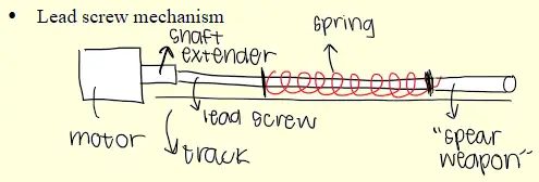
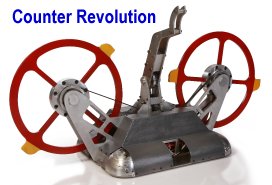
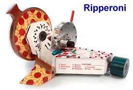
 The reason I'm asking this is because in many internet builder circles (Reddit, Discord) these days I'm seeing an upsurge in the sentiment that head on vert on vert contact is somehow partially decided by RPM (???) and not entirely by tip speed which does not really make much sense to me. This is generally supported by an anecdote and/or Youtube clip of a vertical with a measured ~200 mph tip speed launching a vert with ~250-300 mph tip speed weapon on weapon. Where I believe the RPM assumption originated is the fact that these videos tend to feature a low profile drum (inherently higher RPM to reach X tip speed) against a high profile large diameter vert (inherently lower RPM to reach X tip speed). What I think happened here is that the vector decomposition at contact resolved in the "lower tip speed" vert having a higher vertical speed at contact. Then the condition arose that RPM was somehow a determinant of engagement. Any thoughts? [Arlington, Virginia]
 The whole "Tip Speed Rules" argument says that the impactor of the slower weapon cannot 'catch up' to the impactor of the faster weapon and will therefore inevitably be struck from behind and launched by the faster weapon. This assumes that neither weapon has enough 'bite' to get past the opponent's impactor and hit some 'meat'.

 A: Mark J. I'm not a big fan of this approach to weapon belt drive.

 However: If you're going to toss four 60-pound robots into an arena with a 250-pound robot, you'd best build those lightweights with thicker armor than they would need when facing robots of their own weight. I figure the added armor mass will just about negate the weapon weight bonus from the square-cube law.


 A change from a 1.5:1 reduction to a 2:1 reduction:

 Q: These weapon performance numbers [at right] from the Run Amok Spinner Weapon Energy Calculator are looking a bit optimistic. I used ChatGPT to calculate the internal resistance of the SunnySky 2450 Kv 2212 motor since they only have the specs up to 1400 Kv version on the site.

 Q: I have been building featherweight spinners for a couple of years now and I want to look into making a pneumatic flipper. I have experience with paintball pneumatic systems and a good machine shop. I've read the Team Da Vinci pneumatics overview and your own Pneumatics Tricks and Tips page, but I'm uncertain about the sizes of components needed to produce a good flip in this weightclass.
 Q: What is the exact formula to calculate each of these for my weapon: spin up time, RPM, and KE? I know you guys have a calculator but I want to calculate by hand. [Chicago, Illinois]


 Q: What should be the max and minimum rpm of weapon
  Q: Spinning weapons are always rated by how much kinetic energy they store (joules), but doesn't momentum also matter? If you have two spinners with the same kinetic energy storage how does momentum effect their destructive potential?
  Q: Are there any advantages for front hinged flippers? It seems to me they push their opponents around more than anything else.
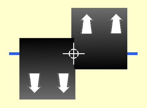 A: Mark J. Not at all practical, Icey. Although the offset drum is "statically" balanced, the drum is not even close to being "dynamically" balanced. It would shake the 'bot violently -- see: The Difference between Static and Dynamic Unbalance (video). I've added arrows depicting centrifugal forces and a symbol showing center of mass. Repositioning the mass as shown below would solve the problem.
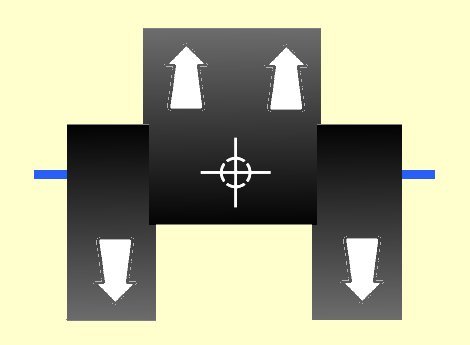
 Q: I have a cordless impact driver that claims to have over 800 foot-pounds of torque. How does it generate that much torque? Why doesn't it twist my arm off? Could I use it to drive an effective crushing weapon?
  A: Mark J. I believe you're looking for details of the "snatch weapon" developed by 'King of Bots' competitor 'Greedy Snake'. The mechanism is very clever and uses a single motor to both clamp and lift.
 Q: Magnets: specifically, electromagnets
 Q: My team just competed at NHRL over the weekend and we have a question about the results of our hits. In the attached clip we hit 'Beast' twice with the big beater bar on 'ARES' only to spin them backwards. What's the most probable reason for ARES recoiling backwards instead of launching Beast? Could this be a result of rake angle (0 degrees), too much bite, or something else? [Cambridge, Massachusetts]

 Q: With regard to the cosine correction: Yes, the correction is there for the starting condition, but it needs to be integrated across the whole hammer swing, since the newtons of downforce (adjusting the effective torque of the system) "swing" from resisting the hammer at 0 degrees, to not resisting the hammer at all (90 degrees) to aiding the hammer swing (180 degrees). The correction in the spreadsheet applies to the starting condition. ~Joseph D.
 Q: It is my understanding that wedges "counter" horizontal spinners, by deflecting them with relative ease. I was wondering if having an angle on the blade would solve this issue. For example, if there was a 'bot with a 45 degree wedge, could I make my impactor angled to match their angle to "counteract" the deflection?
  A: Note my comment above as to robot combat being chaotic.
 Q9: Which angle is best for a wedge to quickly get under opponents? [Lagos, Nigeria]
 A: Mark J. Hey since you didn't look very hard, I guess I won't work very hard on an answer. Go read the Ask Aaron Spinner FAQ. It has sections on:
 Q: Could you attach a sliding weight to a hammers arm so that when the hammer was fired it would go faster in the beginning of its arc then, due to the centripetal force, the weight would slide to the end giving it power?
  [Greensburg, Pennsylvania]
 Q: I'm building a 15 pound robot with a 4 pound bar spinner weapon for a school competition. I had selected an 1100 watt weapon motor, but someone told me that I should have 400 watts of motor power per pound of weapon to get a good spin-up time. Is that a standard ratio of motor power to weapon weight? Do I really need a 1600 watt weapon motor?
  You can simply clamp the aligned blade and pulley assembly, drill holes thru pulley and blade on either side of the shaft hole, and bolt them together. Use hardened bolts to reduce the failure rate. The diagram shows this type of attachment for a non-moving 'dead shaft' hub, but it is also suited to a 'live shaft'.
 Q: could you use a slip gear powering a winch for a spring flipper?
 Bonus Tip Don't put impactor screws in all eight of the beater bar holes. Put screws in the two 'outside' holes on one side and in the two 'inside' holes on the other side. Assembled like this the area swept by each screw head is NOT swept again on that rotation. This is now classed as a 'single impactor' weapon, which has twice as much 'bite' as a two impactor weapon. See photo above.
 Expense - Combat robots use commercial/hobby motors for economy. Really large diameter motors of the type you suggest are not available off-the-shelf; they would be custom made. Custom designs manufactured in small numbers are VERY expensive.
 Q: My motor is a flashhobby D2826. My ESC is a Xiuganpo 40 amp. I am using the Dabble app with pre-prepared code.
 Q: how does blip's [from Seems Reasonable Robotics] weapon work? [Vestal, New York]
 Q: I'm trying to get the most out of a FingerTech beater bar setup, but I'm struggling with battery life.
 I'm not following your contention that a 'Choo-Choo' linkage has a reach equal to the radius of the driven disk. I make the reach equal to the diameter of the disk plus the length of the "fling" arm attached to said disk (the dark blue arm in the animation). In the animated example the reach is almost three diameters, and the design could be modified to make it more.
 The middle layer would use a roller coaster style wheel assembly - a chain drive from a powerful magmotor would drive the middle wheel while two sections of wheels on the top and bottom layers would hold it in place. See photo. There would be 4 motors/wheels - 1 in each cardinal direction.
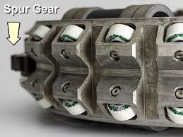


 A: Mark J. When attempting to reproduce someone's calculations you should always start with the lowest order inputs -- in this case the dimensions of the steel bar. Your calculations are correct, but you have used as an input my mass calculation output which was reported after rounding to a correct number of significant digits.
 Q: Hi. Love your site! I've been following the Golden Dukes and built a wedge and then a flipper before my spinner, and am having a blast so far. My spinner is a 150g version of everyone's favourite 'Huge' which has taken serious work, but is nearly there.
 Follow-Up: Hello again. Thanks for the explanation and reminder that robots are Newtonian objects, not magic!

 To your questions:
 Shortening Rear Bar [Crank] to 12 mm will prevent the initial 'dip' and allow the spreadsheet to run correctly, but the performance of the system is not very good: there is a very limited range of servo motion combined with a high torque requirement.
 2) The recommended lengths for Front Bar [Rocker]: D are critical for getting best lift height from lifters powering the Rear Bar [Crank] over a full range of motion. Lifters powered by the Front Bar [Rocker] may ignore the recommended Rocker length range, but should note that Rocker motion may be limited by very short Rear Bar [Crank] lengths.
 One last note: You're currently entering measurement values in grams and millimeters so the units for torque are expressed in g-mm. If you enter the lengths as centimeters the torque output will be in the standard g-cm. Yes it's easy to convert, but I suggest staying in standard units to avoid confusion.
 The image I provided is a mockup of what I'm working on, designed with a 3/8in OD shaft… yes, this is for a full body eggbeater/drum [See this archived post for an example]. It's something I've wanted to build for a long time not out of the desire to win, but because I've always loved the idea. To compensate for this more showboat-y design I have a few competitive designs in the works that'll hopefully be up and running for an MRCA event next year!
  Click the formula pic for a video description. Attempting to figure all this out for the unpredictable loading a combat robot weapon encounters is futile. I like the look of your 3/8" hollow stub axle - it passes the eyeball test. Give it a try.
 Q: Hello,
 Q: I know increasing weapon speed also increases risk of that weapon breaking under its own power on impacts. But does that also increase risk of breaking on off-axis hits from an opponent?
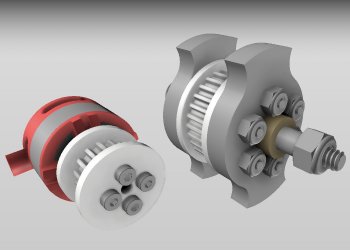 Hello, Mark! I've been working on and off with my ant as of late and have two design-related questions: [Naperville, Illinois]
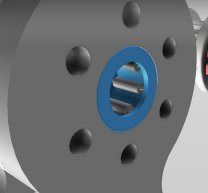 Q2: How would I go about fitting the bearings into the weapon? I don't have access to any fancy or expensive tools and figured it wouldn't be very easy to just press-fit two metal parts together.
 Q: I have a secondary 'minibot' that uses a little 16-gram disposable CO2 cartridge to inflate an for a pneumatic weapon. I'll be entering a competition that does not allow CO2 - only compressed nitrogen. I've made a refillable system using a purged CO2 cartridge as a tank for the nitrogen at 600 psi.
 Q: I bought several weapons from another builder and have been looking into putting them to good use. I have two current weapon designs, both using an EMAX 2205 2300kv motor: a hubmotor system with a 3D printed adapter (white in the render below) and a belt-driven system, more aligned with what the original robots ('Jack Move' and 'Jack Rabbit') used. I plan on replacing the locknut with what's called a “nut with conical washer” which is 12mm wide and wouldn't slip through the 9.78mm hole in the weapon. I've seen similar ideas done so many times to varying degrees of success, hence why I imitated it here… and because a few friends suggested the idea for its simplicity and ease of assembly/use. My question is this: would it be worth the weight savings and simplicity to run the weapon like this, and if so, are there any methods I should use when designing this to better improve the longevity and durability of this system?
 A conical washer nut is tempting for the reasons you mention, but if does start to loosen it has progressively less locking force to prevent further loosening. Add a drop of threadlocking fluid (Loctite) for extra security. If you need to service the weapon during an event a fresh drop of threadlocker won't have time to properly set, so keep some of the nyloc nuts as supplied with the motor handy in your spares, along with some conventional 12mm washers. Don't use threadlocker with nyloc nuts -- Loctite destroys the nylon.
 Q: I'm running a 2212 980kv brushless weapon motor with a 35 amp ESC on a 4S lipo battery in my beetle spinner. Performance is good, but I burn out one or sometimes two motors at each tournament I've entered. Should I be using a lower amperage ESC to prevent motor failures? [Ventura, California]
 Q: What's a good method to calculate the impact loads on a spinning weapon? My initial approach was to calculate force at the blade tip from angular deceleration, but I can't find anywhere that gives such information. Do you know what the ballpark deceleration force a drum spinner is subject to, or an alternate method for calculating the loads? Thanks!

 A: Mark J. The current material of choice for weapon discs is through-hardened Abrasion-Resistant Steel like AR400, AR450, or AR500. This AR steel comes in pre-hardened plates that cannot be machined by traditional methods. The discs are cut from a thick sheet by a jet of ultra-high pressure water -- a process that effectively limits the thickness of a single-piece disc. This style of manufacturing has the additional benefit of being
  Q: If two vertical spinners, one being a bar and the other a drum were to collide weapon to weapon, which design would win out? Does weapon speed play a role here?
  Q: Hi, ive been watching a lot of the TV show "BattleBots", and wanted to make my own bot. Im not gonna actually make one, but I want to model it to see what it would look like, if I could stay under the 250lb weight limit, and what it would cost. (though im not going to pay attention to the cost, or the actual science of the bot.)
 The comment was in reference to the friction drive used for the weapon, not the counter-rotating disks. Friction drive suffers from issues caused by the Square-Cube Law that makes it impractical to transmit the power required to spin-up a high moment of intertia weapon in a big 'bot.
 Q: How to activate flipper with no sensors [Dublin. Ireland]
 One advantage that Meltys have is their mechanical simplicity. There is no separate spinner shell support, no weapon motor, no gearboxes -- just one or two direct-drive motors and the exotic electronics. That's worth something!
 Q: A joule of kinetic energy is equal to a watt-second of electrical output, so if I have a spinner weapon that stores 1200 joules of energy and I power it with a 400 watt brushless outrunner motor it should take
 Unless you're prepared to design, manufacture, test, and certify your own components -- like Team Whyachi does for heavyweight 'Hydra' -- you are unlikely to piece together an effective hydraulic weapon system.
 Hello Mark, I come back once again to, our pneumatic robot is in the test phase but we have a problem with the pressure;
 Q: Hi there. Kelpie's builder David Small here. Your comments in the "Unregulated Poppet Valves with Leaky Rams" section in Tips and Tricks for Robot Pneumatic Weapon Systems are a little misguided. Kelpie's ram was hydrotested to 150% operating pressure just in case something happens and it needs to handle the full pressure. It's 100% safe and legal at any tournament. It will absolutely not "turn into a grenade". It's not just an insect thing either, this "awful" design is used in robots like Rocket the lightweight too just at a larger scale. I'd appreciate it if you update your article accordingly. [Phoenix, Arizona]
 Q: According to the Kinetic Energy calculator, my beetleweight weapon is spinning [up to]
1000 joules by 2 seconds. The Spinning Weapon FAQ said that a weapon should have the weight class of the bot in kilos x 60 x 2. That adds up to about only 163 joules. The motor in the calcs is the Sunny Sky Outrunner in the Vector Kit and the weapon is a 10 x 2 inch steel bar with a thickness of about 1/10 of an inch. Does my weapon really have that KE? [Potomac Mills, Virginia]
Q: According to the Kinetic Energy calculator, my beetleweight weapon is spinning [up to]
1000 joules by 2 seconds. The Spinning Weapon FAQ said that a weapon should have the weight class of the bot in kilos x 60 x 2. That adds up to about only 163 joules. The motor in the calcs is the Sunny Sky Outrunner in the Vector Kit and the weapon is a 10 x 2 inch steel bar with a thickness of about 1/10 of an inch. Does my weapon really have that KE? [Potomac Mills, Virginia]
 The performance numbers are likely a bit optimistic. Trying to spin a big bar that fast will generate enough aerodynamic drag to limit top speed and lengthen spin-up time. I'd guess that you meet the 'typical' spin-up speed and energy storage formula, and not much more.
 Seth did the hard work of chasing down the problem with an extensive testing program and created a new 'axe head' weapon design that eliminated the polhode problem. A word to the wise was sufficient.
 Q: Hi. Ive been enjoying reading your site for a few years and finally decided to ask a question. Hopefully this doesn't qualify as a bad hamburger or cheerleader question.
 A: Mark J. I'm glad that you are enjoying Ask Aaron! You have a choice of three types of R/C interfaces to control your pneumatic valve:
 A: Mark J. The Burkert 5404 is the solenoid valve of choice for pneumatic flipper systems because of its ability to flow a large volume of gas very quickly, but I don't think it's suited to your use. As I recall, you are building a 20 KG robot. A single Burkert 5404 weighs more than a kilo and you'll need at least two valves of this type (or one valve and a bleed hole) for your flipper.
 Q: Hello Mark
 A: Mark J. Ineffective reciprocating 'spears' have been surprisingly popular at UK Robot Wars. A few that I remember:
 Comment: Well I'm kind of sad to learn there wont be a sonic siren even if I can hit 767mph. I appreciate you bringing these up as they are important considerations. While it sounds like hitting a super sonic siren is out of the question the engineering challenge of designing a supersonic spinner is still very tantalizing. I'll look into using the most aerodynamically efficient blade I can and see if I can hook up 2 massive brushless motors plus a kick starting disengagable brushed to the weapon to overcome the massive cubed losses. Can't wait to find out what kind of physics gyro BS happens at massively high speeds. Time to talk to some overhead builders :P . Thanks for the advice guys!
 A: Mark J. I believe you're severely underestimating the energy level of an effective combat spinner weapon, Joe. The impacts are so violent that a solid steel bar undergoes elastic deformation of the type and magnitude you propose for a rubber bar, and a rubber bar would flex so much as to qualify as a type of 'flail'. Click here to find an earlier discussion on flail weapons. Go read that and come back. I'll wait...

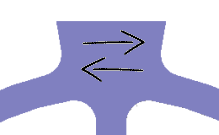
 Q: I could not find any mentions of a weapon type my team is considering using in the 15 lb weight class. Our design is utilizing a spinning shell around a stationary core, with 3 portions of chain from a chainsaw with weights on the end. The chains are going to be short enough to not be considered an entrapment device.
 Q: My question this time involves flails. Simply put, what chain length to flail weight ratio is the best? Also, why has nobody ever mounted flails vertically, like on a drum or a flywheel? Finally, would a horizontal or vertical mounted set of flails do best? [Urbana, Illinois]
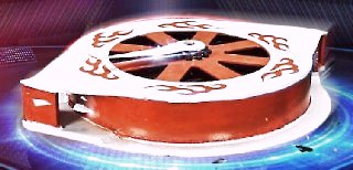 Q: So here's a question: there was a Chinese competitor called... Flame Wheel? Hot Wheel? Not for sure, it's one of those two names. Anyways, I was wondering if there's any advantage to having the [impactor] mass placed outwards like seen in this picture in comparison to having small, sharp teeth like Gigabyte or Captain Shrederator.
  A: Mark J. The robot is King of Bots season 2 competitor 'Fēng huǒ lún' or 'Flaming Wheel'. An unrelated robot fought in King of Bots season 1 under the name 'Hot Wheel'.
 Q: Hey there, Mark! This might be a dumb question, but I'll ask it anyways. Over on Facebook people mentioned the Fingertech vertical spinner which is apparently [expletive deleted]. I noticed, however, that somebody mentioned if it was crafted from AR400 instead of Titanium, it would hit harder. Why? Is it because of the mass increase? Is that really enough to make this spinning weapon more effective? [Kankakee, Illinois]
 There are a few insect-class flippers using exotic electric servos, but the square-cube law pretty much rules out heavier flippers directly driven from an electric motor. Sub-lightweight electric-kinetic flippers store up energy in a flywheel to get enough 'pop' to launch opponents. The only remotely successful heavy electric flipper has been Team Whyachi's 'Warrior SKF' (aka 'Warrior Clan' and 'Warrior Dragon'), although many of their victories have been via direct attacks with their flywheel/spinning disk rather than attacks from their anemic kinetic energy flipper. Here are the primary problems:
 Q: My 1lb antweight is exhibiting some odd behavior. The weapon blade is the fingertech titanium blade. I have a V-spec 2205 motor, a 450mah 4s 70c battery, a 20a brushless ESC and two fingertech ESCs with accompanying silversparks. When I spin my weapon up to max or near max throttle one or more of these behaviors *sometimes* exhibit themselves: The power LED starts flickering, the robot starts doing donuts, power to the weapon motor gets cut and it spins down. As soon as I turn the throttle down it fixes itself and its free to spin back up again. Is this a problem with the weapon ESC not being able to handle the weapon? [St. Louis, Missouri]
 A: Mark J. You're correct, Jack -- but I'm not sure where you're going with this.
 For a spinning bar weapon 450mm by 75mm by 24mm in the usual spinner orientation:
") Improved 'bite' allows you to design a lighter bar and spin it at higher speed to attain the same energy storage as a heavier bar without sacrificing the ability to deliver a solid 'hit' on your opponent. If your design features a long bar that needs to be thick and heavy for structural strength and it spins slowly enough for good 'byte' (think 'Tombstone') there is little advantage to going asymmetric.
Improved 'bite' allows you to design a lighter bar and spin it at higher speed to attain the same energy storage as a heavier bar without sacrificing the ability to deliver a solid 'hit' on your opponent. If your design features a long bar that needs to be thick and heavy for structural strength and it spins slowly enough for good 'byte' (think 'Tombstone') there is little advantage to going asymmetric.
 An alternative twin-spinner system design is employed by 2018 BattleBots competitor 'Double Dutch'. Their design features counter-rotating bar spinners placed above and below the robot body. Although both weapon bars can attack an opponent at the same time, it's likely that one bar with strike before the other and throw the opponent clear before the second bar can impact. Almost certainly the two potential weapon impacts will strike different locations on the opponent, which will also limit their effectiveness.


 Q: Hi Mark, I had a follow up question about the spinner spreadsheet. Your explanation was very helpful and brought much comfort. I know the 7lb bar is overkill but I wanted to try something like that at least once just to see what would happen in the area upon contact. Overkill is underrated. Maybe...


 2) My second question concerns a snail cam design for a spring flipper. I'm aware that you've been asked questions concerning this topic multiple times and have read through all relevant posts, but for my design I've attempted to adjust the parabolic spiral to allow for a continuous length for the final 1/4 of the rotation to allow for leeway when winding and to prevent misfiring. The motor still seems to struggle to wind spring loads it should be perfectly capable of, and while there may be other issues in the design that could cause that, I believe the cam contributes to the problem.

 Comparing the old cam design to the new one, I noticed that where the difference between the two was at its greatest was where the gears in my motor sheared, so your theories on load seem bang on! The fact that it's not a direct pull down is still an issue, but that would require more adjustments to equations, and the old mechanism was able to wind that part fine with a similar profile, so I should be alright there. I'll also keep your tips for HDPE in mind when working on the new cam.


 Q: I just got my first disk weapon back from the metal shop and I think it has some problems. Builders are telling me that the sharp internal angles on the spokes are places that will start fractures. Worse, the water jet cutter overshot and left some little notches in the corners. I think I'm in trouble.

 I'm putting together an antweight with a somewhat experimental weapon. The weapon would be a slightly different take on the overhead saw. Instead of a single abrasive disk trying to cut its way inside the opponent, it would be 4 or 5 abrasive disks put together to create a single thick disk. The idea would be that the thick abrasive disk wouldn't necessarily cut through, but rather take large scoops out of the opponents top armor. Admittedly, it wouldn't be the most efficient way to get to the insides, but in theory it would cause quite a bit of visible damage on the opponents' topside and hopefully create a terrific spark show...if done right.
 Q: When designing a heavyweight [electric] hammer (potentially applies to other weight classes) I've seen builders use a slip clutch at both the motor output or at end of the reduction the hammer shaft/sprocket connection. Is this just preference or is there a practical advantage to one vs the other? [Seattle, Washington]
 A: Mark J. Viable? The most feared and successful combat robots to ever swing a hammer/axe have been pneumatic rack and pinion designs.
 Q: Would a fingertech chipper blade work on a direct drive overhead 1lb spinner, or would a blade that has a "bow tie" design (think bow ties made of AR400) similar to Cobalt's large impactor, except there's one on each side work? I think it will work better due to the outward weight distribution.
 I should warn you that a long direct-drive spinner design is very hard on the motor. An unmodified outrunner really isn't designed to absorb the large side-loading it will take from weapon impacts. Pack a few spare weapon motors if you go that route.

 Q: Hi! I was wondering if there were any advantages of 'Kraken' having a Pneumatic Crusher over a hydraulic or battery powered one. Ty and Robots ftw! [Providence, Rhode Island]
 Q: Hello! I just had a quick question about lifting mechanisms. I've noticed that some lifting mechanisms, like the ones on the featherweights Banana Bender (AUS) and Mad Rush (UK), as well as a number of lifting mechanisms on UK ants that use an angled piece that connects to the lifting arm rather than having the motor connected to the weapon itself.
 Q: Hello, Mark! I was thinking about the question I had a while back about how people turned mixing bowls into full-body spinners, and remembered that both Ziggo and Blendo were made from wok pots (IIRC). As with that question, I am simply wondering: how on earth do you turn a wok pot into a spinning shell of amassed destruction? I'd assume their cast-iron structures would gave them more problems than it'd be worth. [Jacksonville, Illinois]
 Q: Hi Mark.
 A: Mark J. You appear to have mistaken 'Ask Aaron' for 'Instagram'. Should you submit another question here, please do take a moment to read the explanatory 'thank you for your question' page that appears after your question is submitted.

 Q: OK, Mark! RESET I have a question regarding a featherweight lifter.
 Q: Hey Mark. Let's talk theory.
 A: Mark J. Don't confuse 'power' and 'torque', Champaign. Mechanical power is expressed as rotational force (torque) multiplied by its rotational speed (RPM). A reduction gearbox will increase output torque and decrease speed in equal measure -- there is no increase in 'power' regardless of the gear ratio.
 Q: Hi Mark, Had a conceptual question about impactors on horizontal spinners. Traditionally, the inserts come to a triangle point with the hypotenuse facing bot. Is there any sense in making a vertical ramp impactor to get under opponents instead of a straight line to hit anywhere in the height of the weapon?
 Everyone is hype about single tooth blades for "bite" but why? What does bite actually do for you? It is heavier engagement on a piece of material which is arguably more energy dissipated just because it has nowhere to go.
 A: Mark J. Thanks for the 'Run Amok' shout-out, Massachusetts.
 A different double-spinner approach is seen in antweight 'Not So Free Hugs' which has twin saw blades on articulated arms. The idea here is not impact damage but the ability to trap and saw into soft wheels or plastic side armor. Here the ability to access different locations on the opponent is a benefit as it gives a greater chance to find something vulnerable to saw damage.
 Q: Hi Mark, I'm working on a hobbyweight horizontal spinner and wanted your opinion. There are spinners like 'Last Rites'/'Tombstone' that ping pong like a fbs after impact and others like 'Hazard' that barely turn. I looked in the forum and read up on Hazard's faux clutch and don't fully understand it. So really 3 questions:
 Q: Hi Mark, it's drum spinner guy again. Here is my weapon design thus far. The length is fixed, the radius is flexible, but the larger the better obviously for energy storage. I fell it's overbuilt just because of its weight, but wanted your take. This is for a 15# robot.
 Q: How can you design a single impactor or snail style drum weapon and assure it is balanced? Every time I start to design one in Autodesk Inventor, I keep making it an egg beater or really asymmetrical, and doubt its balance. [Pittsburgh, Pennsylvania]

 Q: Hi, single tooth drum guy again. What screws are recommended for attaching an impactor to a drum? It is bad design practice as the force on the screws is sheer force, but I do not see another way around it. Just looking at alternatives to a unidrum as it gets very complicated very quick.
 Q: So I heard that 'Warrior Clan' or now called 'Warrior Dragon' used kinetic energy from their spinner. Is this true? If so how? By the way I'm a big fan of your website!
  Q: Hey, Mark! Apologies for sending you a question right after my last bunch, but it wasn't until this morning that I actually remembered it. Okay, so I noticed 'Wrecks' uses a vertical flywheel that is much thinner than conventional flywheels.
 That blade allegedly can't cut plywood! I think the motor choice is good, and i'm going indirect drive.
 A motor and saw blade on the end of a simple arm directly attached to a servo forms a lever that greatly multiplies force placed on the blade end and focuses that force on your servo. The servo isn't going to be able to exert enough force to apply cutting pressure on the blade, and the blade is going to kick back enough force to destroy the servo. At very least your saw arm should be strongly hinge-mounted to your chassis, and your servo should attach to the arm via a link and servo-saver to isolate it from side forces -- a simple 4-bar linkage.
 Since you made no reference to a belt drive system I assume you're planning direct-drive from the motor to the saw blade hub. You'll want to keep as much of the load created by the saw on the more strongly supported bearing nearest the motor mounting. Do not hang the whole assembly off the end of the motor farthest from the mount!
 Q: Hey, it's me again! I found the video where I saw Legion's Flipper! You can see it at 1:58 when it lowers and you can see it again better at 2:04.
 I've noticed that there are usually two kinds of full-body spinners: those that are low and flat, like Capt Shrederator, and those that are big and square-ish, like Megabyte and Gigabyte. What pros and cons come with each of those designs or, more specifically, those shapes?
 A: Mark J. I've heard that same theory. It's based on the statistical likelihood that the weapon with the higher RPM (but lower tip speed) may land the first impactor. While true, that impactor will land on a surface that is moving upward faster than it is, so the smaller weapon has no opportunity to dig in and 'throw' the larger weapon. The best that can be hoped for from such an impact is that the larger weapon may be 'bumped' up and back by the glancing blow to a curved surface with little bite.
 Newton's third law of motion states that for every action, there is an equal and opposite reaction. This means that when your kinetic energy weapon strikes your opponent the impact on your weapon and its support structure is as great as the impact on your opponent. There isn't any escaping this 'kickback' force: your weapon has to be strong enough to withstand this impact. The advantage you have is that you know the place and direction of this force, while your opponent may have to take this force pretty much anywhere.
 Q: Looking at the previous questions and answers, what are your thoughts on bots like Brutality in the modern era Mark? Recently just watched a match of it with Last Rites back in the late 2000s, the wedge seemed to have made it under Ray quite easily. [San Jose, California]
 A: Mark J. Have you noticed that Team Whyachi isn't using their own gearboxes to power their weapons? Take a look at this recent post about the 2016 version of 'Son of Whyachi'. Their weapon drive solution meets your design goals with much less weight, complexity, and expense. Team Whyachi has been running a common spur gear weapon drive across multiple design revisions with good results.
 Q: Hey, Mark! Just had a quick question: I noticed a lot of eggbeaters don't have leading wedges and instead use flat fronts, such as 'Bigly' and 'Conker 3'. Is there an advantage to having a flat front on an eggbeater? Are there any drawbacks? [Champaign, Illinois]
 The first step is to model the performance of the weapon system to find out how quickly the start-up current surge lasts. The A28-150 AmpFlow has a stated armature resistance of 64 mΩ, which would give a stall current of 375 amps -- but there is additional resistance in the battery/wiring/ESC. Adding in 20 mΩ (my default 'guess' factor) for those other circuit elements brings the real-world 'stall' current for the A28-150 to about 285 amps @ 24 volts.

 Q: Heres a cad of the idea. The spike is the spike that spins. Is there anything you would add to make it better? Thanks! :)
 Q: Does the shape of the bar on a bar spinner make any difference? Thanks! :) [Lynn, Massachusetts]


 There have been many attempts at robots with multiple/interchangeable weapons, and very few have done well. You may be interested in reading up on 'Bombshell' -- a heavyweight robot designed around a modular interchangeable weapon set. 'Bombshell' was constructed by a large, well-financed, very experienced team -- this is not an undertaking for an inexperienced builder.
 Q: How does 'Bronco' make his pneumatic flipper so powerful? I heard pneumatics are normally slow and not that powerful. Thanks! :D (M) [Lynn, Massachusetts]
 Q: I intend to build an underweight beetleweight lifter. The mechanism at the moment is a 4 bar lifter powered by a servomotor. Judging by the T.I. tool, it appears that the front bar 'H' should be driven in a frontbar setup. Is it alright if I attach my servo to the rear bar 'F' though?
[Paris, France]
Q: I intend to build an underweight beetleweight lifter. The mechanism at the moment is a 4 bar lifter powered by a servomotor. Judging by the T.I. tool, it appears that the front bar 'H' should be driven in a frontbar setup. Is it alright if I attach my servo to the rear bar 'F' though?
[Paris, France]
 I'm presently powering it with an E-flite Park 250 motor:


 Q: What is the purpose of 'True Grit'? Its weapon seems dumb. [Williamsport, Pennsylvania]
 Does the motor actually pull that many amps? No, because:
 Would it be reasonable to attempt to mount a sprocket to a brushless motor in a similar style to the riobotz DIY friction clutch (p.142 of riobotz manual) using a stock mounting fixture (pic at right)? I'm not sure how else to go about it before biting the bullet and getting something machined for purpose.
 I'm a believer in Trantorque keyless hubs for functional and robust off-the-shelf hub solutions. They expand their outer diameter and decrease their inner diameter when tightened to create in interference fit to the shaft and sprocket/pulley bore simultaneously. This is much more secure than clamping the sprocket between compressing plates in the manner of a prop mount.
 A: My suggestion about an 'off-axis hole and pin' was a poor-man's keyway and key substitute. I'm unable to guess at the shaft diameter of your prop mount, and a small shaft made of soft material (aluminum) isn't a good candidate for a keyway. A steel pin pressed deeply into the aluminum base has a better chance of surviving without weakening the shaft -- see sketch.
 Q: Hello! It's me again! I had a question after watching 'King Of Bots'. So, I'm sure you're aware of the Russian entry 'Stingray'. Well, I was wondering what you think about the design for the drum?
 Q: Is the Saifu kit a drum or an eggbeater? [Beckley, West Virginia]

 Again, can't thank you enough for all the help you've provided. This is my go-to resource for bot building information and you've compiled an amazing collection of tools and advice over the years.
 Q: What exact purpose (other than serving as a directional tool) does the arm of Megabyte serve? [Decatur, Illinois -- close to Champaign]
 A: Mark J. You've been caught in a dimension input difference between the calculators, Rob.
 Q: Hi, I have seen somewhere that a robot used a banebot wheel for a spinning disk. What are the advantages and disadvantages of using a wheel for a spinner? [Great Falls, Montana]
 A: Mark J. I'm told that there aren't many combat robot builders in Germany and that the German Roboteers Association doesn't know of anyone building a drum robot such as you describe. They'd like to get in touch with you.
 2. I am competing in the BotsIQ team for our high school and we would like to design a 'Ciclone-esque' bot but are having difficulty with one rule in particular:
 Q: Hi mark an old builder from [someplace]... I was off the work from some time... leave it... I was thinking about to build a wedge bot (actually tired of drum and disc in [someplace]... yah here are too much of them)...
 Q: What would be the most appropriate motor for my robot idea to use? Yes, a flipper and axe (or more rather a hammer, or a plank of wood with a nail in it) as one weapon don't go together, but I want to have one single 180 degree weapon.
 2k RPM
 A: Mark J. Two design elements that don't work -- let's put them together! Yes, the reduction calculation is similar to a V-belt system:
 A: Mark J. I can post formulas and diagrams about gyroscopic forces that go on for pages, and in fact I have: search the Ask Aaron 'Robot Design' and 'Robot Weapons' archives for 'gyroscopic'. If you really want to understand gyro forces I strongly recommend that you purchase a small toy gyroscope and play around with it.
 Q: The is the three options for horizontal spinner guy. I was doing some research with the Rio Botz tutorial on the issue and came across this picture. Looks like you are right about not trusting the Team Whyachi shaft. I'm going with a 1.75" Ti 6AL4V ELI shaft (including bearings and external shaft to hold the sleeve bearings 2.375") and a chain drive (ala Tombstone).
 A: Mark J. There is a good discussion of the benefits and drawbacks to threadlocker vs. nylon inserts at eng-tips.com. Briefly, threadlocker holds better than nylon IF properly applied to clean threads and allowed to fully set, while nylon inserts are foolproof and immediately useable. If there is a chance that I'll need to remove the bolt and replace it between matches I'll use nylon, otherwise a carefully applied threadlocker is my choice. Don't use both -- most threadlocker compounds don't mix with plastics.
 A: Mark J. The RioBotz Combat Tutorial was written in Portuguese and loses a bit in translation. The descriptions are also a bit brief in places. To be fair, 'Ask Aaron' probably doesn't translate well into Portuguese.


 Q: Hello, I have 2 questions. Bot info:
 The 20:1 ratio P60 gearboxes with the 2.375" wheels give the best performance from the RS-395 motors in a moderate size arena: around 5.5 MPH, reaching that speed in about 6.5 feet. That's ample speed and power to push around a big spinner weapon. The 26:1 gearboxes would be a little easier on the motors, but the 20:1 should be fine.
 Q: And if vertical spinners supposedly generate more kinetic energy then why do people use horizontals? [Baltimore, Maryland]
 Q: I saw some of your old answers about 'Beta' and I thought I would investigate how much better 'Beta' is than just using regular gears, but I couldn't figure out if I was doing it right.
 Q: I'm planning out a hobbyweight Tombstone-esque horizontal spinner. I was recommended to use an outrunner of 1000-1500 Watts for the weapon motor, and I found one that's 70mm (2.75591'') tall when oriented appropriately. Meanwhile, I found another outrunner that's not much heavier, but has over 2000 Watt power. The problem is, it is 83mm (3.26772'') tall.

 Q: Hi Mark, what is an EDF brushless motor, and is it a good idea to use them on lighter bots to power spinning weapons? [Sydney, Australia]
 Q: Alright, I'm here with the last question for a while (to let other people ask questions) - I've been really interested in HUGE drum spinners. However, I'm needing to look for some inspiration for a design. I currently have a few "big drum spinner" designs in mind, like REDRUM, Fluffy 2, and Barber-Ous. However, I'm looking for some other large drum spinner designs as well. Note when I mean huge, I mean freakishly huge (larger than Yeti's). Also, I do know the pros and cons with drums that are much, much bigger than normal (I did do a bit of research already on that). Any names you can think of to look up and research in terms of HUGE drum spinners?


 Q: Hi, my team is planning to build a [heavyweight] vertical spinner as shown in the image. The diameter is about 16 inches, and the total mass is about 43.358 Lbs. The bite is 2 inches. What would be the optimal RPM? [Buzzards Bay, Massachusetts]
 Q: I am looking at building a 30 pound robot this year, and had a question for the lifter which will be around a foot long.


 Q: After some thought I think I want to make an undercutter type spinner either 12 or 30 pounds. I came up with the attached sketch, nothing is to scale, which is my question.


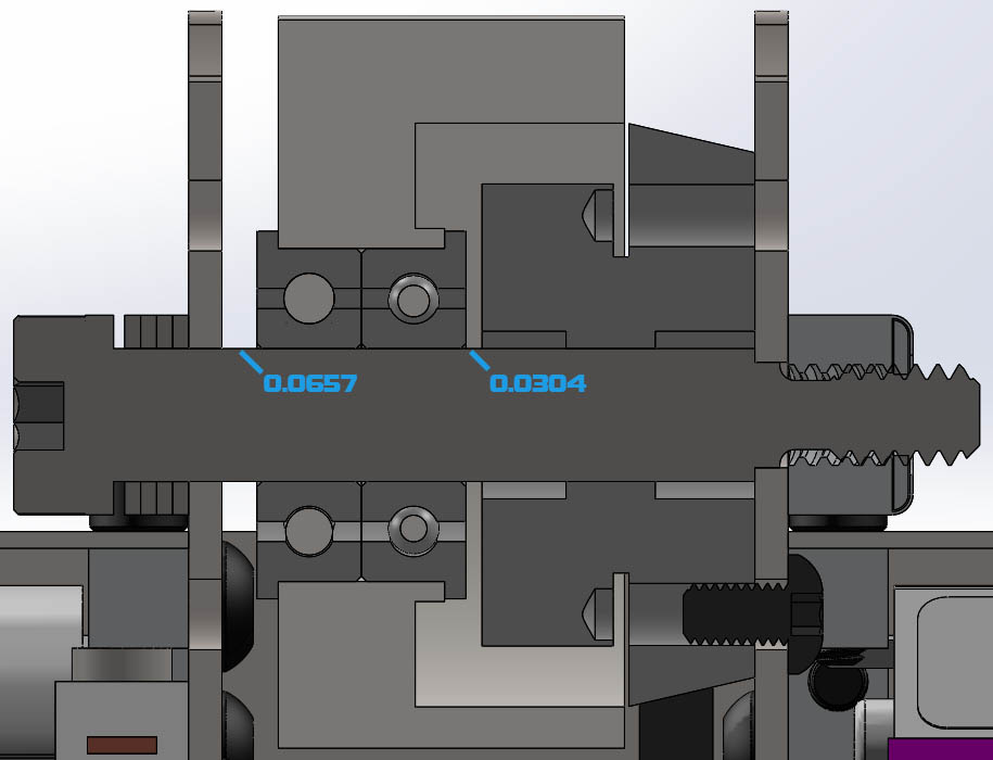