|
|

Questions and Answers about Combat Robotics
from Team Run Amok
Privacy Policy

This page is one of several archives of 'Ask Aaron' questions and answers categorized by topic. To see the most recent questions or to ask a new question, go to the Ask Aaron Home Page.
Take a tour of posts in this Ask Aaron Archive that have been referenced to answer new questions. Click the 'Mystery Post Tour' button above to get started.
|
Aaron's Wisdom I've said this often but builders don't want to believe me:
The weapon may be the least important system on a combat robot.
If you're not winning matches it isn't because you have a poor weapon.
|
Drivetrain, radio set-up, general construction practice, and weapon/chassis balance are all much more important than the type of weapon you choose. There are plenty of examples of winning robots with ineffective weapons, and there are many more examples of losing robots with awesome weaponry. If you get the basics right you're going to have an above average robot no matter what weapon it carries.
|
Date marker: January 2017
 Q: Why does RioBotz choose to have 13 radii and 18 sections [in the design of their integrated single-tooth 'snail drum' weapon]? [Dublin, Ohio]
A: Mark J. The selection of 18 initial sections was arbitrary -- it came from dividing the 360 degree polar coordinate plot into twenty-degree sections. That seemed to be a reasonable number of facets to machine into the drum in the final design. Two of the sections (40 degrees) were combined for the impact tooth at full radius and one section is the curved 'tooth notch' designed to reduce stress concentration that has no single radius. Then:
|
"After observing the nearly flat shape of the optimal solution in the regions between 220o and 320o... the algorithm [was] re-evaluated considering only 2 flat sides in such region. This new optimal solution is very similar to the previous one, but it is easier to machine due to the reduced number of facets." -- Drum Shape Design and Optimization Using Genetic Algorithms
|
The creation of just two facets ('k' and 'l') in the region from 220o and 320o reduced the number of radii to thirteen.
Q: Hi Aaron, could you tell me, for a spinning drum that stores 10,000J [30 Lbs class] what is the difference between a 10mm bite and a 20mm bite? Thanks. [Valle del Cauca, Colombia]
A: Mark J. Bite (what's bite?) is calculated as a maximum depth of opponent insertion into the arc of a spinning weapon at a given weapon RPM and forward velocity. You'll get that maximum bite rarely, just like 13 black only comes around rarely on a roulette wheel. Sometimes your luck will be very poor and you'll hit your opponent just as an impactor is facing them and get no bite at all! On average, you'll get half the max bite -- less as your attack speed drops.
- Consider an opponent who was wise enough to avoid exposed sharp edges in their robot design. Given a nice sharp angle to attack you don't need a lot of bite, but if you're forced to attack a flat or gently curved surface you need all the bite you can get.
- Greater bite also is a bonus when your attack velocity drops. A weapon with a lot of bite can still be effective in close quarters when you don't have a chance to back away and take a high-speed run. Watch some combat videos and pay attention to the speed at which most weapon hits are made.
What's the difference between 10mm and 20mm bite? A few more match wins. Bite is good -- more bite is better.
I've been writing quite a bit of JavaScript lately, so what's a little more? Take a look at the new 'Bite Calculator' in the Spinner Weapon FAQ.
Q: Why doesn't 'Witch Doctor' have gyroscopic forces acting on it? One side doesn't lift. [Reston, Virginia]
A: Mark J. See this post on gyroscopic forces a little farther down in this archive.
Q: Hey Mark,
How does the flipper on Lock jaw in Battlebots Season 2 harness the power of the springs? From what I could tell it was winched back but how was it able to fire then reset again? Additionally, could this method of flipping be utilized in all other weight classes as an alternative to pneumatics? Thanks in advance! [Straight Outta Facebook]
A: Mark J. Donald H. doesn't divulge much about his robot designs, and I can't see enough detail in the photos of 'Lock-Jaw' to understand the clutch mechanism. Fortunately there are builders who do share their spring-powered flipper designs:
- Dale Hetherington has built pretty much every exotic robot design there is. Take a look at his very detailed build log for 'Dead Air'.
- I'm personally very fond of the snail-cam spring loader for it's simplicity and adaptability to small weight classes.
That will get you a start.
Q: Hello Mark,
I've heard it said that Wrecks' vertical disk (30-35 lbs) has a much higher Moment of Inertia than Electric Boogaloo's vertical spinning weapon (~70 lbs). With the assumption that Wrecks is using a similar motor (big assumption), how is this possible?
-David R. [Livermore, CA]
A: Mark J. A little clarification:
The Moment of Inertia (MOI) is NOT a direct measure of how much energy a spinning weapon stores; the motors or speed of rotation have no bearing on the moment. MOI is a measure of the energy needed to change the rate at which the weapon is spinning. Its value depends on the mass of the weapon and (most importantly) on how that mass is distributed relative to the rotational axis.
Consider:
- A small chunk of matter is rotating around an axis at a given RPM at a distance of six inches. With each rotation the chunk of matter travels a distance of ( 2 × 6" × pi = ) approximately 37.7".
- That same small chunk of matter is now rotating around an axis at the same RPM at a distance of 12 inches. With each rotation the chunk of matter travels a distance of ( 2 × 12" × pi = ) approximately 75.4".
- The chunk of matter 12" from the axis must be travelling twice as fast as it did when only 6" from the axis in order to complete a revolution in the same length of time.
- The kinetic energy of a moving object increases with the square of its velocity (K = ½mv2), the mass 12" away from the axis has four times as much kinetic energy as an equal mass 6" from the axis when rotating at the same RPM.
- Doubling the distance of the mass from the rotational axis doubled the speed of the mass, which raised the energy stored by the spinner at any given speed by a factor of four (velocity2). This also increases the MOI of the spinner by a factor of four, even though the mass of the spinner has not increased.
Now, let's take a look at the spinner weapons on 'Electric Boogaloo' and 'Wrecks':
 'Electric Boogaloo' has a bar spinner weapon - closer to 50 pounds than 70. A bar has a lot of its mass close to the rotation axis and relatively little mass far from the axis. The formula for the MOI of a rectangular bar spinner is:
(mass ÷ 12) × (length2 + width2)
'Wrecks' has a large diameter spinner with most of the mass concentrated in a ring at the outer edge -- far away from the axis of rotation. The formula for a the MOI of a thick ring (discounting the supporting spokes) is:
(mass ÷ 2) × (inner radius2 + outer radius2)
Let's use the new Run Amok JavaScript Spinner Weapon Calculator to compare the MOI of the two designs based on rough estimates of their sizes:
-
A steel bar similar to the spinner weapon used by 'Electric Boogaloo': 455 mm long by 160 mm wide by 40 mm thick weighs 22.7 kg and has an MOI of 0.440 kg·m2.
-
A steel ring similar to the spinner weapon used by 'Wrecks': 300 mm outer radius, 200 mm inner radius, and 12 mm thick weighs 14.7 kg and has an MOI of 0.956 kg·m2.
The ring weapon is less than 2/3 the mass of the bar weapon, yet has more than twice the Mass Moment of Inertia. That's a much more efficient use of weapon mass for energy storage.
Q: How do electric hammers not burn out [...just down the road from Ashburn, Virginia]
A: Mark J. If you aren't careful they do burn out.
The motor for an electrically powered hammer weapon needs to be powered off at either end of the weapon swing to avoid an extended 'stall' condition where the motor would consume damaging current levels. This can be done a couple of ways:
- Most builders control the hammer with one of the spring-centered joysticks on the transmitter and release the stick at either end of the weapon swing. Just don't forget to release the stick!
- Some R/C relay boards and a few ESCs (like the Talon SRX) have provisions for 'limit switches' to sense when the controlled device has reached the end of its travel and automatically shut off power in that direction. This allows an electric hammer to be actuated by a simple single-throw switch on the transmitter -- typically channel 5.
Q: Hello! I am a high school student that I building a new robot. I am building a drum spinner, and that spinner will be operated by a Brushless motor with the specs of:
- Turns: 10T
- Voltage: 12S Lipoly
- RPM/V: 560kv
- Motor Poles: 10
- Internal resistance: 0.017 Ohm
- Max Loading: 100A
- Max Power: 4200W
I currently do not have the dimensions of weapon itself, but I am interested in knowing the "equation" in finding the speed of the weapon at full speed. I have the Wh of the battery, Volts, and most of the other specs. Also, where can I find the equations to calculate torque, and stall torque. [Dublin, Ohio?]
A: Mark J. What's wrong with this group of questions?
Given the syntax, grammar, and language structure, I have trouble believing that the author is from Ohio. Further, the motor and weapon design are unusual for a combat robot that might be constructed by an American high school student in the mid-west.
If the author is a high school student in Ohio and they are building a combat robot this size, they should have a local mentor to guide them in design, construction, and safety. The mentor should be providing the answers to questions like these.
Either way, I'm not comfortable answering your questions. The best I'm willing to do is to point you to this Wikipedia article on 'Motor Constants' and warn you that stall torque on brushless motors is much less than the calculated value due to the software in the motor controller limiting current at low motor speed.
 Q: How to make 2 [pneumatic] cylinders work in sync? Use 2 buff tank and 2 valve or 1 buff tank with 1 valve [to] supply 2 cylinders? Thank you (just like Subzero) [Yunnan, China]
A: Mark J. I see that you've just asked the same question of Subzero's builders on their Facebook page. The better question might be, "Why use two pneumatic cylinders instead of just one of larger diameter?"
If I had to use two cylinders I'd want both to fill from a single gas supply thru a single valve to avoid any pressure imbalance. Why don't we wait a few hours and see what the builders say?
Subzero's builders did reply a few hours later:
|
Team Hammertime / Teamxd: That version was one supply tank with 2 rams, one valve and no buffer tank.
|
|
Q: What's the best & safest way for someone who's only done non-weaponed bots to do their first weaponed one? [New Jersey]
A: Mark J. I'm not sure how to respond to 'best' but I can offer some safety guidance. You didn't mention how large a robot you are interested in building or the type of active weapon you are considering, so I'll have to keep this general.
- Review your basic workshop safety practices:

- Wear eye protection when there is danger of flying chips, abrasive dust, or irritants.
- Remove rings and other jewelry before operating machinery.
- Keep your workspace and the floor around it clean and un-cluttered.
- Securely anchor materials being drilled, ground, or machined.
- Cover and secure sharp edges and points in the work area when not in use. Use gloves where appropriate.
- Do not wear loose clothing around power tools -- a work apron may be appropriate.
- Monitor your lithium battery charging, and use a suitable charging container if needed.
- If it's gonna be loud, wear hearing protection.
- Keep safety restraints on weapons that prevent them from operating unexpectedly until you are ready to test/use the weapon.
- Do not test or operate your weapon without containment suited to your weapon and robot.
- Be cautious of mechanism pinch-points: articulated levers, chains, hinged surfaces.
- Keep your design and expectations at a level appropriate for your building skills and resources.
- If you aren't sure you understand the safe operation of specialized equipment, fittings, or assemblies -- ask!
Q: Dear Aaron, which horizantal spinner has more effect on the other bot? And to you? Thx, [Google Fiber ISP]
A: Mark J. I'm not sure I understand your question. The base physics of a horizontal spinner are the same if it's a bar or disk -- or a top/mid/undercutter. The effectiveness depends on other factors such as energy storage, 'bite', and chassis stability. Suggest you read the Ask Aaron Spinner Weapon FAQ and then send in a more focused question.
Q: Is there a way to calculate a spinning weapon's gyro effect? I've seen bots that were similar to each other yet one had HUGE problems with gyro and one didn't. How can I make sure ours isn't like the first one? [Kansas City, MO]
A: Mark J. There are multiple posts about designing to minimize gyroscopic forces on your 'bot in the Ask Aaron Combat Robot Design Archive -- search there for 'gyroscopic'.
Many of those posts refer to the Total Insanity Gyroscopic Effect Calculator as a tool useful in adjusting robot design to better cope with the weapon gyro forces. The T.i. gyro calculator requires the 'Mass Moment of Inertia of Weapon' as an input, which can be calculated with the Run Amok Spinner Weapon Calculator
 Q: Hi again, I've stumbled upon a problem, the snail cam spring reloader [needs to stop] after one full rotation, I cannot seem to find a suitable solution to do so with a gear motor. Do you think a stepper motor is better for this or is there a way to make motor start and stop after one rotation and a push of one button if you will. [Bristol, UK]
 A: Mark J. When you turn off the windshield wipers on an automobile have you noticed how they continue for the rest of the wipe stroke and then stop in the park position? That's what you're looking for and here's how you do it:
- The circuit shown at right allows the gearmotor to run until the flipper arm (not shown) reaches the fully loaded position and presses down to open the 'interrupter' micro switch -- stopping the gearmotor.
- A momentary closure of the normally open R/C switch re-starts the gearmotor long enough to fire the flipper, which closes the interrupter switch.
- The gearmotor then continues to run thru the rest of the reload cycle to an automatic stop.
The positioning of the micro switch is simplified if you use a lever-style switch that can be bent to fine-tune the switch point. The micro and R/C switches must have enough current capacity to handle the gearmotor, and the micro switch must be wired 'normally closed' (NC). For larger robots the micro switch can trigger a relay with the capacity to handle the motor load.
Q: I was actually thinking to have snail cam consist of 2 shapes, 1) the main cam and 2) a smaller cam with sudden increase in radius where reloading needs to stop that way there is no need for finest tuning. [Bristol, UK]
A: You have lots of options on the interrupter. A micro switch is simple, but you can certainly use other sensor types: infrared emitter/detector, inductive proximity, magnetic... whatever you're comfortable with.
Q: I was wondering if you have heard of or made any progress on getting the T.i. 4 Bar Simulator ported to a newer version of Windows. Thank you for any information and providing a valuable service. [Kansas]
 A: Mark J. The author of the T.i Four Bar Simulator wrote the code back in 2007 when he was still in school. He tells me that he's not sure where the source code is, but that it may or may not be on an old desktop which he believes is stored in his parent's attic. The best he could offer was to take a look in the attic the next time he went home for a visit. In my mind I picture a dust-covered computer leaning up against the holy grail and partially covered by a lost da Vinci manuscript.
I keep an old Windows XP desktop next to my 'Super Nintendo' console in a dark corner of my basement just so I can run 'Four Bar' and play 'Donkey Kong Country'. A similar set-up may be your best option as well.
Q: Hi there,
I've got an idea for a spinner robot where the rotating ring spins inside a circular chassis, and once it reaches a sufficiently high speed, two 'teeth' on the ring are extended (to protrude beyond the chassis) by centrifugal force. On impact, the ring is slowed, meaning the teeth retract again (using a spring), leaving the ring to spin up again without external resistance. This would mean the ring could spin up and inflict damage on an opponent, even if the opponent was continuously in contact, since the teeth would be shielded by the chassis until the ring was at full speed.
I haven't been able to find any examples of a robot which uses this system, so my question is, are there any, and if not, why not? I feel there must be some fundamental reason why robots don't use such a technique - do you have any suggestions?
Many thanks, M [Bournville, England]
 A: Mark J. I know of no examples of such a weapon system in use, and I think I know why there are none.
Spinner weapon teeth take huge abuse. The entire force of the weapon is transferred thru them to the opponent. Typically they are made of hardened tool steel and set into well braced recesses in the weapon body where they are secured by the best quality bolts obtainable. Still, an impactor tooth's life is short. A good impact can and will shear them away.
Your proposed design places the impactors on pivots which would themselves bear great impact forces, as would the stops required to restrict the tooth's outward motion. Moving parts subject to high loading are bad. Adding more parts subjected to high loading is worse. Simple is good.
Consider the situation just after your weapon impacts your opponent. If your opponent is still there to restrict your weapon from spinning back up, then your weapon isn't doing its job. Your opponent should be flying away from you at great speed, unable to prevent your weapon from spinning back up.
I don't believe that the benefits of a retracting-tooth weapon would offset the added complexity and fragility. The mass of the circular chassis shield would be better put to use in the mass of the spinner and the weapon motor. Keep it simple; simple robots win.
|
I just got more curious than normal and ran a calculation on the force needed for a spring to hold an impactor in against the outward centrifugal acceleration on a typical weapon. At 3000 RPM an object 250 mm from the axis of rotation sees 2500 gravities!
|
Q: Hey, M's weapon sounds like 'Greenspan' that used a flywheel with free spinning hammers. [Dublin, Ohio]
 A: Mark J. I don't think that's what 'M' has in mind. There were a lot of 'flail' and 'pivot hammer' weapons in the early days, but those designs have been replaced by fixed impactors that are better at transmitting the full energy stored in a flywheel as a single big hit on the opponent.
The 'M' weapon shields the flywheel from direct contact with the opponent which allows it to spin-up even if the 'bot is in contact with the opponent or another obstruction. The impactors are held inside the protective bumper until they approach full speed, and then they either slide or pivot outward beyond the bumper in a fashion that locks them against lateral movement. See my sketch of a (poor) pivoting impactor design at right.
These types of retractable impact teeth would not swing out of the way on impact in the way Greenspan's hammer did -- they would deliver an unyielding blow. That's good, but my objection is that the sliding or pivoting mechanism would be a weak point subject to failure. Complex is bad -- simple is good.
Comment: To back your statement on M's weapon, I remember there was a Beyblade battling top kit called "Wing Attacker" which had that very setup. It... wasn't very good. [Arden, North Carolina]
Reply: Mark J. I'm not sure that Beyblade performance transfers to combat robots, but someone might appreciate that data point.
Q: After doing the calculation for my featherweight horizontal spinner, i got 1484 joules of energy. Is it enough? [Quebec, Canada]
A: Mark J. "How much energy should my spinning weapon store?" is the first question in the Ask Aaron Spinner Weapon FAQ. You can read your answer there. I suggest that you read the rest of the FAQ as well.
Q: I saw in my beta question you don't like electric hammers, what about pneumatic? in my first look at the math, it seems like pneumatic hammers are pretty tame too. Unless I did the work math wrong, you'd need a gargantuan cylinder like chomps to even break 1 KiloJoule which even some nastier 3 pound spinners beat. [Dublin, Ohio]
A: Mark J. Since you didn't include your calculations I can't check them, but a pneumatic system can provide much greater force than an electric system of comparable weight.
- Are there any electric flipper robots out there? There are lifters, but there are no flippers -- an electric motor/actuator/solenoid cannot provide anywhere near the explosive release of power available from a comparable pneumatic system.
- Also consider the great complexity, expense, and effort expended by Team Hurtz to construct their electric hammer. It is a beautiful piece of work, but a comparable pneumatic weapon could be built from off-the-shelf components at a fraction of the cost.
I'm not a fan of hammers in general, but if you're going to build one it makes sense to use pneumatics. Assuming perfect gas flow, a 3" diameter pneumatic actuator at 250 psi provides 3.14 × (1.5^2) × 250 = 1,766 pounds of accelerating force. Try to match that with an electric motor. The trick is in getting that 'perfect' gas flow...
Q: I have a third grader trying to answer a science fair question about the effectiveness of vertical vs horizontal spinners. He's built a bot out of a Thames and Kosmos building kit but he can't get enough power out of the motor to get spinners to do any damage to a piece of styrofoam. Spinner just stalls when it hits the foam. That's our problem to deal with, but:
- Are there equations we can run to determine the answer to this question?
- Does the angular velocity of a spinner change if it's in the vertical position, if all other things are equal?
- Does gravity assist or impede?
My engineer-son is asking questions his English-major mother can't answer. [Raleigh, North Carolina]
A: Mark J. You want to run some angular momentum equations for your third grader's science fair project?!?! My third grade teacher was still trying to get us to stop counting on our fingers. I guess things have changed.
It was my third-grade son who led his biology-major father into this mayhem. I'll be pleased to assist as best I can.
- Read thru the Ask Aaron Spinner Weapon FAQ. The entire FAQ will prove instructive, but you may find particular interest in the large, friendly blue text box near the top of that page describes the principle of spinning flywheel weaponry:
|
General Principle
Spinning weapons are flywheels. They rely on rotational inertia to collect energy from a continuous power source (electric motor, internal combustion engine...) over time and store it as rotational kinetic energy. On impact, the flywheel releases the stored energy in a blow that far exceeds the energy directly available from the continuous source.
|
From your description of your son's spinner stalling, it is apparent that it does not have adequate rotational inertia to store sufficient kinetic energy from the small motor powering it. You could use a more powerful motor, but as a display of physics it would be much more interesting to increase the rotational mass of the weapon and note the change in the performance of the spinner.
Here are your equations: How to Calculate Rotational Kinetic Energy, and I think this explanation of Kinetic Energy and Mass Moment of Inertia in Combat Robot Weapons might fill in some of the gaps.
- If you look thru the equations referenced above you'll discover that nowhere in the calculation of momentum or velocity is there a mention of horizontal vs. vertical orientation; the energy of the spinner system is not changed by its orientation.
However, going from a horizontal to a vertical orientation does effect the performance of the weapon in another way. When a spinner weapon impacts the opponent there is both an action on your opponent and a reaction on your 'bot.
- With a vertical spinner the action propels your opponent upward and the reaction simply presses your 'bot down. Since your 'bot is supported by the arena surface, it does not move and most of the impact energy is transferred to your opponent.
- With a horizontal spinner the action propels your opponent left or right and the reaction throws your 'bot in the other direction. The force of the impact is split between moving the two 'bots in opposite directions. The desired transfer of damaging impact energy to your opponent is much less efficient.
- A balanced spinning mass is neither assisted nor impeded by gravity. In a vertical orientation the effect of gravity on the rising side of the mass is perfectly offset by the gravitational effect on the descending side. In a horizontal orientation nothing is rising or descending.
I threw a whole lot of information at you, but I think you can pick thru it to find answers that make some sense to you. New questions will arise -- write back as needed.
 Q: I am in 150g weight competition, I was wondering if its possible to make a spring loaded spike/ram with ability to reload it, do you have any resources I could have a look at? [Bristol, England]
A: Mark J. Take a look at this archived post describing a spring-powered flipper reset by a rotating snail cam. With a little imagination it could be oriented to reload a spike, although a flipper is a more effective weapon.
Comment: Thank you, i was in fact going to do a flipper inspired but that very video, there is a lot of useful info in that other answer!
|
Q: "Melty Brain" robots do not count as having an active weapon under current Battle Bot rules. Have you ever seen a melty brain style robot that was paired with another weapon? I imagine that the robot's rotation could add even more energy to a hit from a spinner. [Westerville, Ohio]
 A: Mark J. No, and it won't.
The concept of a 'melty brain' spinner is that the entire mass of the robot becomes a spinning weapon. Stealing mass and energy from this very efficient primary weapon and trying to add it back with a secondary weapon will do no better than break even on energy, and will add undesired complexity. Use all your weapon weight allowance on a single weapon. Simple robots win.
Q: Has there ever been a counter rotating vertical spinner in a robot? I'm thinking of two large disks parallel and close to each other on the same dead shaft. Only one would have teeth and they would have one or more small perpendicular drive wheels between them causing the counter spin. The reasoning behind building this would be to lessen gyroscopic effects. Thanks! [Minnesota]
 A: Mark J. I know of two big 'bots that were designed to nullify the annoying gyroscopic forces associated with vertical spinners. Both used mechanically simpler solutions than your proposed co-axial counter-rotating disks:
- Team Boilerbots built 'Counter Revolution' to compete at BattleBots. The twin counter-rotating vertical disks are not co-axial, but the counter rotation largely cancels the net gyro effects when the robot turns.
- Richard Chandler campaigned superheavyweight 'Strike Terror' at BattleBots 4.0 and 5.0 with a vertical spinning weapon that was free to pivot in the longitudinal axis. This allowed the weapon to twist near-horizontal when turning without effecting the chassis, and then re-establish a vertical spin when turning ceased.
Neither 'bot was particularly successful. I'd recommend against adding the mechanical complexity your design requires. Simple 'bots win.

|
'Wedgemaster Wedge' writes in to remind us of 'CounterStryker' -- a 6-pound 'mantisweight' with counter rotating vertical disks built for Bot Bash:
Comment: Zac O built and documented this bot which is pretty close to what that dude wanted.
Thanks, Wedge.
|
Comment: Thanks Mark and Wedge that is exactly what I was thinking about. I found a video of CounterStryker fighting and it seemed to handle the turns well.
A: 'CounterStryker' has a good record: 2nd at Bot Bash '15 and 3rd at Bot Bash '16. I'm not a fan of friction drive for weapons -- Zac took care with the design and it works well in this insect class 'bot, but I wouldn't try it in a larger 'bot.
|
Q: How do horizontal spinners keep their weapons off of the frame? I know for example the most iconic horizontal spinner Last Rights/Tombstone has an adjustable height blade, meaning it isn't riding on the bottom frame. Is the friction of the bearing on the shaft enough to keep the blade from shifting during big collisions or is there something more to it that I am missing because that doesn't seem adequate? [Cleveland, Ohio]
 A: Mark J. Typically the weapon hub and pulley/sprocket fill the entire space between the frame members. They ride against the inner bearing races or against 'thrust bearings' that take displacement loading during a 'hit'. The diagram shows a 'live shaft' arrangement -- in a 'dead shaft' design where the shaft does not rotate the bearings are incorporated into the weapon/pulley hub and the spacer is part of the hub assembly.
If the design allows additional space between the weapon bearings for blade height adjustment, tubular spacers (orange in the diagram at left) slide over the weapon shaft above and/or below the weapon hub to raise or lower its position.
|
|
Q: How does a horizontal full body spinner like 'Barber-ous' work? Is it a shell spinner like 'Ringmaster' on its side? [a server in California]

 A: Mark J. First, a little terminology clarification:
- Spiners are classified by the direction their impact, not by axis orientation. 'Barber-ous' is a vertical spinner and 'Ringmaster' is a horizontal spinner.
- A 'shell spinner' has the entire exterior of the robot spinning. 'Ringmaster' is not a shell spinner -- it is an example of the rare and complex 'ring spinner' where only the outer edge of the body spins, leaving the wheels exposed at top and bottom to allow inverted operation.
Team Rotractor's original Barber-ous webpage (archived) has the worst build report I've ever seen, but I'm still grateful that it exists. The chassis photo at right came from another source. The shell and electricals have been removed and you can see that the layout is not nearly as complex as Ringmaster's:
- The weapon motor is mounted on the central chassis that also carries the batteries and electronics. The entire central chassis is concealed by the weapon shell when assembled.
- Non-rotating stub axles come off each end of the chassis. This version of 'Barber-ous' has worm-drive gearmotors bolted to the ends of the stub axles to power the drive wheels. The gearmotors are obscured in the photo by the wheels and hubs.
- Laying on the floor is one of the two large weapon hubs. With the gearmotor removed, the free-spinning hub slides onto the stub axle and a drive chain connects the hub sprocket to the weapon motor. The weapon hub on the far side is already in place. With the weapon hubs in place, the weapon cylinder slides on over the hubs and chassis and is bolted to the hubs. The drive-wheel assembly can then be re-mounted.
'Barber-ous' went thru many revisions and updates to the chassis and drive motors, but the weapon drive principle remained the same.
|
Q: What are the best motors currently for horizontal spinner type robots? Our weight limit is 85 pounds, and we're looking for something with relatively high torque and low spin-up time for the weapon bar. Also not sure whether to use brushed or brushless. [a server in Illinois...]
 A: Mark J. The hamburger is bad. I cannot match a weapon motor to a weapon based only on the robot's weight class and weapon type. See the Ask Aaron Spinner Weapon FAQ to find out why and to learn what information is needed to calculate weapon performance.
If you don't know whether to use brushed or brushless, use brushed. Brushless adds a level of complexity and many pitfalls for builders unfamiliar with their quirks -- particularly in a heavier weight class such as this. Brushed is simple. Simple is good.
Now, it's possible that you just want me to take a blind guess and recommend an affordable and reliable old school motor that will make your entirely undescribed heavier-than-lightweight bar spin-up and look like a combat robot. If that's the case, Robot Marketplace has found a few of the classic EV Warrior motors. Run one at 24 volts thru a 2:1 pulley reduction to your bar weapon and you're probably in the ballpark.
|
What event runs an 85 pound weight limit? That's not a standard US weight class.
|
Q: Why can't 'Warrior Clan' launch bots into the ceiling like its previous form 'Warrior SKF' could? [Massachusetts]
 A: Mark J. There are no significant changes to the 'bot, so the capacity is still there. I can only speculate that they have not had opponents that are particularly vulnerable to their flipper weapon. The SKF weapon is powerful but it does not have a great deal of vertical motion; their ideal opponent would have a low structural edge close to its center of mass.
|
Q: Hi There
First off, a huge thanks for keeping this site going, it's a hugely valuable source of information and by far one of the most comprehensive sites on combat robotics on the web. I'm currently designing a heavyweight (110Kg) robot after an extended break - I last built autonomous antweight/sumo bots in 2005.
My question is about spinners - namely, getting a large bar - al la Tombstone/Last Rites - up to speed in a respectable fashion. The current Robot Wars arena is 22m x 22m, and allows for around 2.5s of spin up time (on average) before first impact occurs.
Bar specs:
1300mm x 125mm x 30mm
Weight is roughly 38Kg
Motor Spec:
8500RPM, 42Nm Peak Torque (stall torque isn't stated, nor is the internal resistance, so I've used the peak torque figure in the Run Amok spinner calculator)
Results using a 4:1 gear ratio:
1339 RPM in 7.18 seconds, storing 53397 Joules.
Now, obviously this isn't [quick] enough - is this a case of me just not working out the stall torque correctly, or a case of choose a different motor? (If it is, which ones would you reccomend?)
Thanks [Fulwood, England]
A: Mark J. Welcome back to combat robotics, and thank you for the kind comment.
The Team Run Amok Spinner Spreadsheet - like any modeling software - is only as good as the data that goes into it. A motor with uncertain specs or a brushless motor with a non-linear torque curve results in questionable output, but in this case I don't think the motor specs are the problem.
If we conservatively assume that 'peak torque' is the same as 'stall torque' as you have done, the power numbers for the motor are still very impressive. Let's run a comparison by replacing your un-named motor in the spreadsheet with the weapon motor 'Tombstone' currently uses -- the mighty 'E-Tek-R' at 56 volts. We'll set the reduction to 2:1 to get comparable weapon RPM from the slow-spinning E-Tek:
E-Tek-R with 2:1 ratio: 1360 RPM in 6.04 seconds, storing 55,120 joules
Not a whole lot different from your results, so motor power isn't the problem. The real issue is that you're spinning up a big, heavy chunk of steel with a huge moment of inertia and the motor needs more help on low end torque to get a quicker spin-up. Let's try modeling your weapon with increased reduction ratios at meaningful time intervals:
| Reduction | joules @ 2.5 sec | joules @ 5.0 sec |
|---|
| 4:1 | 12,000 | 33,600 |
| 5:1 | 15,000 | 37,000 |
| 6:1 | 18,000 | 38,000 |
Energy storage in the kilo-teens range is plenty to warmly welcome hard-charging opponents, and potential energy storage that takes more than 6 or 8 seconds to obtain is effectively useless for anything but 'showboat' hits on an already-beaten opponent. Dial in some additional reduction. It will put less stress on your motor and battery, and will give you a better balance of spin-up time to useable peak energy storage.
|
Q: Hello Mark! It's said that the flipper of Warrior Clan (Warrior SKF) is powered by its spinning ring, that's amazing! Can you show me how it works? [Guangdong, China]
A: Mark J. Team Whyachi's 'Warrior SKF' has been around for several years and we've had quite a few questions about its design and function. Search this archive for "Warrior SKF" and "dog clutch" to find those posts. You'll also discover what 'SKF' stands for.
The best explanation of how a flywheel flipper works is the well-illustrated build report for Dale Hetherington's 'Flip-O-Matic'. If flywheel flippers were a good idea you'd see lots of them; you don't see lots of them.
|
Q: I've been thinking about this one weapon design that I haven't really seen anywhere. Normally, pneumatic "poking" weapons tend to not be very good in terms of effectiveness, but I was thinking about taking this weapon design to a logical extreme by making the entire front the robot a heavy pneumatic battering ram/plow.
The idea would be to push the other robot at full speed towards an arena wall, much like the typical strategy with a simple wedge or rambox, but then use the pneumatic ram to shove the other robot into the wall with even greater force than simply slamming it into the wall under conventional drive power.
Coupled with a powerful drivetrain and a sturdy supporting structure, this could end up doing some damage (though not necessarily as much as a spinner) while also being a potential counter to spinners, essentially putting the paper back in rock paper scissors without violating the active weapon requirement. Your thoughts? [That one guy from Asheville, NC, who occasionally also posts from Chicago, IL, and has a battlekit drum spinner and a Fingertech Viper with a ridiculous and excessively long name]
A: Mark J. Newton's third law is working against this weapon:
|
For every action, there is an equal and opposite reaction.
|
You're pushing an opponent of equal mass across the arena. When you fire the weapon it will shove your opponent forward and shove you backward with equal force. The energy of the system of the two 'bots has a net gain of... (wait for it)... zero. The impact of the two-robot system impacting the wall is unchanged, and no additional damage is done to your opponent. Not much of a weapon. Better to spend the weight used on the weapon on extra drive power.
It is an active weapon, but it is not a 'damaging' weapon. It adds complexity and weight with no improvement in performance. I suspect that's why you've never seen such a weapon.
Q: I am looking for slipping clutch on a horizontal spinner. The speed is going to be about 8,000 RPM to 12,000 RPM and the torque is from 1.8 Nm to 4 Nm and I will be happy if I can use the clutch on a dead shaft kind of system. I am using RS 40 chain to spin up the spinner disk and it is for Lightweight Robot. So where can I buy the clutch suitable for this job and usually in combat robots what brand(s) are used and who supply them? [Kuala Lumpur, Malaysia]
A: Mark J. Torque limiting clutches like you describe are not off-the-shelf items. Commercially available clutches are bulky, heavy, expensive, and poorly matched to the speed and shock-loading found in robot combat applications. A very few builders construct their own slip clutches thru a trial and error approach -- a great deal of error.
The standard method to limit torque in robot spinner weapons is to use a v-belt drive and set the belt tension to slip at your required loading. Don't make it complicated if you don't have to.
Q: I have now 2 questions that I would like to ask:
1) Is there any tutorial on making slipping clutches, any guide or someone who can help me on this issue that you know of?
2) I checked couple of places for V belt design. The Rio tutorial is not very detailed on the V part section. So is there any reference for designing V belts systems and describing the types of the belts and things like that. I am not looking for a straight solution, I prefer to dig and read to understand what I am doing.
Also if I understood correctly, the torque limitation using the belt is going to cause a force on the shaft of the motor. Since I am planing to use an R/C Brushless (On this part I know what I am doing so please do not wipe it out of the question :) ) without a gearbox, doesn't the extra force slow down the motor significantly and reduce the lifespan of the motor? (I think it does and pretty sure about it, but I want to know your opinion too and how significant you think the difference is)
Thank you for helping many people including me.
A: Slip clutch design is a rare engineering specialty. I can point you to a NASA Tech Brief on Slip Clutches for an overview, but so few people are involved in the actual design of such equipment that there is no tutorial. As I said above, trial and error would be your instructor.
In contrast, there is a great deal of V-belt design help out on the web. Here's a good place to start: Machine Design: V-belt selection.
Chains, gears, and belt drive systems all create a side loading on the drive motor shaft. The side load places stress on the motor bearing but does not directly place a drag on motor output -- a lateral load is not 'work' and does not subtract from output power. A properly tensioned V-belt is quite efficient at energy transfer; it is better than 95% efficient in many cases. Given that the expected lifespan of a combat robot is measured in minutes, I believe there are more important design issues you should be tackling.
|
Design Philosophy
A combat robot is a tool for defeating other robots. The best tools are simple, reliable, and easy to use.
|
R/C brushless hobby motors have become the standard for combat robot spinner weapon power. While I consider their use in drivetrain systems to still be experimental, I certainly would not question your selection of a brushless motor for your weapon.
Q: Can you tell me which motor is best for cylindrical fly wheels like the Minotaur bot who compete in BattelBots Against Blacksmith [Azad Kashmir, Pakistan]
A: Mark J. I have several problems answering your question:
- I don't think they build 250 pound robots in Pakistan, and you didn't tell me how heavy a 'bot you are building;
- I have no idea what motors are available to you in Pakistan; and
- I am reluctant to assist in weapon design for competitors in the sub-continent due to poor arena safety in the region.
I suggest you read the Ask Aaron Spinner Weapon FAQ for weapon design help and evaluate the motors available to you according to the guidelines given there.
Q: Hi, I have a hammer robot and I choose to directly attach the ram 3 inches below the fulcrum. The pivot point is also just a pin though an aluminum bar. The ram has a 6 inch throw so the hammer has a roughly 100 to 120 degree angle cocked. My question is, would it be worth it to add gearing to get a 180 degree swing and bearings for better efficiency or keep the rugged, less component design. Thank you for you help - Team Humphrey [West Virginia]
 A: Mark J. The amount of 'work energy' available from your actuator is not increased by adding gearing to expand the range of motion, but a rack and pinion can increase efficiency in converting the linear motion of the actuator into the rotary motion of the hammer. However, careful attention to the hammer linkage geometry can keep the thrust vector favorable without the added weight and complexity of a gear system -- see example at right. I recommend keeping it simple.
Your pivot is a weak point in the structure of your weapon arm. You didn't share any details of your arm design, but you should be very cautious about enlarging the hole in the arm at this highly stressed point. Without knowing more about the design I can't make a recommendation on the benefits. If you've got a big, meaty chunk of aluminum around that pivot I'd recommend boring the hole just enough to press in an oilite bushing to avoid steel-on-aluminum purely for reliability. If well lubricated your simple pivot has minimal frictional loss, but the bushing will prevent spalling and wear that can lead to failure.
Q: Hi, again thank you for your suggestions on my hammer bot. For the new Battlebot show design I am trying to upgrade my old 120 pound bot design to the new 250 pound. So my question is 250 psi components instead of my old 150 psi components. I have found a 250 psi 3.25 inch bore 6 inch stroke cylinder. But a 24-48v 5-port solenoid and quick exhaust valves rated at 250 psi are very hard to find in McMaster Carr and Grainger. Do you have any suggestions? Thanks!
A: The old standard 5-port valves no longer deliver the performance expected from high-performance pneumatic weapons. The current standard uses individual high-flow solenoid assisted valves to pressurize and vent your actuator. The R/C controls are more complicated than the simple bang-bang switch control for the 5-port as you have to control each individual valve in the correct order, but it's worth the effort.
The preferred valve is the Burkert Type 5404. They're expensive, but if you're gonna play with the big boys you're gonna need big valves, big actuator ports, and a high-flow regulator.
Q: Hi, I used to compete in battlebot season 5, battle at the beach, RFL nationals etc. I had a middleweight robot Major Punishment it was a 150 psi pneumatic hammer sort of. I actually used 2 quick exhaust valves one was set up normal for exhausting co2 out but the other was arranged to exhaust my buffer tank into the firing side making a cheaper(smaller 5 port solenoid) lighter and high cv flow (3/4 inch quick exhaust). I may do the same at 250 unless you see a flaw? [West Virginia]
 A: Mark J. Your use of the 'quick exhaust' valve to dump your buffer tank is functionally identical to the way Burkert valves (mentioned in your previous post) work. The retract on you hammer can use smaller valves or even a simple spring return. I still don't have a source for a workable 250 psi 5-port valve.
You mention CO2 -- BattleBots rules no longer allow CO2, so you'll have to go with High Pressure Air (HPA) or nitrogen.
Q: Also I used a Flail Medieval style spiked ball and chain which I think gives me advantages like hitting spinners and drums and more likely keeping my hammer head attached and not bent. It also separates me from some of the rebound force into my bot weapon and arm. My question is what do you think are the good and bad to my weapon? and my bot weapon design. Thankyou!
A: I'm familiar with 'Major Punishment'. Tough competitor with good maneuverability!
The small mass of the spiked ball makes for poor energy storage, and the chain separates the ball from the additional energy stored in the arm. I suspect those are reasons why chain-flails are no longer seen in robot combat.
Your points about durability and rebound are well taken, but you're losing a great deal of attack energy in trade. BattleBots is looking for competitors with weapons that can cause massive damage. The solid hammer weapon on 'Beta' claims an impact energy of 3000 joules from their 11 kg hammer, and you're going to have a great deal of difficulty matching that with a small flail weapon. Think bigger -- much bigger!
Aside: unless the ratings for ABC BattleBots second season pick up there may not be a third season. Consider a 220 pound main 'bot and a 30 pound 'assistant' so you'll have something in a standard weight class if the 250s evaporate.
Q: Hi again and thankyou for your good knowledge of many robot tech subjects. Do you know how and why Beta's hammer is so powerful, my previous thought was pneumatics was much more powerful for the weight? [West Virginia]
A: Mark J. 'Beta' does have a powerful electric hammer, but your belief that a pneumatic hammer can be more powerful for the weight is entirely correct. Go back and look at old video of 'The Judge', or run the power calculations and you can satisfy your beliefs. But 'Beta' is an effective competitor where no previous electric hammer has been. What has changed? Batteries have changed.
With a PMDC brushed motor: amperage equals torque and torque equals hammer power. In the past it simply wasn't realistic from a weight perspective to have a weapon battery pack that could deliver somewhere in the neighborhood of 1000 amps that the Briggs & Stratton E-Tek motor could turn into torque. Modern battery technology has made that entirely feasible, and electric hammer 'bots are now a competitive option -- particularly in a competition where pneumatic systems are limited to 250 psi.
Q: Dear Mark,in the new season of Battlebots lots of vertical spinning weaponed-bots are seemingly getting smaller to give weight allowances for better armour,like Poison Arrow and Witch Doctor.But from Witch Doctor's rather shocking loss to Red Devil in the round of 32 I think being small is not a really good idea,which makes them become perfect targets for clampbots to get a hold of,do you agree? [Chinese Forum]
A: Mark J. I've known Red Devil's builder Jerome Miles for many years. He is a fine young man, a great builder, and a talented driver. He also got very, very lucky in his fight against 'Witch Doctor'.
Improvements in battery and brushless motor technology have made it possible to shrink the mass and size of effective spinner weapons. Robots with these more advanced weapons are quick, maneuverable, and deadly efficient in deploying their weaponry. Any weapon system has weaknesses against specific counter attacks but the high-speed single tooth disks can certainly hold their own in a tournament. Don't form your opinion on the outcome of a single battle.
Q: How is T-minus's flipping device so effective, since the ram is nearly horizontal when actuated. Wouldn't this initially direct the majority of the force horizontally instead of vertically? I would have thought a flipper would become more powerful the closer to vertical the ram is oriented; how does the T-minus design allow such force upon actuation? I'm trying to see it in terms of the statics behind the design. Thanks! [Grand Rapids, Michigan]
 A: Mark J. You're entirely correct; from a statics point of view the design of the 'T-Minus' flipper is terribly inefficient. To efficiently convert the linear action of the actuator to rotational motion of the single-pivot lifter, the actuator should pivot to remain perpendicular to the lifter arm motion. This was a primary design consideration for my heavyweight lifter 'The Gap'.
The complication is that all of the robot systems must work together, and concentrating on the efficiency of any single system leads to design compromises in other systems. Inertia Labs elected to concentrate on a well-armored compact and maneuverable low-profile design. That design required a 'lay-down' initial position for the actuator. The actuator never gets close to perpendicular alignment with the flipper arm motion and the force vectors are horribly inefficient.
So, back to your original question: how is T-Minus's flipper so effective? BRUTE FORCE! Inertia Labs made up for inefficiency with a big actuator, huge valves, large ports, and scary high gas pressure. If you have enough power you can get away with inefficiency, and the overall robot design is brilliant.
|
Q: I had an idea and I wanna know if it could work, i dont think I saw this design anywhere. Imagine a hammerbot a little like terrorhurtz or the one i send you videos a in aquestion below. But, the rack and pinion isnt connected directly to the shaft of the hammer. The pinion is on a dead shaft, bolted or weld on a sprocket. Above, we have a smaller sprocket, wich is bolted on the hammer. In theory, i could get more speed out of the same actuator, by gearing it with a ratio of 4:1, for example. Do you think it could work? It's not for any weight class in particular, just a design i had in my head that i thouh was worth sharing to you.
Thanks a lot for all you do for the combat robot community, you inspired me to build robot, you showed me it wasnt only reserved to pros :) [Quebec, Canada]
A: Mark J. I'm glad to see you're enjoying combat robotics and spending some time thinking about design improvements. In the gear train you describe, the 'pinion' on the dead shaft is called an idler gear. An idler gear has no effect on the gear ratio -- you would get the same gearing if your 'smaller sprocket' rode directly on the rack without the added complexity and weight.
About Gearing: Your pneumatic actuator can produce only a certain amount of power as defined by the cylinder bore, the gas pressure, and the rate at which the gas can flow thru the valves and ports into the cylinder. Power is a function of time and is described by the formula:
|
Power(t) = Force × Velocity
|
Gearing changes the ratio of force to velocity, but does not change power. You can 'gear down' to get greater force (torque in this case) and reduced speed, or you can 'gear up' to increase speed with reduced torque.
To be effective your hammer weapon must accelerate to as great a speed as possible in only half a revolution -- it is torque that creates that acceleration.
- If you reduce the torque by gearing up too much the hammer will accelerate slowly and not achieve its best speed in the distance available.
- If you reduce the speed by gearing down too much the hammer will accelerate quickly to a peak speed that is much lower than it might have if it were geared to use the full distance available.
What you're looking for is the gearing that provides the torque needed to accelerate the hammer to peak speed just as it impacts your opponent, maximizing the power from the actuator.
Q: ok, but if i use a chain instead of a gear? would it still nt affect the gearing of the hammer?
A: I don't see how the system you described could be implemented with a chain, but regardless...
|
...no number of intermediate idler gears, idler wheels, or idler sprockets in a drivetrain will impact the overall gear reduction. The reduction ratio is calculated from only the sizes of the first and last elements in the sequence.
|
Q: Mark, why does 'Lucky' and 'Son of Ziggy' take a lot of time to make their weapons ready before they can use weapons again? That's a deadly drawback! [Jiangsu, China]
A: I haven't noticed any particular delay on weapon reset for 'Son of Ziggy' (video). I believe SOZ uses a spring powered return on the flipper and it takes just a moment for the high pressure gas vent from the pneumatic actuator so the spring can pull the weapon back down.
'Lucky' was rushed into battle before the flipper could be fully sorted and a lot of problems surfaced at BattleBots. Scroll down two posts to find a report.
 Q: does some kind of rack attachment exist to put on a pneumatic ram? I would want something like the one terrorhurtz use. Thanks a lot :) [Quebec, Canada]
A: Mark J. The 'Terrorhurtz' weapon rack is all custom machine work. There are industrial pneumatic actuators that perform a similar function, but they're expensive and heavy [example]. Google: 'pneumatic rotary actuator'.
Q: how did john reid make the rack and pinion system? did he just put grooves on a longer shaft he then put in the pneumatic ram? it seems like it in the picture. or what about the robot in this video? or this video?
A: John Reid cut precision gear teeth into an extended length shaft on the pneumatic actuator. He has also provided a roller to support that shaft from the underside. I would think that the gear teeth would interfere with the front seal on the actuator, so there's more going on than is explained in the photos.
The robots in the other videos have their hammers driven by rack gears that have been attached to the pneumatic system. The attachment and support of the racks is critical, and the method used by the builders in the videos is not clearly shown.
British builders are famous for scrounging parts from scrapyards and repurposing them, so I suspect that those racks were scavenged from a discarded mechanical assembly. I would point out that neither of the bots in the videos are delivering what I would consider 'damaging' blows.
There are other designs for pneumatic axes: see this post for a discussion of the pneumatic weapons on 'SlamJob' and 'The Judge'.
|
Q: how does Ziggy's flipper seems so powerful compared to Lucky's? Aren't they built by the same guys? [Quebec, Canada]
A: Mark J. In my original answer to this question I attributed the reduced performance to BattleBots rules prohibiting the use of custom pneumatic components. It seems that I may be misreading the BattleBots Design Rules. I thought section 10 was quite clear on pneumatic components:
"There are no specific restrictions on the system design; however, the pneumatic system must use best practices and commercially available components that are rated for the operating pressures used."
I received a note from a reader in Massachusetts who was on-site at BattleBots 2016 and who offers a better explanation:
|
I have to disagree with you on the Lucky vs. Ziggy question. If Battlebots rules prohibited custom pneumatic components, how do you explain Bronco's black-box variable pressure system or Chomp's custom everything-except-the-tank? Also, having been at the event I know that there were custom components inside of Lucky, although not to the same degree as the other pneumatic bots.
You can feel free to ask Mark or Rob for the specific details, but the story is that the short time period they had for building prevented testing until the last minute. At that point, it was shown that the spring-retract and release valve system simply wouldn't do, and firing the system on full pressure (which was significantly greater than Ziggy's) would guarantee the arm being jammed or unable to cycle. Even operating at a greatly reduced pressure, the arm still got jammed repeatedly, and was only occasionally able to cycle back down.
There were other fundamental design issues in Lucky's flipper that kept it from being as potent as Ziggy's, but they're of a more mathematical nature and since I wasn't privy to the whole design process I can't really answer in good faith. Really, all of Lucky's issues came down to their status as a last-minute addition and the extremely short time that they actually had to build in.
|
Thanks, Massachusetts. I look forward to seeing what 'Lucky' can do with the bugs sorted.
Q: what kind of ICE engine people use to power spinner? i know that Icewave uses a fireman saw engine, but i dont seem to be able to find one anywhere (ebay, mcmaster carr). Is there other type can use? i know it might not be the most efficient way or the most simple way to power a spinner.. I just want to see if i can make one.. like i always love hammerbot, even if they are not really that efficient. [Quebec, Canada]
A: Mark J. Chainsaw engines are popular choices for ICE spinners -- light, powerful, and easy to obtain. Outputs around one horsepower for every 20 pounds of robot weight are about right. Check carefully with event organizers for rules specific to internal combustion engines at their event. Many events simply do not allow ICE. Current BattleBots rules (Rev. 2016.2):
Internal combustion engines are allowed, but with the following requirements:
- The engine must use a self-starter that is activated by remote control.
- Any electric fuel pumps must be able to be shut off by remote control.
- If the engine uses a separate fuel tank, the tank and fuel line must be well protected.
- The fuel tank must be vented (no pressurized tanks) with a vent system that will not
continuously leak fuel if the bot is upside-down.
|
ICE weapons are temperamental, unreliable, and have a poor record in combat. They are most certainly not a sane choice for novice builders.
Q: I am building a hobbyweight with a small (~2 lb.) vertical spinning bar sticking out of the front wedge. I recently attended an event in which a couple of the other competitors were running Turnigy brushless motors for their belt-driven weapons (both of them did well). I am basically just trying to replace my heavy brushed motor with a lighter brushless motor while keeping the belt drive. What should I attach to a brushless motor (5mm shaft) to spin that 2 pound bar on my hobbyweight? [Albany, Oregon]
A: Mark J. I need more info:
- Dimensions of your spinning bar (length, width, thickness);
- Diameter of the pulley on the bar;
- What brushed motor you are replacing, and at what voltage; and
- Which Turnigy brushless motor you want to swap in.
I suspect you'll need a larger reduction ratio than you have with your brushed motor, and so will need a smaller motor pulley. Send me the info and I'll run the numbers.
Q: The steel bar is 5" x 3" x 1/2" (roughly, a couple of the corners are taken off a little bit). It is attached to a 3" pulley. I was running a Kawasaki 21.6V circular saw motor with a 7s lipo. I haven't yet selected which Turningy motor but was thinking something along the lines of the Turnigy XK3665-1200KV and running it with a 3s or 4s.
A: Hmmm... I have no clue about the power output of your circular saw motor, and I suspect you don't either. How did you decide on a 2" to 3" pulley ratio for the weapon?
The Turnigy XK3665-1200KV is an inrunner motor that would spin at close to 18,000 RPM on a 4-cell battery, but running it on 4 cells rather than its rated 7 cells reduces the output power by almost 70% [1 ÷ (7 ÷ 4)^2 = 33% of max power]. Pick a motor rated for the number of cells you want to use. For 4-cells something like the Turnigy Aerodrive SK3-3548-1050kv would be about right.
Your weapon bar is puny. At 8000 RPM (too fast) it stores less than 570 joules of energy. Consider adding thickness, increasing the diameter, or going to a full disk. Changing out the bar for a 6" diameter steel disk 1/2" thick bumps the 8000 RPM energy storage to nearly 1700 joules -- no longer puny.
Running a 1" diameter motor pulley to a 2" pulley on the weapon could work nicely for this set-up. Make sure the belt width is adequate to carry this amount of power.
Q: What are the benefits of an asymmetrical spinning blade versus a symmetrical one? [California]
A: Mark J. Briefly, you can spin your weapon twice as fast and store four times as much energy without losing critical weapon 'bite'.
From the Ask Aaron Spinner Weapon FAQ:
|
Section 6.3 in the RioBotz Combat Tutorial has a good explanation of weapon speed and bite, as well as the formulas for calculating bite depth. It's well worth a read. It turns out that [weapon bite at a given weapon speed] depends on the spacing of the impactors and how fast your 'bot moves forward during an attack. You can effectively use greater RPM if you have a single counterweighted impactor and a high rate of closure on your opponent at impact. Decent bite can be very hard to obtain if you have multiple impactors and a timid attack.
|
There are also multiple posts in this archive discussing single-tooth weapons. Search here for 'asymmetric'.
Q: hi do u have a way to calculate how much torque my lifter will produce? what gearing should i use for the gearboxe in a 30 lbs robot? [Quebec, Canada]
A: Mark J. You asked a question a couple months ago about chain driving a featherweight lifter. My reply to that question featured a link to the formulas needed to calculate torque for a simple lever arm lifter (not a 4-bar lifter). Suggest you re-read that post and follow the link.
You should gear the lifter motor so that maximum lifter load requires only about half of the motor's stall torque (torque overage factor = 2). That assures the fastest lifter speed when fully loaded. Here's an example:
- Lifter arm length (pivot to tip): 1.0 feet
- Maximum lifting weight: 30 pounds
- Maximum torque at gearbox (ft-lb): 1.0 feet × 30 pounds = 30 lb-ft
- Max Load at Gearbox (in-oz): 30 lb-ft × 192 = 5760 oz-in
- Motor Stall Torque: 166 oz-in (BaneBots RS-775 18v @ 18v)
- Torque Overage Factor: 2.0
- Gear Ratio Required: (5760 ÷ 166) × 2.0 = 69.4:1
|
In the example given, the BaneBots 64:1 P60 Gearbox would do nicely. Run your own design numbers thru the same process to get your ratio.
Note: although a torque overage factor of 'two' provides the fastest lift at maximum load and keeps motor loading reasonable, some builders prefer a smaller torque overage factor to give a faster lift when the lifter is only raising one end of the opponent rather than the entire 'bot. This places a greater load on the lifter motor, but is an option. As long as the torque overage factor exceeds 'one' the lifter will function without stalling.
 Q: hi srry if im annoying.. but do the lifter have to be a straight bar for the math to work? because my idea was to use something similar to the one nyx has [pictured at right]. I have done very basic physic at school, since i am only 17 so pardon my ignorance.
A: I'm always pleased to get follow-on questions. I have to make assumptions about most questions to keep the answers short, so don't be hesitant to ask for clarification. Curiosity and persistence are virtues.
The math works for any single-pivot lifting arm: measure the arm length as a straight line perpendicular to the pivot axle -- from center of axle to far tip of arm. Bends and angles along the way don't count.
Note the big gears 'Nyx' uses to handle the large torque loads on this long lift arm. A small BaneBots gearbox used as the pivot is unlikely to survive torque forces so great as seen in this design.
Q: so. can i use like a 16:1 ratio gearboxe then use gears to acheve the right ration, i assume thats how nyx work. Im i right?
A: Yes. That will reduce the torque load on the BaneBots gearbox. Chains require less precise positioning than gears and are more forgiving of minor misalignment -- easier for a novice builder.
|
Q: do u have a diagram on how an horizontal spinner like tombstone or mechavore is mounted? [Quebec, Canada]
 A: Mark J. There are two common methods to mount spinner weapons; 'Tombstone' uses one, and 'Mechavore' the other:
- 'Tombstone' uses a non-rotating 'dead shaft' solidly attached to the chassis as a structural member. The weapon blade and drive sprocket are attached to a tubular hub with bearings on each end that ride on the shaft. You can see spare weapon blade/sprocket assemblies for 'Last Rites' ready to slide onto the shaft in the picture at right.
- 'Mechavore' has its spinner weapon and drive sprocket attached directly to a rotating 'live shaft'. The shaft itself rides in bearings attached to the chassis.
There is a diagram of live and dead shaft designs with a discussion in the Ask Aaron Weapon Archive: Live Shaft vs. Dead Shaft.
Q: hello im the guy that asked the question about the horizontal spinner mounting option. Do i need to put something between the bushing and the frame under the spnner? it seems like the friction at this point will be very high. Im sorry if my english was not really good ; )
A: Vous parlez mieux l'anglais que moi le français. Je parle le français comme une vache espagnole.
I assume we're talking about a 'dead shaft' design? Some bearings come with 'extended' inner races that will space the weapon hub up away from the chassis to prevent rubbing. If the selected bearings do not have an extended inner race, a small washer placed on the shaft will rest against the race and rise the hub up for clearance. I left the washers out of the linked diagram for the sake of simplicity, but then I left out the chassis as well. 
Q: Hi Aaron,
First of all thanks for making your Excel Spinner Spreadsheet, it's amazing! There's one thing I'm not sure about it though.
I've got a Scorpion HKIII-4020-890KV brushless motor with a 6S LiPo battery to power my weapon. My horizontal bar is made out of 4340 stell (around 7.83 g/cc) and has Lenght = 0,42m Width = 0,04m and thickness = 15mm so my moment of inertia is 0,29269 KgM^2 and the mass is roughly 2Kg
So if I use a 3:1 gear ratio and consider that the no load speed would be 80% of the KV times the voltage (24V) I will get at my maximum energy (4724 J) and speed (5411rpm) in less than a second (around 0,85s) Would you say that's correct? I think I've mess up the no load speed.
Thanks in advance! [Brazil]
A: Mark J. Brushless motors in combat robots remain more of a black art than a science, but I can assure you that you're not going to spin up that bar in 0.85 second with that motor.
The Team Run Amok Excel Spinner Spreadsheet works quite well to estimate the performance of spinner weapons with brushed motors. As warned (perhaps inadequately) in the current version of the spreadsheet, brushless motor startup torque depends a great deal on the brushless motor controller. Differing controller hardware, firmware, and user settings will greatly impact the low-speed torque of a brushless motor. In particular, a sensorless motor like the Scorpion HKIII-4020-890KV will not come close to the 'best case' torque calculated by the simple brushless torque estimator included with the Spinner Spreadsheet because a sensorless controller must take an educated guess at the stator position relative to the magnet array. Also, the motor would need to pull over 1800 amps at start-up to produce that 'best case' torque, and your controller most certainly isn't going to allow that much current even if your battery pack could supply it.
I'd de-rate the stall torque of the Scorpion motor by a factor of at least six -- call it 3.3 Newton-meters. Aerodynamic drag will slow total spin-up time as well as reducing top RPM. Assuming 20% speed loss due to aerodynamic drag, I 'eyeball' weapon speed around 5200 RPM with 4200 joules in something like 6 seconds. That's still very nice performance for a featherweight.
Now the bad news: if that motor is bogged down to continuous operation at 80% of free running RPM it may pull in excess of its 65 amp continuous current rating. So much depends on who the motor controller behaves in situations like this. Brushless motors do poorly when bogged down -- you might consider increasing the reduction ratio.
Again, that stall torque rating could vary a good deal from the estimate and the performance figures would vary with it.
|
Q: I have a couple more questions about the size of my bar and the axis that supports it. This is all for a featherweight horizontal spinner, and if the model from above is correct I have 157 J per pound of my class which is pretty nice.
I'm thinking about using the bar I've talked before with an axis of 10mm, both of them made out of 4340 Stell at 34HRC. Do you think that's enough thickness for my axis? How would you simulate that in a CAE program? I have experience with PTC Creo Simulate academic edition, I'm just not sure how to model this.
A: See Frequently Asked Questions #17. 'Ask Aaron' is not a free engineering service -- and if it was, no competent engineer would spec that weapon shaft without knowing a great deal more about the support the shaft would be given in your design.
|
Q: Hey Mark,
Are bearings absolutely necessary for a spinning disc/bar weapon? I was looking at Team Nightmare's build of Backlash (1st version) and nothing was mentioned about bearings. It's kinda hard to tell in the pics, but it appears that the disc is attached to the pulley and they both spin on a dead shaft. Are there some type of bearings in there that I'm not seeing or is it possible to spin a weapon on nothing but a greased up shaft? [A few miles south of here, Oregon]
A: Mark J. Take another look at the weapon pulley in the 'Backlash' build report -- that's a sealed bearing at the hub. The loading at the hub of a high-energy spinning weapon far exceeds the capacity of a 'greased up shaft'. On a good hit it would spall and seize. You can (and a fair number of builders do) use oilite bronze bushings in place of ball/roller bearings to support weapon shafts. They have a bit more friction but can survive enormous shock loadings. Keep them well oiled.
Q: So if I wanted to use something like a needle roller bearing, I would put it on the dead shaft and then attach the weapon/pulley to the outside of the bearing? If so, what is the best attachment method? I know set screws aren't great but could they work for a 12 pounder?
A: Not a great idea to apply significant point force (like a set screw) to the outside race of a bearing. A needle bearing would typically be installed in the weapon/pulley as an interference press-fit with thrust bearings and spacers taking up any lateral motion on the shaft.
Alternately, flanged ball bearings can be simply inserted into the sides of the weapon/pulley assembly to be held in place by the structure supporting the dead shaft. Washers or tubular spacers can take up any excess clearance.
 Q: I've been noticing that some spinners that use outrunners to mount the motor pulley to the can of the motor and not the to shaft. Best example I can think of is the Australian featherweight 'Decimator'. Other than reducing height, does this offer any other advantages? Any significant disadvantages with this? [A few miles north of here, Oregon]
A: Mark J. A design like Aussie 'Decimator' (photo) mounts the weapon pulley on the can and tucks the entire weapon drive inside the chassis without requiring an internal bracket to support the weapon motor. It's clean and simple, and it does save a bit of height while still protecting the weapon belt. Simple is good.
 The drawback is that the pulley is now located at the far end of the motor from the motor mount. This violates the general engineering rule of providing support as near as possible to the point where lateral force is applied to a structure. Decimator's design places great mechanical loading on the motor's internal bearing support compared to mounting the pulley in the conventional manner. The short height of Decimator's weapon motor keeps the load from becoming too great -- stresses on a taller motor would be worse.
 Q: How can I install a pulley on a brushless outrunner motor? [Quebec, Canada]
A: Mark J. Well, you could the obvious and slide a nice FingerTech pulley onto the output shaft of the outrunner and tighten down the Allen screw. That works. I'd file a flat spot on the shaft to give the Allen screw a better bite, and I'd put a drop of threadlocker on the screw to keep it from loosening.
|
 Q: how could i give a blue, energetic look to my flamethrower like th one used in complete control? [Quebec, Canada]
A: Mark J. We don't discuss flame weapons here at Ask Aaron. See Frequently Asked Questions #28.
|
Q: We're competing in a junior high battlebot competition. 50 pounds maximum on robot. We're wanting to do a spinning weapon like tombstone. Any thoughts on motor, maybe a cog belt. and pulleys? [Amarillo, Texas]
A: Mark J. Start by reading the Ask Aaron Spinner Weapon FAQ. The FAQ outlines the key elements in spinner weapon design and points you to tools to match a specific weapon design to a suitable motor and weapon drive.
There are also a great many posts in this archive about weapon motor selection.
As for drive components, browse the Mechanical and Drive Components selection at Robot Marketplace.
I'm pleased to provide the tools needed to design your weapon, and when you have your design roughed out I'll be pleased to look it over and offer suggestions. I won't design your weapon for you, but I'll give you a start:
|
An AmpFlow F30-150 motor @ 24 volts spinning a 24" x 3" x 1" steel bar via a 4:1 belt drive reduction. The bar weighs 20 pounds, spins up to more than 1600 RPM in 4 seconds, and stores better than 4200 joules of kinetic energy at that speed.
|
Q: Is this Park 370 Outrunner EFL-370-1360 Brushless Motor powerful enough to spin a 2.5 lb steel bar (overhead spinner curved down like that in one of the designs in the riobotz book) or a fbs shell? Live shaft most likely but dead shaft is possible. Using Timing belts and a gear ratio of about 3.5:1 with and rpm of about 4000. I would like to know if it is strong enough to spin the weapon up to speed in a reasonable amount of time under combat conditions (being hit while attempting to spin up). 11.1v lipo.
Or should I use this Feigo inrunner motor?
Thank you. I know my questions could probably be answered in the excel spinner spreadsheet but I am not very good at using that particular tool. Using the lighter motor would be amazingly helpful for weight but I fear it is too small to spin that much mass effectively under combat conditions and will get burned out. [Pennsylvania]
A: Mark J. I'd suggest you start by reading the Ask Aaron Spinner Weapon FAQ, wherein you will find out why a spinner weapon cannot be evaluated based only on the weight and material of the spinner, and why the dimensions of the spinning mass are critical in the calculations.
It's also not reasonable for me to comment on adequate performance of a spinner weapon without knowing in what weight class the robot will compete. Is this for a mantisweight, hobbyweight, BotsIQ, or maybe something else?
Neither of the motors you ask about are suitable for your purpose:
- The Park 370 has a power output around 100 watts -- suitable for an antweight class spinner, but way too small for you.
- The Feigo does not list any specifications except RPM per volt. All I can say is that it spins way too fast for your design.
If you aren't willing to do the calculations to pick out a suitable weapon motor, look at successful robots in your weight class with designs like yours to see what weapon motors they use. That will get you close.
Important note: you don't see any successful examples of that 'overhead spinner curved down' design in actual combat because that particular rotor shape in unstable! See this post elsewhere in this archive. Pick another design.
 Q: Do you have any thought on the PERM PMG 132 motor vs a Motenergy ME0708 or ME1003? This will be for use in spinning blade or drum robots.
I understand the performance differences but wonder if there are any strengths or weakness in either of them that would be specifically important to combat robots. [Orange County, California]
A: Mark J. I'm going to defer to Ray Billings on this one. Ray and Team Hardcore have a whole lot of experience torturing big pancake motors in heavyweight weapons. They've gone thru a BIG stack of original Eteks, PERM PMG-132s, and Motenergys. None of them hold up for long, but if you need big weapon power you have to live with short lifespans. Ray estimates it costs him about $1000 a match for equipment replacement -- mostly batteries and weapon motors.
His current choice - for reliability and power - is the Motenergy ME0708, also known as the 'Etek-R'. If Ray likes it, I like it.
|
Q: Would a alien power system c8080 brushless motor work for a heavyweight vertical spinner? If not, what brushless motor would you recommend for a heavyweight vertical spinner? [State of Tennessee Department of Education]
A: Mark J. It's poor design practice to start with a weapon motor and build the rest of the robot around it. Design your robot to do what you need it to do, then build to meet that specification. All of the components of the weapon (and the robot) must work together.
That said, a 5000 watt brushless weapon motor like the C8080 is underpowered by current heavyweight standards. Design a suitable heavyweight-class weapon (think 'Tombstone') and plug in the performance specs for different motors until total weapon performance meets your goals. There are heavyweights that use Alien Power weapon motors, but not the cute little C8080.
Q: Hello,
Why are all full-body spinners' drive systems so slow? I know they need good stability especially with the gyro effect, but why can't they be fast? And would making the top part spin the opposite direction as the bottom tooth part eliminate gyro and maybe even help with the "throwback" con of those spinners?
Thanks, Missouri
A: Mark J. Let's talk a bit about the 'gyro effect':

- The gyro effect -- more correctly 'gyroscopic precession' (video) -- is a force acting at a right angle to a force that's acting to change the direction the axis of a rotating body is pointing.
- The axis of a vertical spinner weapon points left/right in relation to the robot. Turning DOES change the direction that axis is pointing. A vertical spinner (like a drum spinner) DOES exhibit a 'gyro effect' when turning that can lift one side of the robot off the arena floor.
- The axis of a horizontal spinner weapon points straight up/down in relation to the robot. Turning DOES NOT change the direction that axis is pointing. A horizontal spinner (like a full-body spinner - FBS) DOES NOT exhibit a 'gyro effect' when turning.
Horizontal spinners don't suffer from the adverse 'gyro effect', but they can have trouble with simple torque reaction. Newton's third law says that for every action there is an equal and opposite reaction, so when you apply torque to spin-up a big horizontal spinner, an equal torque is applied that attempts to spin the robot in the other direction. This force greatly diminishes once the weapon is up to speed, but at weapon start-up it can be quite troublesome.
Now that we have the terminology sorted out, let's get back to your questions.
Not all FBS are slow, but most builders skimp on the drive system in order to put additional mass and power into the weapon system. Let's face it, a FBS is all about the weapon. The attack strategy doesn't depend on speed, and any side of the robot is as dangerous as any other so maneuverability isn't an important factor either. All you need to do is move toward your opponent and wait for contact. Adding a powerful drive system steals power from the weapon and doesn't significantly add to the effectiveness of the robot.
Splitting the shell into two counter-rotating components adds significant complexity and fragility to the weapon system and results in less energy storage in the part that actually hits your opponent. It could eliminate the torque reaction on spin-up, but the 'throwback' on impact is a consequence of Newton's third law and the horizontal impact vector. You can't cheat Newton.
Q: So the rotational energy from the counter-rotating top wouldn't stop the bot from spinning away from impact?
A: That's right -- Newtonian counter-reaction trumps counter-rotation every time.
Q: What I'm trying to figure out is how to not get beat up from super-low wedge spinner bots. If they come in slow enough to move the gyro they can get under you. Unless you have a fast drive you can't get where they can be hit.
A: Like I said, not all FBS are slow. If you're willing to trade off some weapon power for robot speed there's nothing in the design to stop you.
Q: How do you defeat a bot that has a knife edge wedge and titanium spinner on top of that?
A: People beat wedges all the time. Suggest you watch some video of matches with this type of opponent to see how it's done in whatever weight class you're building. Modify your design and strategy accordingly.
Q: Greetings:
I was wondering how effective the following weapons would be on a robot. Note that I've ordered these roughly from "least likely to work" to "most likely to work", and am only seriously considering building the last three.
- A vertical spinning weapon on a pneumatic piston
- A horizontal spinning weapon on a pneumatic piston
- A drill/'Niterider'-style weapon on a pneumatic piston
- A pneumatic piston on a horizontal spinning weapon
- A lifter that deposits the opponent onto a spinning weapon on top of the robot (if you need a better description I can link you to a picture.
- A horizontal spinning drum weapon
- A "face spinner" (think 'Invertibrat' from Season 4)
- A front-hinge flipper a la 'Firestorm' or 'Cassius', except the lifting arm is replaced by a blade to potentially damage the opponent (obviously this would have to be a high-powered pneumatic flipper)
And yes, I know your "efficient, simple, easy to use" mantra, I just wanted your opinion on this. [Portland State University]
A: Mark J. I don't consider any of the weapons to be practical, so let's talk about the designs purely from a conceptual standpoint.
-
A spinner weapon gets much better 'bite' if the closing speed on the opponent is greater. In close quarters, having the ability to quickly thrust the spinner forward is conceptually valuable.
Conceptual score: A
-
Same benefit as #1, but horizontal spinners throw both the attacker and target in opposite directions. Less desirable.
Conceptual score: B
-
'Niterider' had a 'disemboweler' spike intended to penetrate another robot then twirl some stiff wires around to chop up internals. Would work really well if combat robots were armored with cardboard and filled with eggs. Adding pneumatics won't help.
Conceptual score: F
-
Whaaatttt?? How does that accomplish anything except sudden imbalance?
Conceptual score: F
-
I really hate dual-weapons. Decide whether you want to flip 'em or shread 'em, then put all your weight allowance into a single effective weapon.
Conceptual score: D
-
OK, maybe this one is practical. The drum stores more energy than a bar or disk, so it has some promise. Keep the drum fairly short and with a large diameter and you might have something.
Too practical for a conceptual score
-
'Invertabrat' was an unsuccessful 'flipper' robot that violated the 'two-weapon rule' and added an ineffectual milling head to the back of the robot. Spinning at full speed the milling head might possibly leave a nasty scratch on aluminum or plastic. Enlarged, one edge goes up (good) and the other edge goes down (bad). Hit with the wrong edge and YOU fly upward.
Conceptual score: F
-
Blades can't cut modern robot armor, and a sharp edge makes it easy for your opponent to slip off to one side or the other. If you wanna flip 'em, flip 'em. If you want a pneumatic pickaxe, build that. Points for visual appeal.
Conceptual score: C
Q: Hi Mark! I have a quick question on drumbots. How is a drum usually mounted and supported on a dead shaft, such that it can handle direct impacts and keep the shaft from bending? [Midvale, Utah]
A: Mark J. Usually? Sturdy endplates, great big bearings and a big hardened steel shaft anchored securely to the chassis as close to the bearings as possible.
 Q: Hi Mark, I'm following up on my drum spinner mounting question. What if the drum was split in half with the pulley mounted in between? In my case this would be necessary given the compactness of the bot and motor mounting restrictions. So the shaft would either be 1.5" thick titanium or 1.1" thick steel anchored on the far left and right sides of the bot, and the drum itself is about 2" thick with a 6.3" OD not including teeth. It just has that vulnerability in the middle where the drum is split to be able to mount the pulley in between. Is this a viable option if built as robust as possible? If not, another option could be using the drum itself as a pulley? (Assuming the gearing could still be made correct)
A: I really dislike splitting the drum right at it's point of greatest structural weakness. Adding additional bearings near the center to support the split would load the shaft at its weakest point -- a poor engineering choice.
Your drum is amply thick to machine a v-belt groove (or two) into the drum. That will weaken the drum a bit, but not nearly so much as splitting the drum to add a central pulley.
Q: Hi Mark. That sounds good. I was leaning towards a built-in V-groove as well. Tolerances will have to be very high on the machining though, since the plan is to have a single tooth and a counterweight spanning across the entire drum. So the V-groove will have to go through those two AND the drum, misalignment between the three could cause troubles. It should work out fine though.
I could also just split the tooth and the counterweight in the middle to allow the pulley to go around just the drum. Is there a disadvantage to splitting a tooth into two pieces? When the drum hits it can potentially put the entire load on just one tooth.
A: You haven't mentioned the length of your drum. Assuming that it's fairly long I'd split the impactor tooth and the counterweight. At the energy levels a large drum weapon generates even a tool steel impactor will elastically deform enough on impact to localize the loading, so there is little benefit to a long-span tooth.
Q: Drum guy here again, thanks so much for your help so far! The total drum length is 11", but it actually won't be split directly down the middle, based on the latest design... more like into a 3.5" piece and a 7.5" piece. By the way, just wanted to mention that with the current materials and dimensions the drum will generate just under 20KJ at 90% RPM.
A: That's a lot of energy for a weapon that size. An aluminum drum with the dimensions you give plus steel tooth & counterweight weighs about 33 pounds and needs to spin close to 8000 RPM to store that much energy. Balance is going to be critical. Best luck.
Q: Drum guy here again. Thanks for the input! You are exactly right about the total weight and RPM. I'm curious though, what dimensions did you estimate the steel tooth would be, and how much it extends out of the drum? I've been trying to balance how far it extends out vs how far it is supported in the drum, and have yet to determine the sweet spot.
A: I didn't assign specific tooth dimensions. I just added a bit of mass to the outside diameter of a drum with the dimensions you gave to bump up the weight and get the RPM for 20K joules to come out a round number. There is a formula to calculate the maximum useable tooth height for a specific weapon at a specific closing rate:
|
Tooth Height (inches) =
|
Closing Speed (inches per second) × 60
|
|
|
Weapon RPM × Number of Impactors
|
The formula requires some assumptions on closing rate, but does at least provide some guidance. How deep to set it into the drum? Best engineering judgement.
Q: Is there any difference between a pneumatic setup for co2 and nitrogen use? [Third Tube from the Right, Internet]
A: Mark J. Yes. CO2 converts to a liquid form under pressure and is stored at about 850 PSI. The storage tank must be mounted to assure that only the gaseous CO2 from the top of the tank enters the pressure regulator and actuator. As CO2 changes from a liquid to a gas it gets VERY cold -- cold enough to 'freeze up' a regulator designed for other gasses, so you need to make sure your regulator is made for use with carbon dioxide.
Nitrogen can be stored at pressures up to 5000 PSI and does not convert to a liquid form under pressure -- you'll need a larger tank to hold the same quantity of gas as the liquid CO2 system, but you don't need to worry about tank orientation or the problem with extreme cold. The higher pressure requires that the storage tank and regulator both be rated appropriately.
See the 'What a gas!' section of the Team Da Vinci: Understanding Pneumatics page for more details, and read the whole page while you're there.
Q: I can't think of one, and there may not be one just because I haven't seen many bots with it; but is there any pros to having a non circular kinetic weapon? Like Tillah from Team Juggerbots' square drum? [Spring, Texas]
 A: Mark J. Can't think of one, you say?
- Bar spinners like 'Tombstone'?
- Asymmetric mini-discs like 'Witch Doctor'?
- Cutaway discs like the 2015 version of 'Nightmare'?
- Snail drums like 'Touro Maximus' (image right)?
- Monotooth drum hybrids like 'HyperShock'?
|
Plenty of examples, some of them requiring a great deal of engineering and construction effort to produce. As covered in the Ask Aaron Spinner FAQ the best energy storage does not come from these designs, but builders don't generally waste effort so it's a safe bet that there is an advantage to be gained. The advantage varies with the style of weapon:
- Bar spinners are simple to construct, robust, and durable;
- Asymmetric mini-discs are single-pieced, durable, and can spin at high RPM while retaining 'bite';
- Cutaway discs are... Well, they're pretty;
- Snail drums are durable and show that you have serious design and machine skills; and
- Monotooth drum hybrids have the advantages of asymmetric mini-disks but can store more energy.
 Q: I think I worded my question wrong lol. I meant are there any advantages to a polygonal kinetic weapon like a square (or cube like I guess) drum. Then again, there are eggbeaters that are apparently good
A: Like it says in the 'Energy Storage' section of Ask Aaron Spinner FAQ an ideal design places as much of the mass as far from the rotational axis as possible. A circular cross-section achieves this goal for a given diameter, while something like the weapon on 'Tillah' (photo at left) has a good portion of the mass located at less than the max diameter and loses energy storage efficiency. As I recall, Ron Ender found that big square steel tube in a scrap yard and just really liked the look of it. It does look awesome, and that counts for something.
Eggbeaters can store a great amount of kinetic energy for their mass because they place a lot of the material a long way from the rotational axis where it does the most good. They are a viable design choice for insect class robots but they don't scale up well to heavier weight classes; they're too fragile at larger sizes.
Q: Is making a counter-rotating saw blade a good idea at all? I did a little test on some aluminum with my dad's saw (counter-rotating). It didn't have any throwback, and it made a clean cut just touching it. Using a single blade, it had a LOT of throwback, made not very deep but nasty looking cuts, but wasn't good at cutting from the flat side. Any thoughts? [Dearborn, Michigan?]
A: Mark J. I know that the new batch of 'BattleBots' are all complex examples of 'machine porn', but that's only because the audition process for the show demands that type of design. If you want to build a robot to win matches in open competition you need to keep the design simple and robust.
|
Design Philosophy
A combat robot is a tool for defeating other robots. The best tools are simple, reliable, and easy to use.
|
So, no counter-rotating saws. In fact, no saws at all. Effective use of a saw requires that you immobilize your opponent, and your opponent has other ideas about that. Keep it simple.
Q: How can u self right using a 4 bar lifter? i saw this video on youtube and even after watching it i just cant figure it out..
P.S. i really love ur site, its the best out there and u gave me the inspiration the build bot thank u :) [Quebec, Canada]
A: Mark J. Thanks for the props, Quebec.
The video of antweight 'Pad Thai Doodle Ninja' self-righting is taken from an awful angle to actually see what's happening. I think you'll get a much better idea of the process by watching this video of 'BioHazard' self-righting. Getting a 4-bar lifter to flop back upright requires extensive pre-planning and a fair amount of tinkering. You'll notice small extension 'claws' on the back of PTDN's lifter that I'm sure were added to get the self-righting to work.
Charles Guan's 'Equals Zero' website has an archive for PTDN that includes the design requirements for getting a 4-bar to self-right:
 "[Self-righting] is kind of tricky with 4-bar lifters. You really have to take into account the center of gravity of the bot, and the length and extension of the arm, in order to facilitate this. Generally, 4-bar lifter bots flop onto their backs and come to rest on the arm whenever it is then deployed, as the CG is too far forward, and no self-righting is possible. [The classic video of former Battlebots heavyweight Biohazard shows how a 4-bar can self right.]
Notice how [BioHazard's] center of gravity is far enough back that the bot hinges on its rear edge and does not come to rest on the arm. The arm's retraction then keeps the CG within the line drawn between the arm's contact point and the bot's rear edge, and it gathers enough momentum to push back over. Making it able to do this meant making the arm extend all the way back across the bot. Notice also how Biohazard had a ‘tang' at the very back of the arm, a part that sticks up – this aids in the maneuver by making the contact point with the ground further forward, so the ‘line' is longer.
This goal meant that I was continually watching the bot's center of gravity in autodesk Inventor, and also continually modifying the linkage to suit. The arm had to have a certain amount of extension to make sure the CG was in the right place, and that extension had to jive with everything else's placement."
The full text, with some pictures, is way down at the bottom of the Equals Zero archive for Pad Thai Doodle Ninja. When you scroll down to the part of the archive where Charles is doing a brake job on his van you're about half-way there. Keep going. WAY DOWN. Seriously.
Q: Hi Mark,
First of all, I know. You heavily advise against ring-spinners. However, there is one that catches my eye due to what seems to be a pretty solid design. This upcoming season of ABC's Battlebots will feature The Ringmaster. A Single-tooth ring spinner with the weapon system being driven via gears rather than friction wheel. You can see all how it all works on their facebook page.
I'm heavily considering using a similar drive design in a lightweight ring-spinner that i'd like to build (not a ripoff, I have standards.)
Now, you've almost completely crushed my dreams of building a ring-spinner. But if I would be wasting my time by building one with this type of drive system and ring support, I would indeed like to know.
For knowledge-sake, lets assume that I built a lightweight clone of The Ringmaster. Good RPM, Quick Spin up, "perfectly" Counter-balanced weapon, and so on. What deal-breaking issues or concerns do you think I'd most likely run into?
Thank you sir, David R. (Livermore, CA)
Quick addendum
I know that I am speculating that The Ringmaster works well even though we haven't even seen it in action, and we probably won't get a good idea of that until the new season airs. In fact, just about ALL of my question involved speculation. So I understand that nothing from the scenario I gave you is completely concrete. So upon your response, I'll be sure to have a pinch of salt ready. Thanks :)


A: Mark J. 'Crusher of Dreams' -- maybe I should put that on my résumé?
Where to start...
- First: run a Google search for Ringmaster's team leader 'Hal Rucker'.
- Second: examine your budget and technical skillset to see if they match Hal's.
- Third: no-spoilers, but check in on the historical success of ring spinners.
- Fourth: consider the wisdom of the Team Run Amok Design Philosophy:
|
Design Philosophy
A combat robot is a tool for defeating other robots. The best tools are simple, reliable, and easy to use.
|
Here's the problem with shell and ring spinners in general: the impact vector is lateral, parallel to the floor, and uncomfortably close to the center of mass of the robot. You hit your opponent and Newtonian physics throws you off in the opposite direction like a high-powered hockey puck. They are nearly as dangerous to themselves as to their opponents. A ring spinner has the advantage of being able to operate when inverted at the cost of much greater mechanical complexity. An extended center pole of the type used by lightweight champion shell spinner 'Ziggo' is a much simpler solution to this problem.
If you want to build a ring spinner as an example of 'machine porn' go ahead and do it for that reason -- and yes, gear drive it. Just don't expect it to dominate.
Quick addendum
1999: people watch BattleBots, see some frat boys build a robot out of a beer keg, say to themselves 'I can do that!', hundreds of teams do just that and combat robotics as a popular hobby takes off.
2016: people watch BattleBots, see robots that appear to be built by NASA contractors under DARPA funding, say to themselves 'I can't do that!' and combat robotics as a popular hobby dies.
Just a theory.
Q: Hello Aaron:
The [pneumatic] cylinder has two holes: inlet and vent. As we know the speed of cylinder depend on air pressure and flow, So I got a idea: if we make cylinder have two "Inlet holes" the flow of the cylinder will be larger, so the cylinder speed will be faster? [Yunnan, China]
A: Mark J. A pneumatic system has multiple restriction points: the pressure tank valve, the pressure regulator, the solenoid control valves, and the actuator cylinder ports. Typically the speed of the system is limited by the performance of the regulator and valves. Gas flow at the actuator port is typically quite good; improving the flow there will not provide noticeably greater speed.
Q: do u have a diagram on how is actuated an axe like on shunt? can u explain how the linkage works? thx [Quebec, Canada]
 A: Mark J. 'Shunt' uses a complex pneumatic powered multi-bar linkage to provide a full 180 degrees of axe motion. You can see Shunt's designer explaining and demonstrating that linkage in this video.
The diagram at top right is from Chris Hannold's book "Combat Robot Weapons". It shows a much simpler overhead axe/hammer weapon linkage.
Additional linkage options and a full explanation of pneumatic systems can be found at Team Da Vinci: Understanding Pneumatics.

 Q: hi axe guy again in the picture u put, is the hammer able to do a 180 degree rotation?
A: No -- see the small diagram at right. When the axe retracts the axe bracket runs into the pneumatic actuator, and when the axe extends the actuator shaft runs into the axe pivot axle. It's only good for about 90 degrees.
You can play with the design and get a little bit more, but a simple single-pivot design like this is limited to an efficient swing of about 120 degrees. That's why Shunt's designer went to the complex linkage to get 180 degrees.
Q: axe guy again, do u have any diagram or image of the multi-bar linkage u were talking about?
A: The only images I have of Shunt's axe linkage are in the video link I provided above. I've sketched up an approximation of the linkage (right) taken from the video. A couple of the links are fused, so this is functionally a 4-bar linkage.
Note: I cannot recommend that a novice builder attempt to duplicate the 'Shunt' linkage or the other full-range linkage diagrammed on the Da Vinci Pneumatics page. Overhead axe weaponry is not effective in modern robot combat.
| |
 Q: is there a way for a featherweight lifter to be actuate by a motor with gear and chain, without any sprocket hanging out of the bot and without having it be a 4 bar lifter?
how could i make it to be like a rear hinged flipper? i dont want to have something like sewer snake... more like dantomkia.. but not gas operated
thx :) [Quebec, Canada]
A: Mark J. A long-armed rear-hinged featherweight lifter requires enormous torque to lift an opponent out at the far end of the arm. A short-armed featherweight lifter like 'Nyx' (pictured) can get away with a small sprocket on the lifter axle, but each time the length of the lifter arm doubles so also does the torque required to operate the lifter double. By the time the arm reaches all the way back to the rear of the robot the torque needed raises to gearbox-shattering levels unless a much larger sprocket is used on the lifter axle.
You can run the torque calculations to see for yourself how much torque is needed and shop around for a gearbox that can survive the load and provide the needed reduction ratio -- but you'll find that a suitable unit is heavy, bulky, and expensive. Four-bar mechanisms are popular for electric lifters because the torque requirement for a long lifter arm is greatly reduced. Perhaps you should reconsider your design.
Q: I just had a thought about how I could make the drum for my 60lb robot. My original plan was to machine the drum and drum tooth as one single piece of tool steel, but I've recently been considering forging a quarter-inch square bar of folded tamahagane (Japanese "Jewel" Steel, the material used in Japanese knives and swords) and welding it to a tool steel tube. Do you think this would be worth trying or should I just stick to my original plan? Or is the hamburger bad?
To note, the drum is going to be a simple counterbalanced single-tooth design either way (basically, two teeth but one is on the inside of the drum rather than the outside). [Arden, North Carolina]
 A: Mark J. There are good reasons why most drum weapons have bolt-in steel impactors setting in pockets machined into a thick aluminum tube:
- Impactor teeth take a beating. No matter what material is used the critical leading edge gets rounded off, they crack, and they deform. Throwing the whole drum away when this happens is expensive. Bolting in a new impactor makes better sense.
- Correctly welding tool steel is a huge pain.
- Welds break.
Tamahagane is a high carbon 'bloom' steel. Its performance in knives and swords comes from forging higher and lower carbon layers of tamahagane together to provide both resilience and strength. Blades made in this way were state of the art... 400 years ago. Even if you were able to obtain the different grades of tamahagane and correctly forge the multi-layered block via the intensive and laborious process, the performance of modern 'shock resistant' tool steel is much superior for your purpose.
I'd suggest building a conventional drum for your first attempt and saving the fancy stuff 'til after you've seen the challenges first-hand.
About balancing a single-tooth drum: I'm a little worried by your description of "two teeth but one is on the inside of the drum rather than the outside". That's like having two kids on a teeter-totter and moving one of them in toward the center -- they won't balance unless the kid moved toward the center is heavier than the kid that stays out on the end. I'm sure you had this figured out, but the next reader might be confused.
Q: Does a flamethrower count as an active weapon? [Quebec, Canada]
A: Mark J. In general, an active weapon is any weapon whose operation is controlled by a radio channel separate from those used to control the robot drivetrain. If your flamethrower meets that criteria it is 'active', however there may be additional constraints imposed by the event organizer.
- Many events forbid the use of flame weapons entirely.
- Some events require that an active weapon be 'effective' - a condition I have never seen a combat robot flame weapon meet.
Check with the organizer of the event you plan to enter for an official ruling, and please be careful with flame weapons.
|
Q: What do you think is the best way to get an impact slip on a drum spinner? So far we have two different pulleys that we can chose from, one with very shallow teeth and the other with no teeth. We are going to use a timing belt, and one thing to consider is that our pulley is mounted directly on the motor while having no support, so it can't take a whole lot of load. [North Kansas City, Missouri]
A: Mark J. Slippy belt drives vary a bit with weight class.
- Big 'bots use v-belts that are easy to adjust for the degree of slip you want.
- Insect classes tend to use timing belts or round (o-ring) belts. The round belts absorb shock and are easier to set-up for slip.
- The in-between classes run all sorts of belts. I've seen flat belts, regular and inside-out timing belts, small v-belts, chains -- everything.
I don't know the weight class of your robot, the mass of the drum spinner, or the power/speed of your weapon motor. In general, I like the idea of a shallow-toothed pulley with a timing belt for a sub-light weapon. Set it up with enough slack that it can slip without too much load on the motor pulley. Specifics depend on the details of your weapon construction.
 Q: Good Evening, Mr. Mark Joerger
Could you explain why Stinger's Mace is able to blow down whenever Scott inverted the movement?
Thank you! [New Jersey]
A: Mark J. I could, and I have. Stinger's weapon design is a 'torque-reaction hammer'. There is an explanation of torque-reaction hammers down the page in this archive.
Q:Hello! Mark
Why isn't Stinger's mace considered as movable weapon, which was every competitor must have in RW series 7?
If Scott used the "pizza cutter" did it still count?
Thank you!
Sincerely,
Leo [Maryland]
|
A: Mark J. I'm willing to answer questions about robot design that use a Robot Wars competitor as an example, but Ask Aaron does not answer questions specific to UK Robot Wars events or competitors. The Ask Aaron Frequently Asked Questions #37 explains:
|
Q: Why are you no longer accepting questions about UK Robot Wars events or competitors?
A: Mark J. here: for many years Aaron and I did our best to answer any and all questions on the broad topic of robot combat. A few years ago we were flooded with a large volume of trivial UK Robot Wars questions that were well outside the mission and focus of this website. 'Ask Aaron' is not a 'fanboy' site and we are not interested in investing our time in this area. We regret having to cut off all UK Robot Wars questions, but the fanboys proved themselves to be both persistent and quite rude.
|
Q: I'm curious why the "rule of thumb" for spinners uses energy storage and not momentum storage. Because the acceleration/deceleration frame is so short momentum is conserved and not energy. As a side benefit, builders may see improvement by not optimizing for speed so much (get better bite) I've seen lots of matches of drum spinners ineffectually rolling against the opponent. It would also mean you could reduce the speed and get much better spin up time.
As a sidenote, I asked about gyroscopes earlier and want to thank you for the help. I used some of the info in a school project and it went really well: autonomous rickshaw walker (video) [Ontario, Canada]
A: Mark J. The rickshaw walker video is great -- thanks for sending the link!
|
I've deleted an extended exchange between myself and 'Ontario' wherein I inadequately answered his question, needlessly confused the issue, was in part simply incorrect, and generally took us down the rabbit hole. I'm taking a mulligan on this one and replacing the confounding original exchange with a brief note and an external link that succinctly answers the question. I'm embarrassed, but I'm willing to admit that I screwed this one up. My apologies to Ontario.
|
Here's a link that gives an example of the differences between momentum and kinetic energy plus a 'thought experiment' that clearly shows why robot spinner weapon design is based on energy storage: Kinetic Energy is NOT Momentum.
If the link doesn't adequately answer your question, you may wish to pursue the question on a physics forum. Ask Aaron provides tools and assistance in the design of combat robots, but a deep diversion into physics theory is outside our scope.
Q: Thanks for the help, despite mistakes being made on both sides, it was a really interesting discussion to have and I still learned quite a bit (damn moment of inertia and angular velocity messing with units). You do great work and discussions like this are why I love this sport. Keep it up.
A: Thank you, Ontario. Next time we'll take the discussion off-line until we get an answer that can be posted.
Q: In Featherweight robots, would a hydraulic system for a horizontal crusher (which works by pinning the opponent and then crushing their undersides) be feasible without compromising drivetrain or the wedges ? [Jawa Barat, Indonesia]
A: Mark J. In any weight class it's difficult to build a weapon and chassis structurally strong enough to survive the forces necessary to pierce or crush an opponent. It requires serious compromises of all the other systems of your robot in favor of the weapon. Most 'crusher' weapons turn out to be nothing more than slow and unreliable 'clampers'.
Search this archive for "hydraulic crusher" to find several previous posts on this topic.
 Q: Hi. Is it at all a good idea to have a drum spinner with an 1/4" steel plate mounted at 45 degrees for a tooth? The diameter of the spinner is 2", width is 5", and the bot weight is 15lbs. I don't like it, but my team thinks it's a good design. Is there a scientific way you could convince them to change it, and to what?
Also now we are thinking about having a sort of drum with the center cut out, so basically there's two spinners. That a good idea either? I've sent sketches of the drums.
Thanks [Missouri]
A: The drawings help -- it's clear what you're thinking about. I had , and I got the wrong idea from your description. I've added arrows showing the presumed direction of rotation to your drawing.
There are good reasons why drum weapons look the way they do. Very clever builders have been tweaking the design for twenty years, but you can't cheat physics. Most of that is covered in the Ask Aaron Spinning Weapon FAQ so I won't repeat it all here. Let's concentrate on the unusual aspects of your designs.
The 45 degree Impactor: the drum certainly looks tempting with those up-swept impactors, but there are reasons to use more conventional 'straight' impactors:
- To stick out a given distance from the drum an angled tooth has to be longer (heavier) than a straight tooth. That means that a straight tooth could be made thicker (stronger) and still weigh the same as a longer angled tooth.
 Angling the tooth exposes the 'face' of the tooth to possible impact. If the face impacts the opponent it will hit at an angle that will push the opponent away rather than digging in and launching. This is a particular problem when the weapon spins very fast and forward speed is low. If you do angle the tooth, you'll need to grind away the face so that the leading edge of the tooth will always strike the opponent -- never the face. Unfortunately, that may weaken the impact area.
- The angled 'pocket' needed to seat the tooth into the drum is a much nastier bit of machining than the simple pocket needed for a straight tooth. It's a lot of extra work for no real advantage.
- A seldom considered factor, the aerodynamic drag of a tooth sticking out of a drum running at a few thousand RPM is significant. Adding to that drag by tipping the tooth into the airstream is only going to increase that drag, slowing the drum speed, and reducing the energy storage of the weapon.
The design has little if any advantage and several very real problems. I'd ditch it.
The 'Dumbbell' Drum: another 'looks cool' design, but there are reasons to avoid it:
- Leaving out the center of the drum reduces the mass and rotational inertia of the weapon. Not good. You can use that weight savings to add to the diameter of the remaining sections of the drum and gain some additional rotational inertia, but if you leave the diameter the same you're losing weapon capacity.
- Two small drums on a single axle will place a great load on the smaller-diameter axle when one drum strikes the opponent and slows while the momentum of the other drum tries to keep spinning. That makes for a weak point in the design that is prone to failure.
Same story as the angled tooth -- you aren't gaining anything and you're taking on new troubles.
Q: Hello! Would you please tell me how to intensify the instant power of a pneumatic flipper? Will extra gas bottle work? Thank you! [Maryland]
 A: It's all about gas flow. When you trigger the flipper you need the gas to flow as quickly as possible from the pressure tank into the actuator, but there are lots of things in your pneumatic system that can slow down that flow.
- Pressure regulator - selection of a 'high flow' pressure regulator is critical. Look for a regulator with a highest flow coefficient (Cv) you can find.
- Valves - like regulators, actuator valves have flow coefficients that indicate how freely gas flows thru them. Higher is better.
- Actuator ports - your pneumatic actuator has 'ports' -- openings for the gas to enter and leave the cylinder. Larger ports equal greater gas flow.
- Hoses and fittings - these convey pressurized gas between your components. If the hoses are small and the fittings are restrictive the gas flow suffers.
It's important to note that the most restrictive element of your pneumatic system will be the limiting factor in system performance. It does no good to have a super high flow regulator if the actuator valve can't keep up. If everything isn't flowing well, the system won't 'pop'.
Adding an additional or larger gas bottle will give you a larger number of system actuations, but will not improve the 'pop'.
If you're determined to add an additional tank, read up on 'buffer tanks' at the Team Da Vinci Pneumatics page. A buffer tank can help overcome a system 'bottleneck' caused by a poorly performing pressure regulator, but it won't help if your other components are the problem.
Date marker: March 2016
 Q: hi, i am having problem in entering details for spinner calculation entry.drum size (outer dia 9.5 cm, inner dia=5 cm , length=20cm). 2 tooth (2.5 cm, thicness =1.5) [Delhi, India]
A: Mark J.  -- Click here -- Click here
|
Q: Hello sir.please direct me to the archive where it tells me the calculations required to make single tooth drum.how to find the center of mass.i also want to know if turnigy rotomax 150cc is a good weapon motor for a drum in 40kg catogary [Chennai, Tamil Nadu, India]
A: Mark J. Click here.
One hour later...
Q: Is first CIM motor ok for 15kg robowars to run 4kg drum 120mm dia.its for a safe event called evvaa cup [Chennai, Tamil Nadu, India]
A: The purported safety of a single Indian event is not relevant. Read the "click here" again -- particularly the last sentence:
|
Until there is a significant and universal change in Indian arena safety and/or rules to control dangerous weapons, I can no longer in good conscience accept questions from the region.
|
One day later...
Q: Hello sir pls answer my previously asked question. I promise its for a safe event and im a school student studying 8th grade and my parents wont allow me to play on unsafe arenas [Chennai, Tamil Nadu, India]
A: I'm genuinely sorry, but until rules are in place to make all Indian arenas safe my conscience prohibits me from answering any combat robot questions from builders competing in India. People are being seriously injured at Indian combat events and I will not be part of that continuing problem.
You are welcome to search thru the Ask Aaron archives and the Spinner Weapon FAQ for assistance in the design of your robot, but I will accept no new questions from you or your fellow competitors.
Five days later...
 Q: Sir please give an idea for mounting a pulley on rs 775 and if i ratio the speed of 19500 rpm will i get my torque incresed and how to drive the drum with it.sir please help.i beg you. [Chennai, Tamil Nadu, India]
A: I admire persistence, but I will not dishonor the purpose and spirit of Ask Aaron by continuing to answer questions from a region with such horrible safety control at so many robot combat events. Do not ask me again.
The questions you ask have all been previously asked and answered here at Ask Aaron. The answers and tools you need are in the links I provided in your previous request. If you'd been searching the archives instead of begging me for answers, you'd already have the knowledge you seek.
Q: Hey Aaron.
I am trying to build a single teeth bot and I have managed to balance the weight now the problem is should I use an amp flow motor or the starter motor which has considerably high torque than ampflow and I will be connecting 2 starter motors the one which are used in cars .. And it would be really helpful if u could sent me the formulas for energy storage calculations for single teeth wepon .. The design is similar to that of witch doctor from international robowars ..so plz help me out [Quantil Inc - Pasadena, California]
|
A: Mark J. Why would you seek advice from someone you believe to be so stupid as to fall for this sham? The sentence structure, abbreviations, grammar, punctuation, and use of starter motors is not California - you're a conniving Indian builder from Bangalore using a SoCal proxy to sneak a question in thru the back door.
You know full well why I don't answer questions from builders competing in India and you've read how strongly I feel about this issue. In spite of this you disrespect me, 'Ask Aaron', your countrymen, and the sport of combat robotics by attempting to gain personal advantage over your competitors thru deceit.
Stop trying to build more powerful weaponry and start trying to build safer combat arenas, Julab!
|
Q: I'm the beetle spinner builder again [from Oregon]. My design is coming along alright, right now I just need some assistance on some of the most critical aspects of the design: the weapon shaft, attachment method, and reduction method.
I was originally going to use a Fingertech Blade hub to mount my weapon to the weapon shaft, but I had two major problems with that:
1: The hubs are notorious for loosing up and coming off
2: The maximum drill out size for the bore is 1/4"
The first problem I can work with, as Fingertech are redoing the design entirely, but the second part is a big problem. My original weapon of 6"x2"x.125" 4130 steel has become 10"x2"x.25" 4130 steel, running off of a 2:1 ratio of my motor(Maximum RPM of the motor is 21460rpm). While max speed of the weapon will be theoretically about 10100rpm(A whopping 2000 joules of energy storage in a 3lb robot), I really don't expect more than the mid end of 8000rpm(The less insane but still very high energy storage of 1200 joules) due to air resistance. With that much energy being thrown around, I don't expect a 1/4" shaft of kind to survive the sheer force. I know to make it as thick as I can while still being in weight, but I'm wondering if a .375" grade 8 bolt is enough handle the forces, or should I go up to .5" shaft for the weapon? I know bigger is better, but I'm on a very tight weight budget with so much of the bot dedicated to the weapon, and anywhere that I can save as much weight as possible, the better (Then again, the weapon shaft may be the last place I want to steal weight from).
The second issue is getting the weapon to stay on. Because my shaft needs to be bigger to handle the forces required, I was looking at Servocity hubs(The .770" bolt pattern ones to be specific)and bolt on the weapon, but I'm pretty sure if the screws didn't shear themselves first, the hub would snap like a cracker. I was wondering if I could take some washers(Like NORD-LOCK washers) and clamp tightly down on the blade with a pair of shaft collars like Hazard did. If I have to get the weapon mount custom machined for me, what would be the absolute best way for it to stay on the hub, and the hub stay on the shaft, no matter what? I feel like a weapon that under performs is still usable, but a weapon that flies off is worse than useless.
A: Mark J. I've never been able to figure out how 'Hazard' managed to get enough clamping force from the shaft collars to adequately hold the weapon blade in place. Tony B. got it to work, but I can't tell you how he did it. I also can't recommend a keyed shaft for a bar spinner -- too much localized stress around the key. I think the optimum solution is a keyless lock bushing that will position and clamp your weapon bar to the shaft. Shop around a bit to find one that meets your design needs.
I do not recommend bolts - grade 8 or otherwise - for weapon shafts. Bolts are designed with the metallurgy to survive high tension loadings, not the shear loading you would expose them to as a weapon shaft. Bolts should always be protected from shear loads, either thru the design of the elements they are holding or by insertion of hardened pins that will take the loading before it is transferred to the bolts. Use a shaft suited to the type of load it will encounter.
You didn't ask about the wisdom of spinning a bar weapon that accounts for 45% of the robot's weight at 8500 RPM, but I think I should warn you of a few things.
1) You didn't mention what specific weapon motor you plan to use. I'll assume it's brushless. Brushless motors put out enormous power for their weight, but they do not like to be bogged down spinning up a heavy weapon connected via a small reduction ratio. Also, pushing against aerodynamic drag that drops the free RPM of the motor by a very conservative 15% will likely place a continuous load and amp draw on the motor outside its design parameters. Combined result - you're gonna melt your weapon motor, and quickly.
2)  There is a design issue about weapon 'bite' that I didn't put in the Ask Aaron Spinner Weapon FAQ because it's a trigonometry issue that's difficult to explain, but I'll give it a shot. Let's call it 'bite angle': There is a design issue about weapon 'bite' that I didn't put in the Ask Aaron Spinner Weapon FAQ because it's a trigonometry issue that's difficult to explain, but I'll give it a shot. Let's call it 'bite angle':
| The larger the radius of the weapon, the shallower its impact angle will be for a given bite depth. |
You can see in the diagram that for any given amount of bite depth a larger diameter weapon will impact at a much shallower angle than a smaller diameter weapon -- causing a more 'glancing' blow and decreasing energy transfer into the target. A larger diameter weapon typically more than makes up for this by spinning at a slower speed while carrying the same energy as the smaller weapon that spins faster -- giving a greater bite depth.
Bottom line: high RPM hurts the effectiveness of a large diameter weapon more than it would hurt a smaller diameter weapon. The large weapon is good, but slow it down and you'll get a much better hit.
Q: Last thing is getting the energy from the motor to the weapon. I was thinking of the Fingertech timing belts, but I feel like the forces the weapon would create would snap the belt(I've seen so many Last Rites clones on Youtube fail because the belt/chain failed). I also feel like O-rings would also snap on start up, so they're out. Should I move up to the wider 1/4" MXL belts, go with XL belts, or should I go for chain and sprocket, like the ones found on Servocity(Assuming the above problems aren't a problem for them, which I have a good feeling that they might be)? Obviously, this risks the weapon motor and its associated electronics, but I want to make sure that if weapon motor/ESC does die, its after delivering a huge hit that KO's my opponent.
A: You haven't told me about your motor torque. Drive belts are rated by torque and RPM and you've only given me the last half of that info. All I can suggest is that you look at the drives used by weapons in heavier weight classes that transmit a comparable level of torque at comparable RPM.
Q: Also, one last thing: How do you tell when a weapon bar is on its last legs and should be replaced before it snaps in half?
A: 'Taint easy. Generally a bar looks just fine right up to when it snaps. You may get lucky and detect a small change in the sound it makes when you strike it and let it 'ring', but that isn't a reliable test. The 'real' method to detect early signs of trouble is a magnetic dye penetration test. It takes some time, it isn't cheap, and it's not a perfect indicator. My recommendation is to carry a spare blade and hope for the best.
Q: Beetle spinner guy again, thanks for the help. Those keyless bushings you linked to seem like they would be perfect method to mount my weapon. They're a bit expensive, but for the weapon hub I think I should spend the extra bucks.
I completely forgot that motor torque is kinda of a big deal in transmission selection. The motor is question is Turnigy D3536/5 1450KV motor at 14.8 volts, a fair bit bigger than what most beetles run. I'm also thinking that I should bump up the gear ratio of the weapon from 2:1 to 4:1. Even if its not Tombstone ratios of energy storage, 500 or so joules of storage should more than sufficient for a beetle. Plus, if I want more energy, I can always change my weapons shape.
A: I think those are fine decisions.
The keyless bushing is an under-appreciated hub option. Shop around a bit -- there are different manufacturers and different designs that might click with your ideas, and might save you a few bucks a well.
Yea, that motor's a 'fair bit bigger' than the standard beetle weapon motor alright. The little bugger pumps out close to a full horsepower! Start-up torque is always a question mark with sensorless brushless motors -- a lot depends on the controller software. I think we can safely guess at around 300 oz-in of torque. Yes, I think 500 joules at around 5000 RPM will be VERY impressive in a beetle. You'll have a quick spin-up, good bite, and moderate motor loading.
In commercial usage, the XL timing belts are used for up to about 160 oz-in of torque and 4000 RPM. Combat robots overstress everything, so I wouldn't hesitate to use an XL belt in this application. I'd suggest the 3/8" width and the largest pulleys that work for your design and selected ratio -- larger pulleys reduce the effective torque transmitted by the belt. Be extra careful with pulley alignment; at the speed you're running alignment is critical.

|
It's going on ten years since I wrote the Team Run Amok Spinner Weapon Excel Spreadsheet. There have been several upgrades over the years (battery capacity guidance, english/metric conversion calculator, brushless motor torque estimator...) but it needed an update in the recommendations for energy capacity and spin-up time, as well as new default specs for the 'example' weapon.
Version 1.6 is now available for download: Team Run Amok Spinner Weapon Excel Spreadsheet
|
Q: Hi, Mark. Team WhoopAss's two flippers, HexaDecimator and Hexy jr, seemed quite different from some orthodox US flippers, such as Intertia Labs' flippers in many aspects. Do you think the two flippers should be classified as orthodox US flippers? What do you think is the edge of the two flippers? [Jiangsu, China]
 A: Mark J. The only unusual element in the design of the Team WhoopAss flippers is the forward placement of the flipper hinge. A conventional flipper design has the hinge point as far to the rear of the chassis and as high as possible in order to maintain a constant mechanical advantage for the pneumatic actuator throughout its range of motion. Placing the hinge so far forward reduces the effective power of the weapon, but does have the advantage of allowing the actuator to be placed low and flat in the chassis -- lowering the height of the robot.
As is so often the case, the weapon is not what made the Team WhoopAss robots successful. Although not nearly as powerful as the flippers from Inertia Labs, the relatively modest weapons could be employed effectively because the rest of the robot was well designed and well driven.
Q: I am currently building my first combat robot. It's a featherweight bar spinner. I just have a few questions about motor and gear selection after using the spinning weapon spreadsheet.
My favorite option so far is using a geared AmpFlow E30-150. This geared motor has a no-load RPM of 670 and a stall-torque of 360 in-lbs. I plan on using a single stage pulley around 2.5:1 to bring the RPM up to the 1600-1700 range. My weapon is going to be approximately 16 inches long and weigh about a quarter of the robot's weight. Using the spreadsheet, the weapon will spin up in about 2 seconds with a tip speed of around 80 mph and store 880 joules of energy.
Is this a good design for what I hope to be a hard-hitting featherweight? What would be an ideal RPM for this weapon/weight class? Are there any other geared motors that you know of which would be better for this application? Any advice is appreciated! [Albany, Oregon]
A: Mark J. Several suggestions:
- The AmpFlow E30-150 is a fine weapon motor, but consider how you plan to use it. You're attaching it to an expensive, heavy, and power-wasting gearbox that takes the RPM down too low, and then you're running it thru a belt drive to speed it back up. Spinner weapons typically use a single belt drive reduction to drop the motor speed and increase the torque to the weapon. Cheaper, lighter, more efficient, and less to go wrong.
- The AmpFlow is a brushed motor: durable, easy to control, high in torque, and difficult to screw up. Brushless motors are currently very popular for spinner drives -- they have more power per pound than brushed motors, but they are also less durable, tricky to control, low in torque, and very easy to screw up. As this is your first robot, I think the brushed AmpFlow is a fine choice for a weapon motor.
- Your energy storage is too low for a modern feather bar spinner. Trash the gearbox and run a 2:1 reduction belt drive to your bar. That gives you 2800 RPM and 1750 joules in 4 seconds -- 770 joules in the first 1.3 seconds. Much better.
- Your remaining problem is stuffing that E30-150 down low enough to get an effective spinner height -- or is this a vertical spinner?
Have some fun with it, tear up a few opponents, and learn a whole bunch. Remember: a combat robot is more than just a weapon. Don't put all your effort into the weapon at the expense of the rest of the 'bot.
Q: Hey Mark, thanks a lot for the advice. I'm happy to get to trash the gear box. I guess my only concern was the weapon storing too much energy for the size of the robot (based on the 19 J/lb. mentioned in the spreadsheet).
I plan on matching the motor with a Talon SRX ESC and angling my bar so that it hits low while the motor can be mounted up higher (if this configuration raises any red flags, please let me know).
Other than that, my main concern is this: I have a half inch cold-drawn steel (C1018) shaft with compatible mounted bearings. My ever-changing CAD model has the shaft length around 5-6 inches. Would this shaft be sufficient for my weapon setup? Or should I spend a little more on going up to 3/4" or 1"?
A: The Weapon Spreadsheet was written about ten years ago -- back when weapons were much 'kinder and gentler' than the current standard. Around 60 joules per pound is entirely in line, particularly given your relatively low weapon speed.
Angled bar spinners were once fairly common -- I recall Chris Hannold's 'Six Million Dollar Mouse' at Robot Wars Extreme Warriors. The design has no serious flaws and solves a number of design problems. I haven't seen one built in quite some time, and it may come as a surprise to your opponents.
The Talon SRX has tested very well in similar applications. It should be fine -- just don't try a high-speed reverse of the weapon when it's spinning!
Your 1/2" shaft is likely too small for a weapon with this much power and that great a distance between supports. I don't have the details of your weapon construction, but I'd spend some of that money you saved by scrapping the gearbox on a 3/4" shaft and bearings.

 Q: Hi Aaron. I want to know what Ziggy`s pneumatic pressure use, the Store pressure and the Regulator pressure? Ziggy builder's website can not open [Yunnan, China]
A: Mark J. There are descriptions of Ziggy's weapon system elsewhere in this archive.
Quick summary:
- Gas of choice: high pressure air or nitrogen
- Storage pressure: 3000 psi (~200 bar)
- Regulated pressure:
unregulated [correction -- see below]
Testing and operating such a weapon system is EXTREMELY DANGEROUS -- Do Not Attempt to construct a similar weapon without extensive experience in pneumatics and mechanical design.
Q: Hi Mark, I noticed it in the recent post that the Ziggy use a unregulated system which means the pressure in actuator is 3000psi, same as the pressure in the tank. However, I believe the Robogames rules limit the pressure at 250psi, Ziggy seems violated the rules. Is there some reason or just I made a wrong judgment about the pressure in the actuator is same as it in the tank? [Guangdong, China]
A: Mark J. Hmmm...
I had assumed that 'Ziggy' received an 'event organizer exception' for a high-pressure system, as allowed under the rules. The standard photos of 'Ziggy don't show a pressure regulator, but just to make sure I went thru my photo archives for a picture from a different angle. Guess what I found - a pressure regulator! According to my sources, that is a PR-59 GO Regulator.
So, I stand corrected. It appears that 'Ziggy' ran a 250 psi regulated pneumatic system -- at least some of the time. That amount of pressure does not mesh with the team's claim that their weapon put out 14,000 pounds of flipping force. You just can't get that much out of their actuator on 250 psi. My warning about the danger of a powerful pneumatic weapon like this still holds.
Q: Mark,
I came across this video of a spring powered flipper and it inspired me. I have been wanting to build a flipper for a long time but my budget wouldn't allow anything bigger than a beetle and ant/beetle weight pneumatics aren't quite up to combat specs. My question is how would you determine the torque needed to turn the cam in order to load the flipper? Thanks [Cincinnati, Ohio]
A: Mark J. Oh my! The concept is sound, but the components and layout of the mechanism in the video are horribly designed. The motor torque requirement is constantly varying as the oddly shaped lifting cam rotates. The motor visibly slows at one torque peak. In order to minimize the motor torque needed to load the flipper:
- The spiral 'snail cam' driven by the motor must have a continuous and gradual lift.
- The spring should be given a straight pull -- none of that 'bend in the middle' crud that requires calculus to figure out the non-linear change in spring tension.
- Assuming a straight spring pull, the profile of the spiral cam must be a parabolic spiral to correctly adjust the pull rate to the increasing load imposed by the spring as it is extended (see Hooke's law).
I've given you just a start on how the calculation might be done, but it's almost midnight and I have to get some sleep. Let me think about this for a day to see if I can sort out the equations.
|
Q: Mark,
Spring powered flipper guy again. Would this be a better layout for the components?
A: Yes! Much better -- a proper snail cam and a nice straight spring extension. I'm not certain that the cam profile is entirely correct to provide an even loading on the motor, but the general layout is very nice.


Q: Also would using conservation of energy be a good approximation (i.e. rotational work converted into spring energy)?
A: Your question beat my update to the prior post. Calculating the rotational work needed to arm the spring and backing into the required torque is the path I decided would be best. Assuming that you get a straight pull on the spring and get the spiral cam correctly profiled to even out the torque requirement to a constant level, we can derive the required torque from the rotational work formula:
|
Work = Torque × Angle Thru Which the Axle Rotates [in radians]
|
In our case the work is the extension of the spring, which takes place over the course of one revolution of the axle. The spring extension force is a linear function (Hooke's law), so we can calculate the average force required to extend the spring as follows:
|
Average Spring Force = (Spring Force at Start + Spring Force at End) ÷ 2
|
That plugs into the basic linear work equation [Work = Force × Distance] like this:
|
Work = Average Spring Force × Distance Extended
|
Getting close now. One full rotation is 2𝜋 radians, so with a little algebra the rotational work formula transposes to our needed torque equation:
|
Torque = (Average Spring Force × Distance Extended) ÷ 2𝜋
|
Example: if you're extending a spring with a rate of 200 ounces per inch from its rest state (zero force) to one inch of extension with a parabolic snail cam over one full rotation, the torque required will be:
|
Torque = (((0 oz + 200 oz) ÷ 2) × 1 inch) ÷ 2𝜋 = 100 oz-in ÷ 6.283 = 15.9 oz-in
|
There are some losses due to angular inefficiencies and rubbing friction with the cam, and you will want the motor to deliver that level of torque at some reasonable motor speed to extend the spring quickly. I'd use a gearmotor with a stall torque about three times the formula result to avoid bogging and let the motor operate up near its horsepower peak.
Addendum: There is some discussion out in the forums about the amount of force required for an effective spring flipper. There are too many variables (force, stroke, geometry, angle, expectations, ect.) to give a good calculated result to that question. Further, the dynamics of a spring flipper are different than those for a pneumatic flipper and cannot be directly compared. I'd suggest mocking up the weapon geometry and trying differing spring rates on a proxy opponent to find a result you like.
Spring Powered Flipper Weapons
Pneumatic flipper weapons are awesome but their complexity can be troublesome, particularly in smaller combat robots. Flippers powered by mechanical energy stored in springs or elastic bands could offer attractive alternatives to pneumatics if designs that use electric gearmotors to trigger and reset spring flippers were better known to builders.
I've put together animations and discussion of four poorly known spring flipper designs and wrapped them up in a new webpage: the 'Choo-Choo' overrunning clutch winder, the constant-torque 'Snail Cam', the compact 'Slip Gear' ratchet, and the elegant and stable 'Servo Latch' reset.
Ask Aaron: Four Spring Flipper Mechanisms

 Q: Sewer Snake [Hebei, China]
A: Mark J. Well, art is art, isn't it? Still, on the other hand, water is water. And east is east and west is west, and if you take cranberries and stew them like applesauce, they taste much more like prunes than rhubarb does. Now, uh... Now you tell me what you know. 1
Q: I think this compatriot from Hebei don't understand how the weapon of Sewer Snake works. He asked this question in Baidu Tieba and it was our administrator that recommend Ask Aaron. He is still confused with it because you explained it in English. Would you please draw a design diagram to help this guy, Mark?
By the way,there will be a robot combat competion held in China. That is why there are so many Chinese that ask questions. I am afraid that it will be a competition between institutions of higher in China. It is said that it will be broadcast on TV in the third quarter next year to schedule. [Jiangsu, China]
A: There are two nicely detailed photos plus a full description of Sewer Snake's weapon written by the builder himself in this post. I can't do much better than that!
I think the best thing I can do is repeat the advice I give to all first-time robot builders -- Keep it Simple! Adding a complex weapon system will multiply the number of things that can fail and take you out of the tournament. See Frequently Asked Questions #8.
I'd appreciate updates on the Chinese combat robot tournament -- could be interesting!
1 Groucho Marx, 1930
|
 Q: i am building a 15 pound robot for bots IQ and i am using a beater bar as my weapon. i would like to know what is the best way to make it a dead shaft [Manchester, Connecticut]
A: Mark J. If you want a non-rotating (dead) shaft for a rotary weapon the bearings must be mounted to the weapon itself rather than the chassis. A 'beater bar' weapon typically does not have a lot of room to mount a bearing without excessively weakening the structure of the bar.
A common solution is to use needle roller bearings that add very little to the diameter of the supported shaft. This is the design used in the beater for the beetleweight 'Weta' kits (photo at right). Additional detail on the Weta beater bar can be found here.
|
Q: Hey Mark, quick question:
When two horizontal spinners meet weapon to weapon, which one wins? [Woodburn, Oregon]
A: Mark J. Generally, the one with the greater tip speed has the advantage.
| Tip Speed (MPH) = RPM × Pi × Weapon Diameter (inches) × 0.000947 |
|
Q: Hi, Aaron, I am from Chinese, I wonder the statistics of the motor of the Tombstone, and the speed of the weapon! [Heilongjiang, China]
A: Mark J. At ABC BattleBots season 1, Tombstone's weapon was powered by an Motenergy ME0708 Motor (also called 'ETEK-R') at 59 volts. The motor produces nearly 15,000 in-oz of torque at stall with a peak output just over 16 horsepower. Speed is around 4000 RPM. The bar weapon is driven by chain and sprocket without speed reduction.
Previous versions of heavyweight bar spinners from Hardcore Robotics have used the mighty 'Perm PMG-132' motor which produces close to 26 horsepower and 3000 RPM at 59 volts. Hardcore currently uses the ETEK-R because they have found it to be more durable in combat. Given the price of the PMG-132 it's entirely understandable that durability is a key consideration.
|
|
Q: Hi I'm participating in robo games though I'm from India can u pls tell me any energy calculation software or the calculations required to design the best drum in a 75kg category robot.what motors do u smudges [suggest?] the for drive and weapon [Tamil Nadu, India]
A: Mark J. I'm very puzzled by recent questions from India. Safety concerns prevent 'Ask Aaron' from accepting new questions from builders competing in Indian combat robot events (click here for details) -- but the questions being asked are ones that have been answered many, many times here.
If you're not willing to spend five minutes searching the Ask Aaron Archives and FAQs for answers to these very common questions, I don't think you have the right mind set to build a combat robot.
I'll make it really easy for you this time -- Start Here.
|
|
Q: What is the minimum energy for a drum for thrashing a 75kg robot?and what is the length of teeth I should use [Tamil Nadu, India]
A: Mark J. Two things:
- We request that you search the Ask Aaron Archives before submitting a question to see if it has already been answered. Weapon energy requirements and correct tooth length have been discussed here multiple times.
- As noted in the submittal box into which you typed your question, due to safety concerns Ask Aaron is not currently accepting questions from builders competing in Indian robot combat events -- click here.
|
Q: I've designed and built a featherweight combat robot with a drum weapon.
The drum is mild steel, 75mm diameter with a 12mm wall thickness and 160mm long. End plates are 10mm aluminum and the full-length live shaft is 22mm aluminum [alloy unknown]. The weapon motor is an Ampflow E30-400 with a gear ratio of 0.6:1. Drum energy storage is 1100 joules.
I'm concerned that my aluminum shaft will not be able to withstand the impact of the drum and that it will crack and break. Would you advise that I keep it the same or change it. I only have 300gms left to add in the robots weight.
Please reply soon as the event is in 3 days. [Eastern Hemisphere]
A: Mark J. Three days 'til your event? Since you don't know what alloy your weapon shaft is, we'll have to resort to testing.
- Find a safe testing environment.
- Spin up your weapon and charge at full speed into an immoveable object.
- Spin back up and hit it again.
- If the weapon survives you're good to go.
- If the shaft bends/breaks you've got three days to repair and strengthen.it.
I know builders who throw their new 'bots off the roof to see how well they survive a good impact. Better to break your bot now than in the tournament. I suspect that a 22 mm shaft is adequate for an 1100 joule weapon, but I don't know the details of how your shaft is supported. Test it and find out.
P.S. - You didn't ask, but your drum design needs work. Read thru this archive for pointers on drum design and discussions about 'bite' before you build your next robot.
|
Q: SIR, SHOULD WE USE LIVE AXLE SHAFT OR DEAD AXLE FOR OUR DRUM BOT WEIGHING 50 KG AND DRUM 10KG. [Uttarakhand, India]
A: Mark J. Click here.
|
Q: Why doesn't Manta's flipper work well? [Chevy Chase, Maryland]
A: Mark J. Are you talking about the 'Manta' with these achievements?
- Fighting Robots European Championships 2013 Runner-Up
- Fighting Robots UK Championships 2013 Runner-Up
- Robot Wars Winter Tour 2013 Champion
- 3rd in Fighting Robots UK Championships 2014
- Robots Live! - Whitwick 2015 Winner
- 4th in Robot Wars World Championships 2015
Seems like a fine robot to me. Nothing wrong with their flipper.
Q: Hi, Mark, I want to ensure that will it be safe to use a 1 MPa ram in a 7 MPa pneumatic system? If not, what kind of ram the competitors are using? I didn't find any ram is designed to hold such pressure. [Guangdong, China]
| A: [Mark J.] |
*** NEVER EXCEED THE RATED PRESSURE ON PNEUMATIC COMPONENTS *** |
Running 7 MPa pressure (70 Bar, 1015 PSI) with a 1 MPa rated ram turns it into a bomb -- metal shards embedded in the walls and in anyone so unwise to be present. Don't even consider such an action! Your 'competitors' are most certainly not using 1 MPa rams and valves at 7 MPa.
'Ask Aaron' does not offer advice on the construction of pneumatic systems exceeding 10 Bar pressure. 'Full pressure' pneumatic systems are extremely dangerous for inexperienced builders. Even with the correct components a small mistake can be fatal. There are components that can operate at 70 Bar, but for safety reasons I'm not going to provide info on where to find them. By the time you're experienced enough to know how to use them you won't have to ask me where to get them.
Read the Team Da Vinci pneumatics guide for information on combat robot pneumatic systems.
|
Q: Sir I want to know which motor is good for rotating an 2-3 kg weapon? [India, masked as a SoCal ISP]
A: Mark J. Click here.
|
|
Q: hello sir, i m looking forward towards a vertical spinner. I just want to know which is the better option to go for, smthing like "Electric bogaloo" or "the witch doctor". What are the +ve and -ve aspects of these bots??? please help me out. [India]
A: Mark J. Click here.
|
Q: In the archives drum weapons are mentioned numerous times but no where does it actually [show how to] attach the drum to the [live] weapon shaft. Could you explain that to me? [Greenville, Pennsylvania]
A: Mark J. Live shafts are not common for drum weapons. A non-rotating dead shaft can be made into a structural member of the chassis to strengthen the weapon mounting area. That's a major plus.
If you have a good reason to use a live shaft, the method of attaching the drum to the shaft is similar to attaching drive pulleys or wheel hubs to shafts:
- Heavier 'bots with shafts large enough to be broached for a keyway can make good use of that technique to lock the drum and pulley to the shaft.
- Smaller 'bots can attach the belt pulley to the drum with screws and use the pulley hub to clamp to the shaft. If using a set screw hub, be sure to file a flat on the shaft and use a threadlocking compound to keep the screw tight!
I think that in general you'll do better with a dead shaft.
Q: Second, how in an insect class could you make a weapon with a dead shaft? Every way I can think to configure a dead shaft requires an unusablely large weapon hub/reduction pulley to attach to.
A: What do you consider to be 'unusably large'? Take a look at the beater-bar weapon made for the 'Weta1' beetleweight kit. The weapon rides on small outer diameter needle bearings to reduce the size of the bearing support, and the belt pulley is attached directly to the weapon.
It's also possible to eliminate the belt drive and embed a small outrunner motor into the weapon drum with the entire drum/rotor assembly riding on a dead shaft. I'm not a big fan of direct-driving a spinner, but the new 'Saifu 2' antweight kit powers their compact spinner in this manner. Note that it does require some good machining skills to implement.
Q: How does a fbs [full body spinner] prevent itself from getting fillpped by a wedge in a small arena? [Pennsylvania]
A: Mark J. Often, it doesn't. If you look thru the 'Ask Aaron' archives you'll see that we repeatedly warn about big spinners in small arenas. The standard tactic for a wedge vs. spinner is for the wedge to 'box rush' the spinner and trap it against the arena wall before it can spin up to speed. It's quite effective. There are only two practical things a FBS can do to counter this:
- design around massive weapon motor power to spin-up before your opponent can get to you; or
- work up enough drive power and control to be able to dodge your opponent's charge while you spin-up.
Another worry: a good hit by a FBS can send it ricocheting off its opponent and into the arena walls, turning itself into a self-propelled runaway pinball. Under the best conditions a FBS is nearly as dangerous to itself as it is to its opponent, and this is greatly magnified in a small arena. Audiences and builders love full body spinners, but they're a real crapshoot to drive.
Q: To comment on the number of teeth of beetle fbs, would it not be better to have a lesser bite given the size of the arena and that you will most certainly be box rushed? Less teeth would make it easier to balance and when impacted the shell rpm would not drop as severely. If the impactors would be sharpened it would increase the bite into plastic or thin sheet metal. [Pennsylvania]
A: Mark J. I don't think you have a good understanding of 'bite'. As defined in section 6.3 of the RioBotz Combat Tutorial:
"The tooth bite is a distance that measures how much the tips/teeth of the spinner weapon will get into the opponent before hitting it."
There are numerous posts about 'bite' in this archive. Some highlights:
- Fewer teeth give better 'bite'.
- Lower rotational speed gives better 'bite'.
- Higher closing speed on your opponent gives better 'bite'.
- A single-tooth spinner has the best 'bite' but can be a challenge to balance.
- The ability of sharpened impactors to 'dig in' to a soft or deformable surface is not the same thing as 'bite'.
- If you have poor 'bite' at low RPM you'll have really awful 'bite' at high RPM and you never will get a good hit.
- A weapon with good 'bite' will be effective at transferring destructive force to its opponent and will lose nearly all of its speed on impact. Less speed drop = less energy transfer = less damage to opponent = less desirable outcome.
- If you're being 'box rushed' you're going to have great 'bite' due to the low rotation speed but little stored energy. You should gear and power the spinner to provide effective energy storage quickly while retaining good 'bite'. Evasive maneuvers while your spinner gets up to speed is a viable strategy.
Q: Hi there,
Regarding wedge design. I know that offensive wedge serve well as a spinner killer, but I would like to know if it will launch another wedge or pushers similarly? My wedge will be at an angle of 35 Deg from a initial angle of 15 Deg from the scooping tip , it will be moving at a speed of approx 2.5 m/s. Please note that I am building a sumo robot, not a combat robot. [Singapore]
A: Mark J. You're not going to get a 'launch' out of a shallow two-step wedge at that speed. Spinners provide most of the energy to launch themselves when they hit a wedge.
If you can get under your opponent's wedge, they may just be able to drive up and over your shallow wedge. Put a 'stop' barrier/lip at the top of the wedge to keep them from doing that!
Q: Hey Mark. I'm the beetle spinner guy, your answers have been extremely helpful, but I still have a few more questions:
1: There's been a lot of talk about wedges that can counter spinners, but what about the reverse? Whats a good weapon shape to counter wedges - specifically, a good weapon shape to counter the two big beetle brick kits, 'Trilobite' and 'D2'? If it wasn't important, then Ray wouldn't have three or four weapon bars to switch out for a given opponent.
2: On the same topic, whats a good blade shape for dealing with drums/egg-beaters('Grande Tambor' being the big one)? I know staying below or above the up-sweep zone is important, but other than that, whats a good shape for hitting drums where it hurts? [Molalla, Oregon]
A: Mark J. Ray Billings' mind works in mysterious ways, and I don't know what specific logic he uses to select a specific chunk of metal to beat up his opponents (photo of 'Last Rites' bars at right). He claims he has a method, but he could be using tarot cards for all I know.
You really don't have a lot of options for blade variation with your "huge horizontal" beetle bar weapon:
- You can install a sharp-edged blade to cut into soft armor materials like UHMW or aluminum for better 'bite';
- You can drop in a flat-edged blade against harder surfaces like steel or titanium to deliver maximum impact;
- You can swap in a titanium blade to make pretty sparks against hard steel alloys just for show;
- You can mount a lighter blade against a quick opponent in a small arena to get a faster spin-up time.
Bottom line: There isn't much you can do with swapping blades to go against specific weapon types. All you can do is to consider what surfaces your blade is actually going to impact on your opponent and go blunt or sharp, and then guess on how quickly you need the weapon to spin-up. Sparks are optional.
Q: is axe more effective or a hammer in robowar? [Bangalore, India]
A: Mark J. Neither is particularly effective. Of the two, I'd use a hammer -- axes can penetrate and get stuck in your opponent, which can cause all sorts of problems.
Q: Can you explain the gyroscopic effect on a bot??? [Pasadena, California]
A: Not if you put three question marks on it -- that makes it three times as hard. Let me try editing...
Q: Can you explain the gyroscopic effect on a bot?? [Pasadena, California]
A: Nope, still too hard...
Q: Can you explain the gyroscopic effect on a bot? [Pasadena, California]
A: Ahhh, that's got it! Much better.
Mark J. Now, are you asking for an explanation of:
- The gyroscopic effect that lifts one side of a vertical spinner robot when it turns; or
- The effect that gyroscopic precession robots like 'Gyrobot' and 'Wrecks' use to walk?
Technically it's the same effect, but the explanations and diagrams are different. I kinda hope it's the first choice because I had that diagram drawn and the answer largely complete before I considered the alternative question. I'll put that diagram in here just because it's kinda pretty and I'd hate to see it go to waste.
Write back and let me know which question you're asking.
['Pasadena' never wrote back -- anyone else curious about this?]
Q: i plan to do a 4 bar lifter and i want 2 know if i powered it by 2 linear actuator who can provide 150lb of maximal charge, does it mean i get 300lb of power out of them? [Quebec, Canada]
A: Mark J. Yes, but that doesn't mean that your lifter has a 300 pound capacity.
 Two 150 pound force actuators give you a maximum 300 pounds of force input to the 4-bar system. Two 150 pound force actuators give you a maximum 300 pounds of force input to the 4-bar system.
- The actual output force of the 4-bar lifter will vary with the attachment point of the actuators and the geometry of the 4-bar mechanism. The actuators for the 4-bar lifter of heavyweight 'BioHazard' provide more than 2,800 pounds of force to lift a 220 pound opponent. You will benefit from reading the BioHazard Mechanical Design page.
- The force analysis of a 4-bar system is complex.
- Actuators slow down as the load on them increases. An actuator that has a speed of 4 inches per second and a 100 pound force rating will slow to half that speed when loaded with 50 pounds, a quarter of that speed at 75 pounds, and will come to a full stop at 100 pounds of load.
There are many posts about linear actuators and designing 4-bar lifters in this archive. I'd suggest reading them.
Side note: 'pounds' is not a measure of 'power'; 'pounds' and 'newtons' are measures of 'force'. If you're building combat robots you should learn the difference. Start here.
Q: Hey just wanna know i plan to do a heavyweight 4 bar lifter wich will looks very much like storm 2. My question is: the front ofthe robot will have a angle of 45 degree with the design i have in mind, i want to know if its too much to be able to push opponent? [Quebec, Canada]
A: Mark J. Well, 'Storm 2' had a 45 degree front wedge. It worked pretty well for them.
Q: i just wanna know if a 45 degree wedge will be able to ''deflect'' a spinner like defensive wedge do?
A: Take a look at successful 'spinner killer' wedges. They're all much shallower than 45 degrees.
Q: What is the best active weapon against a vertical sawblade? I know nonactive scoops and wedges do well (especially lifters) but for an active weapon would a faster spinning vertical spinner or a horizontal or full body spinner be more effective? I know that a great driver and a solid strategy with a nonactive will do extremely well but I want the match to be more exciting than a pushing match. [Panama City Beach, Florida]
A: Mark J. Several thoughts:
- Team Run Amok offers advice to builders who want to win matches. It seems you already know how to do that.
- There aren't many vertical saw spinners around. Why are you designing specifically to fight one?
- Traditionally, vertical disk/saw spinners are vulnerable to horizontal spinners.
- When two vertical spinners go weapon-to-weapon, the higher 'tip speed' wins. Tip speed is calculated as RPM times circumference.
- A lifter is an active weapon.
In my book an ugly win is a whole lot better than an exciting loss. My advice is to keep it simple and 'build to win'.
Q: I am participating in IIT Guwahati robowar so for this, i am making a robot. In my design, for my weapon i am using a motor 'High Torque Robo war DC Motor 15000 RPM with model no RM0939' [website no longer available] so is it wise to use this kind of motor. I will be using it for the rotating a drum with cutting wheels in it. [India]
A: Mark J. You've told me nothing about the weight of your robot or the size of your weapon, and the RoboMart website gives no specifications for the motor other than "15000 RPM". There is not enough information for me to answer your question -- the hamburger is bad.
Best I can tell, the motor is similar to the BaneBots RS-775, and it will require substantial gear reduction to be useable for either weapon or drive use. The statement on the RoboMart page that says the motors can be used with '69 mm or 87 mm wheels' is entirely misleading.
Guidance on spinning weapon design and motor selection is available here at Ask Aaron. Start with the Spinning Weapon FAQ.
Q: Is there a way to wire a brushless motor and your DC motors so that you can drive with one stick and control the rpm of the [weapon] motor with the other eliminating the need for rpm reduction? Is it wise to direct drive a weapon in this fashion? [Brooklyn, New York]
A: Mark J. Yes, that's a simple control option. No, it's not a good idea.
Speed reduction serves two purposes: it reduces speed and increases torque in equal proportions. Torque is what allows the weapon to run up to operating speed quickly. Without the torque multiplication offered by mechanical speed reduction weapon spin-up time greatly increases, as does current consumption, motor heating, and possibly a brushless motor issue known as 'cogging'.
You can compensate in small robot classes by using a much more powerful motor, but that costs weight and still leaves the high mechanical stresses on a motor directly connected to the weapon. My advice is to follow conventional design and belt drive your weapon with an appropriate speed reduction.
Q: I saw a post in the weapons archive about full body spinners and dead vs live shafts. After reading it I still am not sure what components are placed where for each. For a live shaft there needs to be a bearing on the bottom that the shaft goes into then a spacer to keep the pulley from moving up and down (I think, but am not sure how a spacer would do such a task), then the pulley (I am not sure how this connects to the shaft), then a top bearing and a weapon hub above that (again how does this connect to the shaft). [Duvall, Washington]
A: Mark J. The weapon and pulley hubs are ideally connected to the shaft by a keyed joint that locks rotational motion plus a pin or clamp that prevents the hub from sliding along the length of the shaft. A small robot might use just a clamping hub for this purpose. Do NOT attempt to use set-screw hubs for this application!
The spacer does not prevent just the pulley from moving up and down -- it prevents the entire pulley/shaft assembly from moving up and down because the pulley is locked to the shaft.
 Q: For a dead shaft, why are 2 bearings used if the shaft does not spin? Could not the shaft just sit in the base, use a spacer, the pulley with a bearing in the center that just connects to the top (the pulley is the weapon hub). Sorry if this is confusing but well... I am confused. Thank you.
A: A single bearing is very good at absorbing a straight 'radial load', but an impact load applied at a point along the spinner shell not directly radial to the bearing creates a 'moment load' or 'torque' on the bearing that will destroy it. Using two bearings spaced well apart in an elongated hub redistributes the un-centered radial load into pure radial loads on the two bearings.
The dead shaft must also be firmly supported at two separated locations to help absorb the 'torque' placed on it by an impact -- once at the base and again as close to the hub as possible. The forces generated by a full-body spinner impact are as great on the support structure of your robot as they are on your opponent. Build strong!
Q: Do you know of any highly detailed (in pictures and text) build logs of full body spinners? For dead and live shafts? I read your response but still cannot picture the working solutions. Thank you again.
A: This is a very tough topic for the short answer format here at Ask Aaron. Some photos and drawings may help. There's a thread on the Robowars Australia forum that has several links to photo collections and a couple of build reports. I hope my short notes and the photos combine to get you that 'aha!' moment.
Q: hi aaron imagine a situation where two drum bots rotating at same rpm (say 5000rpm) but 1st bot having a drum dia 80mm,tooth height 50mm & drum length 300mm and other bot having 120mm dia, tooth height 35mm, and drum length is 200mm my question to is
(1) if the smaller drum bot is moving with 1m/s and bigger drum bot is sationary
(2) if the bigger drum bot is moving with 1m/s and smaller bot is stationary
(3) if both the bots are moving relative to each other
[Chhattisgarh, India]
A: Mark J. You defined two drum weapons and set up three scenarios, but you never actually got around to asking a question. Do you want to know which 'bot will have the advantage if those drumbots go 'head-to-head' in each of those situations?
- Anytime two drumbots go 'head-to-head' the drum with the greater tooth tip-speed has the advantage. At 5000 RPM the smaller drum has a tip-speed of about 47 meters/sec and the larger drum has a tip speed of about 58 meters/sec. The larger drum has the advantage at any closing rate.
- The calculation for weapon 'bite' depends on the closure rate of the two bots. It does not matter whether one or both of the robots are moving, it's simply the sum of their speeds relative to each other.
|
Q: Hi, lifter guy again. I downloaded 4 bar but I am not sure what values to input. You called it right, the picture is how I would like to design my lifter but I do not know how to input those values into a "4-bar" as pictured in the program. Thank you as always. [Bellevue, Washington]
 A: Mark J. Bad timing... My home computers can't run the T.i. Combat Robot 4-Bar Calculator due to incompatible operating systems, and I won't be in my office to use the laptop I keep there that runs the calculator for 5 days. I can't immediately confirm what I'm about to suggest, but let me give it a shot:
- The line segments in the diagram at right are labeled with letters corresponding to the inputs for the T.i. Calculator.
- Segment 'J' has a zero length.
- Length measurements should be in inches.
- Weight should be in ounces -- 64 ounces if you plan on lifting the entire 4-pound weight of your opponent.
- Calculations should be run as a 'Rear Bar' lifter.
The layout is somewhat unusual and the T.i. Calculator may balk because of the odd angles. If it won't run from the initial 'lowered' setting you can try inputting the 'A' angle for the elevated position and see what happens. Sorry I can't pre-check this for you.
|
Q: Hi mark...lifter guy again. Sorry to annoy you so much but I cannot get a single piece of useful information or any information infact out of 4-bar. Every time I attempt to "calculate" it says that I either need to change angle A or bars F and G are too short or too long. I tried for an hours adjusting the input values but with no success. Thanks for your help in these troubled times.
A: Troubled times indeed.
I had feared that the T.i. Four Bar Calculator might have trouble with this layout. A conventional 4-bar used in a lifter has the powered link pushing the 'G' bar forward to raise the mechanism. This design has the 'G' bar stationary and the powered link pushing the 'E' bar forward. That's backward logic to the calculator and it did balk on you.
Time for 'back of the envelope' calculations:
If you simply put a 3" long arm on the servo output shaft, how much torque would the servo require to provide 4 pounds of force at the end of that arm?
- Four pounds = 16 ounces × 4 = 64 ounces
- 64 ounces × 3 inches = 192 oz-in torque
The HS-5585 servo stalls at 236 oz-in torque, so it is capable of providing more than four pounds of force under these conditions. As long as you have a 4-bar design that does not require more torque than a simple bar lifter you'll be fine. How can we assure that?
- Keep the 'F' bar shorter than the 'H' bar
- Keep the angle between the 'H' and 'E' bars as close to 90 degrees as you can throughout the range of lifter motion.
If your layout looks more-or-less like the diagram you'll be fine. If your 'H' bar is 1.5" you'll want your 'F' bar to be at least 0.75" to get enough motion from the lifter. I can't provide you with a nice graph of torque requirement, but total lift speed when fully loaded will be somewhere in the 0.6 second range. Remember that you'll usually be lifting less than 4 pounds, because you're only lifting one end or side of your opponent -- but it's good to be prepared to lift the whole 4 pounds if the opportunity presents itself!
 Q: Hi sir,what will be the best curve radius for the scoop to tackle out Indian drum bots my bots height is 100mm in 155lbs category [Mumbai, India]
A: Mark J. A 'spinner killer' scoop should ideally have a radius just a bit greater than the radius of the weapon it will face and should be mounted to match the curve of that weapon. It's better to have the radius too large than too small, so since you will face a variety of drum sizes you should design for the largest weapon you expect to encounter.
|
 Q: Hi There, I am making a shell spinner. Ampflow A28-400 is used as weapon motor and A28-150 as driving motors. Contactor i am using is 586 White Rodgers solenoid. My question is how should i select RC Interface? [India]
A: Mark J. Selection of Electronic Speed Controllers (ESC) for your drive motors is covered in Frequently Asked Questions #21.
Selection of an R/C switch interface to control a weapon solenoid is covered in the Ask Aaron Solenoid FAQ.
|
Q: In your insect archive it is discussed that you need to "run numbers/do math" to calculate different aspects for lifters. How would one do this? Can this be done for 3 and 4 bar designs? This would be in a 4lb robot competition. Thank you. [Morris Plains, New Jersey]
A: Mark J. First, some nomenclature:
|
The internet is full of references to '3-bar' mechanisms, but this is a misnomer. What they're calling a '3-bar' is actually a '4-bar' in which they fail to count the base as the 4th bar. A true 3-bar mechanism forms a triangle and has zero degrees of motion freedom - it won't move at all. Lifters use a 4-bar mechanism. Don't spread the incorrect 3-bar usage.
|
The math is covered in multiple posts in the Ask Aaron archives:
- Simple Lever: see the Ask Aaron Lifter FAQ for details on calculating the torque requirements for a lifter motor attached to a simple lever. The FAQ also has a secion on 4-bar lifters. A complete analysis of the math involved is available at the HyperPhysics website.
- 4-Bar: there are more than a dozen posts on 4-bar lifters in this archive that include discussions of power options and design tools. Mentioned many times in those posts is the T.i. Combat Robotics 4-Bar Simulator -- a very useful tool to assist in designing 4-bar lifters. It will 'run the numbers' for you. You can find other tools with an internet search for '4-bar mechanism calculators'.
Q: Also how are typical [4-bar] servo lifters built? Thanks.
A: Plenty of links, diagrams, and photos for insect-class servo lifters in the Ants, Beetles, and Fairies archive.
Q: Do you have any good sources for building lifters so I don't constantly bombard you with questions? Can these sources please include common designs? Thanks. [Baden, Pennsylvania]
A: Mark J. For insect class lifters, a page search for 'lifter' in our Ants, Beetles, & Fairies archive returns more than 100 hits.
Larger robots? A page search for 'lifter' in this archive returns more than 200 hits! We've answered more than 5100 robot questions -- we are the good source.
Q: Hey Mark. I'm looking to mount a 3" Ampflow motor horizontally for use with a horizontal spinning weapon. I need a right-angle gearbox. Team Whyachi manufactures one (the TWM3R) but the obvious downside is the cost. Assuming I have access to a CNC mill, is this realistically something I can try to manufacture myself? I'm worried that controlling the exact positioning of my bevel gears will be difficult, and considering that the input rpm is in the realm of 10,000 rpm, I definitely don't want my gears to jam up when this thing gets spinning. Thanks! [Lansdale, Pennsylvania]
A: Mark J. I don't know the level of your machining skill so I can't comment on your likelihood of success. It is certainly within the capacity of a good machinist to produce a right-angle gearbox using bevel gears, but perhaps only after a few failed attempts. The box will take very large off-axis loading from weapon impacts, the gears must me positioned accurately, and material selection is critical. I'm going to predict that you will eventually regret your decision to not purchase the proven Whyachi gearbox.
Q: Hi Mark. My single tooth spinner spins at 3500 rpm. My drive motors run at 300 rpm with 20 cm dia tyres. So by calculating how much time it takes for one rotation of spinner and how much my bot moves forward in that time I get the tooth size. It's coming to more than 5cm!! Is it safe to keep that much tooth length? [Pune, Maharashtra, India]
A: Mark J. That is a very tall impactor! I'm assuming that this is a drum weapon. A taller tooth can put more strain on the junction between the tooth and drum, but there are a few things to consider...
- The calculation provides the maximum tooth height that can be used under ideal conditions.
- The proper speed to use in the calculation is the combined closing speed between your 'bot and your opponent. It they're charging toward you at the same speed you're charging at them, the closing speed is twice what you're calculating. You might be able to use a 10cm tooth!!!
- Have you used the 'Acceleration Calculator' tab in the
Tentacle Drivetrain Calculator
to check the speed your 'bot can actually achieve in a charge half-way across the arena? That might be well less that the speed you think you have.
- I've seen a lot of Indian robot combat videos and I don't recall ever seeing a high-speed charge attack with a drum weapon. What I generally see is two bots slowly closing to within about a foot of each other while their weapons spin up. Then one 'bot pops forward into the other. Closing speed is maybe 2 MPH. That will use MUCH less tooth height.
You can use a 5cm tall tooth if you like. I'd suggest making it quite broad at the base, and providing a strong anchorage into the drum. Personally, I'd make it about half that height. Even if you really do plan high-speed attacks and your drive motors can give you that acceleration, you'll still get good 'bite and have a stronger weapon.
Q: I ran some numbers on the [Run Amok Weapon] spreadsheet. My weapon spins up to 95% speed in 3.8 secs, making 4005 joules. Is this spin up and energy ok for small arenas like 20ft x 20ft 60 kg bot?
A: The energy level is adequate for a 60 Kg robot, but...
- If you're going to be charging across the arena at full speed at the start trying to use that tall impact tooth, then it isn't a quick enough spin-up time.
- If you're going to wait for the weapon to spin up while slowly closing on your opponent, then my argument for a shorter impact tooth makes more sense.
Q: Also, I am not getting S7 tool steel for teeth. Is EN24 with 54 hrc hardening ok? Or can you suggest the hardening. Will this material be tough and impact resistant for teeth. Thanks.
A: I've discussed EN24 steel for impact teeth previously -- see this post in the Ask Aaron Materials archive. If you decide to use EN24, I'd suggest making extra teeth and being prepared to replace them quickly when they blunt or break.
Q: Hi, Mark.
I've been playing around with your Spinner Spreadsheet, and I really would like to thank you and Team Run Amok for creating it. I've found it incredibly useful; I was doing all the calculations by hand before. I have a couple of questions: First, does the figure for the battery consumption include a safety factor to ensure the batteries won't drain before the match is over, or do I need to add a bit more to ensure I can make it through the full 3 minutes?
One more question, do you think you could create a similar spreadsheet for spinners powered by internal combustion engines? If that's too cumbersome of a project, could you direct me toward the correct calculations for determining the weapon kinetic energy vs. time data table, as well as the gas consumption in 3 minutes?
Thank you very much for your advice. [Austin, Texas]

 A: Mark J. I'm always pleased to hear that builders find our modeling tools useful. I appreciate you taking time to comment on our Excel Spinner Spreadsheet.
The spinner battery calculations are 'conservative' in that they assume a worst-case energy consumption for each event. For example, they assume that a weapon 'hit' will bring the weapon to a full stop and it will need to spin back up to speed from that state. In an actual match it is unlikely that every hit would do that, so you can think of the difference as a 'safety factor'. That said, I like to add about 20% extra to the calculated battery consumption for both the weapon and the drive train for 'unexpected events'.
About ICE spinner calculations:
- Permanent magnet direct current (PMDC) electric motors are a performance modeler's dream. They have a linear torque 'curve' and peak horsepower is always at 50% of unloaded RPM. That makes calculation of their power output versus a given load a relative snap.
- The torque curve for an ICE is not at all linear and the power peak can move higher and lower in the RPM range depending on intake and exhaust cam timing variables and manifold design. The instantaneous torque available to spin the weapon is constantly varying in a non-linear fashion!
- Two ICE each rated '10 peak horsepower' could provide VERY different spinner weapon performance due to differences in their torque curves. See this article on automotive ICE power curves.
- An additional complication comes from the centrifugal clutch that ICE spinners use to engage power to the weapon. How quickly that clutch engages and at what RPM has a large impact on the performance of the weapon.
- The above factors plus carburation settings and atmospheric conditions (temperature, humidity, barometric pressure) also have an impact on fuel consumption. The good news is that it's simpler to pour a little more gas into the tank than it is to cram a zillion more electrons into the battery.
In very general terms, compared to a PMDC motor of similar peak power an ICE will be slower in accelerating a weapon of given moment of inertia over the first half of the RPM range due to lower torque and clutch slippage. Acceleration from mid to top speed will be quicker due to greater torque in the upper half of the ICE power range. You can actually see this when watching an ICE spinner like 'Icewave' -- painfully slow initial acceleration with a big burst of speed as the engine reaches its high RPM power range.
As far as actually calculating ICE spinner performance, I'm afraid that you're on your own. Too many variables and non-linear calculations for me. I can't even give you a pointer to equations that might be of use. ICE spinners are much more of an art than a science.
Q: Hello mark . I have put my weapon values in the spinner spreadsheet for my 60 kg vertical spinner . it shows that it stores 4137 joules at 2.58 sec at 63% rpm (2250). total energy is 9406 joules, about 8 secs for complete spin rpm . will this be ok for a arena of 15ft x 15ft . or should I reduce the spin up time ? but then I will loose energy . the weight wih endcaps is 14.7 kg . Also I wanted to ask how broad the teeth should be .. not the projection out from the drum or the length along the drum , the breadth . thanks [Pune, Maharashtra, India]
A: Mark J. That's a VERY long spin-up time for so small an arena. It will put a VERY great load on your weapon motor. Increase the reduction ratio, lose some weapon mass, and/or increase motor power. You've got energy to spare.
Impactor breadth depends on the material from which it is made, the temper applied to that material, the support provided to the impactor, and the anticipated impact energy. Don't ask me to run those calculations for you -- I'm not running a free engineering service. Look at impactors on comparable spinners for guidance. Make it strong. If it breaks, make it stronger.
 Q: What type of shaft is typically used for overhead spinners and fbs? How are they mounted? I know you had a diagram on here somewhere but I cannot find it again. [North Carolina]
A: Mark J. The diagram appears a couple times in this archive, but I'll reprint it for you here. A typical layout (as shown) is a live shaft supported by well separated bearings above and below the pulley/sprocket. If the pulley is pinned to the weapon shaft and tubular spacers are inserted to take up the extra space between the bearings, the pulley will locate the shaft.
|
|
Q: Is it possible to have a spinning weapon without the [top] bearing? For the design I had in mind the top and sides would spin with a stationary base. I thought it would be about a 5/8 live shaft with a bearing on the base, a spacer, the pulley, then hubs to attach the shaft to the top. Would this work?

 A: Oh hell no!! That turns the weapon shaft into a lever that multiplies weapon impact reaction force by a factor of about ten to bend the shaft and/or destroy the bearing. Basic engineering practice is to place a support bearing as close as possible to the point of the applied force -- in this case that's the top bearing at the weapon hub. A second bearing is placed as far from the main bearing as possible to control shaft alignment and nullify off-axis forces with the advantage of a long lever arm. Your weapon will transmit HUGE loads back thru the shaft to your chassis and it must be VERY securely supported. Two bearings, as shown.
Q: Does the bearing have to be mounted to a stationary surface or can I attach it to the top with out building a box just to hold the bearing? Also could I put the top bearing under the pulley? Stationary or roof mounted? Thanks.
A: You need to build a chassis box to provide stationary support the top end of the shaft. Take a look at the photos of heavyweight spinner 'Megabyte' with its shell on and with the shell removed.. Its shaft runs all the way down thru the top of the chassis box and is supported firmly at both the base and top of the box.**
Yes, you can put both the pulley and weapon hub above the top bearing. 'Megabyte' does. It isn't quite as strong as putting it under the bearing, but many spinners do it for convenience.
** 'Megabyte' actually uses a non-rotating 'dead shaft' with a combined pulley/shell hub and well separated bearings that ride on the shaft -- a workable alternative to a live shaft -- but either way the shaft MUST be well supported by the chassis at two well separated points.
|
|
Q: Hi mark , my single tooth spinner is 20 cm in dia length 20cm and thickness of 10 mm . Now now how do I attach teeth to it ? As I have calculated, The max length of tooth I can keep I around is 5 cm (calculated from riobotz tutorial , of approach speed and weapon rpm).
I have only 1 cm of thickness ... so I have to make a slot and place it only?
also ... In arenas measuring 20ftx20ft ... how much spin up time should a spinner have (60 kg war) ? I read in the spinner sheet ... smaller the arena ... smaller the spin up time should be .... [Thane, Maharashtra, India]
A: Mark J. Impactor attachment is covered elsewhere in this archive [click here]. The slot does not have to be very deep, just enough to provide a little edge to support the impactor and keep it from shearing the attachment bolts.
A 5 cm tooth height?? That's a VERY tall tooth. Unless your robot is blindingly fast or your weapon spins very slowly, something's wrong. Re-do your calculations. If you get the same number, send me info on your robot speed and weapon RPM and I'll check it for you.
Spin-up time: estimate the time it will take your speediest opponent to cross the arena and hit you. Watch videos of prior tournaments if available. That's your spin-up time. Cut that time in half if your strategy is to charge at them at the start. You can gain a little time if your robot is nimble enough to dodge their first attack but you'd better be able to actually get out of their way, spin around, and position yourself to attack if you're counting on that strategy.
Q: Hello,
Question 1:
I sometimes see horizontal spinners and full body spinners experience sudden bouts of instability. I am not talking about wobbling after a big hit; I mean sudden and very rapid movement seemingly without a direct cause. 'Secto' does so a few times during this video as does 'Steel Shadow' in this match. Is this a question of high center of mass? poor spinner balance about the main vertical axis? some nuance of moment of inertia about a secondary axis? some resonant structural bending?
Question 2:
Do you know of any centered horizontal spinners, or full body spinners with an asymmetric single tooth design? If designed correctly is there any reason they would be more prone to instability? [California]
A: Mark J. You've opened up a can of upper-class level physics worms here. Take a deep breath.
- That sudden change in the axis of rotation of a spinning rigid body is a 'polhode motion'. The magnitude of the polhode and whether or not it is self-damping depends on the ratio of magnitudes of the moments of rotational inertia of the three principal axis of rotation for the rotating mass. Follow the polhode link, read the description, then watch this video and see if it starts to make sense. If it does, you have a future in classical mechanics.
I suppose this does qualify as 'some nuance of moment of inertia about a secondary axis', and the problem can be compounded by 'some resonant structural bending' -- so you were on the right track. An FBS like 'Steel Shadow' can get into even more trouble when the edge of the shell makes contact with the floor and adds a new off-axis torque element to the mix.
I'll leave it to you to track down the equations that predict the onset of troublesome instability but there is a certain 'look' to 'bots that have this problem. 'Steel Shadow' is tall and tapered, which places more mass low than high; common in unstable FBS. 'Secto' has a blade that is wider at the center than at the ends, which increases the rotational inertia of its unstable 'middle' axis; that spells trouble.
|
In this video clip astronaut Don Pettit demonstrates stable and unstable modes for solid body rotation on the International Space Station. Using a hard cover textbook, he demonstrates that it will rotate stably about the longest and shortest axis, which represent the maximum and minimum movements of Inertia. Trying to rotate the book around an intermediate axis results in an unstable rotation in which the book appears to flip-flop while it rotates.
|
That's about all the help I can give without writing a thesis on the topic. Try a web search for 'rotational stability' for additional tidbits.
- I don't know of any 'centered' single tooth spinners, but as long as you pay attention to the polhode issues discussed above there should be no instability problem. I've seen several 'offset' asymmetric spinners that are crosses between bars and disks that I'm pretty sure would be problematical if they were 'centered', but the offset design is more forgiving of instability issues.
|
Q: Can you explain the difference between a dead shaft and a live shaft in term of spinning weapons? Which one is easier to build and which one is more reliable? Thanks. [Kansas]
 A: Mark J. First, the terminology:
- A 'dead' shaft is fixed to the chassis and does not rotate. The weapon has bearings that ride on the shaft.
- A 'live' shaft is fixed to the weapon and rotates. The shaft is supported by bearings on the chassis.
Which design is easier to construct and/or more reliable depends entirely on the type of spinner weapon you're building.
- A 'thin' weapon like a disk or spinning bar can benefit from a live shaft that allows the support bearings to be spaced farther apart to better control off-axis loading. This also allows the pulley/sprocket to power the shaft from a more convenient location outside the bearing supports. See horizontal bar spinner 'Fiasco' as an example.
- A 'thick' weapon like a drum can mount attached support bearings well apart within the weapon itself. This allows the dead shaft to become a fixed structural chassis member for greater strength and rigidity. The pulley/sprocket must be attached directly to the weapon as the shaft cannot be powered. Drum spinner 'Helios' is an example of good dead shaft design.
|
Q: For a design like Ice Cube (scoop robot) is it better to have the rear wheels extend over the rear of the robot or not? I ask this only because it seams that it makes his fully frontal attacks ineffective because he gets flipped over due to the large wheels hanging over the rear (Video). Without the wheels extending past the rear of his robot though he could get stuck on the back unable to move. Thank you for your time. [North Carolina]
A: Mark J. 'Ice Cube' is designed to allow contact between drive wheels and arena floor from nearly any orientation. To take it off its wheels you'd have to lift the tail and balance it up on the scoop. Designing to be 'always mobile' is certainly a valid tactic. As long as you have a drive wheel in contact you can influence the match. If you don't you're just a passenger.
Those instances in the video where driver 'Fuzzy' Mauldin flips the 'bot over with a 'wheelie' are entirely deliberate. Look closely and the only times he does it are when the 'bot is upside-down. Flipping up back upright with a quick power blip is a very quick method of restoring the correct forward/backward control orientation that is reversed when the 'bot is inverted. It's a strength to be able to do that -- not a weakness.
Q: I've seen some builders that are running direct [weapon] drive off a brushless out runner replace the shaft of the old motor to something thats longer and, or in some cases, larger in diameter that the old shaft was. How hard is it to modify a brushless outrunner to accept a longer and/or larger shaft? [Aumsville, Oregon]
A: Mark J. This video shows the process of replacing a typical outrunner shaft.
If you want a longer shaft, you'll need to make or find a shaft of the new length with the correct C-clip groove and flat. Difficulty level: easy if you have the proper equipment.
If you want a larger diameter shaft, you'll need the new shaft plus:
- Shaft support bearings sized for the new shaft;
- Machining the bearing seats for the larger bearings;
- Precision boring the motor bell shaft hole for a proper press-fit; and
- A new C-clip and washer to assemble the motor.
Difficulty level: senior machinist with a shop full of tools.
Mark J. I'm very pleased to have a guest commentary on the topic of brushless outrunner shaft replacement -- see the previous post in this archive. Mike Jeffries from Near Chaos Robotics has experience in replacing and modifying brushless outrunner shafts and offered to share his knowledge.
The spinner mini-drum weapon he describes for 'Algos' rides on a dead shaft and incorporates the 'ring of magnets' cut from an outrunner can. The stator bearings are removed and the bore is drilled out to slide over the dead shaft. This cross-section drawing of the weapon assembly may help you visualize this. I think Mike underestimates his builder chops!

 For the most basic replacement option (same diameter shaft, better material) you can often do this with just a press of some sort. Care needs to be taken to avoid warping the motor can if you do this, but it's a very easy process if you can buy shafts that are the right diameter and temper. I've had decent luck doing garage heat treating and tempering, but for some of the tougher steels you need to temper the shafts at a temperature well above what most household ovens can reach so when possible buying pre-hard shafts is the better option. The added bonus there is you don't have to worry as much about the treating process warping the shafts as they should be in decent shape when you get them.
On the more complex side of things, upping the size of the shaft takes a bit more effort. On my 1lb bot Algos I replaced the 3mm live shaft with a 1/4" dead shaft. The process for doing this was as follows:
- Remove bearings from stator
- Drill out stator to accept new shaft diameter (I went for a snug slide fit)
- Remove shaft from motor can via press or similar
- Cut away most of the end of the motor can, taking care to leave the portion supporting the magnets
- Press remaining portion of can into the weapon assembly
- Reassemble motor with new dead shaft using small outer diameter shims to maintain intended weapon location
Assuming the weapon itself is made to fit the weapon motor, the process at least can be done without all that much equipment. I used a lathe to shave down the motor can, though a steady hand and a cutoff wheel could do the same. The portion of the assembly done with an arbor press could also be done with a vise in a pinch.
Thanks, Mike. I second Mike's suggestion that you find pre-hardened shafts if at all possible. I personally wouldn't try to use a vise instead of a press to insert the new shaft, and under no circumstance should you try to 'tap it in' with a hammer! I know how you guys think...
If you aren't familiar with the Near Chaos Robotics website, do yourself a favor and take a look.
Q: I've been trying to figure out the cross-section drawing of the spinner weapon assembly on 'Algos' you linked in your introduction to Mike Jeffries' guest post (just above). Can you walk me thru that drawing? [The Lower 48]
A: Yes, that's a very dense and 'busy' illustration that was pulled straight from a CAD cross-section view. I've taken a shot at stripping it down to the key elements:
The outrunner motor stator is stripped of its bearings and drilled to accept a large steel shoulder bolt that supports the ball bearings upon which the weapon drum spins. The rotor magnet ring has been cut away and pressed into the drum -- effectively turning the drum itself into the rotor.
Combine the information ablove with the photos and description in Mike Jeffries' guest post and I think it will make sense. I've also redone the image link in the post to point to this new drawing.
Q: I'm having trouble relating the diagram of the 'Algos' drum to the outrunner motor before it was modified. Can you give me a sketch of the outrunner in the same format?
A: Sure. The only parts of the original outrunner that are used in the finished weapon are the motor stator and the rotor magnet ring.
The rotor and attached small diameter live shaft are removed and the magnet ring is cut free on a lathe and pressed into the recess in the weapon drum.
The small ball bearings are removed from the stator, and the tube that held them is drilled out to accept the larger shoulder bolt dead shaft that will support the larger ball bearings for the drum weapon.
Q: From recent photos I see Nightmare's spinning disc's shape changed a lot in order to compete in the all new Battlebots series. One thing I've been wondering is: does that change decrease the energy that blade would store greatly when spinning?
Thank you for taking your time to answer! [Chinese Forum]
A: Nightmare's old spinning disk was made from aluminum. The new 'butterfly' disc is 1/2" titanium -- denser than aluminum. By my rough calculations the new disc has at least as great a moment of inertia as the old disc, and it spins a bit faster. Jim Smentowski is a very experienced builder who knows exactly what he's doing.
Q: hi sir i had confusion with pulley ratio....my motor pulley diameter 66 mm and my weapon pulley diameter is 44mm, .. whether its ratio is 0.68:1 or 1:1.45 which ratio is correct and how i have to calculate? [India]
A: Mark J. The reduction ratio is the relation between the diameter of the weapon pulley and the diameter of the motor pulley:
Ratio = driven pulley : driving pulley
44:66 = 2:3 = 0.67:1
|
I think you have the pulleys reversed for your purpose. If you're trying to increase the motor torque and get the weapon to spin more slowly than the motor, you want the larger pulley on the weapon and the smaller pulley on the motor. That would give you a 66:44 = 3:2 = 1.5:1 reduction ratio.
 Q: hello sir..sorry to say but i read the whole solenoid section..i think only 1 DPDT solenoid can be used to control both forward and reverse direction of motor..
plzz sir suggest the connection diagram for DPDT solenoid control for both drive motors and for weapon..
thanxx alot.. [Chhattisgarh, India]
A: Mark J. Sorry to say, but your thinking is incomplete.
A single DPDT solenoid can provide forward/reverse directional control of a PMDC motor, but there is no 'center off' position with a DPDT solenoid. Your robot would be continuously 'on' in one direction or the other. To get the required forward/off/reverse control you need the circuits already diagramed in our Solenoid and Relay Guide.
|
Q: Is the drum weapon shouldn't be oversize? I think the larger drum will store more energy. In fact, the ICE powered big drum weapon bot 'REDRUM' always get disadvantage when fighting with horizontal spinners.(It only has few videos,mostly versus spinner) The drum didn't give out much damage and its gyroscopic forces makes 'REDRUM' difficult to drive.However, everyone can see 'Touro Maximus' with a small snail drum won the STEM and RG2015 champion.Is that because size of drum shouldn't be as large as possible or it is because of the successful snail drum design or it just because of 'REDRUM's problem itself? [Guangdong, China]
A: Mark J. A great many new builders share a mistaken belief that the success of a combat robot depends primarily on the design of the weapon. This is entirely false.
|
The weapon may be the least important system on a combat robot. If you're not winning matches it isn't because you have a poor weapon.
|
Any weapon is only as good as the robot that uses it, and placing too much design emphasis on the weapon will detract from the overall performance of the 'bot. See this post in the Design archive for a discussion, and this post on the design of the 'Touro Maximus' snail drum.
About drum weapon design:
- A larger diameter drum weapon will store more energy than a smaller diameter drum of the same mass at the same speed -- see the Spinner Weapon FAQ for examples.
- A larger diameter drum will also exert greater gyroscopic force on the robot that may cause control problems. Total Insanity Combat Robotics has a tutorial on weapon gyroscopic forces (archived) that fully explains the issue.
- If your attack strategy requires high-speed rushing attacks and quick pivoting turns, a small diameter drum spinning at high speed as used by 'Touro Maximus' is the correct choice.
- If your attack strategy allows a slow and cautious approach toward your opponent without high-rate turns (common in Indian robot combat) then a slower spinning large diameter drum weapon is ideal.
Different combat environments require different designs. Do not blindly emulate a weapon designed for a combat environment different from the one in which you will compete!
Q: HOW WE CAN BUILD A DRUMBOT WHICH ROTATES AT LOW RPM(2500-3500) AND CAN STORE MAX AMOUNT OF ENERGY [Bhilai, Chhattisgarh, India]
A: Mark J. Designing to maximize energy storage is thoroughly covered in the Ask Aaron Spinning Weapon FAQ. Please read the FAQs before asking a question.
Q: WHAT SHOULD BE THE IDEAL SPEED FOR A TWO TEETH DRUM BOT SO THAT IT GET A BETTER BITE(15CM OD 20MM THOCK) 25CMS LONG GEAR RATOL 1.5(NOW)
A: The relationship between weapon speed and bite is thoroughly covered in the Ask Aaron Spinning Weapon FAQ. PLEASE read the FAQs before asking a question.
Q: .......AND ALSO IN YOUR SPREADSHEET IT IS SHOWING 2 SPEED I.E (RPM [ 63% Max ]) AND (RPM [ 95% Max ]) CAN YOU EXPLAIN THAT
A: Nobody has asked for an explanation, but yes I can provide.
63% of Max Generating that pretty chart in the Run Amok Excel Spinner Weapon Spreadsheet that shows weapon speed over time requires a fixed point of known speed-time. The formula to calculate that 'time constant' gives an answer for 63% of max RPM. The 63% is a logarithmic thing that would take too long to explain here; ask your physics professor. Since I have to generate that time constant anyway, I include it in an output field as a clue to math boffins that I know what I'm doing.
Once I have the time constant, a simple formula converts it to the spin-up time for other percentages of maximum speed:
|
Time to Speed = Time Constant × loge(1 - (speed ÷ max speed))
|
95% of Max Given mechanical and aerodynamic loss, the weapon will never reach 100% of the unloaded motor speed potential, so I cut off the calculation at an arbitrary 95%. In the real world, the weapon is unlikely to reach even that 95% figure, but it serves to point out that 100% will not be obtained.
Q: Theoretically, driving as fast as you can into the enemy increases the bite your spinning weapon will have. While I see drum-bots flying full speed across arenas, I am not aware of a shell spinner that drives even half so aggressively. Is there a particularly good reason for this? I ask because I want to size the thickness of my teeth, and my drive-train to be optimal for the speed that I will really operate the robot. [Palo Alto, California]
A: Mark J. First, I know I'm being picky but that's my prerogative:
- Increasing bite with speed isn't theoretical, it's demonstrable fact.
- The other 'bot isn't your enemy, it's your opponent. There's a difference.
So why don't Full Body Spinners (FBS) charge aggressively? Two things to consider:
- The large diameter of the spinning mass allows a FBS to store huge potential energy at a relatively slow spin speed. Slow spin speed will give good 'bite' even with a slow approach speed. This allows the designer to use a less powerful (slower) drivetrain and shift that mass into the weapon to increase the destructive potential even further.
Small diameter drum weapons must spin at high RPM to match the energy storage of a FBS. The high weapon speed requires a high attack speed to match the 'bite' of a slower-spinning FBS.
- The result of an impact with a horizontal spinner is much different than the result of a vertical spinning drum impact:
- The drum impact will impart an upward motion on the opponent, with an equal but opposite Newtonian reaction pressing the attacker downward. As this downward reaction is countered by support from the arena floor, the attacking drumbot is relatively unperturbed.
- An impact from a horizontal FBS will impart a lateral (sideways) motion on the opponent, with an equal reaction throwing the attacking FBS laterally in the opposite direction. A high-speed attack that lands a glancing blow on the opponent can send a FBS caroming around the arena. Each time it strikes the wall the impact from the shell can add more speed and prolong the mayhem. A slower and more planned attack run can minimize the 'pinball' rebound issue and help keep the FBS under control.
General advice: be cautious with your FBS attacks or you can do more damage to yourself than to your opponent.
Q: i have seen most of the bot's teeth are not welded in the drum.....i know they are not strong enough to bear the impact instead of welding they uses some types of screw (may be Allen bolt) can you please explain which type of bolt they use and how they manage to fit in the drum....and are they strong enough to bear the impact [India]
 A: Mark J. Impactors are typically set snuggly into a machined groove or pocket in the drum. The groove supports the base of the impactor and prevents the tooth from moving laterally. Bolts run radially thru the impactor and into tapped holes in the drum to hold the impactors in place. A very thin drum may use nuts or a nutstrip inside the drum to give enough thread depth for the bolts.
Do not attempt to simply bolt the teeth to the surface of the drum without providing a groove -- bolts are very strong in tension along their length but are not good at resisting 'shear forces' they would face if the tooth is not well supported.
The bolts themselves are usually coarse thread and as large a diameter as is practical for the impactor design. High strength 'grade 8' bolts are favored by some builders.
Strong enough? Depends on the materials and dimensions of your design. See Frequently Asked Questions #4.
Q: how to determine the tooth height of a drum bot...my drum is 160mm in dia and 20mm thick
A: Optimum tooth height does not depend on drum dimensions. Use the search box at the bottom of this page - immediately below the box where you entered your question - to search the Ask Aaron Archives for "tooth height" to find an explanation and an example calculation.
Q: sorry to say but sir i have seen most of the archives but i didn't get the topic of tooth height please help me [India]
A: You're building a combat robot but cannot search a website? Please allow me to spoon feed this to you:
Tooth Height Post in this Archive
There is also a complete discussion of tooth height in section 6.3 of the RioBotz Combat Tutorial.
Q: If thick walled drum weapons are not effective, why is the 'snail drum' on the heavyweight champion 'Touro Maximus' built to this design? [India]
A: Mark J. Team RioBotz know what they are doing. They fight in large arenas and their attack plan is to charge at high speed into their opponent -- much higher speed than Indian robots can use in their small arenas. If the attack speed is high, the drum can rotate at a higher speed and still retain good energy transfer ('bite') into the opponent. Double the attack speed allows double the weapon RPM -- and double the RPM gives four times the energy storage in the weapon!
Example:
- A specific robot with an attack speed of 3 MPH finds that it must the limit weapon to 2000 RPM in order to maintain good weapon bite. At 2000 RPM its weapon can store 1500 joules of energy.
- If the attack speed of the robot is increased to 6 MPH, the weapon RPM can be raised to 4000 RPM and still retain the same 'bite'. At 4000 RPM this same weapon can store 6000 joules of energy.
- If the attack speed of the robot is increased to 12 MPH, the weapon RPM can be raised to 8000 RPM and still retain the same 'bite'. At 8000 RPM the weapon can store 24000 joules of energy.
So, at 4 times the attack speed, the weapon can store 16 times the energy and still have the same ability to bite into the opponent without 'skittering' off. When you have the capacity to store that much energy in the weapon, you can afford to decrease the storage capacity a bit to make the weapon more durable and better able to survive the massive hits it will deliver.
Recap: the snail drum on 'Touro Maximus' is a thick-walled small-diameter drum in order to better survive the ultra-high energy impacts it delivers because it spins at very high RPM. It is able to spin at such high RPM because 'Touro Maximus' has a very high attack speed, which gives the weapon good 'bite' even at such high RPM.
This works in arenas that are large enough to allow robots room to accelerate to high speed. In a small arena it's much better to concentrate on larger, thinner walled drums to store high energy at lower RPM due to their greater rotational inertia. Don't blindly copy the snail drum if you're going attack at low speed!
Q: i am having drum of 110dia (OD) and thickness is about 40mm and length is 20cms and using bearing caps at end i want to participate in a 60kg robowar dose it store enough energy at 3000 rpm [India]
A: Mark J. Have you been asleep in the back of the classroom?
There are at least four other very recent posts asking me to calculate the energy storage of drum weapons. My answer to all of them has been the same. Take a look at this post which makes the same error of data omission you have made.
|
Read the Ask Aaron Spinner FAQ. It will tell you how to calculate the energy your spinner weapon should store, and it gives you three options on how to calculate that figure.
|
Q: ...and also in your spreadsheet how can i give detail of tooth...thankyou
A: Ahhh! So you have been paying at least a little attention -- you know about the Run Amok Excel Spinner Weapon Spreadsheet. Good.
Impactor teeth and bars come in all shapes and sizes. Calculate the mass of the teeth (volume × density of tooth material) and increase the value for the drum radius until the mass is increased by the mass of the teeth. This will give you a good estimate of the contribution to energy storage the impact teeth will make.
Now, stop being lazy and run the numbers for your drum. You'll find that your drum is too small in diameter to store a reasonable amount of rotational energy. A larger radius and a thinner wall will greatly improve energy storage with the same mass.
Q: Thank you for help...now i am making a new drum 15cm DIA and 25 cm length with thickness 35mm for 60kg weight limit ...but i am little bit confused about the diameter of dead shaft can you suggest me the dia of dead shaft
A: Is this a steel drum? Have you noticed that the drum will weigh nearly 25 kilos? That's a very heavy drum for a 60 kilo class robot, and it doesn't store a lot of energy for its weight. You may wish to work on the design a bit more. Here is your current design:
- Diameter: 15cm
- Wall Thickness: 35mm
- Length: 25cm
- Speed: 3000 RPM
- Weight: 24.7 kilos
- Energy Storage: 4420 joules
|
Reducing the wall thickness to 20mm and increasing the speed to 4000 RPM will significantly reduce weight and improve energy storage:
- Diameter: 15cm
- Wall Thickness: 20mm
- Length: 25cm
- Speed: 4000 RPM
- Weight: 15.9 kilos
- Energy Storage: 6074 joules
|
Better still, increase the diameter to 20cm, reduce the wall thickness to 11mm, and keep 4000 RPM:
- Diameter: 20cm
- Wall Thickness: 11mm
- Length: 25cm
- Speed: 4000 RPM
- Weight: 12.7 kilos
- Energy Storage: 10,063 joules
|
Thick walled, small diameter drums simply aren't effective at energy storage. Think bigger!
Back to your question -- the required diameter of the dead shaft depends on many factors:
- shaft material
- solid or hollow
- energy storage capacity of the drum
- distance from drum bearings to shaft support
- strength of shaft mounting to chassis...
Assuming solid hardened steel alloy shaft and the drum design you've mentioned, 20mm to 25mm is a good starting point.
|
Q: in your spreadsheet it shows the weapon has 109 joules of energy is it sufficient for a drumbot of length 22cm, 11cm dia and 30mm thickness and it is hollowed so that a dead shaft is inserted and bearing at end plates....if the energy is not enough then what should i do so that it can stores more energy i am using ampflow e30-400 [India]
A: Mark J. The Ask Aaron Spinner Weapon FAQ answers all of these questions. Read it.
|
Q: hi sir
whether12V 5310 RPM "CIM" Brushed DC Motor
- 2.5-inch CIM brushed DC motor
- Stall torque: 2.42 N-m
- No load RPM: 5,310
can be used for combat if it is shall i buy this to run my 4kg drum [Tamil Nadu, India]
A: Mark J. The CIM motor has been used for years in the FIRST robotics program, and is certainly capable of being used in combat. However, it weighs a lot (46 ounces) for the amount of power it produces (about 1/2 horsepower). Compare that to the RS-775 motor That weighs 12 ounces and produces 3/4 horsepower.
Should you use the CIM motor for your 4 kg drum weapon? You didn't tell ne enough about your weapon for me to answer that question (see the Spinner Weapon FAQ), but YOU can use the Team Run Amok Spinner Excel Spreadsheet to model the weapon performance with the CIM motor to see if it meets your needs. This is the same solution I offered to the two posts immediately below. I'm sensing a theme here. Maybe that spreadsheet is useful?
Q: HELLO SIR I AM HAVING A DRUM OF 20N CM LENGTH 110MM OD AND 90MM ID DEAD SHAFT DIA 5CMS AND USING DEAD SHAFT TO SUPPORT THE DRUM WITH BEARING I AM USING MILD STEEL AS DRUM AND THE TOOL IS EN24 SIR PLEASE I AM NOT ABLE TO CALCULATE THE ENERGY STORED IN MY BOT [India]
A: Mark J. See post immediately below.
If you are unable to use the Team Run Amok Spinner Excel Spreadsheet, you do have other options:
Q: my drumbot length is 20cms and OD is 100mm and ID is 75mm and dead shaft is inserted in drum and at the ends bearings is mounted how much is energy it is storing ar 3500 rpm [India]
 A: Mark J. 'Ask Aaron' is not a free engineering service. We provide tools and information to assist combat robot builders in the design, construction, and operation of their machines. We don't do your design work for you.
I spent a good deal of time and effort to create the Team Run Amok Spinner Excel Spreadsheet to assist builders in modeling the performance of spinner weapon designs. The spreadsheet is mentioned prominently several times on this page, in the Frequently Asked Questions, and in this archive. A few questions farther down in this archive is a detailed example of the use of the spreadsheet in calculating the energy storage of a drumbot.
I will occasionally work thru the process of calculating some performance factors for a specific robot as an educational example. However, having already performed that exercise and having provided you with the tools required to calculate the energy storage capacity of your drum weapon, it does not serve the purpose of 'Ask Aaron' to perform that calculation for you.
I will point out that you failed to mention the material from which your drum is constructed. Without that information it is not possible to calculate the mass of the drum, and without the mass it is not possible to calculate the energy storage. I could not answer your question if I wanted to. Be so kind as to run the numbers yourself -- you might learn something.
|
Q: hi sir considering single teeth drum and snail drum two different drums which one will give best hit? [India]
A: Mark J. There is a previous post about the 'snail drum' -- search this archive for 'snail' to find that post.
The snail drum does not store more energy or deliver a better 'hit' than a single-tooth drum with comparable dimensions running at the same speed. The snail is tremendously difficult to design and construct, and the primary benefit appears to be the durability of the integrated impact tooth. The only real reason to build a snail drum is to impress your opponents with your machine shop skills. Avoid the temptation.
|
Q: I read through your page but could not understand clearly how to build a hollow drum.
Could you please tell me the processes involved and how to build the drum? [India]
A: Mark J. Most of the examples of drum construction in this archive come from the Team Cosmos site. Suggest you read the Team Cosmos build log for 'Solaris' for photos and a description of the process. There are build logs for other drumbots on their site as well.
Q: Hello,
I want to build a hollow drum of id- 25mm and od-70mm .
How am I supposed to build the drum ?
The length of the drum is 250mm.
What materials should I choose and how much energy will it store at 5700 rpm?
- Siddharth [India]
A: Mark J. You're approaching this backwards. You don't start with the weapon dimensions and speed -- how did you decide on those values? You start with the weapon requirements and work toward a combination of dimensions, speed, materials, and components that will meet those requirements. Here is the correct sequence of events in designing a spinning weapon:
- Determine the performance parameters needed to achieve an effective spinning weapon in your weight class. Consult the Ask Aaron Spinner Weapon FAQ for guidance.
- Download the Team Run Amok Spinner Excel Spreadsheet and model the performance of a trial weapon design to determine the weapon mass, energy storage, spin-up time, and battery power requirements of the weapon.
- Modify the design parameters of the weapon (dimensions, materials, motor specifications, drive reduction ratio...) and observe the effect of the modifications on the modeled performance of the weapon.
- When you have a design that provides a good combination of performance parameters, evaluate the design for construction practicality. There are many posts in this archive that discuss drum weapon construction. Read them.
I can tell you that your current design (if constructed from steel) would weigh 6.5 kilos and would store only 810 joules of energy at 5700 RPM. Minor changes to the weapon design could greatly improve your weapon performance. Start over.
Q: hi mark
making 2 teeth drum materials
(mild steel)
(teeth- en18)
od 150mm
id 20mm
shaft -15mm to 20mm
bearings- shall i go for needle or tapered one's??
and my drum rotates @5700rpm at 24v can you tell me the energy stored in it
whether high horse power motors plays the role in storing the goodenergy in a drum orelse a high RPM ed one's [India]
A: Mark J. You've designed your drum weapon without knowing how much energy it will store? That's a critical element in the design, not something you save to find out about after the design is fixed. The Team Run Amok Spinner Excel Spreadsheet can calculate the mass, moment of inertia, energy storage, and spinup times for rotating weapons given their dimensions, construction material, speed, and motor specifications. I strongly suggest that you learn to use this tool to assist in your weapon design.
Bearings: drum weapons typically use radial ball bearings. They are economical, tolerate a little misalignment, and are available in sizes and ratings adequate for the purpose.
Energy storage: you have failed to include the length of your drum, so I cannot tell you anything at all about your weapon -- even if I were in a mood to do your design work for you.
Horsepower vs. RPM: this has been discussed previously here at 'Ask Aaron'. Take a look at this post on drum power. You'll benefit from reading thru the Spinning Weapon FAQ as well -- you might learn something that you didn't even know you didn't know.
Q: length of the drum -150mm could u say me the energy storing capacity for it
 A: Mark J. I'll do much better than that -- I'll show you how to use the Team Run Amok Spinner Excel Spreadsheet to calculate the mass, moment of inertia, energy storage, and spinup time for your weapon. You'll most certainly need to use the spreadsheet to evaluate new designs once you see the performance of the proposed weapon!
- Download the spreadsheet on a computer with Microsoft Excel installed.
- Select the 'Calculations' tab and fill in the specs for your motor. I've assumed that your 5700 RPM motor is an AmpFlow E30-150.
- No-Load Speed: 5700 RPM
- Stall Torque: 5 N-m
- Gear Reduction: 1:1
- Fill in the specs for your drum tube.
- Material Density: 7800 kg/m2 [steel]
- Length: 0.150 Meter
- Outer Radius: 0.075 Meter [half of 150 mm]
- Wall Thickness: 65.0 mm [(150 mm OD - 20 mm ID) ÷ 2]
- You didn't provide dimensions for your impactor teeth, so we'll assume they're small in comparison to the drum and disregard their mass.
The output from the spreadsheet will tell you that the drum is quite heavy, and that it does store a lot of energy. It will also tell you that the spinup time is ridiculously long -- it takes a one horsepower motor a very long time to store that much energy in a spinning weapon. I suspect you'll want to re-design your weapon to weigh less, spin slower, and store a more reasonable amount of energy. Now you have a tool to help you do that, so go use it!
|
Q: Hi Sir...I am thinking of making a combat robot with two weapons: Wedge and Vertical Spinner. How can I use motors to operate these two weapons? Thank you in advance ! [India]
 A: Mark J. Both horizontal and vertical spinner weapons are typically driven by a belt and pulley system. See the photo of horizontal spinner 'Fiasco' at right for an example of a belt driven spinner weapon. There are many posts about weapon motor selection and calculation of the correct belt drive reduction ratio in this archive.
A wedge is a 'passive' weapon that does not require its own motor. A wedge relies on a powerful drive train in the robot to ram and lift the opponent and break their traction, allowing you to push them with reduced resistance. There are many, many posts in the Motors and Controllers archive on selecting drive motors and calculating the correct gear reduction for your robot drivetrain.
|
Q: Hi Sir..I am completely new to a combat robot making.....I wanna have flipper as a weapon in it...Would you please tell me how can we transmit power from cylinder to function the weapon?And also,what can be the effective orientation of cylinder [with respect to] weapon? Thanks in advance !!
A: Mark J. There are DOZENS of posts about pneumatic flipper weapons in this archive. Search for 'pneumatic'. A few notes:
- The Team Da Vinci Robotics Understanding Pneumatics page has several animated examples of pneumatic weapon designs, and a thorough discussion of pneumatic components.
- Many Indian robot competitions do not allow pneumatic weapons. Check with the specific events you plan to enter before you build your flipper robot to make certain that you will be allowed to compete.
- Pneumatic flipper weapons place great loads on the robot chassis and can be extremely dangerous if improper components or techniques are used. I can not recommend that anyone 'completely new' to combat robots attempt to construct and implement a pneumatic weapon. Pick something much simpler for your first combat robot.
Q: Hi Mark Sir......can you please tell me which motor is good to rotate a 13kg drum and 22kg single tooth spinner ,ampflo A28-400 or A28-150? [Mumbai, India]
A: Mark J. I can't recommend a motor based on just the mass of the weapon. I suggest that you read the Ask Aaron Spinner Weapon FAQ for guidance in spinner weapon design and motor selection.
Q: Just wanted to know the Mechanism SKF Warrior by Team Whyachi !!!
what kind of mechanism is that ?
They say it stores energy when it spins, and then uses it to flip the opponent. How is this energy stored, spring ?
Or is it something else ? [Mumbai, India]
A: Mark J. Previously answered.
Search this archive for multiple posts on 'Warrior SKF' and its Spin Kinetic Force (SKF) weapon.
Q: thinking of building a bot with horizontal sppiner fr 25kg catg. compitations.. whic ampflow shud i use considering the cost factor also [India]
A: Mark J. It's generally not a great plan to start by picking a motor and then 'back into' a weapon design to suit that motor. You'll have greater success if you start with a weapon design (type, dimensions, material) that is capable of storing the energy you require at a reasonable speed -- then select a motor that can spin up the weapon to the desired energy level quickly enough to meet your needs.
I used the Run Amok Spinner Excel Spreadsheet to generate this simple example:
- A steel bar 400 mm long, 90 mm wide, and 25mm thick weighs 7 kilos. That's a reasonable weight for a 25 Kg class spinner weapon.
- Spinning like a lawnmower blade, the bar will store about 1000 joules of energy at 1400 RPM. That's an acceptable amount of energy for a 25 Kg class weapon and a reasonable speed.
Now that we have a practical weapon design, we can look at weapon performance when powered by a specific motor.
- An economical AmpFlow E30-150 motor running on 24 volts with a 4:1 reduction belt drive to the bar weapon will spin the bar to about 1400 RPM in less than 2.5 seconds. That should be adequate performance in even a small arena.
That's only one possible weapon that may or may not suit your overall design. It does show that it's possible to design a 25 Kg class weapon powered by an Ampflow E30-150 motor. A more powerful motor could spin a weapon with greater destructive potential -- the choice is yours.
I suggest that you read the Ask Aaron Spinner Weapon FAQ for additional guidance in weapon design and motor selection.
Q: hey mark, can you tell me that how much energy (J)/kg would be sufficient for a drum weapon to attack a bot of 15 kg?- sam [New Delhi, India]
A: Mark J. According to Stroker McGurk's Law:
|
"If some is good, more is better, and too much is just enough."
|
I suggest that you read the Ask Aaron Spinner Weapon FAQ for a more precise answer to your question, Sam. The first three questions there are:
- How much energy should my spinning weapon store?
- How do I calculate the kinetic energy storage capacity of a spinning weapon?
- How quickly should my weapon spin-up to speed?
Read the whole thing while you're there -- it might save you from asking a few more questions in the future.
Q: which type of dc motor suits to rotate 7kg horizontal drum (outer diameter 160mm, thick 40mm , made by MS) ?
it is advisable to use E-bike brushless dc motor having capacity of 200w , 12v , 20-18 A , 2000rmp (torque = p*30/3.14*2000)=0.9Nm) ?
or any other? [Gujarat, India]
A: Mark J. First, you've misapplied the formula used to calculate the torque constant (Kt) of a motor in an attempt to calculate the actual torque your motor supplies, and you've incorrectly entered the actual RPM of the motor into that formula instead of the motor's speed constant (Kv). The correct formula for estimating the stall torque of a brushless motor is given in the instructions page of the Run Amok Excel Spinner Spreadsheet. While you have the spreadsheet open, spend some time learning how to use it and you can do your own evaluation of motors for powering up a spinning weapon of any size, shape, and material.
You haven't given me enough info about your E-bike motor to model its performance in spinning up your weapon, but I can tell you that in general a 200 watt motor isn't going to be enough for the weapon you describe. The AmpFlow E30-150 motor provides 750 watts of output power, and would be a marginal motor for your purpose. If I correctly understand your description of the weapon, the E30-150 is capable of spinning it to about 1300 RPM and 1500 joules of energy in about 4.5 seconds (3:1 belt reduction). That would make an adequate weapon for a 40 kg robot.
Suggest you read the Ask Aaron Spinner Weapon FAQ for additional information in designing your weapon and selecting a weapon motor.
Q: sir which weapon is more effective from a Chucker or a lifter in 60kg bots ??and plz suggest me a best mechanism for it! [Low Earth Orbit over India]
A: Mark J. The answer depends on your competition rules and the design of the combat arena.
- 'Flipper' weapons are quite effective in arenas where there is enough room between the arena boundary and the protective screening to toss your opponent out of the arena for a win. Flippers require an effective pneumatic system to provide the speed and power needed to toss an opponent end-over-end thru the air, and I know that pneumatics are not allowed in many Indian competitions. Direct use of electric power simply won't do.
- 'Lifter' weapons are effective in breaking your opponent's traction and possibly toppling a top-heavy opponent. Few Indian robots can function when inverted or simply tipped on their side. Either pneumatic or electric power can be used for an effective lifter, although an electric lifter will require great gear reduction in order to provide the torque needed to lift a heavy opponent.
The 'best' design for a lifter or flipper will depend on the tournament rules, your ability as a builder, the materials and components available to you, and integration with the rest of your robot design. Suggest you search thru this archive for many previous posts about lifters and flippers to see what design might be best for you.
Q: can you please give the specifications of the dc motor we need to use to rotate a 3kg cicular disc at 1000 rpm ? [India]
A: Mark J. The power needed to spin a 3 KG disc to 1000 RPM depends on:
- How quickly you want the disc to reach 1000 RPM; and
- The diameter of the disc.
The power to sustain the disc at 1000 RPM is negligible, so it all comes down to how quickly you want your disc to reach the required speed. A larger diameter disc will take longer to spin up to speed than a smaller disc of the same mass, but it will store more energy for a greater impact.
Examples:
- An aluminum disc 300 mm in diameter and 15 mm thick weighs 3 kg. It will store about 170 joules of energy at 1000 RPM. A 'Small Johnson' motor with 0.56 N-m stall torque and a no-load 24,000 RPM speed geared down 24:1 will spin this disc up to 1000 RPM in about 0.8 second -- very quick, but very little stored energy.
- An aluminum disc 600 mm in diameter and 4 mm thick weighs 3 kg. It will store about 730 joules of energy at 1000 RPM. The same 'Small Johnson' motor with 0.56 N-m stall torque and a no-load 24,000 RPM speed geared down 24:1 will spin this disc up to 1000 RPM in about 3.5 seconds -- much slower, but much better energy storage.
- An aluminum disc 600 mm in diameter and 4 mm thick weighs 3 kg. It will store about 730 joules of energy at 1000 RPM. An Ampflow E30-150 motor with 5.0 N-m stall torque and a no-load 5700 RPM speed geared down 5.7:1 will spin this disc up to 1000 RPM in about 1.7 seconds -- a good balance of speed and energy storage.
I will mention that most builders choose to spin their weapons faster than 1000 RPM. Doubling the speed to 2000 RPM will give four times the energy storage, but will require four times as long to spin up to full speed. You didn't mention the weight class of your robot, but a useful spinning weapon will require at least 40 joules of energy storage per kilo of robot weight. Plan accordingly.
 Q: Hi Mark, what do you think of abrasive disks as cutting weapons? [India]
A: Mark J. NO CERAMIC CUTTING DISKS!!! It doesn't take much of an impact to shatter the disk, sending sharp shards at high speed in all directions. Given the average combat arena in India, that's a disaster. No sane event organizer would allow you to use such a weapon, plus they simply aren't effective at doing significant damage to your opponent.
If you are intent on using a cutting blade, an arrangement like that used by 'Gloomy' is your best option: an all-metal circular cutting saw attached to a movable arm that keeps the blade out of harm's way until the opponent is pinned and the blade can be put to good use. See: Gloomy vs. Hyperactive.
Q: ...and also about how much pressure would be needed to make a decent lifter in midweight class.
A: The power of a pneumatic ram is calculated by multiplying the gas pressure by the area of the piston. A lower pressure simply requires a larger diameter cylinder to compensate. I suggest that you read the Team Da Vinci Robotics Understanding Pneumatics page to get a good overview of combat pneumatic weapons and how to calculate the force of your lifter design.
A typical 'low pressure' pneumatic lifter will operate at 150 psi. Commercial pneumatic regulators, cylinders, and other components certified for this pressure are widely available and are relatively safe to work with.
Our own heavyweight lifter 'The Gap' uses a 150 psi pneumatic system to power a 3" diameter actuator. The actuator provides 1000 pounds of force, which translates to more than 400 pounds of lifting force out at the tip of the lifter arm.
|
Q: what is the best possible weapon against 'Tauro Maximus'?? [India]
A: Mark J. Let's look at the fight record. In US competition from 2009 thru 2014, heavyweight drum robot 'Touro Maximus' lost 11 of its 32 fights:
- One loss to 'DXTER' - a hinged wedge
- One loss to 'Polar Vortex' - a lifting wedge
- One loss to 'Last Rights' - a horizontal bar spinner
- Two losses to 'Original Sin' - a pivoting wedge
- Three losses to 'Great Pumpkin' - a simple wedge
- Three losses to 'Sewer Snake' - a forked wedge/lifter
Ten of those eleven losses were to some form of wedge. A smooth low wedge or scoop surface gives no edge for a drum impactor to strike against, neutralizing the drum weapon.
Q: hi mark...i am having drum bot when i give a big hit to opponent my shaft bends inside. first i tried 20mm shaft in MS it bends. and then i used 25mm shaft at EN24 It also bends , what can i do at which mm and which material i have to use? [India]
A: Mark J. 'Ask Aaron' isn't an engineering service (see Frequently Asked Questions #17) but if I were spec'ing a weapon shaft I'd need a lot more information:
- Drum weight?
- Shaft length?
- Weight class?
- Peak drum speed?
- Dimensions of the drum?
- Live shaft or dead shaft?
- Where exactly did the others bend?
- What is the design of the shaft support?
I suspect that the problem isn't the diameter of the shaft or the material from which it is made -- a 25 mm EN24 shaft is difficult to bend, hardened or not. If I had to guess I'd say the problem is a flawed design in the support and bearing placement for the shaft, but I can't confirm that because you haven't told me anything about your design. The hamburger is bad.
Q: hi mark ... i am making a 10 kg war bot .. with a vertical disc ( very thick , like a fat drum ) of 4 kg . I was planning to use two small johnson motor ( the one on robotmarketplace ) , for the weapon geared down to 3000 rpm . will this much speed and torque be good enough? also is 4 kg god , or shall i increase the weight ? Each motor gives 0.36 HP . [India]
A: Mark J. Spinning weapons of a given mass can have very different performance characteristics depending on how that mass is distributed. Example - here are calculated energy storage values for three different hollow steel drum weapons with the same mass and length, but different diameters:
- 15 cm long - 15 cm diameter - 14 mm wall thickness: mass is 7 kg and it stores 2900 joules of energy at 4000 RPM
- 15 cm long - 20 cm diameter - 10 mm wall thickness: mass is 7 kg and it stores 5600 joules of energy at 4000 RPM
- 15 cm long - 25 cm diameter - 8 mm wall thickness: mass is 7 kg and it stores 9200 joules of energy at 4000 RPM
For me to calculate the performance of your 'fat drum' weapon you'll need to give me more detail: material, length, diameter, and wall thickness if hollow. Tell me those things and I'll tell you if your weapon has enough energy and how long it will take to spin up.
Four kilos of weapon in a ten kilo 'bot is plenty -- if it's the right shape.
Q: I would like to add details ... the drum is 7.5cm dia , and 15 cm long solid mild steel . this is non- machined piece so not sure of weight. the pulley will be machined in the same piece and used with a dead shaft of 1.6 cm dia. I don't want to make it hollow , just enough required for the dead shaft to go in ... used with bearings . so will this setup be enough for 10 kg , and how much will be the energy stored?
A: A useful spinning weapon will require about 40 joules of energy storage per kilo of robot weight -- at a minimum. Using two 'Small Johnson' motors geared down to 3000 RPM, the Run Amok Excel Spinner Spreadsheet calculates:
- A steel cylinder 7.5 cm in diameter and 15 cm in length with a 2 cm hole running thru the center will have a mass of 4.84 kilos (not counting impactor teeth). It will store 180 joules of energy at 3000 RPM and will spin up to speed in about 0.5 second. That's 18 joules per kilo of 'bot weight -- not nearly enough to be effective.
The problem isn't the mass of the drum. The problem is that the mass is concentrated very close to the rotational axis. Rotating mass stores more energy as it is placed farther away from the rotational axis. Let's run the numbers on some 4 kg weapons with different dimensions:
- A steel disc 15 cm in diameter and 3 cm thick with a 2 cm hole in the center will have a mass of 4.06 kg. It will store 580 joules of energy at 3000 RPM and will spin up to speed in about 1.7 seconds. That's 58 joules per kilo of 'bot weight -- enough to be very effective.
- A hollow steel tube 15 cm in diameter and 7.5 cm in length with a wall thickness of 16 mm will weigh 3.94 kg (not counting end plates -- just an example). It will store 890 joules of energy at 3000 RPM and will spin up to speed in about 2.7 seconds. That's 89 joules per kilo of 'bot weight -- a VERY dangerous weapon.
That's why drum weapons are usually hollow. Reconsider your 'solid drum' design, or at least increase the weapon diameter to make it a disc.
Q: Hey I am using a horizontal spinner I am confused which one is most important speed or bite .since I failed to a wedge bot even though I had enough speed and energy [India]
A: Mark J. Which is more important -- the front wheel on a bicycle or the rear wheel? You need both!
- If you have no bite you have to rely on your opponent to make a mistake and leave a sharp edge exposed for your weapon to grab;
- If you have no speed your stored energy suffers and even a good hit on your opponent does no damage.
The solution is to design a weapon that has high energy storage at a rotational speed slow enough to deliver great bite. Search this archive for more discussion on this topic.
|
Q: can a hollow pipe be used as a dead shaft for drum? [India]
A: Mark J. Can a wooden boat carry an elephant? Depends on the boat -- depends on the elephant. The hamburger is bad.
|
Q: I m making a drum bot having ID 120mm,so i will fit bearing housing to end caps as i cannot get 120mm OD bearing having smaller bore. my question is, will the bearing housing sustain impacts caused by drum? [India]
A: Mark J. Short answer - yes. The force of the impact will be borne by the impactor, the drum, the endplates, the bearings, the drum shaft, and the shaft supports. Each of these elements must be strong enough to withstand the full force of the weapon backlash. Don't skimp on the bearings!
Date marker: March 2015
Q: A builder on one of the forums claims that he spins his featherweight [30 pound class] drum weapon at 20,000 RPM and still gets bite. Is this possible? [Ohio]
A: Mark J. Usually, no way -- but I know the bot in question.
A conventional drumbot has the drum well out in front of the rest of the robot and rams the weapon directly into the opponent. In this particular robot the drum is set fairly well back and rather tall 'wedgelets' lead the opponent up and into the drum at a height close to the drum axis. This gives the drum a good chance to impact the sharp leading edge of the opponent and provides a favorable attack angle.
This isn't 'bite' in the conventional sense, but it does allow a very fast drum to connect and release a decent hit IF the driver can coax their opponent up the wedge.
 Q: Hey mark.. I have seen Robo Bacon in antweight matches in robogames 13 and I have decided to do that robot weapon for 35 kg bot ... What kind of weapon is that? How it differs from double teethed drum? Which produces more impact on opponent? please prefer some material to do that weapon.... [India]
A: Mark J. How can you decide on a robot weapon before you even know if it has any advantages?
Team Uai!rrior's antweight 'Bacon' has a single-tooth spiral drum weapon, similar to hall-of-fame middleweight 'Professor Chaos'. Go read section 6.3 of the RioBotz Combat Tutorial for an explanation of the advantages of an asymmetric single-tooth spinner.
See this previous post for some notes and a diagram on spiral drum construction. The machining is difficult, and balancing the drum is a real challenge. A spiral drum is typically made of aluminum with steel inserts for balance and a hardened steel impactor.
|
Q: hey Mark., what are the merits of using chain drive and belt drive in LAST RITES ?? what would happen if we use belt drive instead of chain drive ., [India]
A: Mark J. The 'Last Rites' chain drive has been previously discussed. See this previous post.
Note: 'Last Rites' still has the chain drive, but now has a mechanical clutch mechanism to provide a little 'slip'.
 Q: Hello, I am designing a 15lb horizontal spinner robot, with an uncanny resemblance to Hazard. I was trying to figure out a way to securely mount my 5.16lb, 24in bar across the top. I have visited Team Delta's website, and they seem to be using shaft collars both on the top and bottom. I am currently running a dual bearing support system, and a v-belt pulley driven by a beefy brushless motor. Any help would be appreciated! Thanks -- Erik [Winchester, Massachusetts]
A: Mark J. I wrote one answer to this question, briefly posted it, thought a little more, took the original post down, and started again. Let's see if this makes sense.
Hazard's 22 pound spinning blade is not directly fixed to the 1.5" diameter steel weapon shaft. It is squashed firmly between two shaft collars (see picture) that are tightened onto the shaft by machine screws that reduce the diameter of the collars for a clamping fit -- not held in place by set screws! Custom phenolic washers on either side of the blade form a mechanical clutch that allows the blade to slip on impact and limit the shock transmission back to the drivetrain (Hazard Build Report).
I'm not very keen on squishing a weapon blade between two collars and relying on friction to spin it up, but it worked very well for 'Hazard'. If you do decide to use shaft collars, I would strongly recommend clamping collars over set-screw collars, but I think I'd axially fix the blade by broaching the shaft and blade and fitting a key to lock rotation -- let your v-belt act as the slippy-clutch.
Q: if we want to give maximum impact of drum teeth to the oposition,then what should be the position of the skid,it should be closer to the drum or should be away. [India]
A: Mark J. Suggest you read section 6.6 of the RioBotz Combat Tutorial for a full treatment of weapon support and maximizing impact. Read the rest of the RioBotz tutorial while you're at it.
In general, your skid should be placed directly underneath the drum axle and be as stiff as possible.
 Q: The power of robot rotary weapons is measured in joules, but joules doesn't mean much to me in real world terms. Can you give me an example of a 1000 joule impact with everyday objects? [West of the Pecos]
A: Mark J. Sure. A baseball bat hitting a major league home run is an impact of just about 1000 joules. Bear that in mind when you're designing and building your robot -- can you hit it as hard as you can with a baseball bat and have it bounce back for more?
|
Q: hi mark ,i was planning to build a 30 kg bot with vertical spinning bar of dimensions 20*15*5 cm (l*w*th) of mass around 7 kgs (mild steel) and i want to run it around 3000 rpm ,i was using an ampflow e30-400 to power my weapon and i want know the reduction ratio and energy storage of my weapon(i was unable to get through the spinner spread sheet)....and can i use ms for teeth ? [India]
A: Mark J. Lets start with the reduction ratio. From the AmpFlow website: the no-load speed of the E30-400 motor at 24 volts is 5700 RPM. Allowing for mechanical and aerodynamic drag on a spinning weapon will reduce that speed by about 15%, so let's call it 5000 RPM. You want a 3000 RPM weapon speed, so the formula is:
|
Motor Speed ÷ Weapon Speed = 5000 ÷ 3000 = 1.67 to 1 reduction.
|
A chunk of steel 20 cm by 15 cm by 5 cm isn't as much a bar as it is a square, and it will weigh closer to 12 kg than 7 kg. If you are removing material from that almost-a-square to reduce it's mass to 7 kg, I'd need details of the true shape of the rotating mass to calculate the energy storage.
IF the weapon is a simple 12 kg steel block of the dimensions you give, it will store about 3000 joules of energy at 3000 RPM. Spin-up time will be about 3 seconds.
Tooth material should be harder than the material you'll be hitting with the teeth. Mild steel isn't very hard. If your particular steel alloy can be hardened, I would consider at least surface hardening the teeth.
Q: hi mark ,iam the spinning bar guy again sorry i have given wrong info about it..... actually its dimensions are 20*12*4 cm (l*w*t) around 7.4 kg ,what will be the energy storage of my weapon ?and was that weapon is enough for my 30 kg bot ? OR i should chage my weapon dimensions ? thank you for your info about reduction ratio......
A: Mark J. That's a big difference. I'm not sure how you confused the dimensions that badly and sent me down the rabbit hole with the other numbers. The 'Ask Aaron' service is free, but that doesn't mean my time has no value. Please double check your numbers in the future.
A steel bar 20*12*4 cm spinning at 3000 RPM will store about 1700 joules of energy with a spinup time of about 2 seconds. That's better than 25 joules per pound of robot weight, which isn't bad for a bar spinner.
If your design allows, a longer and narrower bar of the same weight would store more energy. Examples: a 24*10*4 cm bar spinning at 3000 RPM will store about 2100 joules (2.5 second spinup), and a 28*8.5*4 cm bar will store more than 2600 joules (3 second spinup).
I'd strongly suggest that you learn to use the Run Amok Excel Spinner Spreadsheet so that you can examine many weapon designs and find the one that best fits your needs and your design parameters.
Q: Hello sir. I am new to this site. I would like to build a 30 kilo war robot with a drum weapon. Would a hollow drum or a solid drum be better? What kind of a material should I use? And how should I use this? [Maharashtra, India]
A: Mark J. Welcome to 'Ask Aaron'. I do ask that you do me the courtesy of reading thru the Frequently Asked Questions and the Recent Questions page, and then performing a keyword search thru the 'Ask Aaron Archives' to see if we've already answered your questions.
- Your solid/hollow drum question is answered just a few questions below, and there is a great deal of additional information on drum construction elsewhere in this archive.
- Your question on drum material is answered just below the answer to the hollow drum question, and again is discussed at other places in this archive.
- Your question about how to build the weapon is -- you guessed it -- answered a bit further down this page and discussed in detail elsewhere in this archive.
Read thru these earlier questions and answers. If you have NEW questions, write back.
Q: Hello sir. Sorry to disturb you, I had go through your page for the last two days.
A: Mark J. No apology needed. I'm always pleased to receive robot questions, particularly from people who have taken time to read thru the website first!
Q: First: will you please tell me about energy storage capacity? What role does it play in the drumbot?
A: Rotational weapons in robot combat (drums, disks, blades) are all devices that accumulate and store the mechanical energy output from a motor over a period of time as kinetic energy. That stored kinetic energy will resist attempts to stop the rotation of the weapon. The greater the stored energy, the greater the potential impact the weapon will have on an object (like another robot) that comes into contact with an impact surface on the weapon. More energy = greater potential damage.
The energy storage of a spinning weapon depends on its rotational speed (RPM) and its 'moment of inertia' (MOI) about the center of rotation. The Run Amok Excel Spinner Spreadsheet will calculate the amount of kinetic energy stored by a spinning weapon based on RPM, material density, and the shape and dimensions of the spinning components.
See the Wikipedia article on Flywheel Physics for a taste of the math.
Q: Second: you talk about 'thickness' of the drum -- what do you mean by thickness?
 A: Most drum weapons are hollow tubes with caps at each end to support the bearings. This type of design is used because hollow drums are MUCH more efficient (by mass) than solid cylinders of the same dimensions at storing kinetic energy. 'Thickness' refers to the thickness of the tube wall.
For example, a hollow drum may be 30 cm long and 20 cm in diameter with a wall thickness of 1 cm. A solid drum of the same length and diameter could be thought of as having a wall thickness of 10 cm -- all the way to the center!
Q: Third: in the Team Run Amok Spinner Spreadsheet, which calculations do I use for the drum bot?
A: The spreadsheet has sections for 'motor and drive', 'ring or tube', 'disk', and 'bar'. A drum weapon is a combination of a tube and two disk caps plus the motor and drive:
- In the motor section, enter the no-load speed of the motor, the stall torque, and the drive reduction ratio between the motor and the weapon. The drive reduction ratio is typically the ratio of the motor and weapon pulley diameters. The 'no-load current' and 'voltage' are optional and only used in the battery capacity calculation.
- In the tube section, enter the material density of the tube (from the handy chart at the top center of the sheet), the tube height ( = length in a horizontal drum), the tube radius (to the outer wall), and the tube wall thickness.
- In the disk section, enter the material density and dimensions of one drum end cap -- but double the thickness to represent two caps.
- Leave the bar section empty -- you have no bar element in a drum.
What about impact teeth? If the mass of the impact teeth is significant, you can manually calculate their mass and add a bit to the tube length dimension in the spreadsheet to increase it's mass by the mass of the teeth. That will give a good approximation.
Q: Which materials do you prefer for the drum and tooth in a drum with a length of 20cm and a diameter of 15cm?
A: Drums and end caps are typically made from aluminum tubing and plate -- 6061 alloy is commonly available and in suitable sizes and is easy to work with. Mild steel can also be used if it is more easily available.
Impact teeth are preferably made from tool steel. There are many posts about the suitability of various tool steel alloys in this archive.
Q: Where can I get those materials in Tamil Nadu, India?
A: I have no idea what materials are available in Tamil Nadu or elsewhere in India. I suggest that you join the 'Combat Robotics India' group on Facebook for support on local parts and materials.
Q: How do I make the end caps?
A: The end caps must be made with great precision or your drum will not be balanced. Typically they are turned on a metal lathe. Consult with a metal fabrication shop if you do not have the skills or equipment needed.
Q: mark lucky here tell me exactly which type of bearing i should use in the end rings of my drum [weapon]
drum diamensions :
od = 14 cm
id=10cm
length : 20 cm
weight : 14kg ( including tooth plate )
speed : 4500 to 5000 rpm
shaft dia : 3 cm
[Maharashtra, India]
A: Mark J. In general I'd use unmounted, shielded, pressed-steel cage, radial ball bearings with a 30 mm bore and about 16mm width -- something like these: shielded bearings.
Q: I want to use ampflow e-400 motor for my drum [weapon],but as it is not available [in India], can i use 2 e-150 motors, one on each side of d drum?rpm would be same but will d hp and torque increase? [Maharashtra, India]
A: Mark J. Yes, you can use a pair of AmpFlow E30-150 motors to power your drum. Performance comparison below -- and I'll add a third option:
| |
E30-400 (x1)
@ 24 volts |
E30-150 (x2)
@ 24 volts |
E30-150 (x1)
@ 36 volts |
| Price (US) | $109 | $158 | $79 |
| Weight | 5.9 lbs | 7.2 lbs | 3.6 lbs |
| RPM | 5700 | 5600 | 8400 |
| Stall Torque | 1500 oz-in | 1420 oz-in | 1065 oz-in |
| Horsepower | 2.1 | 2.0 | 2.25 |
As the table shows a pair of AmpFlow E30-150 motors will have performance quite similar to a single E30-400 motor, but at greater cost and weight. An attractive option is to overvolt a single E30-150 by 50% to 36 volts. I might not recommend overvolting the E30-150 this much for robot drive use because of the high and sustained torque loading imposed on drive motors, but for a weapon that spends much of its time at low loads it is an option that you might consider.
Q: Hi, this is Chaitanya again, from India [scroll down a few posts to see Chaitanya's previous post] thanks for your guidance. As you mentioned, you want ratings of pmdc motors to calculate battery , they are
Stall torque: 50 kg-cm
stall current : 54 amp
rpm: 260
diameter of wheel : 16 cm
as you told, we are thinking on drum of material EN41 metal, length 22 cm, wall thickness 20cm [you must mean millimeters], diameter [I hope you mean radius...] 6.5 cm (excluding teeth height of 1 cm). as you said, wall thickness is too much less for strength because we are inserting 1 cm of teeth height inside the drum. so please give some suggestions regarding drum design and teeth dimensions so that we can design in a better way? as you told, following are the metals available in India for teeth are SS304, SS316, HEHER D-2, HEHER D-3, HDS H-13, BN-24, BN-31, OHNS.
which one is best for teeth? Is there any need to harden teeth metal? if yes then up to what value it should be hardened in HRC ? Please guide us about drum teeth. We read all the riobotz combat pdf for height of teeth but calculations were nt match.
please help about required battery for drive motors for 5 min match.
Thanks. [India]
A: Mark J. Please re-check the pmdc motor ratings you provided. A 24 volt motor with a 54 amp stall current should produce much less than 50 kg-cm stall torque if ungeared, and should produce much more than 50 kg-cm stall torque if geared down to 260 RPM. You also failed to send me the gear reduction ratio of the gearbox. I need clarification on both of these. Might you send me a link to the motor and gearbox specs?
Of the options given, D2 tool steel (HEHER D-2) is probably the best for drum teeth. D2 tool steel can be hardened to HRC 58/60, but the drum design must support the teeth well as D2 has poor impact toughness and can shatter if left unsupported.
Tooth height depends on robot attack speed, drum RPM, and the arrangement of impactors on the drum:
- With 260 RPM gearmotors and 16 cm wheels, your max attack speed is a bit under 5 MPH (200 cm/second).
- Allowing for mechanical and aerodynamic loss, your max drum speed is about 5500 RPM (92 revs/second).

- Assuming two full-width impactor bars on opposite sides of the drum, you have an impactor passing a fixed point on the radius every 5.4 milliseconds (1 ÷ (92 revs/second × 2 impactors) = 0.0054 second).
- At top speed your robot can move forward 1.08 cm in 5.4 milliseconds (200 cm/sec × 0.0054 sec = 1.08 cm).
So, your optimum impactor height for a full-speed ramming attack is 1.08 cm. You got lucky in your guess of correct height.
Note: I've seen a lot of Indian robot matches and I have never seen a full-throttle, top-speed ramming attack by a drum robot. Indian combat arenas tend to be pretty small, and combat generally consists of the robots maneuvering into position and easing their drum weapon into the other robot with a short, darting attack. This is less than ideal and does not use the full depth of the impactor.
You have not mentioned the impactor design you have in mind. Something like the full-length impactor bars used by 'Solaris' (Team Cosmos - pictured) should do well for you. The Solaris drum has hardened steel bar impactors set into shallow grooves milled onto the drum that locate the bars and take the shear forces off the countersunk machine screws that hold it in place. There are a couple of additional impact teeth at the ends of the Solaris drum, but these were added to correct a specific weakness in the robot and may be ignored for your application.
Q: hey, this is chaitanya again, so sorry about those mistakes, the corrections are as follows:
voltage: 24 volt
stall current:- 9 amp
gear box ratio:- 4.5:1
so can you now tell me about battery for drive , pushing power of bot etc. for any other info, refer previous question. as you mentioned in the answer of First question, please tell me how many batteries of 12 volt 9 amp can we use (for both drive and weapon) so that bot can work properly
for 5 min match?
New drum dimensions are length 22 cm, radius 6.5 cm, thickness 22 mm , are this dimensions suitable for our robot of weight 66 kg? if not then please guide us. which metal can we use for drum between EN31 or EN24? Is there any need of hardening drum metal? if yes then up to what value in
HRC? Can you please tell me about tooth depth also. (length from surface of drum ). which metal can we use for dead shaft and tell us its radius also.
thnxs for helping us.
A: Mark J. I think you have some more work to do:
Drive Motors: the spec numbers you've given for your PMDC drive motors are quite odd, but if you're sure they're correct I'll continue.
The motors are not adequate for your drivetrain. I recommend a bare minimum of 4 watts of drivetrain output power per pound of robot, and your four-motor drivetrain produces less than 2 watts per pound of robot. A typical robot in your weight class might have 10 or 20 watts of drive power per pound.
With 16 cm diameter wheels, your four drive motors combined do not provide enough torque for reasonable pushing power in a 66 kg combat robot. Maximum pushing power will be well under 30 kg -- less than half what a robot in your weight class might be expected to produce. Acceleration will be very poor, and the drivetrain will stall under moderate load risking damage to the motors. I STRONGLY recommend that you obtain more powerful motors.
There is little point in calculating battery requirements for these motors, as I'm rather certain that the motors would fail well before the battery is depleted. For what it's worth, it comes out to just under 2 amp hours of battery capacity to operate the drivetrain for 5 minutes with these motors.
Drum: your drum dimensions and materials can store a reasonable amount of energy for a robot in your weight class. I can't comment on its overall suitability for your robot, as the weapon design must integrate with the rest of your robot design -- about which you have told me very little. The drum itself appears to be fine.
The material used for the drum is far less critical than the material used for the impactors. Given your dimensions, any grade of mild steel would work well. No need for hardening on the drum material.
The calculations for tooth depth were included in my answers to your last questions -- please find your answer there. None of the drum changes have altered those calculations, although they may change when you select new drive motors.
Dead Shaft: as discussed in Frequently Asked Questions #4 and #17, I do not provide a free engineering service. I'm pleased to discuss materials and dimensions in general, but I cannot recommend specific materials and dimensions for specific applications. There are too many unknowns in your design for me to have faith in an analysis at that level. I can recommend that you research designs similar to yours and examine the materials and dimensions other builders have successfully used.
Order of magnitude estimate: 3/4" chromoly steel, very well supported as close to the drum bearings as practical. When in doubt go bigger.
Q: Mark,
What do you think is a reasonable/appropriate [weapon] speed for a drumbot? Because I have heard claims of speeds upwards of 20,000 rpm and that seems ridiculously fast. At that speed isn't there no time for the robot to achieve bite? [New Richmond, Ohio]
A: Mark J. It's certainly tempting to spin a weapon up to stupid fast revs. Double the speed, get four times the energy storage -- awesome!
The problem, as you note, is that the faster the weapon spins, the harder it is to get the weapon to 'bite' into your opponent and get a powerful hit. A weapon without bite will just skitter across a smooth surface and do no harm at all. If you have no bite you must rely on your opponent to make the mistake of offering a sharp edge to give your weapon something to grab.
How fast is too fast? Depends on the spacing of the impactors and your attack speed. You can get away with greater RPM if you have a single counterweighted impactor and a high rate of closure on your opponent at impact. Decent bite can be very hard to come by if you have multiple impactors and a timid attack.
Section 6.3 in the RioBotz Combat Tutorial has a good explanation of weapon speed and bite, as well as the formulas for calculating bite depth. It's well worth a read.
There is one excuse for a hyper-speed drum weapon: when two drums go 'head-to-head' and their weapons meet, the faster drum wins. So, if you are expecting to fight a lot of other drumbots you might want to be able to reach for a few thousand extra RPM to see if you can launch them. The rest of the time you'd be much better off to throttle the weapon back and charge hard.
|
Q: In a pneumatic system for flipper which valve should i use ? Should i use 5 ports or 3 ports ? [West Bengal, India]
A: Mark J. I suggest you read the Team Da Vinci: Understanding Pneumatics page for a full description of 3, 4, and 5 port solenoid valves and their applications, as well as general design information and illustrations of robot flipper systems. I also suggest that you read thru the many posts about pneumatic systems in this archive for additional design considerations.
|
Q: Hi, this is Chaitany, from India, we are willing to design a robot same as tauro. We are using amflo f30-150 motor having noload current 2.5 amp and stall current is 375 amps for hollow drum having length 16 cm , diameter 14 cm and wall thickness 27 mm. We get the energy 4205 joules at 4347 Rpm at 3.02 sec. robot weight is 66 kg. Dimensions of bot is 60*70*14 cm. So the my question is how can we mount the drum on the shaft if dead shaft system is used ? Can i use bearings at edge of drum? any suggestions regarding drum and energy? We cannot increase the diameter.
We are using 4 pmdc motors for motion having rating 24 volt 9 amp. We are using 12 volt 9 amps battery, 2 for weapon motor and two for pmdc [drive] motors. So any suggestions about battery? If these batteris are use, then till what time robot work properly??? Is there any arrangement except dead shaft system?, if yes then guide us plz. Can we use carbide metal as a teeth? Plz help us. thnxs. [India]
A: Mark J. First, thank you for sending such complete information about your robot weapon. That makes it much easier for me to answer your questions.
One correction: the stall current on the AmpFlow F30-150 motor is misprinted as 375 amps on the Robot Marketplace site. Calculating the stall current from the spec numbers on the AmpFlow website gives either 296 amps (Volts/Resistance = 24/0.081 = 296 amps) or 294 amps (Stall Torque/Torque Constant Kt = 1370/4.66 = 294 amps) -- so let's split the difference and call it 295 amps.
Mounting the drum on a dead shaft: check a few posts down in this archive and you'll find an answer to this same question asked a few days ago -- with a photo. Hollow drum weapons typically have machined 'end caps' that slip into the ends of the drums and are held in place by machine screws inserted thru the drum face into threaded holes in the caps. The end caps have a hole sized for a bearing to support the drum on a dead shaft.
Drum suggestions: why so short a drum? A 24 cm long steel drum 14 cm in diameter with a 16 mm wall thickness will weigh the same (12 kg) as your short drum and will store more energy (4750 joules) at the same RPM (4347). For maximum energy storage, make the drum as long as practical for your design and reduce the wall thickness to keep the weight the same.
Battery suggestions - Weapon: if you look a bit further down the page of the Run Amok Excel Spinner Spreadsheet that you apparently used to calculate your drum energy, just below the 'Results' box is another box labeled 'Battery'. This box reports that your weapon system might be expected to use perhaps 1.45 amp-hours of current in a typical 3 minute match. With a 9 amp-hour battery you have many times the power needed for your weapon.
Battery suggestions - Drive: to calculate the current consumption of the drive motors I need much more information about the motors -- their stall torque, stall amperage, gear reduction, RPM, and wheel diameter. With that info I can estimate their current consumption as well as the robot speed, acceleration, and pushing power. That said, I very seriously doubt that the motors will come anyplace close to completely draining a 9 amp-hour battery pack in a typical match.
Commonly, combat robots have a single battery pack that operates both the weapon and the drive system -- consider using only two 12 volt 9 amp-hour batteries for the whole robot rather than four. You may likely be able to reduce the size of the batteries even further, but I need that drive motor info to be able to tell you by how much.
Alternative to dead shaft: sure -- you can use a live shaft firmly affixed to the drum endplates and supported by bearings in the robot chassis. A live shaft is rarely used because a rigidly fixed dead shaft can be a stiffening member joining the chassis supports together, but if a rotating live shaft suits your design you can certainly use it.
Carbide impactor teeth?: no! Tungsten carbide is very hard, but it is also very brittle and can SHATTER on impact and send sharp shards flying at high speed. US and European events typically forbid carbide impactors for safety reasons -- don't use them!
Q: Hi. For AmpFlow A28-150 motor, what is requirement of battery, and what will be the requirement of amp at 24 volts (for drum motor). [Maharashtra, India]
A: Mark J. Briefly, the amperage requirement for any electric motor depends on the torque load placed upon that motor, and you've given me inadequate information to calculate that load.
To calculate the torque load on your motor you need to first calculate the moment of inertia of your drum. This requires specific information on the dimensions of your drum and the material from which it is made. The Team Run Amok Excel Spinner Spreadsheet can perform those calculations for you and estimate the battery capacity requirement for a match of given length.
The AmpFlow A28-150 motor at 24 volts can pull 385 amps at full stall, and the closer you can come to providing that much amperage the faster your drum will spin-up. If your weapon should stall against an immoveable object, your motor may attempt to pull that full amperage from the battery for as long as the weapon is stalled and may damage a battery pack that is not rated for that great a drain. There is no point to having a powerful weapon motor if you do not supply it with the full current it needs to perform properly.
I suggest you search for the many previous posts in this archive covering the use of the Spinner Spreadsheet to calculate moment of inertia and the battery requirements for your weapon.
Q: Mark, I am a little confused about capacity of single tooth snail design drum of 'Touro'.
I am thinking to try that design in a local event.
I know it is very difficult in manufacturing but I wanna try.
Please tell me what I should do. [Tamil Nadu, India]
A: Mark J. RioBotz designed the "snail drum" for 'Touro Maximus' using the MatLab Genetic Algorithm Toolbox software. You can find the academic paper describing the drum and the design process here: Drum Shape Design and Optimization Using Genetic Algorithms. I suspect that the drum represents an investment of hundreds of hours and thousands of dollars. It's a whole lot of work for very little gain in drum performance -- largely an academic exercise.
A single-tooth drum is a fine concept, but it is MUCH easier for a competent builder to implement a design using a counterweight balancing insert on the opposite side of the drum from the uni-tooth. The guys at RioBotz were just showing off their technical muscle in designing the snail drum. You should NOT try to duplicate that effort.
|
 Q: I'm making a drum with 14cm O.D. and 15mm wall thickness, which makes the I.D. 11cm. Drum weight will be around 7kg
What kind of bearings should I use for rotation of drum on rod? If I use 11cm OD bearings they will have a bore of 80-90mm which will increase the size and weight of the rod. Please help. [Maharashtra, India]
A: Mark J. There's no need for a huge bearing. Drum weapons typically have machined 'end caps' held in each end of the drum by screws. The end caps have holes to mount bearings of suitable size for the supporting rod.
|
Q: Am using 3HP AmpFlow motor for my drum bot. Weight of drum is 7-8 kg and the length of drum is 14-15 cm. Please suggest me the drum diameter and thickness of drum which stores maximum energy. [Maharashtra, India]
A: Mark J. I've spent considerable effort to put together the Team Run Amok Excel Spinner Spreadsheet that allows builders to model the performance of spinning weapons, but there still seems to be confusion about the basic physics of drum design and moment of inertia. I'd suggest that you study up on the topic before continuing your design efforts -- it's more than I can teach here.
The variables that determine the energy that a spinning drum holds at a given RPM are: mass, material density, diameter, and length. You've specified mass and length, and I'll assume that you're using steel. With mass, length, and speed held constant the energy storage will increase with increasing diameter. Examples - for a bare steel tube (no end caps or impactors):
- 15 cm long - 15 cm diameter - 14 mm thickness: mass is 7 kg and it stores 2900 joules of energy at 4000 RPM
- 15 cm long - 20 cm diameter - 10 mm thickness: mass is 7 kg and it stores 5600 joules of energy at 4000 RPM
- 15 cm long - 25 cm diameter - 8 mm thickness: mass is 7 kg and it stores 9200 joules of energy at 4000 RPM
If your primary design consideration is greatest energy storage, make the drum as large in diameter as is practical for your overall design. There are other elements in drum design that should be examined before you get too excited about maximum energy storage -- see recent posts in this archive on drum design.
Q: Hi Mark. If I want 5000 joules of stored energy at 5000 RPM, what should be drum's outer dia and thickness if mass is limited upto 13 kg?
I am confused about it. I can't exceed outer dia 15 cm. Please help me. [Tamil Nadu, India]
A: Mark J. There seems to be a lot of confusion about stored energy in rotating weapons. Stored energy in a cylinder rotating around its radius center is a function of:
- Rotational Speed (RPM)
- Drum Diameter
- Drum Length
- Drum Wall Thickness
- Material Density
You've given me a desired output and only two of the five variables (rotational speed and diameter). By selecting values for material density and drum length, I can give a design solution for any wall thickness to meet your criteria. For example:
- A steel cylinder 15 cm in diameter, 100 mm in length, and solid to the center will weigh 11.5 kilos and will store 5000 joules of energy at 5000 RPM.
- A steel cylinder 15 cm in diameter, 300 mm in length, with a 6.7 mm thick wall will weigh 7.1 kilos and will store 5000 joules of energy at 5000 RPM.
- An aluminum cylinder 15 cm in diameter, 300 mm in length, with a 31 mm thick wall will weigh 9.6 kilos and will store 5000 joules of energy at 5000 RPM.
- An aluminum cylinder 15 cm in diameter, 2600 mm in length, with a 2 mm thick wall will weigh 6.7 kilos and will store 5000 joules of energy at 5000 RPM.
I suggest that you download the Team Run Amok Excel Spinner Spreadsheet to model the performance of various spinner dimensions and designs.
I also suggest that you browse thru this archive for several recent posts about drum weapon design.
It is quite odd to specify a weapon diameter, speed, and energy storage as starting parameters, and to then back into the other dimensions. In particular, specifying such a high rotational speed is detrimental to the overall performance of a spinner weapon. Were it my weapon, I would design it to maximize energy storage at the slowest possible speed -- something like:
- A steel cylinder 15 cm in diameter, 380 mm in length, with a 10 mm thick wall will weigh 13 kilos and will store 5000 joules of energy at 3760 RPM.
A 5000 joule weapon does you no good at all if it's spinning too fast to have decent 'bite' and the ability to transfer that energy to your opponent in a single, huge impact. Slow it down a bit. A larger diameter drum would be able to store the same energy at an even slower speed -- example:
- A steel cylinder 20 cm in diameter, 390 mm in length, with a 7 mm thick wall will weigh 13 kilos and will store 5000 joules of energy at 2780 RPM.
Or even better:
- A steel cylinder 25 cm in diameter, 360 mm in length, with a 6 mm thick wall will weigh 13 kilos and will store 5000 joules of energy at 2175 RPM.
Don't compromise weapon performance with dimensional restrictions that you can avoid, and design for the lowest weapon speed that will store enough energy to be effective.
Q: Hi Mark, is there an equation to calculate the force in a pneumatic ram?
A: Mark J. Sure - in pounds, inches, and psi:
|
Force = π × (0.5 × Ram Bore)2 × Pressure
|
Q: And is there an equation to calculate the force needed to flip a robot? Thank You. [San Francisco, California]
A: Unfortunately, no -- it takes both force and speed to flip an opponent. A ram with a great deal of force that extends slowly will lift but not flip a given weight into the air. A flipper must be able to flow pressurized gas through the regulator, valves, and ports at a very high rate to maintain pneumatic force as the ram quickly extends. The additional variables make this a difficult analysis. Most builders just go for as much speed and power as they can get and hope for the best.
Q: hi, i m planning to make a razer bot of 50kg, so for that hydraulic weapon , i have purchased a double acting hydraulic cylinder of 1 ton with 35-40mm bore and 150mm stroke, so for that can u give me what should be that psi of hydraulic pump(which pump is suitable)? and for up & down motion im using 12v solenoid valve, is it okay? and pls tell which motor i used to drive hydraulic pump? [Gujarat, India]
A: Mark J. Several thoughts:
- Your questions are very basic -- I'm guessing that you have no prior experience with pneumatics.
- Many very knowledgeable teams have tried to build 'Razer' style hydraulic weapon robots, but 'Razer' remains the ONLY successful hydraulic robot. A hydraulic crusher is a very difficult weapon to get right.
- If you knew enough to safely build a hydraulic weapon system, you wouldn't need to ask me how to do it.
Sorry, but I don't think you have enough knowledge or experience with pneumatics to take on building a complex and potentially dangerous crushing weapon. I certainly can't give you that knowledge in a few paragraphs here -- pick a different weapon system.
Q: hi mark lucky here how should i join my drum's impactor with my drum because i have made drum composite of mild steel and aluminium from inside as aluminium will cause major damage if i use the bolts while impacting ? [Tamil Nadu, India]
A: Mark J. You haven't told me nearly enough about your weapon drum for me to recommend an impactor attachment method. For example:
- How thick is the drum?
- How much of that is steel?
- What aluminum alloy is the rest?
- How much does the drum weigh?
- How fast do you plan to spin it?
- What is the drum diameter?
- What do you plan to use for an impactor?
If I guessed wrong about any of these things I could give you a poor recommendation!
 Q: lucky again steel hollow cylinder with 5mm thick and aluminum solid inserted in it i am thinkin to run it at 4000 rpm and material for impactor is mild steel and aluminum 6001
A: A solid core drum? Not efficient at storing energy -- the farther from the spin axis the mass is placed, the greater the energy storage. But you asked about impactor attachment...
You can certainly bolt thru the steel cylinder into a solid aluminum core, but bolts are not good at handling the shearing forces the impactor will be encountering. Ideally the impactor should be prevented from shifting on impact by insetting it into a groove machined in the drum and holding it in the groove with bolts. That takes the shear loading away from the retaining bolts, but a groove may not be practical given your composite design.
I'd be tempted to bolt down the impactor, then run a weld along the trailing edge to take some of the shear force off the bolts.
Q: Hi, still i have some doubt in Drum energy storage concept , already i read spread sheet calculation i didn't under stand the concept .. (if the weapon is 14kg and run at 5000 rpm with 5000 joules energy storage means ,what is the size of the drum length and diameter?) [Puducherry, India]
A: Mark J. There are a great many posts about spinner weapon design in this archive -- suggest you spend some time reading here.
The Team Run Amok Excel Spinner Spreadsheet can model spinner weapons and answer the type of question you are asking, although it's unusual to design a weapon by setting speed, mass, and energy targets and 'backing into' the drum size. There are several things to consider:
- General Rule 1: for a given mass, increasing the diameter of the drum and thinning the wall thickness increases the energy storage.
- General Rule 2: for a given mass, increasing the length of the drum and thinning the wall thickness has negligible impact on the energy storage.
- 5000 RPM is too fast to spin a drum this massive. The problems with spinning a weapon too fast have been discussed repeatedly in the archives. Half that speed might be about right.
- Why have you chosen 5000 joules of energy as your energy target? A good weapon design has other parameters that are of equal or greater importance as stored energy.
- You'll need to consider the performance of the weapon motor you plan to use. Is it capable of spinning the drum to speed quickly enough to be useful?
Given your original parameters, the Spinner Spreadsheet quickly shows one possible solution: a steel drum 120 mm in diameter, 450 mm in length, with 10 mm wall thickness and 8 mm thick endplates will weigh close to 14 kilos (I left a little mass for impact teeth) and have about 5000 joules energy at 5000 RPM.
By using other materials and drum thicknesses, you can find a great many diameter and length combinations that will give the same energy storage at the same mass.
Q: As here you told 10mm thickness and 4mm thick end plate means the steel 10mm is i think its very small thickness hw can i fit 4mm end plate? and the center hole also big if the 120mm diameter means i fix big size of bearing?
A:
I do not specifically recommend the given dimensions -- they were just the first solution that came from the spreadsheet after a few minutes of playing with it. If you don't like some of the dimensions, change them and use the spreadsheet to tinker with the other dimensions until the energy numbers come back into line.
The endplates may be welded into place, or machine screws may be run in to afix the end plates to the drum. The endplates may also be reduced in diameter a bit, and inserted into the ends of the drum tube before affixing. Look for a solution that suits your construction preferences.
The endplates may be drilled for any size bearing you like. Pick a bearing that will handle the high stress placed on the weapon and the speed of the drum.
Q: read spinner sheet there is one option for motor and drive which motor they asked driven motor (or) weapon motor?
A: This is a weapon spreadsheet. The 'motor' is the weapon motor and the 'drive' is the weapon drivetrain -- typically a belt and pulleys.
Q: if i can use Ampflow A28 400 means what is the gear ratio?
A: I really don't like the idea of running the drum at 5000 RPM. Search for 'bite' in this archive for discussion on problems with running a spinner weapon too fast. The AmpFlow A28-400 at 24 volts spins very close to 5000 RPM, so if you really insist on spinning the drum that fast, a 1:1 gear ratio would be correct.
Q: For disc column: what is material density Kg/m3? I'm not understand m3.
A: The spreadsheet uses units of kilograms per cubic meter (kg/m3) for material density. The spreadsheet includes a table of densities for common robot materials:
- Steel is 7800 kg/m3
- Titanium is 4500 kg/m3
- Aluminum is 2700 kg/m3, and so on.
Q: actually 5k rpm with a 120mm dia weapon would be a decent tip speed. [Parts Unknown]
A: Mark J. My objection to a 5k RPM weapon speed has nothing to do with tip speed. Look up 'bite' in this archive, or read section 6.3.1 of the RioBotz Tutorial.
A weapon with two symmetrical impactors spinning at 5000 RPM has an impactor passing by any point in its arc every 6 milliseconds. How much of your opponent's 'bot are you going to be able to shove into your weapon arc in 6 milliseconds? Given that the question comes from India where the standard attack method is to slowly approach your opponent and ease your weapon into them, all a 5K weapon will do is skitter off a smooth surface. You might get lucky and find an exposed sharp edge for the weapon to 'bite', but I'd hate to rely on that luck to hold for a whole tournament.
The only real use for a 5K RPM weapon is if you're going head-to-head against another drumbot. In those fights, the faster tip speed wins.
Q: who say you have to spin your drum at full throttle?
You ALWAYS design a spinner to run at full throttle. Spinner energy increases with the square of speed -- if you cut your running speed by 50% your energy storage drops by 75%. Design the weapon to be effective at full speed or you're wasting motor power and weapon efficiency.
All these spinner design topics are well covered in the archives -- do your homework and read the earlier posts before you fire off another flip question.
Q: mark lucky again in case of drum's weapon [impactor] which material i should prefer i am thinking about cast iron and ms or i have also option of steel what u say? [India]
A: Mark J. NOT CAST IRON! You want a 'tough' material for your impactors -- a material that can take high impact. Cast iron is fairly strong, but it is brittle and can shatter on a high-energy impact sending metal shards in all directions. Various steel alloys cover a wide range of strength and toughness. I don't know what types of steel are available to you, but even mild steel is preferable to cast iron.
Q: Hello. We've all seen videos of antweight full body spinners (FBS) colliding with another bot and then flying off the walls of the arena (ultimately ending upside down or outside of the arena). This is why generally [Ask Aaron] has advised to avoid building FBS at this weight class (even though it is so fun to build them!).
What do you think of mounting the spinner on a suspension between the spinner and chassis. When the spinner hits another bot it will recoil into this suspension, attenuating the impact over a longer period of time so the bot as a whole will not bounce back as far. I imagine that it will not throw the other bot as far either. The shell of the bot at least is still very rigid. it just has a soft linkage to the chassis. not sure if there is a benefit to doing this, what do you think? [San Diego, California]
A: Mark J. Your analysis is correct. Placing suspension between the horizontal spinner shell and the chassis could reduce the recoil to your chassis, but it would also reduce the effective impact of the weapon on your opponent. Effectively, it would help your opponent as much as it would help you! You might just as well reduce the power of the weapon - it would be simpler. I've gotta vote 'no' on this idea.
For maximum weapon impact in a horizontal spinner you want the structural path from the point where the weapon strikes to the center of mass of the robot to be as stiff as possible. Vertical spinners have a strong advantage in this regard, as the recoil path (downward) is eventually supported by the arena floor (and the planet beneath). Section 6.6 of the RioBotz Combat Tutorial discusses the importance of mounting stiffness in maximizing weapon impact -- a good read.
Q: hey mark lucky here i am thinking to combine my design so that it should be combination of spearbot and drum bot whats your view [Maharashtra, India]
A: Mark J. See Frequently Asked Questions #26. My advice is to place your entire weapon weight allowance into a single weapon. Dual weapon robots have a serious drawback: two weak weapons that cannot work together are not as good as a single powerful weapon. Add the weight of that spear to the drum weapon to increase its power.
Q: Hello Mark. After seeing Biohazard being torn up into pieces in Combots Cup 2005 I was wondering a question. Could 4-Bar Lifting arms still be competitive in Heavyweight Class? [Beijing, China]
A: Mark J. The high-energy spinner weapons in the US heavyweight class are brutally destructive. With judging leaning so heavily on damage and no real possibility of boosting an opponent out of a US arena for a 'knockout', I don't think an electric lifter is a competitive design in the heavier weight classes.
|
Q: Dear Mark,I think Overkill and Toe-Crusher's design is quite different from other thwackbot. Is it has any advantages or disadvantages? [Yangzhou, China]
A: Mark J. 'Overkill' and 'Toe Crusher' are not technically 'thwackbots', they're torque-reaction hammers. There is a description of how they function and the drawbacks of the design in this archive -- search here for 'reaction hammer'. A torque-reaction hammer has far too little power to be a contender in current competition.
|
Q: Hey Mark,
I am building a 1lb ant weight vertical spinner bot. What is the best way to tell if a motor is adequate for a vertical spinner? I know that you can calculate what the kinetic energy in a spinning weapon. However, the motor I have (and I am trying to figure out if it is adequate) is a Rimfire 370 and is rated to 1000kV, weighs 1.4 oz and has a Burst Watts of 165. So basically, is there a way to look at the critical specs of a brushless outrunner (maybe there is a range of kV?) and know if it would be a good motor? I also know that the forces of a weapon are largely dependent on the radius and mass of the weapon itself, but I can assume that I can judge if said motor makes sense before designing the impactor. Does that make sense? If not, let me know.
Thank you very much,
New York
A: Mark J. You're on the right track, New York. The load on the motor when spinning up a weapon is dependent on the 'moment of inertia' (MoI) of the spinner, which does depend on the spinner shape, dimensions, and mass distribution. The challenge is in matching the MoI of the weapon to the power of the motor to assure that the motor can spin the weapon up to speed quickly enough to be useful.
If you're looking for a quick estimate of the suitability of the motor for a spinner, you'll want to look at the 'kV' and 'burst wattage' ratings:
- The 'kV' of a motor tells you how fast the motor will spin for each volt of electricity it receives. Multiply the kV by your battery voltage for the no-load RPM of the motor. This is important because you don't want a motor that has to be 'geared down' a lot to provide a (not too fast) useful speed for your spinner. The Rimfire 370 has a kV of 1000, so with a 7.4 volt battery it will have a no-load speed of about 7400 RPM, which can be made into a reasonable spinner speed with a belt reduction of around 2:1. That's good!
- The 'burst wattage' is an indication of the power the motor can produce to accelerate the spinning mass up to speed. Twice the wattage will spin a given weapon blade up to speed twice as quickly. The energy storage of the spinning weapon is measured in 'joules', and for an ant about 30 joules is a reasonable amount of stored energy. A joule is equivalent to one watt of power applied over one second of time, so your proposed 165 watt motor could (at peak output) store 30 Joules (watt-seconds) of energy in a spinner weapon in less than 1/5th of a second (30 watt-seconds ÷ 165 watts = 0.18 second). That's huge overkill!
Now, in actual operation the motor has to start from a standstill and generates only a fraction of it's rated output power until well up in the RPM range - but even estimating that the average output of the motor as it accelerates is half the peak output, this motor has WAY MORE than ample power for an ant spinner. The Rimfire 370 would be more than enough motor for a 3 pound 'beetleweight -- for an ant I'd go with a lighter motor and put the saved weight into a heavier spinner bar/disk/drum. Around 50 watts output per pound of 'bot is plenty!
Q: i want to make a drum of 8 kg with length 15cm and dia 13cm, what material should i use for drum and teeth, and what should be the thickness??[Maharashtra, India]
A: Mark J. That's a very small drum to weigh 8 kg. A solid aluminum drum that size only weighs 5.5 kilos, so I guess you'd best use a mild steel alloy.
A steel drum 15 cm long and 13 cm in diameter with a 15 mm thickness weighs 6.34 kg. Add two steel end plates 5mm thick and the total weight comes to about 7.4 kg. That leaves you 0.6 kg for your teeth. Energy storage works out to about 1800 joules at 3000 RPM.
Threading large, short bolts into the drum and leaving the heads exposed works reasonably well for teeth. They are easy to replace when damaged and give you flexibility in placement and size. If you have more conventional teeth in mind, a hardened tool-grade steel (like S7 alloy) is the preferred material.
I will mention that it is unusual to design a drum weapon starting with a specific size and mass. Changes to the dimensions can greatly impact the energy storage capacity of the drum for a given mass. Some time spent with the Team Run Amok Excel Spinner Spreadsheet may yield a large bonus in performance with small dimension changes. Example: increasing the drum diameter to 15 cm with a 12.5 mm thickness will increase the energy storage by 22% at the same weight.
Q: if i use same size pulley to rotate my 8kg drum from ampflow e30-400 how will be the loss and how much rpm will i get?
A: A V-belt has very high power transmission efficiency: up to 95%. There is very little power loss. Peak RPM will depend largely on the aerodynamic drag of the drum and teeth. As a guess, I'd say perhaps 5200 RPM @ 24 volts. Spin-up time will be about 4 seconds and energy storage close to 4000 joules.
 Q: What's the name of the weapon used by Original Sin when fight with Last Rite? The yellow wedge can stop Last Rite's spinning bar immediatly. [Guangdong, China]
A: Mark J. You're greatly overstating the effectiveness of Original Sin's big yellow bar spinner trap. Team 'Late Night Racing' built the trap specifically to counter Last Rites' huge bar spinner, but as you can see in this video the defensive attributes of the device are not always effective.
The only real strategy when fighting 'Last Rites' is to hope they break down; sometimes you get lucky and they do!
|
 Q: What mechanism do i use to lift the 4-bar lifter? I am using a 12V battery. The weight of my robot is around 40 kg. I am not allowed to use compressor. The dimension of my robot is 40*30. [Poona, Maharashtra, India]
A: Mark J. There are more than a dozen posts on 4-bar lifters in this archive that include power options and design tools. Start by reading thru those posts.
If you can't use pneumatics your only real power options are high reduction gearmotors directly driving the front or rear bar and linear actuators operating a bell crank attached to a bar. Both of these options are well discussed in the archive. The T.i. Combat Robotics 4-Bar Simulator is a very useful tool to assist in designing 4-bar lifters with electric power.
|
Q: Hey Mark! Last year I powered my robot's spinning weapon with a V-belt. Generally, I had no problems. I'm making some design changes this year including upping the weapon rpm, and I'm considering switching to a timing belt. I figured the wider contact area and teeth would boost my power trans efficiency. However, I still need the pulley to be able to 'slip' as I'm not using a clutch and don't want to wreck my motor during a hard stop when my weapon makes contact. Will using this style belt risk damage to my motor or will I have some flexibility as with the V-belt? Thanks for the help! [United States]
A: Mark J. The larger the robot, the more common it is to find a V-belt weapon drive.
- A V-belt is simple to set up for slip -- loosen it a little and it slips more, tighten it a little and it slips less. A V-belt will also put up with a fair amount of misalignment, and the slippage is smooth.
- A toothed timing belt is designed to not slip at all. It must be set up quite loose before it will slip at all, and you may need to set it up so loose that you risk the belt jumping off the pulley. Timing belts are often used in small robots simply because small V-belts are not available.
Both types of belt are very efficient at transmitting power. If you've had good results with the V-belt drive I'd recommend sticking with it.
There are many discussions of weapon belt drives in this archive that may give you additional help in your decision. Search here for 'timing belt'.
Q: Hi Mark i am from india making a bot of 60 kg. My weapon is a verical disk and it is bububling so any sugestion to make it stable? [India]
A: Mark J. I'm not sure what you mean by 'bububling', but if your disk spinner is unstable it's probably out of balance. I've previously posted the process for balancing a spinning bar or disk -- search this archive for 'How do I balance the weapon'.
The faster you spin a weapon the more critical weapon balance becomes. You haven't given me any info, but you may be attempting to spin your disk at an unrealistic speed. The more information you can provide, the better chance I have of giving you a useful answer.
Q: hello sir, can you suggest me some designs of counter robot against drum weapon robot??? bot weight class is 120lb... and please suggest me some designs of lifting and flipping mechanism also.... [India]
A: Mark J. It's disrespectful to ask me to invest my time to answer a question without first spending a bit of your time to see if the answer already exists here at Ask Aaron.
- The 'counter drum' question has been answered multiple times -- most recently just a few posts below.
- As to suggesting designs, I have stated (recently and often in the archives, and for a long time in the
 ) that we do not supply designs for robots or weapon systems. Ask Aaron is not a free engineering service. If you submit a design, I will offer a critique and perhaps provide some alternatives. ) that we do not supply designs for robots or weapon systems. Ask Aaron is not a free engineering service. If you submit a design, I will offer a critique and perhaps provide some alternatives.
I suggest that you start by doing your homework and reading thru this archive for some design ideas.
 Q: Hey, I am unable to [mount] my ampflow e 30-400 motor vertical on my base...those screw in the base of motor are [too] small to hold it...suggest some solution? [Tamil Nadu, India]
A: Mark J. The E30-400 motor (diagram) does not have the large mounting bolt holes found on some other AmpFlow motors. You haven't told me anything specific about your design, but I can offer some general suggestions.
- You may remove the motor endplates, enlarge the mounting holes, and tap them for larger bolts.
- A large motor like the E30-400 really must be mounted at or near both ends to spread the physical loading forces.
- Clamp-style mounts do not rely on the endplate mounting holes and can be adapted to a wide range of support designs.
|
Q: Hi, I wanted to know how can we calculate power required for a flipper like Ziggy who throws away his opponents rather than mere inverting? For example how can we calculate how much energy the motor should provide or how much energy should a pneumatic actuator provide?
A: Mark J. here: there are a great many posts about flippers in this archive. I suggest you start by reading thru them.
A few significant points:
- Forget about direct electric power for a flipper. Electric motors cannot realistically provide the explosive release of power needed to get the job done.
- While it is possible to calculate the energy required to toss an opponent a given height, the formula assumes direct and instantaneous conversion of that energy at the center of mass of the opponent -- both highly unrealistic assumptions.
|
Maximum Height Opponent Will Be Tossed = Weapon Joules ÷ (Opponent Mass (kilos) × 9.8)
|
- 'Power' is a combination of force and speed. A pneumatic flipper must have very efficient gas flow thru large valves, ports, regulators and connectors to get that combination. It isn't cheap, and it can be very dangerous.
A successful flipper requires knowledge, experience, trial-and-error, and a fair scoop of luck. Study the design of good flippers until you can identify the factors they all share.
 |
It greatly saddens me to announce that my son, Aaron Joerger, died very suddenly on the afternoon of October 18th, 2013 of an apparent pulmonary embolism. He was 22 years old. Aaron's obituary.
The 'Ask Aaron' project was important to Aaron, and I have decided to continue the site in his memory. Thank you for the many kind messages of sympathy and support that have found their way to me.
- Mark Joerger, Team Run Amok
|
|
|
Q: Hi Mark, What according to you will be a better option as an impact weapon tooth - S1 or H13 tool steel?? [Las Vegas, Nevada]
A: Mark J. Without knowing the specifics of your design, I would in general pick the S1 tool steel.
The S-series tool steels are grouped together for their primary trait of shock resistance -- valuable in an impact tooth. S1 tool steel is fairly hard as well, which will give it an advantage in surface durability and the abilility to effectively transmit impact.
The H-series tool steels are known for their ability to maintain strength at high temperatures -- not a primary consideration for an impact tooth. H13 tool steel is very 'tough' but not particularly hard. It is also expensive due to its high chromium content.
Q: How would you calculate the oz-in [of torque] necessary for a beetleweight 4-bar lifter? I saw this in the Archives:
|
Stall Torque (oz-in) = length of lifter arm (inches) × weight class (ounces) × 1.67
|
...but how would this be transferred to a 4-bar lifter? [Fulton, Maryland]
A: Mark J. You didn't dig thru the archives quite far enough. The formula you found is for a simple single-pivot lifing arm, and it cannot be transferred to a 4-bar lifter due to the many design variables inherent in that design.
As noted several times in this archive, 'Total Insanity Combat Robotics' has a 4-Bar Simulator tool to assist in designing 4-bar lifters with electric power. Read thru their page and download the simulator. Play around with the lifter design until you get a good lift path and a reasonable torque requirement.
Q: When I tried to download the Setup for the simulator, an error message came up that said that the file requires .NET framework 1.1.4322, but when I went to the website it said that it is no longer offered that package. I have a Windows 8.1 computer and I'm not sure the other available packages will work?
A: .NET Framework 1.1 is still available for download direct from Microsoft, but it is not compatable with Windows 8.1. Microsoft offers some suggestions for Windows 8 users trying to run older .NET framework programs that might help.
If you simply can't get it to work on your computer, find a friend with an older version of Windows and install on their machine.
The Total Insanity simulator is very well suited for robot applications, but a quick seach for "4-bar simulator" reveals some other programs are out there. You may wish to investigate them as well.
Q: hi mark i'm using an ampflow E30-400 motor to drive a horizontal spinner of(40*20*2.5)cm(l*b*h) and its of 10 kgs. i just wanna know how much energy will it be storing and its effectiveness against drum bots? weight class is of 60 kgs. [Khamgaon, Maharashtra, India]
A: Mark J. I'm getting many questions for which 'Ask Aaron' already has tools that can provide the answer. In this case, the Run Amok Excel Spinner Spreadsheet is the tool. Let me walk you thru the steps.
Starting at the 'Motor and Drive' section (specs from the AmpFlow website):
- No-Load Speed - The unloaded AmpFlow E30-400 motor spins 5700 RPM @ 24 volts.
- Stall Torque - 1500 in-oz converts to 10.6 N-m.
- You haven't told me what Reduction Ratio you'll use, so we'll leave it at the default 4:1 for now.
The default spreadsheet example is for a spinning disk and you're building a bar spinner, so in the 'For a disk' section change the Thickness from 6.4 mm to 0.0 mm to zero out the disk mass.
In the 'For a bar' section:
- Material Density - 7800 (for steel)
- Length - 0.4 meter
- Width - 0.2 meter
- Thickness - 25 mm
That's it. You can read the results right off the spreadsheet. The calculations say your bar weighs 9 kg, not 10. It also looks like the default 4:1 reduction ratio is too high -- the spin-up time is very short and the energy storage is small. A reduction around 2.5:1 looks about right. Want to know the energy storage? Run the spreadsheet for yourself.
You haven't told me enough about the weapon for me to even guess at its effectiveness. A weapon's effectiveness depends as much on the details and construction quality as on its type and dimensions. One critical factor will be the weapon height -- if you're building a drum-killer you'll want to set the weapon as low as possible in an 'undercutter' position. Hitting a drum weapon high is a major error.
I can say that horizontal bar spinners are at a general disadvantage. When your weapon hits it will throw your opponent in one direction and toss your 'bot in the other. This weakens the impact and can send your 'bot bouncing off arena walls like a pinball. Something to consider...
Q: Hi Aaron.. in a face to face combat between a drum and horizontal disk spinner, (both bots invertible ones) both having same mass and rpm, can you tell me which one will be more effective and which will have more impact?? [Orissa, India]
A: Mark J. Several considerations...
- As detailed in the question immediately below, the power of a spinner weapon depends on more than just the mass and RPM.
- A robot's overall effectiveness depends on more than just the weapon.
- Different weapon types seem to do better in specific weight classes.
Being very general, the vertical attack angle and more robust structure of a typical drum weapon is usually a winner in a rock/paper/scissors comparison against a horizontal spinner. An exception may be in the hobbyweight class, where a lot of top competitors are horizontal spinners. Not sure why.
A horizontal spinner has the potential for a greater 'impact' than a typical drum weapon, but the horizontal impact tends to throw both robots in opposite directions. You may bounce around the arena and do as much damage to yourself as to your opponent.
Q: Hi Mark...same guy with drum and horizontal disk question.... Err! I made a mistake...instead of horizontal disk it's a vertical spinning disk. The weapons' maximum dia. (outer dia. for drum) 6 inches. Weight classes: 30kg as well as 60kg. Considering both bots are strongly built with 2 teeth each, which one will win or at least be more effective over the other??
P.S.: I am very sorry for Aaron. I came to know of his demise few days back. And thank you for continuing this website. May God bless you!
A: I can't tell you which will win. As I mentioned above, a robot's effectiveness depends on more than just the weapon. All of the components must work together reliably or the 'weak link' will fail and spell disaster. It's a serious mistake to concentrate on the weapon system to the detriment of the rest of the 'bot.
As to which is more effective, take note that there are no successful big vertical spinners in the current combat scene. They have several problems:
- A big vertical disk has maneuvering problems -- a quick turn tries to tip the whole 'bot on its side due to gyroscopic forces. Awkward!
- A large diameter vertical disk exerts a lot of impact force back into its mounting structure. The bigger it is the greater the difficulty in controlling the impact forces.
- A large vertical disk will tend to strike the opponent as the impact tooth is traveling predominantly 'forward' rather than 'up'. This can result in a lot of 'kick back' that throws you and your opponent away from each other, rather than tossing your opponent upward while you remain braced by the floor.
Now, if you're just talking about some intermediate drum/disk hybrid design like the narrow drum on 'Professor Chaos' rather than the true vertical disk on 'Nightmare', I'd say that in general I would prefer a larger diameter drum to a smaller one. For any given mass and speed, a larger diameter drum will have greater stored energy for a more powerful impact.
Q: Sir, I am making a bot. I have used a A28-400 motor for weapon to drive a 16 kg hollow drum using a pulley belt mechanism. Voltage provided is 24V. I have to use the weapon for about 5 mins. total no. of spin ups will be around 10-15. How many Amps will it discharge?
I have a confusion of buying a Lipo and want to know which battery should i opt for- should i use a 6S 5000mAh 65C-130C battery or a 6S 5000mAh 45C-90C battery. Which one will be efficient considering the cost too? [Mumbai, India]
A: Mark J. You've given me too little information to answer your questions.
The amount of energy storage in a spinning weapon depends on:
- The mass of the weapon;
- The speed of the weapon (RPM); and
- The shape and dimensions of the weapon.
Without a full description of the weapon dimensions and the speed at which it spins, the energy needed to spin the weapon up to speed cannot be calculated. Everything else being the same, a long but small diameter drum will store MUCH less energy than a short but large diameter drum. Example -- a hollow steel drum with a 1/2" thick wall spinning at 2400 RPM:
- a drum 4" in diameter and 24" long will weigh 16 kilos and will store 920 joules of energy; but
- a drum 9" in diameter and 10" long will still weigh 16 kilos but will store 4800 joules of energy -- more than five times as much!
The Run Amok Excel Spinner Spreadsheet can perform all of the calculations needed to determine the energy storage of your spinner weapon, and can estimate the battery capacity requirement. I strongly suggest that you make use of this powerful tool.
As to your battery selection: the 5000mAh capacity you propose is MUCH larger than just your weapon might use -- I assume you will use it to power the robot drivetrain as well. You have given me no information about your drivetrain, so I cannot comment on the overall suitability of the battery.
Q: Hey wassup, I have a question about horizontal spinner. I am planning to place a 7 kg horizontal spinner with a drive motor of ampflow E30-400, the robot weight category is 40 kg. so please tell will that motor be enough to take on the opponent? If yes, tell me which drive is more effective: belt drive or chain drive...
Cheers.
A: Mark J. The motor and total weapon weight are OK for a weapon on a 40 kilo robot, but the effectiveness of the weapon depends as much on the dimensions and shape of the rotating mass as it does on the mass of the weapon and motor power. Suggest you search thru this archive for prior posts on calculating weapon effectiveness.
Some quick calculations assuming a simple steel bar spinner (600 mm X 80 mm X 18 mm = ~7 kg) and an 8:1 weapon motor gear reduction show good energy storage and acceptable spin-up speed: about 3000 joules in 3 seconds. That would do nicely.
Robots in this size range typically use a V-belt drive for their weapon drive. A V-belt can be set to slip if the weapon stalls, which can keep the drive motor from stalling. A stalled weapon motor draws high current which can heat-damage the motor.
Q: Hey,thanks for the reply. I am planning to use a horizontal bar of steel weighing 7 kg(400mm,100mm,22mm) which has 1800 joules in 2 second. Weight class is 25kg, and i am going to use an ampflow e30-400 motor for the drive at 3:1 reduction. My question is, will my spinner stop if it hits the opponent?
A: I see you've been making good use of the Run Amok Spinner Weapon Excel Spreadsheet. Is it a 40 or 25 kilo weight class? You've mentioned both.
It's very difficult to model the precise results of a spinner hit on a complex shape such as a combat robot -- particularly for a horizontal spinner. I think it is safe to say that a hit by an 1800 joule horizontal spinner weapon on a 25 kilo opponent will send both you and your opponent skittering away in opposite directions, and if the weapon is stopped, the impact should push it clear and allow it to resume spinning.
An instantaneous stoppage like this is not a problem, but you want to avoid a prolonged stall that could damage the battery, speed controller, and motor. That type of stall can happen if the 'bot is trapped against the arena wall, or anytime your weapon is held immobile with power on.
Strange and unpredictable things happen in robot combat, and I advise use of a slip-capable belt drive for spinner weapons to keep potential stall damage to a minimum.
Q: Hi Aaron! I want to build a flipper robot for featherweight. not for some particular event, but for interschool and inter university events. Can i use an air retract for lifting a 6-7kg robot?
I found this air retract kit, let me know if its okay for my use.
I am new to pneumatics, read all your answered questions already, excellent responses!
A: Mark J. Model aircraft air retracts are designed to raise and lower a few ounces of landing gear in a slow and realistic manner. The valves, ports, and connectors are all low-flow rate to keep the actuation rate slow -- you don't want to wildly snap aircraft landing gear up and down.
The power of the actuators is calculated by multiplying the bore area of the cylinder by the operating pressure of the system; neither of those are given in the description. Guessing at 15mm bore and 80 psi pressure, the maximum thrust of the actuator would be about 20 pounds. Given the geometry of the retract mechanism that I can see in the photos, the thrust would be reduced to maybe 2 pounds at the flipper.
Two pounds of slowly applied thrust is not going to do you any good at all in a 7 kilo 'flipper'. Suggest you seach thru the this archive for previous posts on pneumatic flippers for component sources and suggestions.
Date marker: December 31, 2013
Q: If you are driving a lifting arm in the shape of an 'L' do you measure the torque necessary to lift your opponent on the diagonal from the hinge to the tip of your arm or what? By measure torque necessary I mean arm length inches multiplied by weight you're lifting. [Seattle]
A: For calculation purposes on a single-pivot lifting arm, measure the straight-line from the pivot point to the tip of the arm. That will give the torque needed to hold the arm against gravity when that imaginary line is horizontal. Add some additional torque to prevent the lifter motor from stalling.
Robot haiku:
Greater torque will let
The lifting arm maintain speed
Under heavy load.
|
Q: Hi Aaron, i have read in the archives that by using the timing belts instead of chain for a drum weapon..it will reduce impact to the motor because the belt will slip during impact. Between a toothed belts & v-belt, which one is the better option? [Pulau Pinang, Malaysia]
A: A toothed timing belt is favored by builders for small combat robots -- insects mostly. They are well suited to the high RPM of small weapon motors, and the small timing belts and hubs are easier to find than small v-belts. The greater rotating mass and amperage consumption of weapon motors for larger robots favors the more predictable and adjustable slip threshold of v-belts.
Q: I already have the toothed belt components for my drum weapon. It is a 3" drum, 10mm thickness, with length of 20cm, and weight around 3 to 4 kg. This drum will be driven by the Amplfow A28-150 motor. Do you think i should just stick with the toothed belt or i should seriously consider the v-belt? Can you clarify what do you mean by "more predictable and adjustable slip threshold of v-belts"?
A: A toothed timing belt is designed to not slip. The belt drive can be made to slip if set up very loosely, but adjusting the point at which load causes slipping can be tricky and imprecise. Slipping can also be very hard on the belt and can place large loads on the weapon mountings.
A v-belt is much easier to adjust for the torque it will transmit before it starts to slip. A little looser, it slips sooner -- a little tighter and it slips later. Slipping is smoother and places no extra load on the bearings and mountings.
I'd go with the v-belt for your purpose.
Robot haiku:
V-belts work well
For the heavier robots.
Make sure they're aligned!
|
Q: Hi Aaron, its me again with a follow up on drum weapon toothed belt vs v-belt post. I would like to hear your advice on which method should be preferred to control my [AmpFlow A28-150] weapon motor.
I have 2 options, the first one is to control the weapon using a battleswitch and a 24v white rodgers solenoid. This option provide higher amp operation but its one way rotation and no control over the speed. The 2nd option is using an ESC, which offer speed control and fwd-reverse rotation...but the best ESC that i have for now is only rated at 40amp constant and 80amps peak (for few seconds). The robot is designed to be compatible with both setup and once the drum weapon is assembled, both setup will be put to the test. Please share your view. Thanks! [Pulau Pinang, Malaysia]
A: I wouldn't be comfortable controlling a weapon motor that can pull 385 amps at stall with an ESC that turns into smoke after a few seconds at 80 amps. You'd have to set the belt drive pretty loose to assure a max current of 80 amps with the weapon stalled.
You haven't mentioned how fast you plan to spin your 4kg drum, but I don't think you'll have enough gyroscopic interference with robot turning motion to wish that you could slow the weapon down. The only real advantage of the ESC would be to reverse drum rotation if the robot is inverted.
I think you'll be better off with the solenoid control.
Robot haiku:
Best 'bot attribute
Is reliability.
Use the solenoid.
|
Q: Dear Aaron, Anthony D here with a curiosity question relating to a difference in weapon performance involving 'Mangi'. What speed increase (percentage wise @ 180 degree swing) would Mangi receive if Al switched from a EV Warrior weapon motor (1.55 hp @24v - no longer available) to a A28-400 AmpFlow motor (4.5 hp @24v), and how many joules of energy would be availible compared to the current 78 which you calculated and deemed dim against its spinner counterparts?
A: Mark J. here: one might imagine that pumping three times the power into a weapon would result in three times the impact energy, but this is not the case for an electric powered hammer like 'Mangi'. Three times the acceleration can give three times the energy storage in the same time period -- but the faster hammer will traverse the 180 degree swing more quickly and not have the same time to build energy as the slower hammer.
Some quick modeling with the Run Amok Electric Hammer Excel Spreadsheet shows that applying three times the power to Mangi's hammer would increase the speed of the hammer weapon at the end of a 180 degree swing by only about 42%. Since kinetic energy increases with the square of speed (Ek = 1/2 MV2), the stored energy would increase by just about 100%: call it 160 joules. That assumes that the increased hammer acceleration would not flip Mangi over backward!
A featherweight class spinner might easily pack four or five times that much energy in their weapon, so although the additional power helps it still isn't comparable to a good spinner.
Robot haiku:
Quicker hammer gives
Less time to store joules.
Diminished returns.
|
Q: I'm the antsaw guy, I've decided to abandon the saw blade for a pseudo drum. The drum will made from a four inch length of half inch hexagonal bar with steel screws for weapon heads.
How efficient is a hexagonal bar in terms of energy storage, the only other bot I could find with such a weapon was Rumble Robotics' Quiver. Should I go with the route of the drum or go back to my saw blade design?
A: The problem isn't the hexagonal shape, it's the tiny diameter. In general, the smaller the diameter of the drum, the poorer the energy storage. Read up on Rotational Moment of Inertia.
- Your mini-drum will weigh about 3 ounces but will store only 1/7th of a joule at 4000 rpm. That totally stinks!
- A three-inch diameter circular saw blade the same weight will store more than 40 times that much energy at the same speed.
Your mini-drum won't store enough energy to help at all -- the weapon motor would have to do all the work. Make it bigger or go back to the saw.
Robot haiku:
Did you notice that
'Quiver' never won a match?
Don't copy failure.
|
Q: hey aaron, m working on [a 60 kg copy of] professor chao's middle weight bot. i have alloted 18 kg weight out of 60 to weapon & its transmission. m not geting how to draw geometry of weapon. although i have calculated dimension as follow: base circle radius 10 cm, thickness 5 cm & tooth 5 cm, from riobot tutorial.
please help me how to draw a cad drawin with this dimension.
also i have decided to use ampflow E30-400 motor for weapon & E30-150 for drive .is it ok if not plz guide me....
thank you. waiting 4 ur rply. [Pune, India]
 A: Sorry, but Team Run Amok doesn't claim any expertise in CAD. We couldn't assist you in drawing even a simple drum design, let alone a complex design such as used on 'Professor Chaos'.
Although I admire the design and machine work that went into making PC's one-of-a-kind spiral single tooth drum weapon, I can't recommend that anyone attempt to copy it. The drum features inset counter-weights, a hardened impact tooth, and elaborate pocketing. I don't know what software package was used to develop the complex balanced design, but it certainly isn't anything I have access to.
Although the weapon has been successful, its complexity goes against our team design philosophy:
A combat robot is a tool for defeating other robots.
The best tools are simple, reliable, and easy to use.
|
There are multiple posts about single-tooth spinner weapon design in this archive that cover simpler designs.
Your choices for weapon and drive motors are both adequate, although they are considerably lower in power than the Ampflow A28-150 motors used for both weapon and drive in Professor Chaos. Don't expect the same level of performance with lesser motors.
Q: hey aaron, thanks for your guidance, m the same person who had ask you about chaoe's weapon few days before. but i got one question, instead of spiral profile if we use smiple disc and attach a square block(red block shown in previous answer) on both sides?
are there any drawbacks with respect to original chaoe's weapon? will it be as successful as original one? please give your opinion. i hope you hv got sufficient info.
waiting for your reply. thank you.
A: A single-tooth weapon has a considerable advantage over multi-tooth designs. Browse thru this archive for several discussions on this topic.
I can't tell you how successful your robot will be based on a broad description of the weapon disk. The success of a combat robot depends on much more than the design of the weapon. All the components and systems of a combat robot must work together. A single weak link will undermine the potential of any robot. 'Professor Chaos' does have a well-designed weapon system - but without excellence in the drive system, chassis, armor, driving and radio setup it would be just another 'bot. Don't emphasize weapon design to the detriment of the other systems.
Robot haiku:
It's our team motto:
'Complex design is easy,
But simple takes work.'
|
|
Q: sup Aaron. thinking of making a FBS that has some angled wing flaps on it so that when it spins, downforce is created. Has this been done before, do you have any pics, and did it work well? what kind of downforce can you get without compromising your spin speed too much? is the downforce irrelevant since when you impact someone, you stop spinning and lose the downforce at precisely the instant you need it the most?
THANKS - antweight frying pan fbs guy from about a year ago
 A: Mark J. here: just when I think that every possible design and gizmo has been tried in combat robotics, somebody comes up with a new idea. No, I don't think this particular approach to downforce has been tried. I've seen many magnetic downforce designs, and a few vacuum fan designs that attempted to suck the robot down to the arena floor, but never rotating winglets to push an FBS shell downward.
The amount of downforce you might expect from small winglets is not going to be very great, and they will create significant drag. You can model the downforce and drag with the FoilSim III java applet at the NASA site to get some idea of the effectiveness of potential designs and some parameters on wing size and attack angle.
Some really quick results I got from FoilSim indicate about one pound of drag for every 2 pounds of downforce from stubby winglets -- and only about one pound of total downforce for a pair of 2.5" square winglets spinning at 80 MPH. That drag is going to take a big dollop of extra torque to spin, and the downforce is pretty puny. It doesn't look promising.
The question of losing downforce on impact is interesting. When you hit your opponent, your FBS shell will not often come to a complete stop, but it will certainly slow down and downforce will decrease. Given that the downforce numbers aren't looking all that good to start with, my best guess is that the design isn't all that workable.
Play around with FoilSim and see if your results match mine. Maybe a little more experimentation will get some better numbers.
|
UPDATE: I worked thru some additional designs in FoilSim. It looks like a simple upcurved plate is superior to a true airfoil for winglets this size -- superior stall resistance and a little better lift/drag ratio. Unfortunately, still unimpressive downforce.
Robot haiku:
Spin little winglets!
Stabilize my shell spinner!
Wait -- why the slow spin?
|
Q: So I got my first robot running about and now I want to take it up to the next step and add a spinner to it, and I wanted to ask some things:
I noticed that older ants and beetles had saw blades for their weapons. How come they fell out of style, and is it still viable to use a saw blade as an ant spinner?
 antweight sawbot") A: You're right -- big spinning disks/saws are 'out' and smaller diameter drums are 'in'. Several reasons:
A: You're right -- big spinning disks/saws are 'out' and smaller diameter drums are 'in'. Several reasons:
- A vertically-mounted saw blade has to be relatively large in diameter to store enough energy to be an effective weapon. Spinning a weapon that large creates significant gyroscopic resistance to turning, which greatly reduces the maneuverability of the robot. A smaller diameter drum weapon can store the same energy with much less gyro turning resistance.
- The impact angle of a large diameter weapon is small, which creates a 'kickback' effect that than throw the 'bot backward. A small diameter drum has a better chance at a larger 'upward' impact angle that throws the opponent in the air and creates less kickback.
- The many-toothed saw blade can have serious difficulty getting 'bite' on a smooth surface of an opponent. There is very little time for a decent chunk of your opponent to enter the spin radius of the weapon beween the teeth -- the blade will often just 'skitter' along the surface rather than digging in for a good impact. A spinner with one or two teeth has a much better chance at a big hit.
Going head-to-head, a fast drum weapon has a superior chance of 'launching' the big saw weapon due to a combination of maneuverability, attack angle, and bite. I don't think I can recommend a saw weapon against the current drums.
Q: Also, with proper mounting, can a finger tech pulley double as a spinner hub?
A: The key words here are 'proper mounting'. On the discontinued 'VDD saw blade hubs', the screws that hold the blade to the hub did so entirely by compressing the blade to the hub with the screw heads -- the screw shafts do not pass thru holes in the blade. Standard screws are NOT well suited to withstand shear forces of the type they would be exposed to if used to bolt directly thru the blade into the hub. The hub junction is a VERY high stress location.
Getting the blade perfectly centered and then adequately locked in place on the FingerTech pulley would be a significant challenge. Don't bodge the hub! Several on-line machine shops could make a hub similar to the VDD hubs that would do the job correctly. I'd go for that.
Q: Thank you for your help. I do have another question:
Is it possible to cut off extra teeth from the saw blade with out compromising the strength of the blade?
A: Yes you can, and you don't have to cut off the whole length of the extra teeth. If you do the math on how fast the blade spins and how fast the 'bots move forward, you'll find that the realistic effective 'bite' for a typical antweight is about 3/16ths of an inch. Keep two teeth opposite each other and trim 3/16ths of an inch off the other teeth. You'll gain the extra bite and save most of the prime rotational mass at the outer edge of the blade.
Robot haiku:
Big saw blades are out.
Smaller drum weapons are in.
Do NOT bodge the hub!
|
Q: Hey Aaron,
I am working with a tutor on Solid Works here at Brown University. I am doing a summer program and I am going to attempt to build a 1lb drum bot in SW. My plan is to build it with a dead shaft and a belt drive. What are all of the components that go into just the spinner apparatus? I basically need to make a parts list. I understand that the shaft does not spin and you need the belt to spin directly to the drum.
My plan is to make a drum spinner at Starbot potentially with their equipment. Optimally, I would do it for Thunderdome. Thanks Aaron!!!
A: The components vary a bit with design -- like whether the drum is hollow or solid, and the style of impactor. A general list for a hollow drum:
- Drum tube
- Drum impactors (variable number - depending on design)
- End caps for drum tube (2)
- Bearings for end caps (2)
- Weapon shaft [non-rotating 'dead' shaft]
- Drum belt pulley
- Motor belt pulley
- Belt
- Machine screws to put it all together
Is that what you need?
Robot haiku:
A drum is tricky.
Perfect balance is a must.
Don't spin it TOO fast!
|
|
|
Q: aaron i want to know about son of whyachi robot which won battlebots 3.0 title.. what motors are used for its rotating top and the motor specifications so that i can make a similar bot for my college championship of 50 kg bots . [Andhra Pradesh, India]
A: We have discussed 'Son of Whyachi' several times previously. Search this archive for 'yamaha' to find a listing of the many weapon power options S.O.W. has used. The 'shufflebot' version that won BattleBots 3.0 used two overvolted 'Briggs & Stratton Etek motors' for weapon power. The final version used two 15 HP Yamaha go-cart gas engines to spin the big rotor.
A few things you should think about before copying a Team Whyachi design:
- The team had a VERY large budget;
- The team had unlimited access to a large and well equipped commercial machine shop with experienced machinists; and
- I can't think of a single successful copy of any Team Whyachi design.
Robot haiku:
|
Q: Hi aaron I'm using a permanent magnet starter motor for rotating a 6kg circular ring and can I able to run this motor with 45amp car esc with burst current of 320amps which is available in hk and one more doubt can I able to run two motors with one esc??? [Maharashtra, India]
A: Mark J. here: in order to match an Electronic Speed Controller to a motor you MUST have accurate specs for the motor and the ESC. You must also have full details of the load to be placed on the motor. If these factors are unknown you're just taking a wild guess.
- You've given me no specs for the motor. I'm not surprized, because specs for starter motors aren't generally available. It is possible to obtain good estimates of the motor specs, but it requires both equipment and time.

- Specs for hobby R/C car ESCs are ***Wildly Exaggerated!*** In my experience, real-world ratings for hobby ESCs are maybe 1/8th the stated values -- see: Understanding MOSFET Current Ratings. The performance numbers given for hobby ESCs are typically based in the absolute power ratings of the MOSFET power chips at room temperature. If you actually try to pull that advertised amperage thru the hobby car ESC it will fail quickly and spectacularly. The specifications for industrial and robotics ESCs are based on actual testing and can generally be trusted.
- The load placed on the motor by spinning a '6 kg ring' to speed depends greatly on the size and shape of that ring. The Team Run Amok Spinner Excel Spreadsheet can calculate the Moment of Inertia (MOI) of a ring of specified material given its diameter, height, and thickness. The spreadsheet can also calculate spin-up time, battery drain, and energy storage of the weapon.
- It is possible to run two brushed motors from a single brushed ESC -- IF the combined amperage draw of the two motors is within the current capacity of the ESC. In this case, I very seriously doubt that you could run one starter motor on the proposed ESC. If you happen to be talking about this 45 amp car ESC, note that it has a maximum rating of 7.4 volts, which further adds to its problems.
My often-repeated advice is to use components that other builders have already proven to be suitable and effective in robot combat. If you use untested components, prepare for a great deal of experimentation and very frequent failure.
Q: Can I use a fan [to cool] that 45 amp car ESC for my starter motor to run without any problem or any other techniques to control the heat and to control the amps coming from that esc???
A: Let me try this again: you need three pieces of information to match an ESC to your purpose, and you have NONE of them.
- You have no idea how many amps the motor might use, but it's a lot;
- The available specs for that '45 amp' car ESC are entirely fictional;
- You haven't done the math to calculate the load the weapon will place on the motor.
Motor power is a product of amperage and the voltage ('watts'). If you restrict the amperage, you restrict the motor power. To use that very small ESC you'd have to restrict the amperage by a whole lot, which would cripple the powerful starter motor.
A cooling fan might add 20% to the capacity of that ESC -- you need to add about 800%. If there was any workable method to use a $10 ESC to control a multi-horsepower motor, builders wouldn't be paying many times that amount for ESCs that can actually do the job. There isn't a shortcut here -- don't ask again.
Robot haiku:
Some unknown starter
Pulls who-knows-how-many amps?
Give a guy a break!
|
Hobby ESC.
Advertised ratings? A joke!
Use at your own risk.
|
Loading on motor
By a six kilogram ring
Depends on ring shape.
|
Q: How important is it to allow some slip between a blade and the motor, using a V-belt or clutch, in a horizontal bar spinner? Last Rites and Mortician use a chain, Fiasco uses a timing belt, and Keres has the blade directly on the motor shaft, and I cannot see a clutch in any of these. How do they keep the shocks of impact away from the motor? Is this less of a problem in smaller bots? If you turn off the motor when it stalls (opponent pushes you into a wall), wouldn't that prevent it from burning out? Thanks. [Vermont]
A: 'Last Rites' and 'The Mortician' have chain drives because builder Ray Billings is a madman. Either may go thru 2 or 3 weapon motors in a tournament, but Ray is willing to bear that expense in order to eliminate all slippage and get every last drop of power out of the weapons.
Tiny robots -- like fairyweight 'Keres' -- have less of a problem with stalled weapons because small motors naturally have a larger surface area to volume ratio (see: square-cube law), giving them a better chance to dissipate heat before they melt down. We have frequently discussed other problems that come with directly mounting a weapon blade to a motor shaft (too high a spin speed, lengthened spin-up time, high motor bearing load...) -- browse this archive.
Timing belts do provide a bit of impact shock absorbtion and, although less predictable in behavior than V-belts, they can and will jump-slip under heavy loading if set up properly. They are entirely suitable for sub-light robots, like hobbyweight 'Fiasco'.
You DO need to turn off the weapon motor when the weapon stalls, but you may have VERY little time to do this before the motor or ESC melts. A slip belt will buy you another heartbeat or two to save the weapon.
Is it possible to design a weapon that will survive full stall without worry? Yes, but some Ray Billings 'bot will kick its ass.
Robot haiku:
Slippage costs power,
But it can save your weapon.
Power has a price.
|
Q: I'm designing a full body spinner bot like zigo and diameter of the spinning weapon is 500mm and height is 200mm .The spinning material is stainless steel of semispherical shape and I'm going to attach a chain to that bot with one end connecting to the spinning weapon and other end is to the spherical bob.So that the bob rotates along with the spinner.The weight of the spinner is 10kg and weight of the chain is 2 kg and bob is 8kg. Total weight of the bot is 45kgs ,and i need to rotate the bob for around 3000-4000 RPM.But i dont know how to calculate MOI and energy that the spinning weapon contains ,and also what kind of motors I need to use whether ampflow or any other type motors. [India]
A: Mark J. here: full body spinners with impactors attached by chains were fairly common in the early history of combat robotics, but you don't see them anymore -- for good reasons:
- In order to effectively transfer the energy stored in a spinning weapon to your opponent the entire spinning mass must strike as a single, unified, inflexible object. With your design, the only energy transferred will come from the spinning 'bob' and a bit from the chain. The energy stored in the FBS shell will be isolated from the impact and will only be used to assist in spinning the 'bob' back to speed. This is highly inefficient.
- A single 'bob'??? The rotating mass will be wildly imbalanced and will shake violently before you can get it anywhere close to effective speed. Changing the design to two 'bobs' would re-balance the spinning mass, but the impact mass would be reduced by half as only one 'bob' would hit at a time. I strongly suggest you scrap the sphere on chain impactor design.
- I'm puzzled -- why do you think you need to rotate the weapon at 3000-4000 RPM if you don't know how much energy the weapon will store at that speed? Pure guess??
There are many posts in this archive about calculating the Moment of Inertia (MOI) of spinner weapons. If you'd care to browse here for MOI, you'll learn that our Excel Spinner Spreadsheet will give you spinner weapon performance data for specific spinner designs and motor options, but it won't calculate the MOI for a 'semispherical shape'. You'll also find links to relevant internet information like the Paul Hills Spinning Weapon webpage and the rotational inertia section of the Hyperphysics site for formulas and explanations.
I'll give you a start: our Excel Spinner Spreadsheet calculates that a 10 kg cylindrical steel ring 200 mm high and 500 mm in diameter (it works out to about 4mm thick) has an MOI of approximately 0.6 KgM2 and will store about 3000 joules of energy at 1000 RPM. That's way more than enough for a 45 kilo 'bot -- you don't need the 'bob'. An AmpFlow F30-150 motor geared down 7:1 would spin the ring to speed in about 2.5 seconds.
Robot haiku:
Already answered
More than four-thousand questions.
Please read the archives.
|
Q: Is 20 amp ESC enough for a ampflow F30-150 with a gear ratio of 8:1 for rotating a 10kg iron dome at 900rpm with 2700-3000joules of energy??? If its not enough can u guide me how much amp ESC is required..........?
A: The AmpFlow F30-150 motor at 24 volts pulls a theoretical 294 amps at stall. For the first half-second of spin-up with your weapon the motor will pull in excess of 150 amps, and it will consume more than 40 amps for at least the first two seconds. A 20 amp ESC is nowhere near enough for this motor/weapon.
You will need a controller with surge current capacity of about 200 amps and at least 100 amps for more than a second. Something like the 'VEX Pro Victor Spin Controller' should be fine. I don't think I need to warn you to power-off QUICKLY if the weapon is stalled. A 'slipable' V-belt drive can help to avoid a stalled weapon meltdown.
Note: as stated, the figures I provided as a starting point in the earlier post were for a 10 kg steel ring at 1000 RPM, not a 10 kg iron dome at 875 RPM. The Team Run Amok Spinner Spreadsheet doesn't have the capacity to calculate MOI for a dome shape, but I can roughly estimate the MOI of your uniform dome at 0.48 KgM2, with about 1800 joules of stored energy at 875 RPM. That's still adequate for a robot of its size, and a little easier on the motor/ESC.
Robot haiku:
If you change the shape,
M.O.I. also changes.
Mass distribution!
|
 Q: Hey aaron
what are the changes made by team riobots in touro2008&touro2013 & which motor touro max is used to power the drum [Pune, India]
A: I can see a number of external changes to the 2013 version of middleweight drumbot 'Touro', but team RioBotz has been slow to update their web information. I can't list specific changes.
Heavyweight 'Touro Maximus' uses a large Scorpion HK-5035-500KV brushless motor with a continuous power output of more than 7 horsepower(!) to drive the drum weapon. Reliability of the drum power system has been a problem.
Robot haiku:
A brushless motor
Puts out a lot of power.
Unreliable?
|
|
Q: Hey Aaron,
I've been working on re-designing my 120 after it got mangled at Robogames. I had been using an Ampflow F30-150 to spin my horizontal weapon disc (it worked great). A problem I had in initial design was that in order to mount the motor vertically, I needed a fairly high-profile chassis (the pulley to the weapon disc sat on the shaft, about 6" high). I'm trying to make my next design more streamlined. I've been thinking about building a small right-angle gearbox so that my motor can mount horizontally and my output shaft would be more low profile. However, I know how bevel gears can be tricky - not to mention I'm not sure how well they would perform at speeds of 6000+ rpm.
Do you have any advice? Is this endeavor worth it? Or is there some economical gearbox I can buy online, and use a direct coupling to the motor?
Thanks for your help.
A: Your concerns are well founded. Bevel gears are inefficient at power transfer, and are sensitive to shock and misalignment. Off-the-shelf gearboxes are expensive, limited in speed and power inputs, and difficult to interface.
Your current belt drive is very efficient, tolerates shock loading, and can handle misalignment -- a great deal of misalignment. Consider a quarter-turn belt drive. You may run into some problems that will require some tweaks to the design, but I'd rather try a quarter-turn belt drive than a bevel gear system.
I can't directly comment on whether going to a horizontal weapon motor is worth the effort. If your weapon was working well, perhaps you shouldn't tamper with the design. Keep it simple.
Robot haiku:
Don't complicate things.
Change things that break or don't work.
If it works, keep it.
|
Q: hey Aaron, I wanted to know if I could use the Harbor freight 900 rpm motor effectively for my spinning disk ? it is a 6 kg 1cm thick spinning disk which I'll use as my main weapon ......will the motor be good enough ?
[Maharashtra, India]
A: Mark J. here: the diameter of the weapon disk is critical in the computations. If the disk is aluminum, I can estimate the diameter of the disk at 50 cm to get a 1 cm thick disk up to 6 kg. I'll also assume this is for a 60 kg 'bot.
An effective spinner weapon should have at least 16 joules of energy per pound of the weight class -- in your case that's a little over 2000 joules. You also need to be able to spin the weapon up to speed before your opponent can sprint across the arena and ram your weapon to slow it and keep it from reaching dangerous energy levels.
The Team Run Amok Spinner Spreadsheet says that the HF drillmotor/gearbox can spin your weapon disk up to about 800 joules in six seconds. That's too long a spin-up time for a small arena and too little weapon energy for a 60 kilo robot. You'll need both more power and speed.
Aim to spin the weapon disk to about 1500 RPM, reaching 1000 RPM in the first 2 seconds. You'll need about 1.5 horsepower to do that, and the 18 volt HF drill motor is good for only about 0.5 horsepower.
Robot haiku:
Question, India:
If you lack heavy motors,
Why build heavy 'bots?
|
Q: hey Aaron its that 900 rpm HF guy again, actually its for a 25 kg bot .....the disk will be 12 cm in diameter and made of cast iron ......maybe 6 kg will be too heavy , so m planning to use 4 kg , 1 cm thickness .....what now ? .....can u suggest any better material ?
A: Your calculations are off someplace. A 12 cm diameter cast iron disk 1 cm thick has a mass of only 0.9 kilo. That's WAY too small to be an effective weapon. Note that our spinner spreadsheet asks for the radius of the disk in its calculations, not the diameter. A 12 cm radius cast iron disk 1 cm thick has a mass of 3.5 kilos -- let's go from there:
|
16 joules times 55 pounds = 880 joules of energy storage needed
|
You'll need to spin that disk up to 2600 RPM to get that much energy storage. The HF motor has enough power to spin this disk up to that speed in a reasonable amount of time, picking up nearly 400 joules in the first 2 seconds.
You'll need to scrap the HF gearbox and find another gearing solution, as the weapon would have barely 100 joules of energy at 900 RPM. If you want to keep the motor/gearbox combination, you'll need a much larger diameter disk. A 25 cm radius steel disk 0.4 cm thick would weigh about 6 kg and would store about 800 joules of energy at 900 RPM. Spin-up time would still be good, but that's a pretty big disk for a 25 kilo 'bot.
As to your material choice, cast iron is brittle -- it tends to shatter when hit hard. Most spinner discs are made from aluminum alloy with tough steel impact blades bolted on. All steel construction could work for your weapon.
Robot haiku:
Spinner must be tough.
If it shatters on impact
You will loose your match.
|
Q: hey aaron,
how actually the mechanism of breaker box works internally ? how to decide the pivot point for such kind of mechanism so as to make the robot stable ? [Maharashtra, India]
A: The mechanism has been previously discussed. Search this archive for 'resembles breaker box'.
To get the 360 degree rotation of the scoop mechanism the robot body should be short and the pivot should be near the center of the robot. Component crowding may force you to move the pivot a little toward one end.
Robot haiku:
Q: where can i get high power servos for making breaker box in weight class of 120 lb ?
A: Servos don't come that big. 'Breaker Box' uses two custom gear motors with a dedicated electronic speed controller to power the scoop mechanism, and you'd need something similar if you actually want to be able to lift your opponent with the scoop. That takes a LOT of torque!
Robot haiku:
Formula for lift:
Weight lifted times length of arm.
Measure in foot-pounds.
|
Q: hey Aaron,
I want to make a pneumatic flipper . for tank of the flipper which material u suggest so that weight is also less and it can hold the pressure too. And what did ZIGGY used in his robot ? .
in India Max pressure is 8 bar ... so if I store air in tank above 8 bar and pressure to cylinder is 8 bar .. is it possible ? [Pune, India]
A: The Team Da Vinci: Understanding Pneumatics page will answer your questions about tanks and about pressure regulators that reduce the high tank storage pressure down to a lower pressure for the valves and cylinder.
Heavyweight flipper 'Ziggy' runs a high-pressure air system at about 200 bar straight to the actuator -- wildly beyond the 8 bar India limit. Their pressure storage is in an aluminum SCUBA tank.
There are dozens and dozens of posts about pneumatics in this archive.
Robot haiku:
From Maharashtra,
So many robot questions.
What's going on there?
|
Q: Hey aaron...
I heard that [brushless] motors have a very high power is to weight ratio. I recently heard abt a [brushless] DC motor weighing 1kg and delivering 4 hp.. IS there a motor with that power is to weight ratio. ? [Pune, India]
A: Many high performance brushless model aircraft motors can meet or exceed a 4 horsepower per kilogram power to mass ratio. For example, the AXI 5345/16 weighs 995 grams and has a peak output of about 4.7 horsepower -- but only for very short periods of time.
The problem is that model aircraft motors are designed to function with a cooling airflow from the propeller and to operate at fairly constant high RPM. If allowed to drop down below 10,000 RPM at full throttle for more than a couple seconds, rapid heat build-up will destroy the AXI 5345/16. That drawback makes most brushless motors unsuitable for robot drivetrains, but useable **with caution** in light robot spinner weapons.
Robot haiku:
A great big hammer
Is of very little use
If it's made of glass.
|
Q: It is very difficult to reverse the direction of a [brushless] motor... so I was planning to use it in my drum weapon.. Are there any disadvantages of [brushless] motors over ampflow types motor(I have ampflow F30 150). and I am making a 60 kg bot . and also suggest me weight of the drum. [Pune, India]
A: It is not at all difficult to reverse a brushless motor, but most brushless motor controllers are made for model aircraft that have no need to reverse the motor and so do not have that function. For reasons given above, hobby brushless motors are generally unsuited for use in robot drivetrains anyhow.
Your AmpFlow F30-150 brushed motor weighs about twice as much as the AXI 5345/16 and puts out about half the horsepower for about half the price. The advantage the AmpFlow has is toughness and reliability. The AmpFlow can be bogged down and even briefly stalled without much ill effect, effortlessly surviving abuse that would very quickly melt the AXI. The two motors are designed for very different purposes; a racehorse can outrun a farm horse, but it would fail at plowing a field. Choose wisely.
There are many factors in optimum drum weapon design beside weight. Here's a quote from an answer to an earlier question from this archive that addresses one of those factors:
|
The amount of power stored in a rotating drum is a function of its rotational moment of inertia (MOI) and its speed of rotation (RPM). The MOI of the drum is a function of the mass of the drum and how that mass is distributed. Two objects with the same mass can have very different MOI: mass located farther from the axis of rotation contributes more to the MOI than does mass close to the axis. A short, large diameter drum has a larger MOI than a long, small diameter drum of the same mass.
|
That said, a typical drum 'bot has about 1/3 of the mass of the robot invested in the weapon system (drum, motor, belt, share of battery...)
I'd strongly recommend reading thru the Robot Weapons archive for information on drum weapon design, and on the use of brushless motors for weapons.
Robot haiku:
Light drum, heavy drum.
Rotational momentum
Is what really counts.
|
 Q: what is the difference between inrunner and outrunner dc motor.. [Pune, India]
A: See #23. Read the rest of the FAQ while you're there.
Robot haiku:
Already answered
More than four thousand questions.
At least read the FAQ!
|
Q: hey aaron,
i want to make a drum as a spinning weapon in my robot (60kg) . And rotating part of my drum is of steel whose dimension are 40 mm internal radius and 65 mm outer radius and length is 200 mm weight 12.8 kg . i want to store 10 kj energy . I cant afford ampflow A series motor . And i am in search for cheap motor than ampflow . one of my friend suggested me for [brushless] DC motor on hobby king . Motor here are cheap with high power and low weight. can i use this motor for my drum ? . i know that the motor get heat up . so if in case i use this [brushless] dc motor then what precausion should i take ? . which [brushless] dc motor you will suggest ? . [Mumbai, India]
A: Many problems.
- Your drum has too small a Moment of Inertia (MOI) to realistically store 10K joules of kinetic energy. It would spin at about 7300 RPM to store that much anergy, and that's too fast to have effective 'bite'. Search this archive to learn more about 'bite'. The good news is that you don't need to store 10K joules of energy to have an effective weapon on a 60 KG 'bot. Around 40 joules per kilo is adequate, so 2500 joules would do nicely for your 60 kg 'bot. Your weapon will store that much energy at about 3700 RPM -- a much more reasonable speed for a drum this size.
- Running a hobby aircraft brushless motor on a large drum weapon is VERY tricky. They are designed to spin a light propeller up to speed very quickly and maintain it at high RPM. Asking that motor to bog down and spin a 10 kilogram drum up to speed is well outside the type of work it was built to do. I cannot find any successful robot as heavy as yours that uses a brushless aircraft weapon motor.
- If you insist on using a brushless aircraft motor, you must make absolutely certain that it will NEVER bog or stall -- even for an instant. A brushless motor of an adequate size for your weapon might be rated for a maximum 80 amps, but if stalled might attempt to pull more than 1000 amps! It's unlikely that your battery could supply that many amps, but it's very likely that the amperage spike the battery could supply might instantly destroy the motor and speed controller, as well as causing severe damage to the battery.
- The most practical method of assuring that the motor will not stall is to drive the weapon with a loose belt that will slip under load. The more the belt slips, the lower the torque and amp load on the motor -- and the longer your weapon takes to spin-up. You won't be able to use the full theoretical power of the motor.
- Finding the right amount of slip in the belt is done by experiment:
- Start with the belt very loose and test the weapon.
- Tighten the belt a little and test some more.
- Keep tightening the belt until your motor, speed controller, or battery blows up.
- Replace the blown parts and back the tension off a little.
This gets expensive really fast.
- About Hobby King products (from an earlier post):
|
Many robot builders use cheap parts from [Hobby King]. Feel free to use them if you like. I think they're probably fine for a little R/C project you're going to play with in the local park, but not for combat competition. Quality control is awful, shafts aren't hardened, weak magnets aren't glued in securely, specifications are questionable, documentation is unintelligible, and customer support doesn't exist. I'll pass.
|
I cannot recommend a Hobby King motor to you in good conscience -- see #16. In this specific case I cannot recommend an aircraft brushless motor from any source for your application. Brushless motors won't be a bargain when you start burning thru them.
- I'd suggest using an AmpFlow F30-150 or the heavier E30-400 for a weapon motor in this weightclass. Either has ample power to spin up a drum the size you're planning: with a 2:1 reduction belt drive the weapon will spin up in about 2 seconds and deliver around 2500 joules of stored energy.
If you're worried about weight, substituting a 200mm long drum with a 75mm outer radius and a 12mm wall thickness would have the same moment of inertia (MOI) as your current drum but would weigh only 8.1 kilos, saving more than enough weight for you to use either AmpFlow motor without reducing performance.
Robot haiku:
The part where I said,
'Choose wisely' ment 'not brushless'.
Should have made that clear.
|
|
Q: HI, I want to build a featherweight robot with a pneumatic flipper. I can figure out how to make a working robot that moves. However, I want to add a flipper but don't know where to start. How do you operate the flipper with your robot's remote control?
A: Start with the Team Da Vinci: Understanding Pneumatics page, then read thru the dozens and dozens of posts about pneumatics in this archive.
Note: I don't recommend a flipper weapon for a first combat robot project. Pneumatics are complex and potentially dangerous. You'll have plenty of things to worry about with battery maintenance, drivetrain optimization, R/C system set-up, armor materials, traction issues, ESC mixing, radio interference, tournament procedures, repair problems, and driving practice.
Robot haiku:
|
Q: Hi.. I plan to build a drum spinner weapon i did browse the 'spinner weapon starter package' at Robotmarketplace.com [no longer available]. They have the package of Ampflow A28-400 to be controlled using One 586 24VDC Power Solenoid with RC Switch. I wonder whether is that all needed to control the spinner motor? My previous drum spinner weapon motor is controlled directly using a dc motor driver and i'm not familiar in using the solenoid..is that actually the better way to control it?
2ndly...my previous drum spinner weapon is using the 18v dewalt drill motor..which was not a success because i attached the motor shaft to the drive belt pulley using only set screw. Therefore, i welcome a suggestion on what is the best way to attached the 1/2inch ampflow motor shaft with the drive pulley so that it will be able to withstand the slamming impact during the weapon operation.
thanks! looking forward to your response.
A: A solenoid is the equivalent of a big switch that simply turns the weapon motor on and off -- no speed control and no reversing. A solenoid is a reasonable solution for large weapon motors that can consume huge amperage at start-up. A big solenoid like the WR 586 can deliver all the amperage your batttery can supply and assure the fastest possible spin-up time, while an electronic speed controller may restrict the maximum amp surge and reduce motor torque. If your spinner design allows for all-or-nothing speed and does not need to reverse, simple solenoid control is effective, inexpensive, and reliable.
The A28-400 output shaft has a keyway groove machined along its length. Use a pulley with a matching keyway and you can insert a hardened steel 'key' that will prevent the pulley from rotating on the shaft.
 Q: Hey, I'm using a W-R 24v 124-series SPDT solenoid to activate an AmpFlow motor for a weapon. My question is how do the limits of the switch I order need to compare to the capabilities of the solenoid? I guess I don't quite understand the relationship between them. For example, can I use a 10A Battleswitch (http://robotcombat.com/products/0-BATTLSW1.html) to activate my solenoid? Does the 10A refer to the current needed to switch the solenoid, or do I need a 100+ A switch for the times I expect my motor to draw that much current?
Thanks
A: Go take a look at the data sheet for that solenoid. The power consumption of the 24 volt coil that activates the solenoid is listed at 12 watts, and that's all the power your R/C switch has to handle: that's 0.5 amp at 24 volts. Any R/C switch with at least that rating will do fine -- even the little PicoSwitch should do just fine, if you use an antiparallel flyback diode -- the solenoid coil is an inductive load. You can use the 10A BattleSwitch without the diode -- it's more robust.
Q: hey!!
hu!!!
i have nt so much knowledge abt all this but i m going to make a robot around 15-16 kg.
& going to use blade or solid cylinder as a weapon so which type of motor should i use??
give me total specification & how much watt should it contain??
i m thinking to use 12v or 24v motor with 4000 rpm but don't know how much watt & amp should it contain??
plz guide... [Pune, India]
A: I can't give you a specific weapon motor recommendation based on the limited information you have provided -- the details of the weapon (dimensions, material, style) are critical in motor selection. See #29.
|
Q: hey i want to build a small biohazard like robot car but i cant really understand the mechanism of it so can u help me how can i build it using things easy available at home.
A: Are you asking about the mechanism of the whole vehicle, or just the BioHazard style lifter? If you're asking about the whole vehicle, that's way too complex for me to provide a short answer. Read thru the FAQ for some design help.
The BioHazard lifter is called a '4-bar mechanism'. It is made from four rigid elements hinged together. By careful selection of the bar lengths and hinge points, you can create a compact device that can extend forward and upward to lift your opponent. There are MANY posts in this archive about the design of 4-bar lifters -- search for '4-bar'.
To operate the 4-bar mechanism, you must apply force to one of the bars. This is typically done with a fairly powerful gearmotor and a radio control interface. I'm not optimistic that you can find components like these around your house.
|
|
Q: Dear Aaron, can you show me the design of Ziggy's weapon?
A: Super-flipper 'Ziggy' combines a 4-bar mechanism to define and control the flipper path with a lightning fast high-pressure air pneumatic system. The best photo I have is at right -- click it for a larger image.
There are MANY articles discussing 4-bar mechanisms and pneumatic systems in this archive.
|
Q: I have a 600w (24v. & 25a. at peak) weapon motor and I am using two lead acid batteries to get an output of 24v. and around 60a. But the motor stops suddenly at times (mainly after impacts) on the battery supply whereas on the other hand when I use a direct power supply the motor does not stop at all how much ever load it is subjected to. I am really confused about this can you help me work out what could be the problem??
Just if you find this useful when the motor stops while working on lead acid batteries and if I remove and reconnect the motor's connections on the battery it again starts working until the next unpredictable shut off. [Mumbai, India]
A: I don't think the problem has anything directly to do with the batteries -- batteries don't just stop providing power and restart if you disconnect and reconnect them. It would help if you had mentioned what weapon motor controller you are using. A couple possibilities:
- Your weapon motor draws 25 amps 'at peak', but can draw much more current when bogged down or stalled by a hit. You may be draining so much current that the battery voltage falls and causes the motor controller to 'drop out' and reset only when the power is removed and restored. That could explain improved performance when operating from the 'direct power supply'. The solution would be batteries with greater capacity.
- I've seen brushed motors show similar trouble if the motor brushes are binding in their holders. An impact can bump the brushes and cause them to stick. Inspect the brushes and make sure they slide freely thru the brush holders.
Q: Greater capacity as in more amps. ??
A: Greater capacity as in able to supply more amperage without a voltage drop. I suspect that your lead-acid batteries aren't really able to deliver as much amperage as you think they can.
Mark J. here: you haven't told us anything about your weapon motor controller or your 'direct power supply'. It's entirely possible that your batteries are fine and that your motor controller is shutting down under high amp loading and must be reset with a power-down. Your 'direct power supply' may not be capable of enough amperage to cause this. You may need a higher capacity motor controller rather than batteries.
Aaron correctly addressed the problem given the information you've given us, but there is a lot you haven't shared.
Q: Hey Aaron. A while back I ordered a 14" diameter, 0.75" thick steel plate to use as a flywheel for a middleweight weapon. I found a very cheap supplier so I jumped on it. I intended on broaching a keyway, but the 1" diameter hole through the center I had ordered is machined very sloppy. It seems the only way to salvage the piece is to bring it to a machinist and have him re-bore the hole. To about 1.25" or so. Since I'm locked into a 1" diameter shaft design, I need to fit the plate with some sort of keyed bushing to convert the new bore for my 1" shaft.
Do you have any suggestions? I was thinking of using a QD bushing and high-strength bolts to attach it to the plate. I'm hesitant because, as per the QD design, they feature a tapered OD. I can't seem to find any straight-bore flanged bushings I can use. Maybe some sort of hub? Any advice would be appreciated! Regards, Flash.
A: Mark J. here: I won't give you the sermon about cheap robot parts...
I don't have important details about your design, but consider boring out the hole and fitting a Trantorque or B-LOC keyless bushing. With either, there are no mounting bolts to shear, no keyway required, and they transmit huge torque while surviving great abuse.
 Q: How do you make an antweight beater weapon without machining it out of a single piece of material?
A: A beater bar takes a great deal of abuse and must be both durable and well balanced. I can't recommend a method other than machining in a single piece. Several on-line machine shops could make a beater to your specifications
|
Q: Hey, I'm building a FBS (60 pound) however using a belt-pulley system and a AmpFlow F30-150 Motor. Is this a good idea? And how can i plug that motor (mean esc) should i use one of these Robot Power speed controllers or buy this White Rodgers solenoid and using 2 x 3s battery in parallel to get the voltage into 22v for the motor at 35c (each) with 2.700mah or the 1.500mah.
Need suggestion cause i got only one green light on the project and need 2 to be convence on the equipment being use. PLZ help Thank You [San Juan, Puerto Rico]
A: You haven't told me enough about your design for me to tell you if it's a 'good idea' or not. Full Body Spinners (FBS) are not easy to design or build, and none of the current successful lightweights are FBS.
The AmpFlow F30-150 motor is a reasonable choice for a lightweight spinner. A solenoid like the White Rodgers 586 would certainly control the motor, but an 'electronic spin controller' designed for spinner weapons will offer you greater weapon control. There are multiple posts in the Ask Aaron archives about weapon solenoids.
The Run Amok Excel Spinner Spreadsheet can assist you with evaluating the critical design elements of your spinner (dimensions, weight, gearing, battery selection), but again a FBS is NOT a good design for a novice builder. If this is your first combat robot I would suggest a different design.
Q: Is not my first design but is mi first in lightweight (60lb) we compete in 15lb, 30lb and 120lb (already done again this year drum) but i always use a drum-like-bot and was challenged (by sponsor) so im in the quest to finish the detail and convince him to pay all the equipment. The inside is already made but i don't want to spend without getting suggestions. The design is like this drawing but with a pullley system and only 4 wheel to move and the motor are not like that. So any suggestion than alot!
 A: A drawing of somebody else's 'bot that's sorta like what you have in mind isn't much help. I need dimensions and materials! I can give you a few general comments:
- That AmpFlow F30-150 motor is a bit over 6' tall if you stand it on end. Stuffing that under the shell with a pulley drive will make for a pretty tall lightweight FBS. A tall shell will not be as robust as a shell of lesser height.
- You want as much mass as possible in the spinning shell. A typical FBS will have about half the mass of the 'bot dedicated to the weapon. You say you have the 'inside' already built -- do you have enough weight allowance left for the shell?
- As noted above, the Run Amok Excel Spinner Spreadsheet can help you model the energy and spin-up time of your weapon design.
- How long you have to spin-up your weapon depends on the size of the arena. A quick run of the Spinner Spreadsheet tells me that a 600 mm diameter aluminum shell 5mm thick and 180 mm tall will require a 6:1 belt drive reduction from the F30-150 to get a spin-up to 3000 Joules in 3 seconds. That sounds about right for a meduim-size arena.
- Full Body Spinners are not as effective as vertical drums. When a vertical drum hits, most of the energy goes into throwing your opponent into the air. When an FBS hits, the energy of impact is split between throwing your opponent in one direction and throwing you in the other direction.
- The center bearing support structure takes a LOT of abuse, and you can't support the shaft as well as you can on a drum weapon. Brace it well and make it strong!
- The shell must be perfectly balanced. Precision construction is critical.
A successful FBS isn't an easy build -- best luck.
|
 Q: Hey there, I forgot to design in a brake system for my middleweight's spinning weapon. (Rookie mistake, I know!). I haven't seen too much info on motor brake systems.. Are there any techniques you can suggest? I'm going to be activating my weapon motor with a DPDT solenoid; As of now the weapon is only designed to operate in one direction, so the opposite throw of my solenoid is unused. Is there some mechanical device I can hook up to it? Perhaps something that contacts the shaft to slow it? Thanks for the help.
A: The most common spinner braking method is called dynamic braking, and it uses nothing more than the components you already have. Take a look at the diagram to see how to wire the DPDT solenoid. Connecting the motor leads together turns the motor into a generator and dissipates the rotational kinetic energy of the weapon by converting it back into electricity and then into heat as it passes thru the resistance of the motor armature.
Dynamic braking works best when the weapon is spinning fast. The braking effect lessens as the weapon slows, but it is a simple and effective way to reduce spin-down time. We can discuss mechanical braking systems if dynamic braking isn't enough, but try it first.
|
Q: Hi Aaron, is it possible to control a weapon (in this case a lifting arm) without an ESC? The arm doesn't need variable control, it just needs to spin the motor clockwise, counterclockwise, and have an off position. Is there any way to do that? [Boston, MA]
A: Scroll down to the next question for a diagram of a relay/solenoid control system that provides forward/off/reverse control of a brushed DC motor. There are several posts about the use of solenoids to control weapon motors in this archive. A solenoid is a reasonable alternative to an Electronic Speed Controller (ESC) if you need only on/off control -- but if you need forward/off/reverse control of the motor you will find that a solenoid control system is heavier, less reliable, and about the same cost as a speed controller of the same capacity.
Note: brushless motors cannot be controled by relays/solenoids. Brushless motors MUST have a brushless motor controller to operate.
[Cross-posted from the  archive] archive]
Q: Hi Aaron!! I want to know whether the twin stick RC system can be used in conjunction with relays to operate a robot. Thanks. [Mumbai, India]
 A: Yes, but there are several drawbacks.
- You will require a special R/C interface between the receiver and the relay to translate the R/C signal into an on/off current to control the each relay -- you can't just plug the relays into the receiver.
- If this is a fairly large robot, the relays needed to control the high current levels the motors require are expensive, heavy, and bulky.
- A standard tank-steer robot will require at least four relays and interfaces to provide forward/reverse/off/left/right control.
- Relays do not provide speed control. A robot controled by relays will be difficult to maneuver precisely and will be frustrating to operate.
Although there are commercially available 'dual relay boards' with a built-in R/C interface that can be used to control a single motor forward/off/reverse, a dual channel electronic speed controller is more compact, lighter, more reliable, provides better control, and costs less than two relay boards of the same capacity.
|
Q: I'm building a horizontal disc spinner. I was planning on using a live shaft for the weapon. I was going to order some hubs that would give my disc more surface area and keyway length on the shaft, but I'm pretty sure the force of the set screws alone won't be enough to hold the disc's position (axially) on the shaft. Planned design includes a 30-lb disc on a 1-in diameter shaft (on a middleweight). What do you recommend? Perhaps a hardened steel pin through the hub and shaft? Or would you recommend switching to a dead shaft?
Thanks for your help!
Regards, Flash
A: Conventional spinner weapon design allows the live shaft to float and transfer axial load from the disc hub to the support bearings, so there is very little axial load between the disc and a live shaft.
I think a hardened pin would be overkill, and I don't like to drill a hole thru a stressed shaft if it isn't needed. If you want to make real sure the hub doesn't move, you could incorporate a Trantorque bushing into your hub design, but in this application I'd be tempted to just grind a small flat on the shaft and use the set screws -- with threadlocker, of course.
Mark J. here: if you just can't bear the thought of using set screws, the use of retaining rings is a viable option. I also like Aaron's suggested use of a Trantorque bushing.
The dead/live shaft decision depends on elements in your design that you haven't shared. In general, a live shaft places less stress on the bearings for a given chassis height and offers more design flexibility.
Q: Aaron, What is the best way to run an unregulated C02 set up? Lets say its for a 30lb bot.
Thanks, New York
A: Two things we won't discuss here at Ask Aaron:
- Flame weapons; and
- HPA/unregulated CO2 pneumatic weapons.
Both are dangerous, and neither can be adequately discussed in our short answer format. By the time you have enough experience as a builder to safely construct either, you won't need to ask us how to do it.
Q: Dear Mark/Aaron
- What are the factors influencing a "bite" in a drum bot?
- What kind of bots are immune to a drum bot?
- I have been thinking a lot about this scenario lately - suppose a bot is cubicle in shape and its height is well exceeding my drum's diameter and its surface is super finished. I don't think I will ever get a "bite" on such built bots. How will I tackle such kind of bots? please suggest.
A: Go read section 6.3 of the RioBotz Combat Tutorial for a full explanation of 'bite' in spinning weapons complete with diagrams, tables, and equations. We also have many posts about 'bite' in both this archive and in the  archive. archive.
I'm not sure that any design is 'immune' to a well designed drum bot, but 'spinner killer' scoop designs - like 'Breaker Box' - have very effective counter measures. In general: the fewer exposed edges a 'bot has, the better it can resist a typical drum design.
Even a vertical edge, like the edge of a cube, allows some chance of 'bite' for a drum weapon. The sharp angle gives a hard and sharp tooth a good chance of deforming the material and creating its own foothold. Conventional drum design calls for very hard, sharp impact teeth for the best chance of getting bite in difficult conditions.
I haven't seen this tried in a long time, but a no-impactor drum covered with a high-friction material can get at least some grip on even the smoothest and hardest surface.
Q: I know your not a fan of direct drive weapons because of to much rpms to get a good "bite", but what makes antweight Metroid's weapon so effective? Examples: Metroid vs Spark Plug and Kilobots XIII - Antweight Rumble.
 A: Antweight 'Metroid' is a very effective combat robot, but don't place all the credit on the weapon. The robot is well constructed, the components all work well together, and it's quite well driven. That said, there are some design elements that do help the drum weapon make the most of the limited 'bite' it has:
- The drum diameter is a bit larger than a typical ant drum. This gives the drum teeth a large 'upsweep' area to search for an edge for bite.
- The drum teeth themselves are undercut and sharpened. If the edge of the tooth does get even a little bite, it can pull the opponent deeper in toward the drum for a more effective hit. It may be an illusion, but it also looks like the mounting holes for the teeth are drilled just a bit off-axis to open up the exposure of the leading edge of the teeth.
- The drum teeth on opposite sides of the drum are offset: centered on one side and out toward the drum ends on the other. This allows a clear full-circle path for any given tooth to penetrate deeper in toward the opponent before contact.
- I'm not sure exactly how fast the drum is spinning. It doesn't have that crazy high-pitched whine that some direct-drive weapons emit, so it may be spinning at a more reasonable speed than you might assume.
Watch the videos carefully and you'll notice that Metroid's weapon is not effective against smooth, flat surfaces -- the high-speed drum dictates the attack strategy. The weapon needs an exposed edge to obtain grip, and driver Dennis Beck is good at picking the right time to dart in and catch an opponent with their side or rear aspect exposed when hard edges are more likely to be available. If your weapon has bite, you have more attack options.
One last design note: 'Metroid' fights only at the Kilobots events in Saskaoon. The Kilobots arena has a steel floor, and Metroid takes advantage of this with a large neodymium magnet that keeps the robot well planted and provides excellent traction for those quick, darting attacks.
|
Q: Hey Aaron can I use Team Whyachi C1 Contactor as a weapon actuator. My weapon is a drum of M.M.I= 0.03176kgm^2 driven by an [AmpFlow] E30-400. You earlier mentioned to use this DPDT-24V 586 Series SPDT White-Rodgers Solenoid. The TW C1 Contactor is almost half the price of what you have mentioned. Please suggest if i can use TW C1 Contactor.
A: Mark J. here: the TW-C1 contactor has a couple of drawbacks:
- Fragility: the TW-C1 contactor body is made of a brittle material and does not withstand shock well. These contactors have been reported to fracture when the robot is hit hard -- even if shock mounted. The big White-Rodgers solenoids have a metal body and are much more shock resistant.
- Uncertain capacity: contactors almost always have lower current capacity on the Normally Open (NO) contacts than on the Normally Closed (NC) contacts. If you're using the contactor for single-direction on/off control this isn't an issue. However, since I know you're using two of the contactors for forward/off/reverse control, all contacts must be rated for the surge current capacity required to control the selected weapon motor.
Since the full specs for the NC contacts aren't given, I can't tell you if the TW-C1 will handle your weapon motor while providing forward/reverse control. Use it at your own risk.
Q: Dear Aaron/Mark can we use this dc solenoid- 24V 124 Series SPDT White-Rodgers Solenoid instead of the 24V 586 Series SPDT White-Rodgers Solenoid (for E30-400) which you have earlier mentioned? We are on a real tight budget. And is relay a wise choice for activating E30-150 in forward and reverse direction?
A: You can read the engineering specs for the 124 series solenoid as well as I can. At 24 volts, the rated inrush current for the NC contacts is 100 amps, and your selected motor can pull more than 250 amps at startup. That solenoid may survive long enough for your purpose, but I don't recommend stressing a component that far beyond its rating.
Solenoid control of a motor is a reasonable option for single direction weapons. However, for a reverseable weapon an electronic speed controller is typically more reliable, more compact, lighter, and provides better control for about the same cost. If you are on a very tight budget, you may be better off to redesign for single direction Weapon operation, or perhaps select a smaller weapon motor.
Q: Theoretical, How would I mount a motor inside of a pipe?
A: Theoretically, it would depend on the motor, the pipe, and why you want to mount it in a pipe.
- If you're mounting a 'outrunner' style (spinning can) motor in a tight-fitting tube to directly power a spinning drum, a pair of flush-head machine screws passsing thru the tube and into tapped holes in the motor is a reasonable mounting method.
- Ideally, a keyway should be machined into the motor can and the interior of the tube to lock the rotation of the motor and tube, allowing a machine screw to locate the motor laterally without being exposed to high axial torque loading. This is difficult work, and the motor shell may not be suitably thick to allow a keyway.
- I've seen small outrunner motors epoxy-bonded to the interior of a tube as well -- but that makes the motor non-replaceable.
- If you have some other application in mind, I'd need more information before I could recommend a method.
Note: direct-driving a spinning drum in this manner is not a great idea. It places great load on the motor bearings, spins the weapon too fast for practical use, and lengthens spin-up time.
Q: Hi Aaron, great site. I really wish I knew about it sooner.
I am getting back into the combat robotics game after having partially built more than one. I never got the chance to compete. However, my first design was a 12 lb horizontal disc spinner (friction driven). I am going to revive the idea to some extent, perhaps redesigning it from the ground up and bumping it up a weight class or two.
My main concern lately has been the presence of numerous scary vertical drum spinners. Of course, we all know that severe off-plane impacts have adverse effects on a horizontal weapon assembly. My original design incorporated ball bearings in the frame within thick aluminum blocks above and below the disc, which spun on a "live shaft." I am thinking about designing it around a dead shaft to improve the structural integrity of the entire frame, but fear that bearings mounted close to the disc will endure much greater stress in the event of a vertical impact, as the disc radius will certainly exceed the height of the frame (resulting in a "twist" between the inner and outer races of the bearings). Would a "live" shaft be more appropriate for this application, or is there a particular bearing or placement which will prevent their destruction and improve overall durability?
Also, if a dead shaft is the best bet for this design, what is the method of keeping the disc in place, that is, from sliding up and down the shaft?
A: The 'live shaft' design [where the weapon shaft rotates and is supported by bearings in the chassis] is more popular than the 'dead shaft' design [where the weapon shaft is stationary and it supports bearings in the weapon hub] largely because it spaces the bearings a bit away from the weapon and allows the drive pulley to be located outside the compact support frame.
With a friction drive there is no drive pulley, and the dead shaft can become a fixed structural member of the chassis to greatly improve the weapon support strength. The weapon hub can be extended vertically to move the bearings some distance away from the disc plane and improve twisting resistance. How much bearing spacing you can get will depend on your chassis design, but I'd say that 'more is better'. Use of a bearing type that can effectively resist both axial and thrust loading (like a tapered roller bearing) can greatly improve bearing strength in this type of application.
Locating a disc on a dead shaft is simply a matter of tubular spacers on the shaft that rest against the frame supports and the inner races of the bearings.
Note: there are good reasons why you don't see many friction drive weapons. An effective and reliable friction drive is difficult to implement, particularly in the heavier weight classes. Best luck.
Q: Dear Aaron I have a query regarding the new E series motors which ampflow has recently introduced. I will be using an E30-400 motor for powering a drum (mass moment of inertia 0.03176kgm^2). The drum should operate on full rpm as i switch it on and it should be reversible as well. As we are low on funds we won't be using any speed controllers. I was just concerned if this will damage the motors.
I will be using lipo batteries (4s 2750mAh 65~130c, two of these in series). As I am not using a speed controller what should my operating voltage be 22.2 or 29.6V or can i use a 4s and a 3s in series? [Bangalore, India]
A: Are you planning to use solenoids to control the weapon motor? To have reversing capability, you'll need two DPDT solenoids rated for at least 300 amp inrush current on all contacts (see diagram at right). Too small an amp rating and the solenoid contacts can weld themselves shut! The Normally Closed (NC) contacts on DPDT solenoids are typically rated for less current than the Normally Open (NO) contacts, so check the current ratings carefully. A good high-power DPDT solenoid isn't cheap, and you need two of them. You aren't going to save much (if any) money over a suitable speed controller.
The AmpFlow motors are well built, sturdy, and unlikely to be damaged by direct application of operating voltage. Be sure to properly break-in the motor by running it continuously for at least 20 minutes at reduced voltage (~12v). This will contour the brushes to the commutator and prevent damaging arcing at high start-up current loading.
The AmpFlow motor is entirely capable of dealing with overvolting to 30 volts as a weapon motor, although 22.2 volts should give you ample power. Overvolting will increase power and speed, but it will also increase amperage so don't overdo it. You can run a 4 cell and a 3 cell LiPo in series IF the cells in both batteries are identical -- same capacity, model, and manufacturer. Some manufacturers offer 7 cell LiPo batteries, but not many LiPo chargers can handle that large a pack.
Q: Thanks for your last reply Aaron. I have few more questions to bug you. My drum weapon has M.M.I= 0.03176kgm^2, r.p.m around 5000. The drum will be mounted on a dead shaft of diameter 1.5" supported on two roller contact bearings. Now I have two [three] questions:
1) Ideally there is no axial force applied on the drum i.e only radial force acts on the drum and the bearings. So should I consider this fact while selecting the bearings or should I look for a bearing capable of taking combination loads. Also what kind of bearings should I look for? as in roller, cylindrical, deep groove, taper, spherical etc? (I will make sure that the shaft doesn't get bend so self aligning bearings should be out of question)
A: Mark J. here: 'ideal' engineering conditions don't hold in combat robotics. Your drum bearings might be expected to experience only axial loading from your weapon's actions, but your opponent will have weaponry as well that may inflict large impact loads from unpredictable directions. My choice would be tapered roller bearings.
2) What should be the ideal distance between the two bearings (extreme ends of the drum or a little towards the inward of it)?
A: Force vectors work out best with the bearings at the extreme ends of the drum.
3) Lastly, can we use bearing mountings as motor mountings or will it create some heat dissipation issues? (am using a E30-400 for weapon and two E30-150 drive) Thanks in advance!
A: A pillow-block style mounting is strong, simple, commonly used, and should cause no heat issues for your AmpFlow motors.
Q: hello Aaron, I am building a drumbot powered by an ampflow e30-400 motor for its drum. Can u please suggest to me the best and cheapest batteries for this very motor. Drum weight is 15 kg and we would prevent the motor from stalling. [Maharashtra, India]
A: Mark J. here: the load on a spinner weapon motor depends on more than the mass of weapon -- it also depends on the diameter of the weapon and the placement of the mass. Everything else being equal, a larger diameter weapon will have greater 'rotational inertia', will place greater load on the weapon botor, will take longer to spin up to a given speed, and will store greater rotational energy at a given speed. You need to determine the rotational inertia of the weapon in order to determine a proper speed reduction between the motor and weapon, and you need both the rotational inertia and the speed reduction to calculate the load on the battery.
The Team Run Amok Spinner Excel Spreadsheet can calculate the rotational inertia of a drum weapon based on the dimensions of the weapon components and the material of which they are made. Adding in motor data will allow the spreadsheet to also calculate the weapon spin-up time and the energy storage of the weapon system. It will also estimate the total battery load of the weapon for a match.
The AmpFlow E30-400 is a large and amp-hungry motor. Assuming that you will run the motor at 24 volts (they can be over-volted), you will ideally need a battery that can deliver a peak 270 amps of current. Less current capacity will reduce the peak torque of the motor and will slow the weapon spin-up time. If you can't deliver that much current, you might be better off using a smaller weapon motor and saving weight and expense.
As to the 'best and cheapest' battery, you can have either 'the best' or 'the cheapest' -- but not both. A pair of locally sourced Sealed Lead Acid (SLA) batteries would be cheap and could deliver the required amperage, but they would be bulky and heavy. The 'best' choice might be something like the ThunderPower Pro Power 65C LiPoly battery -- capable of more than 290 amps of peak current while weighing just over 13 ounces. This level of power is more expensive and would require a charger designed specifically to hanle LiPoly batteries.
Run the rotational inertia calculations for your weapon drum, select a practical speed reduction, determine the battery amp-hour requirement of your weapon, then seek out a high peak-amp battery to suit that capacity need. Note that most combat robots run a single battery to power the weapon and drive motors.
Q: how to make a flame thrower robot [Chandigarh, India]
A: See #28.
Q: how to build a simple flame thrower robot explain [Chandigarh, India]
A: Persistant, aren't you?
As explained in #28, we will not discuss flame weapon construction here because we don't want novice builders hurting themselves. By the time you are an experienced enough builder to safely construct a flame weapon, you won't need to ask us how to do it.
Q: i am gonna participate in a local techfest ....i wanna kno ..which motors are the best for lifting mechanism?
or shall i use hydrauliccs?
moreover the cutters should have which motors? [Mumbai, Maharashtra, India]
A: You can't go to a doctor and ask, "I'm not feeling well. What medicine should I take?" Your doctor would need much more information before they could recommend a treatment.
Likewise, you haven't given me enough information to recommend specific weapon motors for your robot. I don't know how much the robots at your 'techfest' can weigh, what rules govern your weapon selection, or the details of the design you have in mind.
Read thru this archive for tips on weapon motor selection. It may give you some ideas for your robot.
Q: Hi Aaron, Your site has been most helpful. I just have a quick question, however to make the hamburger as good as possible, I shall give you full details of my design. I plan on making a hobbyweight vertical spinner and I was planning on using a 8"x.75" aluminum disk being spun at around 1500 rpm, with a single .25"x2"x3" steel impactor as a tooth with a counterweight on the other side. A Turnigy L5055A-400 motor will drive the disk (reduced with a 3:1 belt system) with a 3s lipo along with Turnigy Brushless ESC 60A w/ Reverse so that I can reverse it when I'm flipped.
The problem comes from when I am calculating the weight of the disk. The online metals weight calculator says that the disk will weigh 3.692 lbs while the spinner spreadsheet I downloaded here says that the disk 6.82 kilos! that's a huge difference. maybe I put the information into the spreadsheet wrong? any help is greatly appreciated. thanks [Hawaii]
A: The Team Run Amok Spinner Spreadsheet looks for the radius of the spinner disk for input. I suspect you entered the diameter. When I enter a 4" radius (0.102 meter) and a 3/4" thickness (19 mm), I get 3.77 pounds (1.71 kilos) for the disk -- the tooth and counterweight combined add up to about 0.44 pounds (0.2 kilos).
A few things you didn't ask about:
- Spinning that weapon at 1500 RPM is not going to store a lot of energy by current hobbyweight standards: only about 120 Joules. Some beetleweight spinners have that much energy, but spinning a single impact tooth at 1500 RPM will give you excellent 'bite' that may make up for the low energy storage.
- I'm not a fan of Hobby King motors. I don't believe that either their specs or performance are reliable. Given the specs HK provides for the Turnigy L5055A-400 motor, I suspect it has the power you need.
- The specs on most inexpensive 'hobby' ESCs - like those sold by HK - are typically based on theoretical values that wildly overestimate real world capacity. The HK ESC you've chosen may be adequate for your purpose, or it may not. Best luck!
Q: Hi Aaron it's the hobby weight vertical disk spinner guy again. I knew I was doing something wrong. I know your not a big fan of hobbyking motors, but I have trouble picking out a correct sized motor. I looked around and saw that a few people use this motor. I picked the car esc because its reversible and it says it can handle 60 amps. I like the ability to reverse my weapon. I was thinking of doing a 2:1 reduction instead maybe to increase rpm. What do you think? Thanks for your time.
A: OK, let's talk a little about weapon motor selection:
- You're considering running the L5055A motor down at the bottom of its 11.1 to 29.6 volt range. If the motor can produce the advertised 1400 output watts at 29.6 volts, you're only going to get about 200 watts output at 11.1 volts.
|
Power increases/decreases with the square of voltage:
- 11.1 ÷ 29.6 = 37.5% of max voltage
- (0.375)2 = 14% of max power
- 14% of 1400 watts = about 200 watts.
|
- You can get better than 200 output watts at 11.1 volts from a much smaller and lighter motor -- something like the Turnigy G25 will give more than 300 output watts at 11.1 volts, assuming the specs are correct.
The G25 with a 3:1 reduction will spin the weapon up to better than 250 Joules at more than 2000 RPM in about half the time the L5055A needs to spin up to 150 Joules with the same reduction. Lighter, cheaper, and more powerful -- I think the G25 is a better choice, if you want an HK weapon motor.
Now, about ESCs:
- If a real robot ESC (Vantec, Scorpion, Sabertooth...) says it can handle 60 amps of continuous power, you can put the ESC on a test bench and pull 60 amps thru it until your batteries go dead. If it says it can pull a peak 85 amps for ten seconds, you count on 85 amps for ten seconds.
- If a 'hobby' ESC says it can handle 60 amps of continuous power, it means that the manufacturer looked up the absolute current values for the power chips used in the ESC. If you try to pull 60 amps thru it on a test bench you'll either quickly cut in the amp limiter or produce a big puff of smoke. If you try to pull a peak 385 amps(!!!) you'll get a blue flash and enough ozone to bleach your lungs.
Will the Turnigy Brushless 60A ESC handle your weapon? Maybe. A weapon motor pulls maximum amps very briefly on spin-up, and some ESCs have a 'soft start' feature that reduces current flow at start-up (and incidentally lengthens spin-up time). I can't tell you if it will work or not.
Q: Is there a good way to use the spinner spread sheet for melty brain spinners? Do you have any tips for an aspiring melty brain spinner builder? [Oregon]
A: You know why they call it 'Melty Brain', don't you? Getting one to work requires such intensity of thought and such enormous frustration that your brain actually melts! Well, maybe not 'actually', but it feels like it. My best advice is to lock away your sharp objects to keep you from hurting yourself, and keep a bucket of ice nearby to cool your skull.
Calculating the stored energy and spin-up time for a thwackbot/melty spinner is beyond the capacity of the Team Run Amok Spinner Spreadsheet. If you're intent on building such a design you'll have to do it 'seat of the pants'.
|
Q: With flippers and axes not scaling down well it seems that only rotary weapons (bars, eggbeaters) are the only way to cause damage in the smaller classes. Do you think this is correct?
A: Are you interested in causing damage, or in winning? Lifters work VERY well in lighter classes if you're interested in winning matches. See: What Weapons Win?
|
Q: Does a vertical spinner have an advantage over a horizontal one?
A: Yes, and no.
Advantage to the vertical spinner: when a spinner hits, there is both an action on your opponent and a reaction on your 'bot.
- With a vertical spinner the action propels your opponent upward and the reaction simply presses your 'bot down. That's good, since your 'bot is supported by the arena surface and does not move it can deliver a more powerful impact.
- With a horizontal spinner the action propels your opponent left or right and the reaction throws your 'bot in the other direction. The force of your hit is split between moving the two 'bots in opposite directions. You may do as much harm to your own 'bot as to your opponent.
Advantage to the horizontal spinner: the spinning mass of the weapon exerts gyroscopic forces on the robot if the rotational axis is deflected.
- When a 'bot with a spinning horizontal weapon turns, the axis of the weapon/gyro remains straight up/down. No gyroscopic force acts on the 'bot as a result of the turning motion and maneuverability is unaffected.
- When a 'bot with a spinning vertical weapon turns, the axis of the weapon/gyro must also turn. This action exerts a gyroscopic counter-force which raises one side of the 'bot and reduces maneuverability.
Most builders prefer to live with or work around the maneuverability problems in order to gain the improved impact power of the vertical spinner.
 Q: Dear Aaron, can you show me how Panzer MK3's and Panzer MK4's weapons work?
A: The later versions of Panzer's front plow were mounted on a 4-bar mechanism [diagram at right] that allowed the plow to move up and down without significant change in orientation. Dual pneumatic actuators powered the raising and lowering of the plow. Special pneumatic control valving allowed the plow to be positioned and held at any height within the elevation range for maximum effect, rather than simply slaming from one end of the range to the other.
Please note that the plow itself was not really Panzer's weapon. The formidable power and speed of Panzer itself was the weapon -- the plow was just the fist at the end of that powerful arm.
|
Q: How does one measure a spinning weapon's RPM?
A: Actually measuring weapon RPM is most simply done with an inexpensive laser photo tachometer.
Builders will often calculate weapon speed by taking the published 'free running' RPM of the weapon motor and dividing it by the weapon gear reduction. Example:
|
6000 RPM motor through a 3:1 belt reduction = 6000 ÷ 3 = 2000 weapon RPM
|
It's quite unlikely that the weapon will actually spin that fast due to frictional losses, but it makes a good 'brag number'.
Q: How can a vertical spinner self-right with its weapon? Do you think 'Electric Boogaloo' can do that?
A: A tall vertical spinner weapon has a chance to strike the arena floor and 'pop' back upright. Lightweight 'Backlash' did this at BattleBots. I certainly wouldn't say that this is a reliable method, but you might get lucky.
If you watch the video of 'Electric Boogaloo' vs 'Sewer Snake' at RoboGames '12, you'll see EB get flipped by SS about 18 seconds in. EB's weapon does hit the arena floor as the 'bot comes down and it does pop the 'bot back onto its wheels. It happens so quickly that it could go un-noticed, but I think it counts.
Q: Hey Aaron, so I'm thinking about making a robot. I don't have a lot of money, so what weapon should I start out making? Is a motor spinning a hammer or a blade cheaper that a sping disk? Thanks.
A: If you read thru this archive you'll see we frequently and strongly recommend that a new builder's first robot should NOT have an active weapon. You'll have plenty of new things to worry about with battery maintenance, R/C system set-up, armor materials, traction issues, ESC mixing, driving, radio interference, wireing, tournament procedures, and repair problems.
You'll also find out that 'bots with passive weapons (wedges, bricks, dustpans...) are - on average - more successful than 'bots with active weapons (spinners, flippers...). Passive weapon robots win a greater percentage of their matches and have higher rankings than their active weapon counterparts. Here's the proof.
If you're interested in winning matches with your first robot, build a wedge.
Q: Dear Aaron, how does Team Velocity's, "Crushing defeat" work? I am under the impression that this is one of those complicated designs. The robot has an 0-2 record, however in the two fights, he was box rushed and pitted in his first ever fight, and then in the next fight the weapon could not work, so he thinks he might have been able to win if the crushing weapon worked. I saw the video of it crushing [more like piercing] aluminum [very thin] and it was pretty sweet!
Writing from Paris, but no one is awake yet! hehe... Thanks, New York
A: 'Crushing Defeat' a sa propre page sur le site Web de l'équipe Vélocité. Il y a une description très complète de l'arme électrique de perçage, une liste des composants et beaucoup de photos.
Les constructeurs ont toujours cru qu'ils auraient gagné si quelque chose était différente.
Q: Why did 'Hot Stuff' remove its flamethrower? What do you think of it?
A: Lightweight 'Hot Stuff' still has its flamethrower, but it wasn't working at RoboGames '12. Here's the story, straight from builder Jerome Miles:
"In my first match the two wires I have running out to my igniter for my flame thrower were cut and shorted out, causing an electrical fire in the bot when I tried to light the flame thrower, and damaging it so that it didn't work for the rest of the competition. Kinda a bummer, but next time I'll try to make that harder to happen. I think Hot Stuff is the first bot to put out its own fire, I cycled the grabber a few times and the Co2 put it right out!"
Jerome builds very cool robots. I met him more than ten years ago at Robot Wars and he's both a nice guy and a great builder.
'Hot Stuff' violates my simplicity rule for combat robots by combining lifter, clamp, and flamethrower weaponry, but Jerome has been building for a long time and has the experience and skills needed to pull off a complex design. Current record: 11 wins and six losses, with podium finishes at RoboGames '10 and '11 - HOT!
Q: I saw this video online of a flame thrower 1 lb bot decimating 1/16th inch polycarbonate (Lexan). The description of how to make the weapon is confusing:
1) Can you explain how, maybe with a diagram, this weapon works?
2) From the test in the video and your knowledge, how effective is this weapon? I know that flame throwers are usually for show, but this one seem legitimate.
3) how much would a decently effective version weigh?
Thank you very much, New York, writing from Paris
A: You're in Paris, and you're spending your time watching robot videos? Dude!!!
I'm not surprised that Team Misfit's description of how they made their flamethrower is confusing. Here is their description - direct from the team website - of how to build a rotating drum weapon:
How to build a rotating drum
1. Get some metal
2. Build some stuff
3. Done!
4. Profit!
|
Super awesome. Consider getting your advice elsewhere. In answer to your questions:
- We don't discuss flame weapon construction for the reasons given in #28.
- The video was posted by a member of Team Misfit in November of 2009 but I can find no record of any flame robot from Team Misfit ever competing and there is no mention of a flamebot on the team's website. That should tell you something about the practicality and effectiveness of the weapon.
- I've never seen a 'decently effective' flamethower weapon -- again see #28.
Q: Is there a rule of thumb for finding out how much PSI a flipper in any given weight class should use? I understand that diffferent configurations would use/need different amount of PSI but is there a 'safe' amount to use?
A: That's kinda like asking how hard you should hit someone in a fight. The 'rule of thumb' is to use as much pressure as the event allows.
That said, the operating pressure of a pneumatic system is only one of many elements in the performance of a flipper weapon system. The force and speed of the flipper will depend on:
- gas pressure,
- actuator bore,
- gas flow rate, and
- the geometry of the flipper.
I have seen successful heavyweight flippers operate with anywhere from 150 to 3500 psi. UK antweight flippers are restricted to 100 psi and still manage rather well.
Q: Hi there. I'm designing a lightweight robot with a spinning bar weapon. Currently I'm thinking about supporting it with a pair of tapered roller bearings, but I'm worried bad things will happen if the axle gets bent because they aren't designed to handle mis-aligned axles. (not that I'm planning on that, but there is always Murphy's law). I could use a pair of self-aligning ball bearings, but they won't handle the same amount of force as a comparably sized roller bearing (and a spherical tapered roller bearing is extremely expensive). What would you recommend?
A: I can tell that you're an experienced designer and that you've given this some thought. I agree with your analysis of the bearings and your concern about a bent shaft. My recommendation is to use the tapered roller bearings, keep the shaft short, support the shaft close to the force vector, use suitably hardened shaft material, and make the shaft so crazy large in diameter that it just can't bend. A few more ounces of weight for the extra-large diameter shaft and bearings is cheap insurance.
Q: I noticed that several flipper robots position their lifting mechanisms near the fulcrum of the flipper. Wouldn't it allow for more fliping power by pushing the flipper surface as far away from the fulcrum as possible to gain leverage? I understand that it must have some advantage because many succesful robots such as Firestorm use this configuration?
A: There are many considerations and compromises in designing a pneumatic flipper weapon. Placing the attachment point for the actuator near the lifter hinge of a simple 3-bar lifter does decrease the force available at the tip of the flipper, but can increase both the speed and range of travel. Clever selection of attachment points and flipper geometry can result in high force at the start of the flipper cycle that changes to greater speed as the flipper rises.
Other considerations include the desired profile of the robot, the bore diameter of the actuator, the gas pressure available, the flow rate of the control valves, the length of actuator motion, the angle at which the actuator joins with the flipper arm, and the location of the flipper hinge relative to the actuator hinge. Way too much to cover here, but section 6.10 of the Riobotz Combat Tutorial covers many basic flipper design elements.
Q: What [is] sewer snake's weapon?
Why sewer snake removed flamethrower for robogames 2012?
A: Heavyweight 'Sewer Snake' has several interchangeable weapons that attach to the front accessory bar: flamethrower, lifter, wedge, etc. Different weapons are used in different situations.
Sewer Snake had its flamethower at RG12 -- Sewer Snake vs. Ragin' Scotsman video.
Q: So why sewer snake didn't used flamethrower against last rites in RG2012? Did sewer snake team knew that LR reinforced it's armor to survive flame of sewer snake?
A: Flame weapons are not effective in combat -- no top-level combat robot would be damaged by a burst of flame. Fire is entirely for entertaining the audience, and I suspect the the weight saved by removing the flame thrower was put to use as additional armor to resist the brutal attack of 'Last Rites'.
Q: Wait, didn't sewer snake won by using flamethrower against LR in RG2011?
A: 'Sewer Snake' had both a lifting anti-spinner scoop and a flamethrower fitted for the Robogames 2011 championship match against 'Last Rites'. Watch the match and you'll see that 'Sewer Snake' won by superior drive power and use of the scoop -- the flamethrower did not contribute to the win.
Q: Scoop stopped spinner, but why LR started to smoke when flamethrowed at 3:11? Coincidence?
A: Mark J. here: by 3:11 in the video "Last Rites' had one functional drive motor, the spinner weapon was inoperative, and the robot was stuck on its side against the rail. Anything that 'Sewer Snake' did with the flamethrower at that point had no effect on the outcome of the match. I suspect that the smoke was from a blown motor, ESC, or battery pack that had given its all in keeping Team Hardcore in the fight.
I've written to Ray Billings and asked for his definitive word on the source of the smoke pouring from his 'bot. Sorry to bring back memories of a hard loss, Ray.
Update: Ray Billings wrote right back:
Hey Mark
Battery pack - had nothing to do with the flame weapon on SS. I was pushing the weapon system WAY harder than I should have the whole event, and was on my last (and worst condition) weapon motor. Weapon motor died, drawing a shit-ton of current, and the smoking pack was the result.
Thanks, Ray.
Q: What do you think would make the best lifter for a science olympiad sumo bot? and what [type of lifter] platform do you think would be the best to use it? Do you like the idea of the lifter? Thanks, New York
[Several earlier Q&A in this thread deleted].
A: Mark J. here: this thread got off to a confusing start. I'm gonna call 'reset' and start over now that I know which robots you ment to ask about and which event you're entering. Recap:
- You want to know if there is any particular advantage to a flat 'lifting fork' as used by 'Vlad the Impaler' over an angled lifting wedge as used by 'Juggerbot 3.0'.
- You will be building an insect-class robot for the Science Olympiad sumo competition with a servo-powered lifter.
- The rules for the competition allow only the wheels (or treads) to touch the arena surface - nothing else. A couple thousandths of an inch is enough clearance.
First, I really dislike that 'no touch' rule. It effectively outlaws 2-wheel robots, and creates a 'how low can I get without touching' war. Worse, it can't be effectively enforced. A wedge or lifter may have a small clearance when sitting still for inspection, but may become a zero-clearance 'scraper' due to dynamic forces when the 'bot is in motion. How do you check clearance during the match? An un-enforceable rule is a bad rule.
As you know we don't compete in robot sumo, but I don't see any particular advantage to the flat fork versus the angled wedge as a lifter. Either might have an advantage in a particular situation, but you couldn't predict that going into the competition. A large lifter platform would likely be best -- you'd need to lift it up at the start and end of the match to meet the max dimension rule for this competition, but it might be worth considering. I don't know how the event officials would feel about a large lifter platform that might touch the floor when an opponent's weight was on it. I really don't like that no-touch rule!
Overall, I like the idea of a lifter, but I'm having a lot of trouble interpreting the intent of the event rules. Sorry I can't be more help.
Q: Aaron, when you say 'lifting platform' can you elaborate? Do you mean like a gear motor with an arm that travels over the bot in a semi circle, or an iron awe-styled lifter?
A: The 'lifter platform' is the part of the lifter arm that can effectively be inserted underneath the opponent. The term has nothing to do with the mechanism that powers the lifter or the lifter layout. A large lifter platform - like that used on 'Vlad the Impaler' - can be inserted far underneath an opponent before lifting and is very effective at breaking traction.
Q: Finally, do you know of any ant weight lifters? not just for sumo bots, but for combat robots too. Thanks, New York
A: Try this search to find antweight lifters at the Builders Database.
Q: What mechanism would you use for the flipper? Many bots cannot self right, but of course I would like to have the lightest possible solution as drive is also important. Thanks, New York
A: Let's keep our terminology straight:
- Flipper: sends opponent flying thru the air. Usually pneumatic, not electric.
- Lifter: raises part or all of the opponent off the arena floor. May tip opponent over. No flying thru the air.
Keep the lifter design simple. A pair of high-power servos actuating a lifter via short arms for best torque would be effective at breaking your opponent's traction.
Q: Is there a way to beat an undercutter?
A: There must be -- people do it all the time. Speed and a low scoop works well vs. an undercutter, and ramming 'bricks' can get the job done as well.
Q: And do you need 4 motors for four wheels? I think I'm going to use an undercutter and a spinning blade, but I don't believe that two wheels will balance the whole bot. Thanks!
 A: You can use a chain (or belt) drive to power a second (or third) set of wheels with a single gearmotor. See the design on Nyx for an example of a chain-driven 4-wheeler. Four motors tends to be simpler.
Most undercutters are 2-wheel drive -- you need to get the wheels out of the way to let that big blade spin! The front of the robot slides along on the rounded end of the blade hub.
Q: Hey, Aaron, its the spinning undercutter and spinning hammer-thing girl. I was wondering, which one would be better? 1 spinning hammer? Or an undercutter?
A: Spinning hammer? You didn't tell me about your spinning hammer idea, so I can't really comment on it. Undercutters are popular and proven, with plenty of examples to learn from.
Whichever you pick, remember that a robot is much more than just a weapon. The craziest weapon is of no use if the rest of the robot cannot reliably wield that weapon. The chassis, motors, hubs, batteries, radio, and armor must all function together with the weapon and driver to make a successful combat robot.
|
Q: I have seen some wedges with a design that allows them to flip the opponent by driving into them. How could i implement this?
A: I can't figure out what design you're talking about. Can you offer a specific example, or point me to a video?
Q: I think the q about the flipping weapon with out flipping had to do with the angle of the front part, so the bot would effectivly drive vertically to the point it falls backwards. Just trying to help, but this q seemed interesting, so any thoughts on how you would do this/is it smart/what material would you use? [New York]
A: We've discussed wedges and scoops many times in this archive. I don't have anything specific to add.
Q: I have some weight left on my design, do you think it would be a worth while attempt to intergrate an electric hammer in the design to score agression points?
A: I can't comment on how the event you will compete at might judge aggression but, in general, aggression points aren't dependent on the type of weapon your robot carries. According to the RFL Judging Guidelines:
Scoring Aggression
- Aggression scoring will be based on the relative amount of time each robot spends attacking the other.
- Attacks do not have to be successful to count for aggression points, but a distinction will be made between chasing a fleeing opponent and randomly crashing around the arena.
- Points will not be awarded for aggression if a robot is completely uncontrollable or unable to do more than turn in place, even if it is trying to attack.
- Sitting still and waiting for your opponent to drive into your weapon does not count for aggression points, even if it is an amazingly destructive weapon.
A strict interpretation of those rules says that to gain maximum aggression points all you have to do is move continuously toward your opponent in an attempt to attack. That's it. It makes no difference what your weapon is as long as you're always on the attack. Some judges may tip the odd aggresion point to a bot that is more effective at pressing the attack 'in a clinch' as your hammer might be able to do, but I don't think you can count on it.
You might be better off to spend that extra weight allowance on better armor to prevent your opponent from inflicting even cosmetic damage rather than adding a weak weapon that won't get any damage points for you. Have a look at 'You be the Judge' and weigh your options carefully.
 Q: The archived version of Derek Young's website is in shambles. So I was wondering if you had any clue as to how the robot 'Complete Control' was able to get so much torque and power out of its motor-driven lifting forks? And Do you think this weapon type could have any success in a heavyweight competition?
A: Second question first -- I think the current high-energy heavyweight spinners would rip away a clamping weapon like gift wrap on Christmas morning.
First question last -- the lifting aparatus on 'Complete Control' used both pneumatic and electric components. A pneumatic cylinder provides power to the clamping arm, and dual gearmotors have their combined torque multiplied by a chain-drive reduction system to power the lifting platform. You can see the large chain sprocket near the lifter pivot point. A chain drive is very effective as an add-on last stage to increase torque.
|
Date marker: May 2012
Q: I thought of an idea for a spinning bar. The bar would be in an X shape so it is more balanced and will hit more. Any reason not to?
A: Yes, a few reasons:
- A straight single bar is entirely stable in rotation and requires no crossbar for balance;
- Twin bars weighing the same as a single bar would be less strong than the single bar but would still need to survive the same impact stress; and most importantly,
- You don't want a spinning weapon that hits 'more' for a bunch of little taps. What you want is a spinning weapon that hits 'once' and expends all of its stored energy in a massive impact that sends your opponent flying.
In a rotating weapon, two impact points are better than four -- and one is better still. Search thru the many posts about 'bite' in this archive for an explanation.
Q: In [the post above] you said one impact point is better than two. How could I implement this and still keep it balanced when the bar spins?
A: Previously discussed in this archive. Shorten one end of the bar about 1/4" and affix a counterweight near that end to restore balance. See section 6.3.2. of the RioBotz Combat Tutorial for an illustration. Read the rest of chapter 6 while you're there.
Q: Why did 'Silverback' use a slow hydraulic lifter when it could use a fast flipper?
A: Silverback did not use a hydraulic lifter - it used electric linear actuators. Electric actuators are simple to implement, reliable, easier to service, and more compact than a pneumatic flipper system. Electric actuators are slow, but a slow lifter can still be very effective.
Q: Aaron, what are your thoughts on Linear Servos? I just saw that other post. Are they good for an ant weight flipper? Do they make them that small? How do the compare to other competing products?
A: Linear servos are REALLY SLOW. They are WAY TOO SLOW for a flipper in any weight class. As mentioned in the above post, they are simple to install and easy to maintain in combat conditions -- no pressureized gasses to deal with or heavy hydraulic systems to service. They come in all sizes and can put out a fair amount of force, but did I mention that they are REALLY REALLY SLOW?
Q: Hello Aaron,
Im currently designing my first combat robot. Im planning to use a pneumatics system to "clamp" down on my enemy. Ive figured out the mechanics on what I need to make the arms clamp. My predicament is I dont know what parts I need to purchase to make the whole process of the piston (possibly the official name is the acutator) extending work. I read the DaVinci guide to pneumatics and that helped me understand how the process work, but im not exactly sure what I newd exactly to buy. Could you possibly give me a list of parts I would need to purchase and where I could get them. Thank you so much,
- Andrew
A: I'm sorry Andrew, but I can't tell you what parts you need. I know far too little about your design to even guess at the the amount of force your actuator needs to produce or the length of travel needed to operate your weapon. I don't even know the weight class of the robot you're building. You could start by looking for robots with designs similar to what you have planned and asking their builders about the components they use. I can tell you that there are no 'off the shelf' pneumatic components available that are suitable for insect class robots, so I hope you're building something larger.
By the way, we don't recommend active weapon systems in a 'first combat robot'. You'll have plenty to worry about getting the radio, drive, battery system, motor controller, chassis, and armor correct without adding in a complex weapon system. Reconsider.
Q: How do slow hydraulics, like on crusher-type robots, work?
A: Previously discussed. Seach this archive for 'hydraulic system'.
Q: How do flippers with CO2 work?.I'm new so sorry for asking so simple a question.I would be appreciate if you can explain it with a picture. [China]
A: Team Da Vinci: Understanding Pneumatics.
 Q: Are there any advantages for front hinged flippers? It seems to me they push their opponents around more than anything else.
A: A front hinged flipper will, when combined with a ramming charge, toss an opponent in a low arc up and away. This is very useful in an arena where the opponent can be thrown out over a low barrier for a instant win. Such arenas are the prevailing design in the UK, where front hinged flippers have been quite popular.
|
Q: Do front hinged flippers have any advantage over back hinged flippers?
A: The two designs have different applications. Relative to the resting angle, a rear-hinge flipper will launch an opponent in a high and upward arc, and a front hinge flipper will launch the opponent in a lower arc to the front. Match the flipper design to the arena, your attack strategy, and the overall design of your robot.
Q: Why ziggy's flipper is so slow even it uses High pressure flipper? Are there is reason that ziggy's flipper is slow?
A: In what universe is Ziggy's flipper slow? In this dimension Ziggy's flipper is blink quick, crazy powerful, wicked effective, and recycles in a flash. The only time it's going to be slow is when it runs out of air.
The four-bar flipper mechanism on the top-ranked superheavyweight is very different from single-pivot flippers like 'Toro': it traverses a greater distance, and the acceleration of the opponent is in a more effective and controlled arc. There is also less 'self-flip' reaction due to the improved thrust path.
Q: sorry if it's answered, But how i can make Flipper Release all used air at once (Like toro or ziggy)
A: High pressure flippers commonly have separate high-flow valves for fill and exhaust on both extend and retract sides of the cylinder. With separate valves you can dump cylinder pressure as soon as the cylinder is fully extended.
Q: Are axes any better than hammers? Does it really matter? Can you tell me the pros and cons of each?
A: An axe or pick weapon has a chance to penetrate top armor by concentrating the impact force in a small area. The odds of actually hitting a critical component with a penetration is small, but the judges do like to see holes in your opponent.
The down side of a penetrating weapon is that it can (and fairly often does) get stuck in the gash, leaving you vulnerable. I have seen broad, shallow angle spikes that are designed to avoid deep penetration and the danger of getting stuck, but this also reduces the chance of a penetrating hit to a vulnerable target under the armor.
A good hammer blow makes a lot of noise, shakes your opponent's entire structure, and has a much lower chance of getting stuck. I like hammers in preference to axes or picks.
Q: How does [the weapon in] Inertia Labs' robot Butcher work?
A: The only information I have is from Inertia Lab's archived description of their pneumatic pulse motor superheavyweight robot 'The Butcher'. The complex robot had only two fights: 1 win, 1 loss.
 Q: How would i go about making a jaw sort of mechanism? One that starts at the top then can clamp downwards, thanks!
A: Multiple designs may be used, depending on the size of the robot and the force required at the jaw. Chris Hannold's Combat Robot Weapons devotes some space to high-power clamping/crushing jaws. The diagram at right shows one very basic design which can use hydraulic, pneumatic, or electric linear actuator power. Insect class robots can use servos for moderate clamping force.
|
Q: Hi Aaron. Is Megabyte's shell belt driven or gear driven?
A: Megabyte's shell is belt driven by dual V-belt pulleys at a 4:1 reduction. If you overload a belt drive, it slips. If you overload a gear drive, it breaks.
Q: I am not expecting a definite answer for this, but could you give me an idea of the necessary speed for a successful full body spinner?
A: While you can spin a weapon either too slowly or too fast, speed itself isn't the critical factor for a spinner weapon of any type. Much more important are the amount of kinetic energy the weapon stores and the time it takes the weapon to spin up to that energy level. Yes, a given weapon will store more energy as it spins faster, but a weapon shell with a high moment of inertia will be much more effective at any given speed than a weapon shell with a low moment of inertia at the same speed.
An effective FBS weapon should have a minimum of 20 joules of stored energy per pound of the weight class it competes in. Some mega-spinners have more than 10 times that much energy! The weapon should be able to spin up to at least 10 joules per pound before an opponent can cross the arena and attempt to stop the weapon. There is plenty of help in evaluating the energy storage capacity of a spinner weapon in this archive.
 Q: I am working on a full body spinner, I am planning on using wedges with a low ground clearance to flip the robots over. Do you have any thoughts?
A: Mark J. here: I like the simplicity of the approach -- it's very appealing to visualize the effect of such a weapon. However, a quick force vector analysis of the weapon indicates more push-back than lift. The drag created by the wedge as it accelerates the opponent upward will impart a LOT of lateral force. You're likely going to do more damage from impact than have success as a flipper, but that's not a bad outcome.
Spinner-flipper designs have been tried. Superheavyweight 'Phere' had a wedge-nose that led opponents up to a rotating body with a corkscrew lifting wedge. The robot had some success: 4 wins and 3 losses.
Reply: I'm the robot who had the question about a full body spinner with wedges. From what you said the design seems feasible, so I'll try it. Thanks for your input.
Response: Best luck. If you're not happy with the wedges you can always swap them out for blunt impactors.
|
Q: how do you make your wedge razor sharp? can i use sanding paper?
A: You didn't mention what your wedge is made of or how thick it is. For a thin wedge, you can rough shape the edge with a hand file and switch to a sanding block (sandpaper glued to a wood block) to finish the edge so that it is both sharp AND perfectly flat to the arena floor.
Note: in many arenas a sharp low wedge will catch on irregular floor seams and be far more trouble than it is worth. Check with competitors familliar with the specific arena before you go 'too low'. If it's an unknown or new arena, be prepared to adjust and 'unsharpen' your wedge on-site.
Q: Just wanted to ask, do you need a locking pin for a hinged wedge like Original Sin?
A: RFL rules state that a locking device is required for any 'moving' weapon "that can cause damage or injury". If a hinged wedge can pivot and potentially pinch or crush hands and fingers, it does need a locking device. All powered weapons require a locking device; moving passive weapons are a judgement call by the event organizer. A locking device can make transport both easier and safer, so I'd consider locking any hinged weapon in the heavier weight classes.
Q: How does Warrior SKF Work?
A: Previously discussed -- search this archive for "Warrior SKF" and for "dog clutch". See also Dale Hetherington's Flip-O-Matic for a details on construction of a flywheel flipper weapon.
Q: Hi Aaron, i found this hub in robot marketplace. can i use this for the hub of my [large steel hobbyweight] blade? my family have a weld, and both of the pulley and the timing belt is from a car spare parts.
A: No!!! Those hubs are about 3/4" in diameter and made to attach a 4mm gearmotor shaft to antweight wheels -- not a large 1000 joule blade to a weapon shaft. You haven't mentioned how large a weapon shaft you plan to use, but I hope it's closer to 12 mm than 4 mm. The design of this hub also places all the rotational load as a shear force on the screws -- undesireable for a weapon hub. Also note that your welder won't help here: these hubs are aluminum and you can't weld aluminum to steel.
If you skimp on the hub your blade will break free on impact and fly across the arena, which is VERY embarassing. How was your large pulley held on to the shaft that it drove on the engine? If you can duplicate that fastening for your weapon shaft you may be able to let the pulley do double-duty as both pulley and hub by bolting the weapon blade directly to the pulley.
Q: What are some of the advantages of a "Rotary Flipper" like that on Thrasher and Omega Force?
A: Rotary or flywheel flippers like Omega Force and Thrasher are extremely difficult to design and construct. They are typically built by very advanced builders who just want to show off their skills with an unusual type of weapon. Very few examples of such weapons exist and I cannot recommend that you attempt to construct one.
Q: What are some basic components to buy for a pneumatic spike, and where should I buy them?
A: Pneumatic weapon components are VERY well covered in this archive. Search here, and be sure to read the Team DaVinci Pneumatics page.
Q: After the reduction stage, how do i bolt the blade to the shaft which is connected to the second pulley? The diagrams in the archives doesn't help me at all.
After reading Hazard's build report, i noticed that you need a flange to bolt the blade, is there any off-shelf parts for the flange or should i use Emachineshop?
A: Yes, you need a hub to connect the shaft to a weapon blade. This hub will be exposed to a LOT of force on weapon impact, so don't try to get by with some weak cast metal hardware store flange. Weapon hubs are usually custom made.
|
Q: Hi Aaron, how do you put a horizontal blade after going through the reduction stage? i meant like, how do i place the shaft between the blade, the pulleys, and the bearings? and what bearing should i use?
A: Many possible layouts, depending on your design. There is a diagram of the basic layout in this archive -- search for "central shaft". The position of the blade and pulley can be reversed for a center-blade weapon like 'Fiasco', or the whole structure can be inverted for an undercutter design. Search builder websites for examples. Standard ball or roller bearings are typically used.
Note: usually the belt drive IS the reduction stage.
|
Q: Hi Aaron, this will be my first Horizontal spinner(actually my first combat robot). i just wan't to ask, i'll be using the BaneBots RS-550 motor paired with the P60 4:1 Gearbox. my blade will be 50cm X 3cm X 1cm. and I'll be making a hobbyweight. i have 2 questions:
- According to these infos, what ESC should i use(please no victors, i'm striving for program and wiring easiness, and probably i'm using a Sabertooth 12)
- Is the length, thickness, and the width of the blade enough for my bot?
my bot's size will be: 30 cm X 15 cm X 2 cm and i'll be using a dustpan with the blade on top.(kinda like hazard mixed with that darn dustpan!)
A: Good news first -- the size of your steel blade is good for a hobbyweight and the weapon as described will top out at more than 2500 joules, which is killer for a hobbyweight. That is the end of the good news, bad news follows.
- That weapon is going to take a LONG time to spin up -- more than 6 seconds to get to 3000 RPM and better than 15 seconds to full speed. That won't do in a small arena.
- The blade speed (4500+ RPM) is too great to allow the blade to effectively 'bite' into your opponent and inflict significant damage. A blade passes by every 6 milliseconds, which does not give much time to insert a piece of your opponent onto the damage radius.
- The combined length of the RS-550 motor and 4:1 P60 gearbox is going to set your blade hub at least 4" off the arena floor. Are your opponents tall enough to be hit by such a weapon?
- In spinning up from a standstill, the RS-550 motor will pull more than 40 amps for the first five seconds. That's way too much for way too long for the Sabertooth 12 ESC to handle. In the best case the ESC will cut amperage back and drastically slow the already too long spin-up time. In the worst case the ESC lets out a big puff of smoke and dies.
Suggestions: you need greater gear reduction for that motor/blade combination. An 8:1 reduction will give a peak energy of more than 700 joules (still good for a hobbyweight), a much more effective blade speed, a greatly improved spin-up time (300+ joules in 1.5 seconds), and reduced current load on your ESC. I don't know of a suitable 8:1 gearbox, but most spinners are belt-driven rather than gearbox-driven because belt drives generally hold up better to the high shock load at weapon impact. A belt drive would also reduce the blade height of your weapon.
I don't know what you have against Victor ESCs. They require no programming, have very simple wireing, and are even easier to set-up than the Sabertooth. The 'Victor 884' is both cost-effective and a good match for your weapon.
Of course, you can also use a solenoid to simply switch your brushed weapon motor on/off. The 120 Series White-Rodgers Solenoid is inexpensive and has more than enough capacity for your weapon.
About now you're starting to understand why I don't recommend active weapon systems for first-time builders.
Q: Hi Aaron, what brushless motors do you recomend for a weapon which is 30cm long X 2cm wide X with a thickness of 0.4 mm between two of these:
- Axi 2826/08 Brushless Outrunner
- EFL-25-870 Power 25 Brushless Outrunner Motor? [Indonesia]
A: See #29. Additionally:
- You haven't told me what the weapon blade is made of, so I can't calculate the weapon mass and rotational inertia for the blade.
- Is this for a hobbyweight? Assuming that the blade is made from steel, the blade weighs only 20 grams and would store only 9 joules of energy at 3000 RPM -- too little for even an effective antweight weapon!
- A blade that thin will not hold up well to high-energy impact. Go thicker -- much thicker.
Q: The weapon will be either made from chromoly, mild steel or 6061-T6, but probably mild steel because it's the most available metal here.
Yup, this is for a hobbyweight.
How thick is thick? Is 1cm thick enough?
A: See #17. We have a great deal of information about the design of spinning weapons in this archive, and we have a versatile Excel spreadsheet tool to evaluate spinner weapon design. Make use of them.
The whole idea of a spinning weapon is to store a lot of kinetic energy in a heavy rotating mass and then unleash that energy on your opponent. A typical spinner devotes about 30% of the weight of the robot to the weapon system. You're going to need a WHOLE LOT more than a 20 gram blade for a hobbyweight.
 Q: Hi Aaron, what's the size of the spinning bars in Run Away? And what it is made of? I want to use the same bar design as Run Aways bar for my horizontal bar.
A: 'Run Away' had twin 30" by 2.5" by .375" mild steel bars rotating at 1200 RPM. I should mention that the primary purpose of the weapon was to look good on TV, not to do a great deal of damage. Total energy was under 3000 joules -- about half the energy in effective heavyweight spinning weapons of the period.
Q: Hi Aaron. I just saw the match between 'Son of Whyachi' Vs 'Bio-hazard'. How could SoW possibly rip off Bio-Hazard's armor so easily? Comparing this with the match between 'Sewer Snake' vs 'Last Rites', Sewer Snake absorbs most hits without being ripped off. What was the difference here?
Thanks!!
A: 'Son of Whyachi' outweighed 'BioHazard' by 100 pounds. Its weapon was eight feet across and powered by two enormous 15+ horsepower motors! It was a legal heavyweight only because it was technically a shufflebot 'walker' and was given additional weight allowance. They changed the rules before the next event to take the weight allowance away from shufflebots -- that wasn't what they had in mind for a 'walker'.
Q: Dear Aaron, compared to 'Son of Whyachi', how powerful are 'Last Rights', 'Megabyte', and 'Touro Maximus'? I saw the question above and I was just wondering how they stack up.
A: Mark J. here: I don't have enough information about weapon mass and speed on the 'bots you list to directly calculate their energy storage capacity. Comparison is further complicated because there were multiple versions of SoW with different motor configurations -- both electric and internal combustion.
Elsewhere in this archive you can find a post where I estimate the energy stored in Megabyte's shell at about 50,000 joules -- likely greater than the effective weapon energy for either 'Last Rites' or 'Toro Maximus'.
I've seen estimates of more than 100,000 joules for the version of 'Son of Whyachi' that won the BattleBots championship, but equally important is the ability to deliver that energy to an opponent. SoW's very large weapon diameter and relatively low spin speed allows for greater 'bite' and a more effective hit. Terrifying!
Q: What geared motor would you recommend for a antweight spinner weapon? And where can I find a 15mm weapon hub?
A: There aren't many small gearmotors with suitable power and gearing to make a decent spinner weapon. That's part of why most spinners use a belt drive reduction. Belt drives are also better able to put up with impact stresses. Without the details of your weapon design I can't make a specific recommendation, but you might consider the 'Beetle B04' Gearmotor [no longer available].
I get tired of answering "Where can I find..." questions with "Robot Marketplace" but it's almost always true: the VDD 15 mm weapon hub [no longer availble]. You'll need to drill the 0.126" shaft hole out to 4 mm to use it with the B04 gearmotor.
Q: The 15mm blade hub says discontinued.
A: The Team Think Tank products have been getting scarce. It looks like most all of their stuff is sold out and they aren't making any more.
I don't have another source for 'off-the-shelf' weapon hubs. You might ask around the on-line forums to see if anyone has a spare. Team Whyachi will machine a hub to your specs -- for a price.
Q: Hi Aaron. How to attach a spinning bar to the driveshaft? I mean can we weld it directly to the shaft? I am building a middleweight undercutter with spinning bar weight equal to 10kgs approx. [Prague]
A: Mark J. here: there is a great deal of stress on the union between a weapon bar and the driveshaft. A simple weld junction places all that stress on a very small area with a high risk of structural failure. A machined hub that bolts onto the blade and is fixed to the shaft with a keyway spreads out the stress loading and is the preferred method of fastening a rotating weapon to the shaft.
Q: REALLY TALL ROBOTS THAT USE POTENTIAL ENERGY OF GRAVITY?
How about just a really tall robot that drops an Anvil type thing (looney tunes style) from a massive height to go for a one hit KO? Or an equally tall robot that just has a bunch of conveyer belt platforms to try to grab on and lift other robots to massive heights and drop them?
Has this type of thing been tried and is there video? I know these aren't realistic ideas for title-contenders, but they present some interesting engineering challenges in form of lightweight structuring and balance and would fun to see for the fly-wheel/clutch type guys who like doing things differently.
A: No, it hasn't been tried -- and for good reasons, Here are a few:
- Combat arenas have ceilings that limit the height of your 'really tall' weapon.
- Really tall robot with significant weight at top = top-heavy robot soon to be on its side.
- Do the math and you'll see that a good spinner or pneumatic hammer has MANY TIMES the energy of a gravity weapon.
- An object falling from a height of 9 feet takes three-quarters of a second to hit; your opponent isn't going to be where you were aiming when it does hit.
- Any robot that can't survive having its opponent dropped on it from the top of the arena is a joke.
- Ditto any robot that can't itself survive a drop from the top of the arena.
Take a trip to a live competition and watch the speed and violence of robot combat. The experience will wipe from your imagination 99% of the whacky weapon ideas you may have.
Q: Actually a super tall robot to drop things on other bots has been tried, Tower Of Power from season three of Battle bots had a guillotine like weapon.
It jumped off the Brooklyn bridge and last time I heard it owns a Lama Ranch in Saudi Arabia and has two girls a boy and an electric fan **
A: Sorry, but no. The six-foot tall middleweight 'Tower of Power' did compete at BattleBots 3.0, but its weapon wasn't a guillotine -- it was an extra-high lifter. Whatever it hoped to accomplish, it didn't.
** See #32
Q: is a sheet of aluminium enough for [the weapon bar on] a hobby weight horizontal spinner (Hazard-style)? especially when knowing that some of the contestants in my competition uses plastic as their armor.
A: A 'Hazard' style bar spinner stores energy in the mass of the spinning bar. If your 'bar' is just a thin strip of soft sheet aluminum it will:
- store very little energy;
- flex too much to impart much damage to your opponent; and
- do more damage to itself than any armor it hits.
There is a lot more to a successful spinner weapon than bolting a bar to a motor. Read through this archive for tips on proper design.
Q: Hi Aaron!! We were wondering about the design of flywheel flippers. Almost all of us know that the main drawback of such a flipper is it's clutch mechanism that has to transmit high torque, have low weight and it should [MUST!] withstand huge stresses. But can a fluid coupling/torque converter serve an alternative to this problem? Thanks.
A: Mark J. here: I understand the interest that combat robot builders have in unusual designs, but creative builders have been thinking about design parameters for almost two decades. If a design hasn't found acceptance by now it means that there are very real obstacles in the way of successful implementation.
A flywheel flipper needs a coupling that slips freely at high speed and can then be induced to stop slipping. A fluid coupling does not do this; it slips at low speeds and becomes more efficient at transmitting power as the input speed increases. This behavior makes it useless at abruptly transmitting power from a fast-spinning flywheel to a stationary load. The high drag on the rotating flywheel would continuously dissipate power and severely restrict energy storage. Use pneumatics.
Q: I know you're probably sick of questions about electric hammers and flippers, but I didn't see this one in the archive: could a linear motor working on the same principle as a railgun or coilgun be used to power an electric hammer or flipper?
Obviously a linear motor with comparable performance to high-pressure pneumatics would draw far more current than any batteries could supply... but what about if a capacitor bank was charged off the batteries over the course of a couple seconds (its function would be similar to a buffer tank in a pneumatic weapon)? I know that theoretically the minimum energy to raise a 100 kg opponent 3 meters in the air is about 3000 joules... even at 30% efficiency the weapon would reach 10,000 joules per shot...
How would this kind of weapon compare to a pneumatic flipper or hammer in terms of power to weight ratio?
A: Mark J. here: I claim no specific expertise in railgun physics, but I was quickly able to determine that real-world railguns have ridiculously low efficiency -- on the order of 0.1%. That takes your output power estimate down to about 35 joules. Use pneumatics.
 Q: How do articulate a lifting spike like Vladiator? The only image I could find offers [no] answers.
A: Vladiator's spike has a perpendicular crossmember welded (a guess) in place. The crossmember is supported by bushings on the chassis for articulation.
'Vladiator' uses an... erm... unusual high-pressure air system with twin pneumatic clyinders and a steel cable that wraps around a pulley to pull up on the lifting spike for actuation. Similar weapons, such as the "up-ender" on 'Juggerbot 3', attach the pneumatic actuator to the weapon with a hinged mechanical link that allows pulling and pushing to raise and lower the lifter.
|
Q: hi Aaron, whats the better design for a flywheel? a ring like Hypno-Disc, or a bar like Last Rites?
A: That depends on what you mean by 'better'. For equal diameter, speed, and mass a hollow cylinder stores more energy than a disk, and a disk stores more energy than a bar. However, a thin-walled cylinder is more fragile than a bar and more difficult to construct and balance. Like many design elements in combat robotics, there are trade-offs.
This archive has a great deal of information on spinner design, and the Team Run Amok Excel Spinner Spreadsheet allows you to compare the energy storage capacity of flywheels with differing shapes, sizes, and mass.
For a more complete explanation of the physics of spinner weapons see Paul Hills' Spinning Disk Weapon page
Q: Hi Aaron, my 3" drum weapon featherweight robot didn't make it past the group stage of our local tournament but i was satisfied with the drum performance. The drum did an awesome job but it has a weak link which is the connection between the drive pulley & the deWalt shaft. Twice in the tournament, the connection of the drive pulley became loose due to heavy stall. FYI, i mount the pulley to the motor shaft with 2 M3 set screw (1 on top of shaft, 1 on the bottom...each set screw grip 1.5mm tapped hole on the shaft). Can you suggest the best possible way to strongly mount a pulley to the DeWalt shaft? Or as you suggested previosly, using a chain drive might be a suitable choice...can you provide further explanation on this? Thanks!
A: Mark J. here: wait a second... you only asked us which weapon motor to use 5 days ago, and you've already built your robot and had the competition?
Repeat after me: "Set Screws Suck!" This is an old adage in robot combat, and you've learned exactly why builders hate set screws. We've talked about this many times. Look up 'set screws suck' in the archive for a discussion and alternative methods.
If your set screws are simply loosening, you may gain some reliability by liberal use of a threadlocking compound like Loctite. That isn't the best fix, but you may not have the resources to implement another of the suggested solutions.
Switching to a chain drive won't help your situation -- you're just replacing one hub with another. The problem of fixing a hub to your shaft still exists, and the loading on a chain sprocket is higher than the loading on a belt pulley since the chain does not slip.
All of the questions you have asked and all of the problems you have experienced have been covered in the Ask Aaron archives. Do yourself a favor and take the time to read the archives before you procede with your robot career.
Q: Dear Aaron, how powerful are the jaws on Diesector (the latest one)? Are they like Razor in that they can crush or are the jaws just grippers? Also how do the hammers work and are they effective? (I am referring to the 2002 Diesector). Thank you.
A: DieSector's jaws were grippers - not crushers. The side hammers were electric, simply attached to NPC gearmotors. They caused little damage but were quite effective in demonstrating aggression when the 'bot was gripping its opponent or had them wedged into a corner. You don't have to crush your opponent to score points.
 Q: Hi Aaron, after i watched Last Rites battle videos on Youtube, i saw that when faced with rammers, it's blades just stopped and doesn't spin anymore. how do i made my robot's spinner doesn't stop like that?
A: Mark J. here: we've discussed 'Last Rites' before. Please search the archives before asking a question.
Builder Ray Billings chose a chain drive to handle the very high torque loading between the motor and weapon bar in order to assure a quick, no-slippage weapon spin-up time. Running a chain drive transmits a great deal of shock back thru the weapon drive to the motor and makes it more likely that the drive will fail. Ray is willing to put up with some failures to the weapon in order to increase the power and efficiency of the weapon system -- it's a trade-off.
You can avoid this type of failure by running a 'slippable' belt drive to the weapon, but the slippage will degrade weapon performance.
Q: Hi Aaron, i'm trying to use your Excel Spinner Spreadsheet and when i fill the data for an Ampflow E-150 motor, i stuck on the stall torque value. By referring to this: http://www.robotmarketplace.com/products/MAG-E150.html, there is a peak torque data but [no] stall torque data. Is it similar? Please guide me on this. Thanks!
A: For a permanent magnet DC electric motor (like an Ampflow) peak torque comes at stall: peak torque = stall torque. The Ampflow E-150 really isn't much of a spinner motor -- far too heavy for the power it puts out.
Q: Hi Aaron, based on the calculation using your spinner worksheet i have managed to calculate the right balance for my spinner weapon using the Dewalt 18V Old Style Drill Motor. Before i proceed to use this motor, do you have any suggestion and any tips in using this motor for spinner weapon actuator? Do you know any other combat robot that use this motor to drive their spinner weapon and what is the result?
A: The DeWalt 18 volt drill motor is a veteran of countless robot applications. It's light, very powerful, and puts up with plenty of abuse. If your spinner isn't a success you can't blame the motor. Brushless motors have become more popular than brushed motors (like the DeWalt) for spinner drives, but I think the DeWalt can still be a good spinner motor at a great price. Offhand, I cannot think of a current robot spinner using a DeWalt motor -- but don't let that stop you!
You haven't told me much about your robot (weight class, mass of spinner, spinner style, spinner drive ratio, whether you will be using the DeWalt transmission or just the motor) so it's difficult to make specific comments. Some general comments:
- DeWalt motors provide more power when spinning counter-clockwise, so design for that direction.
- The motor can be 'safely' run at 24 volts for a 1/3 increase in both torque and RPM.
- You may have some difficulty finding a belt drive suitable for both the high speed and high power this motor produces. A chain drive might be a suitable choice.
- The gear on the DeWalt shaft is difficult to remove. A good quality gear-puller will make short work of it, but attempting to pry it off with a screwdriver is NOT recommended!
- The motor shaft is short (7mm) -- allow for that in your design.
Dale's Homemade Robots has additional information on the DeWalt motors in robots.
Q: Hi Aaron, thanks for you previous reply. FYI, i'm building a featherweight battlebot with a 3" drum weapon (the drum should be larger but i want to build a low profile robot). The mass of the drum is approximately 3kg. The drive ratio for the weapon is 4.8:1 and i'm using belt & pulley for the power transmission. Based on the spinner spreadsheet calculation, i realized that i should use a larger drive ratio, but the options available for the pulley sizes are limited. A bigger ratio would cause the driven pulley to be larger than the diameter of my drum weapon. The 18V DeWalt motor will be run at 24v, controlled by Syren 25Amp ESC. The weapon unit is in mounting stages and will be tested tonight. I would like to know your prediction on how my weapon would work and later i will let you know the actual result. I hope its all well...
A: Mark J. here: the hardware sounds like a reasonable featherweight weapon. A larger, slower spinning drum of the same mass would be more effective, but you have to balance your design elements as best you can. At 5000+ RPM you'll have difficulty getting a good 'bite' on your opponent -- the weapon may 'skitter' across without digging in and doing heavy damage, but it could still be impressive.
Problem: the 25 amp Syren ESC is WAY too light for that DeWalt motor. That ESC can handle a maximum 45 amps for a couple seconds, but the DeWalt stall current is more than five times that great - and the motor continues to draw more than 45 amps well past 20,000 RPM. That's going to kick in current limiting immediately, which will greatly reduce torque and seriously slow your spin-up. You'll likely spend a good part of each match with the weapon completely shut-down waiting for the ESC to cool. Worst case you'll fry the weapon ESC in the first match. A big weapon motor does more harm than good if you don't have enough ESC capacity to support it properly.
Set up your belt drive loose to allow for plenty of slippage to avoid getting anywhere close to stalling the motor -- although this will further slow your spin-up time. I strongly recommend upgrading to the larger Sysren 50A or IFI VEX Pro Victor SC ESC. It's cheaper to upgrade than to replace an inadequate ESC multiple times.
Q: How should I mount a spinning full body shell on a beetle weigh robot?
A: A FBS shell takes a lot of abuse and must be very securely mounted to survive. Seach this archive for 'hobbyweight shell spinner' for a diagram and text.
Q: The full body shell would be a frying pan. How should I mount it directly onto the motor?
A: You'd need a hub to connect the shaft to the pan, but mounting the spinner shell directly to the motor is a really bad idea. Structurally inadequate, too much speed, too little torque. There is MUCH more to building a spinner than bolting some round object to a motor shaft. You'll also have real trouble centering and balancing that frying pan to spin at a few thousand RPM without shaking the robot apart.
Read thru this archive for tips on how to properly design and construct a full body spinner.
Q: Dear Aaron, I was reading up on fly wheel flippers, and you said that pneumatics are better. I agree with this, as it is pointless to make it more complicated than it needs to be. However, this has been done by Warrior SKF. Warrior used the fly wheel as a weapon. My questions are these:
1) I watched the videos of Warrior SKF, and it beat megabyte, which is as you know a top ranked full body spinner. However, how affective is this system of using the fly wheel as a weapon and have it power a flipper? How much damage does that wheel do? Finally, how powerful is the flipper and could it eject a a robot from the Combots arena and/or the Roaming Robots arena?
Also, I had was making concepts for a bot and I thought of this. What if you had a fly wheel or two smaller fly wheels as vertical spinners like nightmare or 259, and had it power a flipper. It would use two high speed, low torc motors attached to two wheels. The Idea is that when if it was fighting Roaming Robots bots like Iron Awe 5, the fly wheels could do damage and potentially make it fly out of the arena like a drum bot like Fluffy De Large. Since the UK bots have low armor, then it could do damage to the armor. I also was reading about the way that the UK guys deal with spinners. If it fought a bot with a deflector (which bot do you mean like?) I would use the flipper.
What are your thoughts on effectiveness, possibility, practicality and if it is realistic? Any other thoughts?
Also, does Roaming Robots allow spinners? Thank you.
A: My advice is to forget about flywheel flippers. As previously pointed out, 'Warrior SKF' was built by a VERY well financed team that enjoys building oddball designs ('Y-Pout', 'Red Square'). They have professional machinists and a deluxe machine shop to support these experiments. It is the only flywheel flipper -- if the design was practical and effective you'd see many more teams building them.
The design suffers from the same problem associated with any 'dual weapon' robot: neither weapon gets a full weight allowance and the performance of both weapons is reduced. The team does a very good job with the 'bot, but that speaks more to the experience and expertise of the team than the design concept.
'Warrior SKF' did once defeat 'Megabyte' (and twice lost). 'SJ's pneumatic hammer has defeated 'Megabyte' four times, but that does not mean that pneumatic hammers are a superior design. I figure that design accounts for about 20% of the effectiveness of a combat robot. The other 80% comes from construction, materials, and operation. Build something simple, build it well, and learn how to drive it.
Roaming Robots does allow spinners but, as mentioned previously, they have not proven effective in that style of competition. Many UK 'bots have bolt-on deflector scoops available if needed. You don't often see them in use, but if a spinner shows up the scoops come out.
Q: Dear Aaron, thank you very much for the advice on the flywheel. I was wondering if you elaborate on the response to these specific questions regarding the earlier q about Warrior SKF. How much damage does that fly wheel do? I know it is less but how much less? Similarly, could the flipper eject a robot from the Roaming Robots arena, or is it too weak?
Additionally, what weight category is Warrior SKF, what team built it, and if you had to guess, how much would it cost?
Thank you very much!!!
A: You're welcome, but I see you haven't taken my advice to 'forget about flywheel flippers'.
I don't have data on the size, speed, and mass of the flywheel 'Warrior SKF' uses to store energy, so I can't give a quantitative answer to how powerful the spinner and flipper are. Based on video of 'Warrior SKF' I can only say that the flipping power is not nearly comparable to the specialized high-pressure UK ejectors.
A web search for 'Warrior SKF' will very quickly lead you to the team responsible for this heavyweight robot. Don't ask me to be your search monkey. I estimate the cost of design and construction of this very exotic robot in the tens of thousands of dollars.
Q: Dear Aaron im almost done with my beetle saw bot for motorama 2012 and i need your advice some how my heavier saw blade seems to be shaking my robot apart when i fire it up and i don't know how to properly center it. p.s i have tried with a drill press and a not so steady eye. Thanks for your help.....from anthony... team warpz robotics
A: You haven't told me enough about your saw weapon for me to provide much help, Anthony. I can tell you that a precision blade hub of the correct size is critical. You can't 'eyeball' this. Is there not already a perfectly centered hole in your saw blade? How are you mounting the blade to the shaft? What are you drilling with the drill press? How fast are you trying to spin the blade?
If you do get a well-centered weapon hub and the blade is still unbalanced (it shouldn't be), search this archive for "How do I balance the weapon?"
Q: Dear Aaron, what is the best angle to have a flipper/ wedge to get under the other opponent?
A: If your goal is to get 'under' your opponent, the lower the angle the better.
Q: I saw the flipper q and have another question. Why does a bot like Iron awe have a steep front lip if he wants to get under his opponent? If you could please elaborate, that woud be great.
A: 'Iron Awe' isn't trying to get 'under' the opponent -- it's trying to launch the opponent away and out of the UK-style arena. If you get far under your opponent you just launch them straight up. Watch some UK flipper videos.
Q: Dear Aaron, if I went to a uk competition with a powerfull spinner, wouldn't that be a good Idea if I can make it so that it bends the wedges of the flippers?
A: It has been tried, but the UK boys know how to deal with spinners in their competitions. Like I said, flippers are better suited to an arena where it's possible to eject an opponent for a win, and that's how they build arenas in the UK. You really can't compare the US and UK competitions.
Q: How do the 'UK boys deal with spinners?'
A: In a non-enclosed arena a spinner is already almost as dangerous to itself as to its opponent. Newtonian action-reaction is likely to send the spinner careening off into danger. Many UK teams developed add-on scoops to herd and re-direct a spinner, launching it directly or slowing it enough for a well-timed flip out of the arena.
Q: Aaron, I had an idea about a 1lb electric hammer. Maybee I can use a Fingertech 50:1 or higher to pull on a pulley like a blade. I heard about Anthony and his design and how his sportsman created about the same force as a beetle blade which I'll try as a backup.If it is possible how would I best construct a hammer?
Thanks .Critique anything you like
A: If you've been reading thru the archives you know that I do not recommend electric hammers. Do the math and you'll discover that the destructive energy an electric hammer puts out is very small compared to a spinner weapon of comparable weight. The hammer weapon in Antony's 30-pound sportsman has approximately the same impact force as a spinner in a 3-pound beetleweight! You can get away with a puny weapon in the sportsman class, but don't try it in open competition!
My best advice is to pick a different weapon.
Q: If I use the same 64:1 in a beetleweight, would it be possible?You did mention that DID have the same joules as a spinner. And, since most beetles don't focus on top plates, it would be possible to at least dent it.
A: Anthony's sportsman hammer has a 16 ounce head on an 18" long arm and is powered by an RS-550 motor (8 ounces) with a P60 64:1 gearbox (10 ounces). Total weapon weight is close to three pounds and the dimensions are too large for a beetle. When you scale down to a reasonable size for a 3-pound robot, your weapon power will drop proportionally. Add to that the problem in positioning and triggering the weapon at the right time (a spinner just has to run up and touch you) and you're fighting an uphill battle.
Electric hammers have been tried many times. If they were workable you'd see successful builders using them in open competition. My best advice is to pick a different weapon.

Mark J. here: A builder pointed out to me that sportsman electric hammerbot 'Mangi' has won in open competition. Aaron has previously noted that Mangi's builder could win matches with a half-empty tub of margarine. When you have 20 years of combat robot experience you can build what you like and do well. Until then, avoid the electric hammer.
Q: Hi Aaron. I was designing a middle weight flipper and wanted to know the relative advantages/disadvantages (if any) of the four bar flipper mechanism over rear hinge flipper. It would be a pneumatic actuated flipper and I am confused as to how to go about it.Can you also tell me as to how to decide the dimensions and calculate the lifting capacity of the pneumatic actuator for the flipper. Thanks.
A: Mark J. here: a pneumatic flipper is the single most complex robot weapon to design, build, and operate. It is also potentially the most dangerous to the builder. High pressure pneumatics are unforgiving. There's no way I can tell you how to 'go about it' in a few paragraphs, but I can point you to some resources to get you started.
- Start by reading thru this archive. There are many posts here about 4-bar mechanisms and single pivot flippers.
- Read every word of the Team DaVinci Pneumatics page, then go back and read it again.
- The T.i. Combat Robotics 4-Bar Simulator is a tool to assist in designing 4-bar lifters with electric power, but the elements of the tool that model the path of the mechanism tip are useful for pneumatic powered flippers as well.
A correctly designed 4-bar mechanism has the advanatge of moving forward and upward, moving toward your opponent instead of pulling away from them as a rear-pivot flipper does. Very handy.
Flippers are all about speed and power, and the calculations are a nightmare. The usual design approach is to just cram the biggest components you can into your chassis and hope for the best. Big actuators, the highest flow-rate regulators, buffer tanks, and big valves are all critical. Not cheap, not safe, and not for inexperienced builders.
Q: Hi! I have a question about a virticle spinner.I'm using an R/C to control my spinner. So far, I'll be using the following: An A-40-300 motor(24 volts, 3.8 horsepower, 3840 oz-in Torque, 340 amps max current, 84 % efficiency, and 4000 rmp), 2 3/8 pitch Type B Sprockets - 11 teeth, 5/8 inch bore, #35 roller chain, a V-tail mixer, and a 24V 5.0ah NiMh BattlePack.
My questions are: 1 Is the mixer I chose good? If not, what kind do you recomend?( I use battlekit's drive module driving method with two driving A28-4000 motors). 2 What kind of R/C do you recommend? 3 Should I use an electric speed controller, witch kind do you reccomend?
A: OK, I really hope you're just pulling my chain. Given the level of questions you're asking, you're in WAY over your head building a robot with a A40-300 powered spinner.
Start reading thru the Ask Aaron Archives.
- The weapon archive has tons of weapon design info.
- The archive has all the radio and mixer details you need.
- The
 archive will get you set up with speed controllers. archive will get you set up with speed controllers.
After you've gone thru the archives, rethink the size of your first robot project. Consider going smaller.
Q: How much damage does the smashing of the scoop of 'Breaker Box' or 'Shazbot' do? Thanks
A: Almost none. The electric scoop motors don't pack enough power to do damage -- that isn't their purpose.
Q: What do you think of the following idea?
A pnuematic piston is placed at the end of a hammer arm. The piston points towards one end of the arc, while the other end has a spike. When firing, the piston (which would be resting near the ground) would activate, pushing off the ground firing the hammer. Then, a winch would push it back into position.
The idea is that by having the force as far away from the fulcrum as possible, the piston would deliver more power to the hammer than if it delivered the force from the fulcrum. In addition, the piston would act as both a hammer weight and a power source, possibly making the system more weight-efficient.
Unless my understanding of the physics is off, the one issue I can see is protecting the piston from the impact.
A: Mark J. here: bonus points for creativity, but you are confusing 'force' with 'impulse'.
A pneumatic cylinder acting directly at the head of the hammer has greater mechanical advantage on the mass and will accelerate it more quickly -- but will act on that mass over a shorter time period and thru a smaller arc of motion compared to the same cylinder acting closer to the pivot. It works out that the theoretical 'impulse' (the product of force and time) is the same, and it is impulse that accelerates the hammer.
However, since the cylinder in your design extends very quickly, you run into friction and gas-flow inefficiencies that will reduce the real-world impulse compared to an equivalent cylinder extending more slowly and operating over the entire arc of the hammer. This yields less hammer acceleration.
Bottom line: less impulse power, additional complexity, and increased fragility. I don't think that the additional mass in the hammer head will offset these disadvantages.
Q: How well does a linear actuator attached to a spike or barb at the end work for a 15lb and 120 lb robot?
A: About as well as a pretzel with a wad of gum on the end. Try again.
Q: just out of interest so I know how to work around it, why does a linear actuator not work?
A: Linear actuators are slow -- really slow. Your opponent isn't going to sit still while you roll up, position your weapon, and very slowly push a spike at them. If by some miracle they did sit still:
- from a side attack, the spike will make contact and slowly push the two 'bots apart;
- from a bottom attack, the spike will lift your opponent until they just fall off;
- from a top attack, it will slowly lift your bot upward rather that penetrating the opponent's armor;
- from a top attack with a bottom fork under your opponent to hold your robot down, the actuator will not have enough power to penetrate even modest top armor. If you don't believe this, set up a test in your workshop and measure how much power it takes to penetrate representative top armor in the weight class you choose.
Remember, your opponent is rushing at you with their own high-power destructive weapon. All a spinner has to do is touch you and you go into low orbit. If linear actuators worked, you would see them in common use in combat robots. They have been tried, they don't work, and there isn't a work around. Pick something else.
Comment: Dear Aaron, I would just like to thank you with the linear actuator question, that was a HUGE help.
Thanks, New York
Reply: You're welcome. I may give a very short answer where the situation is obvious to me, but don't hesitate to ask for clarification if you need it.
Q: Dear Aaron, I saw that you said that under cutters are able to get into the drum bots "upsweep." Where is the upsweep? How should I attack a drum bot with that in mind? How should I defend a drum bot if I am going to build one? Thank you!
 A: What I said [in this archive] was: "An undercutter targets wheels, and can get in underneath the dangerous 'upsweep' zone of a drum weapon where the impactors have significant vertical motion."
I've been getting a lot of questions about the 'upsweep' zone. It's really simple: the upsweep zone of a drum (or other vertical spinner) is the area where the impactor(s) are sweeping mostly upward and at least a little forward. This is the area where the drum is most efficient in biting in and launching the opponent upward. Below this zone, the impactor movement is mostly forward and a hit will just push both bots back away from each other. Above this zone, there is no forward motion to 'bite in' and the impact is weak.
If you want to attack a vertical drum head-on, a good bet is to get in under the upsweep zone with an undercutter or a low scoop. If you have a drum, a low wedge of your own positioned to protect the area under the upsweep zone will defend against that type of attack.
|
|
Q: What is the vertical "upsweep" of a drum, and what is an egg beater?
A: An 'eggbeater' is a flat rectangular-frame spinning weapon, related in design and function to a spinning drum weapon. The metal rectangle is typically cut from a single plate of steel. An eggbeater is easier to construct and balance than a drum, but usually has a little less energy storage capacity for the same weight.
The 'upsweep' area of a drum (or eggbeater) is the portion of the circular rotation path where the impactor is moving predominantly upward and at least a little forward. This area is most effective in 'launching' the opponent. See the diagram in the post above.
|
Q: Aaron, looking at the question about how drumbots with faster weapon speeds will be able to get hits on drumbots with slower weapons [down farther in this archive], is this dependent on the weapon's tip speed, or the drum's rotational speed? I've been trying to figure it out on my own and I'm a bit stumped.
A: Mark J. here: if two drum weapons are going 'head-to-head', the weapon with greater 'tip' speed will be dominant. Tip speed is a function of weapon RPM and weapon diameter.
Note that the speed needed to prevail in this very specific situation is much greater than the optimum speed for a drum striking a non-rotating target. It may be better to employ some alternate technique when fighting another spinner rather than compromise the overall effectiveness of your weapon by dialing in too much speed. Think about the 'big picture'.
Q: Hi Aaron, questions on drum weapon.
A: A larger diameter drum will be spinning at a lower speed than a small diameter drum with the same stored energy, and slower is good! More time between the passage of each impact bar means better 'bite' and therefore a better impact on your opponent.
In an 11 foot arena the distance from nose-to-nose on the robots is going to be very small -- like 7 or 8 feet. You're going to have VERY little time to spin up your weapon, so from that angle I'd suggest the second gearing option. I have seen spinners start a match with their weapon pointed away from their opponent to gain more spin-up time. Judges in the US don't like that, but I don't know how judges in Malaysia might react.
Note: spinning a drum weapon at 7000+ RPM is not a great idea. Even 4750 RPM is faster than I'd suggest. For better results, add more mass to the drum and spin it at a lower RPM.
Q: I remember seeing somewhere that you mentioned when two drumbots' weapons collide, the 'bot with the faster spinning weapon will win. [It's in this archive] I understand it has to do with bite, but how exactly does a faster weapon guarantee a launch for that 'bot? Do these rules apply for eggbeaters as well? And what effect does a weapon's moment of inertia or weight have to do with this? How much faster does one weapon need to be to guarantee a positive outcome? I know it's a multi-faceted and variable dependent question, but an explanation and play-by-play of what happens here (and maybe even a diagram?) would be incredibly helpful. Thanks so much for your help.
A: Mark J. here: I don't think a diagram is going to help. The situation is this: with two drum (or eggbeater) weapons facing each other, the impact bars on both weapons are sweaping upward thru the 'impact zone'. The impactor that is moving slower has absolutely no chance of catching up to the faster moving impactor, striking it from the underside, and launching the opponent. Speed rules here!
Given the typical high spin speed of drum weapons, the distance impact bars stick out, and effective close rate, it is the impact bars that are going to meet rather than a bar impacting a drum body. If an impact bar should happen to hit the smooth near-vertical face of the drum, it will get no effective bite and just knock both bots back a bit.
More speed differential will offer greater impact on the other weapon. The faster you can close on that up-sweeping impactor running away from your impactor, the greater the energy transfer to the opponent weapon. A small speed differential will not 'launch' the opponent, but it can at least give it a 'bump'
Q: Hi Aaron, i plan to build a wedge bot with a bar spinner on top just like hazard. I'm currently selecting the motor to drive the bar spinner and i'm experimenting with your spinner spreadsheet. Details of my bar spinner are:
- Material : Steel
- Length : 0.5m
- Width : 0.08m
- Thickness : 10mm
I pick the Amplow A28-150 motor details for a reference:
- Torque : 1970 oz-in (i didn't find the stall torque in their description, can i actually use this?)
- RPM: 6000
Then, i try your spinner spreadsheet with few gear ratio setting and come out with the results below. I didn't quite understand what is their different in relation to my bar spinner performance.
At 2:1 ratio
- The weapon has 1313 joules in 0.76s at 1890rpm
- At 2850rpm, it has 2985 joules of energy.
At 3:1 ratio
- The weapon has 583 joules in 0.34s at 1260rpm
- At 1900rpm, it has 1327 joules of energy.
and at 4:1 ratio
- The weapon has 328 joules in 0.19s at 945rpm
- At 1425rpm, it has 746 joules of energy.
Can you explain what all those difference will made in term of my bar spinner performance? and which gear setting above is the better?
I got this motor data from http://www.robotmarketplace.com/products/MAG-S28-150.html but there is no "no load current" listed so i can determine the power required. Do you know where can i get this details? Otherwise i won't be able to decide what motor controller to be used & how much battery capacity that should be reserved for my weapon,am i right?
Thanks!
A: I'm getting lots of questions from Malaysia -- just how much robot fighting goes on there??
Full specifications for the AmpFlow motors - including no-load current and peak (stall) torque - are available at the AmpFlow website. Please don't ask me for info you could find for yourself with a simple web search.
There are multiple examples of spinner design and discussion of the effects of different gear ratios on spinner performance in this archive. I'm not going to repeat that information here.
Which gearing is 'best' will depend on many factors you have not mentioned -- robot weight, arena size, opponent design, arena layout, robot speed... Again, this has been previously discussed in this archive. The tools and information you need are all here - start reading!
Q: Hi Aaron. I've seen in a video that Last Rite's weapon is chain driven. Isn't belt driven weapon more appropriate there, since the weapon has enormous power?
A: You have to understand builder Ray Billings and Hardcore Robotics. Ray does not believe in sublety, slippage, or second chances. He doesn't even believe in armor!
'Last Rites' has a huge weapon bar, an enormous weapon motor, and a solid chain drive connecting the two. There's so much kinetic energy stored in the weapon that bringing the bar spinner to an abrupt stop just isn't going to happen -- a slip drive to protect the weapon motor isn't needed.
 Q: Do you have a diagram of a hydraulics system and how to transfer the force into [a useful] direction like (most notably) Razer and Jawbreaker's Revenge?
A: A hydraulic system works just like a pneumatic system, except instead of gas from a pressurized storage tank the hydraulic system uses liquid drawn from a reservoir that gets pressurized by a pump.
Most hydraulic 'crushers' use a 'teeter-totter' lever system where the cylinder pushes upward (or rearward) to move the crusher down. Both the lever arm and chassis must be VERY STRONG to survive the force generated by the hydraulic system.
|
Q: Can I use stainless steel for a beetleweight spinning bar? If not, what should I use? Alloy steel is proving a little bit hard to find in the correct shape.
A: You can use whatever you like . 'Stainless' is a whole familly of steel alloys with a wide range of physical properties -- some of the 'stainless' alloys would be better than others for a spinner bar, but a simple low-carbon alloy would be better. You're looking for a good balance of 'hard' and 'tough': most stainless is 'tough' but not particularly 'hard'.
There are many posts about various steel alloys in the  archive. archive.
Q: Steel guy again. Many sources of information extoll heat-treating your steel weapon first before sending it to the arena. I realized, however, that I have no idea how to heat treat an object, let alone have any of the tools needed. I know that you need more than a lighter or an oven, but thats about it.
Can I get away with not heat treating the mild steel weapon? Remember, I am having a hard time finding alloy steel in the right shape, so I don't have much choice in terms of material.
A: Mark J. here: heat treating is a specialty process best left to professionals. Check the yellow pages for 'heat treating' and hand your blade off to someone who has the equipment and experience to do it right. You'll need to know exactly what alloy your part is, so don't walk in with some unknown metal. Some alloys (all steels are alloys) repond very well to heat treating, and others not at all -- so know in advance what you've got!
Heat treating is not mandatory, but you don't want your weapon getting beat up worse than your opponent. The more energy you pump into the weapon, the greater the need for exotic metallurgy.
Q: I had an idea to mount a beetleweight spinner weapon to the shaft (Or, more of, pulley) Simply bolt the [spinner] to the pulley and use shaft collars to keep them in place. Will that work?
A: So, you have a pulley spinning at high speed on a bare shaft, located by shaft collars? Very poor practice -- how about putting a couple bearings or bushings in there! There is also a well known saying in robotics: "Set screws suck." Don't rely on a set screw anyplace where its failure would cause a problem.
Q: Hello Aaron. I was thinking of designing a spinner killer that is 15lbs that resembles breaker box and shazbot from team nightmare. How do their scoops work? Maybe you have a diagram or detailed pictures?
A: The motion of the scoops on Team Nightmare's 'Breaker Box', antweight 'Shazbot', and beetleweight 'Wallop' are all controlled by powerful gear motors mounted on the chassis where the scoop support frame enters the robot. 'Shazbot' and 'Wallop' use high power servos for the scoops, while 'Breaker Box' uses custom gearboxes mated to electric motors. Photos are available at the linked sites.
 Q: Do you have any diagrams on the inner working of the scoop of breaker box and shaz bot? I am confused about the answer of how they work.
A: A top-view diagram of Shazbot's scoop lifter is at right. Servos are frame-mounted and hacked for continuous rotation. Servo outouts are attached to the scoop support arms. For larger 'bots, substitute gearmotors with suitable torque capacity.
Q: Does breaker box work the same way as shazbot? What is the difference in there diagrams?
A: Same thing, just bigger.
Q: Also, I wanted to add a weapon to it. What do you think about having a small hole in the front of the scoop so that a pneumatic spike can do damage? It would be one unit so the spike goes with the scoop so that when you lift the scoop you can still hit the with the spike Do you have any opinion on this design if it sounds good, unpractical, impossible, or any improvements or problems? Any remarks you have are fantastic...Thank you so much!
A: Poor idea. The strength of the lifter plows on 'Breaker Box' and 'Shazbot' come from their large range of motion -- a full 360 degrees of rotation. Hanging a pneumatic actuator and hoses off the back of the plow would restrict motion and greatly complicate the weapon system. Many robots have tried multiple-weapon systems, but simple weapons win.
Q: how should I make a pneumatic spike for a light robot? I was wondering if you had any diagrams of any pneumatic spikes for a 15 lbs robot... Thanks!
A: You shouldn't. Simple pneumatic spikes have been tried many times and they are not effective in robot combat. If you want to try anyway, read the Team DaVinci Pneumatics page for details on pneumatic weapon systems.
Q: Dear Aaron,
I am going to enter a bots IQ or bot bash or battle bots.... It seams to me that all the winners are vertical spinning drum weapons, or weapons that are extreamly similar. I would like to be original and make a robot that doesn't have a drum. What is the best way to counter a drum without running away? One of my plans was to make that resembles Hazard. How good would that do against a drum? I am talking about a 6 to 15 lbs robot.
Thank you so much, Aaron. This website is fantastic.
A: Glad you're enjoying the site!
Drum weapons are very popular because they work well against a wide range of other weapon types. It's like you could pick both 'rock' and 'paper' at the same time; 'scissors' wouldn't stand a chance.
'Hazard' style horizontal blade spinners are not a good match against a drum weapon -- the blade sets too high. Big under-cutter horizontal spinners like 'Totally Offensive' are a better bet, but they may be too common if you're trying to be 'original'.
The ultimate 'spinner killer' is a heavy scoop/lifter as seen on 'Breaker Box'. The design works against vertical and horizontal spinners -- just make that scoop STRONG!
Q: I love this website even more! The response was great about the drum bot. Thanks!
Do you have images of 'Totally Offensive?' What is an under cutter? Thanks.
I like the look of breaker box a lot. Is there a way to make a good drum-stopper, and still have the capability of doing damage? I would just love maybe a combination of a drum killer and a damage-weapon.
I am not trying to be pushy or anything...I don't want to insult the best site for robots. What about the design of 'village idiot' for the drum killer and damage? What type of bot is 'Village Idiot'?
Thank you so much. I really enjoy robot fighting. This website is my access.
A: Images and video of 'Totally Offensive' can be found at the Team Mad Overlord website. An 'undercutter' is a horizontal spinner weapon set very low down near the arena floor. An undercutter targets wheels, and can get in underneath the dangerous 'upsweep' zone of a drum weapon where the impactors have significant vertical motion.
Combining multiple offensive and/or defensive designs into a single robot has never proved successful. It is possible to have interchangeable attachments to suit different opponents, but multiple simultaneous weapons are a no-go. Pick a design and commit all of your weight allowance to that design.
The various versions 'Village Idiot' (9 wins, 4 losses) had twin vertical disc weapons. Early versions used circular saw blades, but later incarnations used milled aluminum discs with impactor 'teeth'. From a design standpoint this is a very minor variant on a drumbot.
Q: Hey Aaron, Which weapons died out do to there lack of effective power and ability? Thanks!!!
A: There is a fairly complete list of weapon types in the Wikipedia article on robot combat. All of them save for the spinners, wedges, and spinner-killer scoops are pretty much extinct.
Q: when you said wedges for the non-extinct weapons, does that include flippers?
A: No -- lifter wedges are fairly common, but flippers aren't competitive in the U.S. Flippers still dominate in the UK due to the different arena design and judging prevalent there.
Q: I have I question about a robot design a was considering. If you had an axe bot that would smash downwards like a normal axe, but then it could be switched into a spinning weapon. The hammer/axe would do this down position turn so the tip was flat/perpendicular to the axe . Then it would spin around and do damage that way. The second mode would essentially look like hazard with one blade. My thinking is that with this combo the enemy would stay away and be hit by the spin mode but if it came to close I could smash it with the axe. This might be mechanically accomplished by having to motors one for axe mode and the other for spinner. The engine would have a cam so only one motor would be necessary for both modes. Thanks!
A: You said you had a question, but it seems you never got around to asking it. As a general comment I'll point out that complex weapons add weight, reduce reliability, and win fewer matches than simple weapon systems. Team Run Amok's motto: "Complex design is easy - simple takes work."
Q: how does sewer snakes weapon work?
A: There is a description of Sewer Snake's weapon - with photos - in the this archive. Search for "Sewer Snake's unique weapon".
Q: Is there any particular reason no one's ever used an grinding disk for a weapon?
A: There have been grinders - lightweight 'Grunion' (1 win, 1 loss) fought at the BattleBots 2.0 with a grinding wheel weapon, and 'Zero' ran a milling cutter at Robotica 3. A grinding weapon has several drawbacks: ceramic grinders are fragile, there is small potential for damage, and it's extremely difficult (impossible?) to hold correct position and pressure on your opponent in a chaotic battle arena. I couldn't recommend it.
Q: I want to use C02 for my robot's flipper. I found what tank (A fire extinguisher) and a ram (A hydraulic cylinder) but I don't know what regulator I need. I know that I know that it needs to be a C02, but there are so many things to note like ones with solenoids, some with strange gages, its all confusing me. Could you at least help me to figure out what would be a good regulator, I can find the rest of the parts myself.
A: Mark J. here: I'll be pleased to help you select a regulator, but I need more information about your robot:
- In what weight class will you be competing?
- What are the dimensions (bore and stroke) and pressure rating of your actuator?
- At what pressure do you want to run the actuator?
A couple of points:
- Hydraulic cylinders are heavier than standard pneumatic cylinders and are generally used only if you intend to operate the pneumatic system at very high pressure -- such as unregulated CO2.
- Are you sure you're looking for a regulator? The fact that you mention solenoids makes me suspicious that you're looking at multi-port valves and not regulators. Exactly what function do you want this device to perform?
Read thru the Team DaVinci Pneumatics page to get general information on pneumatic weapon systems and to make sure we're using the same vocabulary.
Q: I'm the flipper guy again, I just want to help out with the question:
- The weight class is middleweight, but it's flexible enough to be a heavy if it's overweight by a fair margin.
- The cylinder is a four inch stroke with a 1 1/2" bore, and can go well up to 2500 PSI.
- 850 PSI.
I know that I could go on with out the regulator, but I REALLY don't want my cylinder to fail.
PS: I already read the DaVinci page many times. I wasn't going to get my head into this with out the know how on to do it.
A: Go back to the Team DaVinci page and read thru the 'What a gas!' section again. Compressed CO2 liquifies and self-regulates its pressure to about 850 PSI at room temperature. The pressure will drop as phase-change thermodynamic effects reduce the temperature of the CO2 remaining in the cylinder. You have no need for a regulator -- the pressure available to your actuator will not exceed 850 PSI.
Please be VERY CARFUL with high-pressure pneumatic systems! They are violent and dangerous. Handle with great care.
Q: Flipper guy once more, thank you for your help.
One last thing, is their any advice you can give with CO2 systems for optimal performance?
A: The flow performance of your valve system is critical for best performance. The flow capacity is listed as the 'Flow Coefficient' (Cv). Larger values for Cv flow gas faster and will give better performance. Don't scrimp on the valves!
 Q: How do you articulate lifter forks like the ones on Vlad The Impaler?
A: Vlad had a very simple single-pivot lifter hinged low toward the back of the chassis. I don't have a photo of Vlad's actual mechanism, but it must have looked something like the sketch at right.
Date marker: May 2011
Q: Aaron, I have a theory about having an electric hammer. Just bear with me. Based on the rack and pinion concept of the judge. I was planning on using the rack and pinion method with a pulley connected in a closed circuit with the motor, kind of like the pulleys used to control multiple wheels with one motor only you replace the wheels with a single axe.
I also had a similar in my idea about the 3lb Razer design. I was going to make the chassis of mainly two 1/8 lexan middle pieces. [Brandon, the guy with all the craziest beetle or ant weight designs]
A: Albert Einstein is reported to have said that crazy is "doing the same thing over and over again and expecting different results." By that definition, expecting to win with an electric hammer or electric crusher is certainly crazy. Best luck.
Q: This is a snippet of conversation between the builders of two very powerful horizontal spinners. My question is whether this notion is accurate and what the physics behind it are:
"I'll tell you how to beat my bot: with a blade that will cut in both directions [using a reversible ESC]. Then if you're spinning opposite of me because of your higher rpm, you'll cut into my shell."
Does it really work like that? The other builder seemed skeptical.
A: Mark J. here: I'd really like to know who the two builders were.
The theory works well for drumbots. When two drumbots go 'head-to-head' they are (viewed from the sid
I'm not so sure that you can count on the same effect with full body spinners that don't get support against newtonian reaction. I think having a blade that can cut from both sides is a good idea, but I think it will cut just as well if it's spinning faster or slower than the other shell.
 Q: Looking at your archive gave me a interesting idea. In one of them you said it was a good idea to keep a wedge and a thwack separated, and would not work well together in one bot. That gave me the idea to literary keep them separate, and have one bot, a wedge and opponent in tow, smash into its teammate, a madly spinning thwack. I bet theres some bugs in my idea, but what do you think about it?
A: I like the idea, but let's take it one step further - have the thawack madly spin on top of the wedge as it drives around so the undersized wedge doesn't have to fight to shove the twice-as-heavy opponent over to the thwack. It'd look a lot like 'Hazard'. Oh wait, it'd be 'Hazard'.
|
Q: I've been using your Excel spinner spreadsheet, and it saves me tons of time, thank you!
I know I should avoid very general questions, but one thing I'd like to ask is "how fast is too fast?". My teammate and I have very different opinions about how fast our weapon should be. If it helps, the weapon is a 20 inch long spinning steel bar, 1.5'' wide and .25'' thick, on a 15lb combat robot. The motor we're using has 9Nm of torque, a max RPM of 30800 at 22.2V, and we're using a 4:1 gear ratio to get a spin-up time of about .54 seconds, but I understand that I should add about another second for the soft start feature. The power consumption is also reasonable, at 1.29 amp hours for six spin-ups during a 3 minute match).
I know that similar lawn-mower style robots like Brutality and Hazard have their bars spinning at about 2K rpm, but I also thought that a smaller weight class would make a big difference in terms of how fast our weapon can spin. We're not very concerned about bite, since the bar is very long, and we calculated there to be about 1/2" of bite if the weapon spins at 10K rpm with both bots approaching each other at 4MPH.
Personally, I think that 10K rpm is much too fast, and that something like 5K is much more reasonable. There is a lot of uncertainty with high speed, since aerodynamic-drag will be a huge factor with such a large bar. My friend's solution to that was to make the bar into a wing-shape, but I'm skeptical about the functionality that would have as a weapon.
My teammate's greatest fear is that the weapon will be relatively ineffective with low energies, and he has thus become what I call "Joules-obsessive". Since weight is tight, and increasing the speed by two increases the amount of joules four-fold**, he really wants to reduce the gear reduction for greater speed and maybe use two motors instead of one to make up for the loss in torque and spin-up time. With either configuration, we are well above the "27 Joules/pound of robot" guideline, but the 15lb class has become filled with many ultra--speed drumbots with very high weapon energies.
Please don't worry about us trying to create a robot that is "all weapon", because we still have a sturdy drivetrain and chassis in case all else fails. Please let me know if you think me, my teammate, (or both of us) are being absurd with our weapon plans.
A: Mark J. here: so, you're thinking about spinning a 20" long, 1.5" wide, .25" bar of steel at 10,000 RPM, storing 10,245 joules of energy in it, and slamming it into a 15 pound object - or worse, the arena wall? Have you considered what happens to the blade in an impact at that energy level? I think you get one good hit and the blade turns into a bow tie.
The laws of physics haven't changed since Hazard and Brutality were designed, and if higher RPM was the way to get better weapon performance you can bet that their designers would have taken full advantage of it. There is a balance to be struck between speed, energy storage, spin-up time, durability, and bite -- and the only way to find that balance is by trial and error. Look to robots that are successful and learn from their designs.
My recommendation is to not get greedy. I'd pick a smaller motor, put the weight savings into tip weights on the blade, and spin it at 3K RPM for about 1600 joules.
|
** Note: the statement "increasing the speed by two increases the amount of joules four-fold" is incorrect.
I'm sure the builder ment 'four times' instead of 'four-fold'. A 'fold' means to double; 'four fold' would double the output four times:
2 × 2 × 2 × 2 = 24 = 16 times the energy.
Kinetic energy increases with the square of speed, so doubling the speed gives = 22 = 4 times the energy, not four-fold.
|
Q: Thinking about a flywheel powered flipper, would it be possible to make an electric flywheel powered hammer?
A: Mark J. here: possible - yes. Simple - no. Reliable - unlikely. Successful - I think not.
We've discussed flywheel-powered flippers in the archives. Their mechanical weak point is the dog clutch that transfers the power from the flywheel to the weapon. The concept is like revving up a car engine and trying to jam it into gear without pushing the clutch in first. The components are not 'off the shelf', they are difficult to design and machine, and the mechanism is subject to huge stress.
Pneumatics are much better at this type of work, so why make it so hard on yourself?
Q: I thought of a way to get more power out of a hammer bot. The robot would have a hammerhead with a heavy ball in it. When the robot hits the ball would increase shock damage.
A: Mark J. here: sorry, but no. What you describe is a type of dead blow hammer. The passive internal mass strikes slightly later than the main hammer body and spreads out the impact while absorbing some of the rebound. The total energy of the impact is the same as a conventional hammer of equal mass, but the energy is released over a longer time period.
A dead blow hammer is used in situations where you wish to reduce damage to the surface you are striking -- just the opposite of what a combat robot is trying to do.
 Q: I am trying to activate a 24v NPC motor for a weapon using a White Rodgers SPNO 24v solenoid and a Battleswitch. How Do I set this up? My Battleswitch is connected to my radio system and switches properly. How do I use the Battle Switch to power the Solenoid? I have one 24v Battery, can I use this battery to switch both the solenoid and power the motor? Thanks!
A: Follow the diagram at the right. Use the 'SC' and 'S2' connections on the BattleSwitch and connect the output from the BattleSwitch to a small 'coil' connection on the solenoid. The receiver energizes the BattleSwitch relay, the BattleSwitch sends a small current to the solenoid coil, and the solenoid switches the large current to the weapon motor.
If your battery has sufficient capacity, you can use it for both solenoid and motor. If the solenoid won't stay 'on' you need more battery.
Q: Dear aron I found out a way to possibly get more energy out of an elctric hammer. This idea would consist of a heavy fly wheel powerd by a motor (double supported) which would then turn a crank and a bar like the ones on realy old steam engines.....and this for some reason enables the bar to act like a jack hammer when it roatates with the energy stored in the roatating fly wheel. do you think this idea may work?. p.s this idea is very hard for me visualize verbily on forms please help. from anthony
 A: I understand the crank and bar idea, Anthony. There was a version of the German robot 'Ansgar' that tried the design. If you watch the red speed bar in the animation, you can see the problem with the mechanical linkage: the output link reaches maximum speed and energy in the middle of each stroke, then slows and comes to a complete stop (zero energy) before reversing direction. That makes for very poor transmission of the energy from the flywheel to an impact on your opponent. Ansgar's weapon wasn't successful and there is little to be gained from repeating their design error.
Q: Why do so many drum belts snap? Is there a way to counteract this? Does using two belts help at all?
A: Timing belts have limits on the power they can transmit. Some builders either don't know those limits or pretend that the limits don't exist. See the RoyMech timing belt website for guidance.
Two belts may help, but it's difficult to get twin belts to share load equally. Proper design calls for a single belt with enough load capacity to survive the abuse.
Q: Dear aron I have given up on hammer robots and decided to build a beetle weight hybrid bar spinner like snow cone but with a different chasis desighn. would the bane bots 5.1 28mm gear box work with the six mm shaft if alowed to slip on imapact. from anthony
A: The BaneBots 28mm gearboxes aren't well suited to the high lateral loading you get from a weapon impact, and a slip clutch to absorb the radial impact on a spinner is not as easy to implement as it appears - we learned this from the weapon on 'Run Away'. After your experiments with the electric hammer, I'd suggest that you pick a more conventional and proven design for your next 'bot.
 Q: I've been thinking about drumbot weapon designs lately. Why aren't there any asymmetrical drums (such as a disk with one tooth but balanced)? If counter weighted correctly, wouldn't it increase the "bite" of the drum / spinner since there are fewer teeth? I understand that there are gyroscopic forces to take into effect, but I'm just a little curious as to what would actually happen. Have you ever seen / tried to implement this kind of weapon?
A: Asymmetrical spinners are difficult to design and construct, but a good number of them do exist. The simplest form is a bar spinner with one end shortened and weighted for balance, but much more complicated forms are possible -- like the spiral rotor on middleweight 'Professor Chaos'.
Reducing the number of teeth does increase 'bite' as the time between passage of the rotor teeth is increased, allowing a bigger chunk of your opponent to enter the weapon's 'impact radius' before it takes a hit. The gyroscopic forces acting on the weapon are no different than those acting on a similar weapon with a symmetrical tooth distribution.
Q: Building on the idea of an asymmetrical drum such as Professor Chaos, would it be possible to make an asymmetrical "lawnmower" type horizontal bar spinner that is also asymmetrical and counterweighted? Is there any advantage to this? Has it been implemented before?
A: Mark J. here: read section 6.3 of the RioBotz Combat Tutorial for an explanation of 'bite' and the advantage of an asymmetric spinner. The tutorial includes an illustration of an asymmetric spinner bar.
I've seen counterweighted bar spinners, but I can't name a specific example.
Q: I'm thinking of making a 15lb drumbot, and i'm trying to figure out what motor would be good. I've been looking at a lot of specs, but it tends to be very hard to discern what I need.
- Many have told me that high rpm speeds are whats best, but many 15lb robots with high rpms are extremely unstable, as when turning, they cannot keep their wheels on the ground.
- Torque seems to be a major appeal, as it is the rotational power the robot can give, and with a lower rpm, it can still deliver power, and a large amount of force on each hit.
- Some have told me rotational inertia / momentum is what makes the robots best, and i'm not entirely sure. This make sense, as it is the amount of force/momentum that is contained in the drum. This (seems to be) directly proportional to torque.
- Power is a major spec on motors, but I'm not sure what to make of it. It seems to be unrelated to both torque and rpm, but the biggest motors have a ton of power, but lower torque and rpm.
Can you explain to me what all these specs mean?
A: Mark J. here: the answers to your questions might best be provided by a 4 semester-hour class at a good university, but I'll do my best to boil that down to a few paragraphs. It's gonna be a little sketchy.
Let's start by sorting out the relationship between motor torque, RPM, and power. Power is the product of torque and RPM:
A high RPM motor can be 'geared down' to provide more torque at lower RPM, but there is no change to the amount of actual power produced. This all means that you want a motor with high power to spin up your weapon drum, as torque and RPM can be interchanged with proper gearing. Motor output power is usually expressed in either watts or horsepower: 1 horsepower = about 746 watts.
The power that the motor produces over some time period will be stored as rotational kinetic energy by your drum. Once the drum is spinning at top speed, the motor is simply maintaining that spin speed and is no longer a factor in weapon performance -- no additional energy is being stored in the drum. The stored energy is measured in joules: one watt of motor output power applied to spinning your drum for one second can create one joule of stored energy in the drum.
The amount of power stored in a rotating drum is a function of its rotational moment of inertia (MOI) and its speed of rotation (RPM). The MOI of the drum is a function of the mass of the drum and how that mass is distributed. Two objects with the same mass can have very different MOI: mass located farther from the axis of rotation contributes more to the MOI than does mass close to the axis. A short, large diameter drum has a larger MOI than a long, small diameter drum of the same mass.
The energy stored in a rotating object increases with the square of the rotational speed: spin it twice as fast and it holds four times as much energy. This is why many builders believe that very high RPM is the ticket to weapon superiority. However, storing energy is only half the requirement for a successful weapon; the weapon must also be able to effectively deliver that energy as impact to your opponent. Very high speed spinning weapons have difficulty getting 'bite' on their opponent and cannot get a reliable hit on a robot that has no sharp exposed edges. There are many discussions about 'bite' in this archive.
Summary:
- A motor with greater power can spin a given drum to its target speed more quickly than a motor with less power.
- Once the weapon is up to speed, motor power plays no further role in the weapon effectiveness: the impact force comes from the energy stored in the drum.
- A drum with larger MOI can store more energy at a given speed than a drum with smaller MOI.
- A faster spinning drum stores more energy than a slower spinning drum, but will have more trouble transferring that energy to the opponent as an effective impact.
|
The approach I recommend is to spend some weight allowance on a large MOI weapon and belt drive it at a reasonable speed. This will give better general performance than a small MOI weapon spinning at very high speed.
There is a special case that does call for really high RPM: when two drum-spinners go 'weapon-to-weapon' the slower drum looses. I've seen drum spinners that cruise at a moderate weapon speed for most attacks, but have spare motor speed that their driver uses against other drums. Something to think about.
 Q: You said in an earlier post that electric hammer weapons weren't effective in current competition. Does that mean that robots like frenZy are outdated by now? Because frenZy's hammer still looks like it has some oomph.
A: I really like 'frenZy', but it wasn't a very effective combat robot even back in the BattleBots days. Overall record: 7 wins and 10 losses, with zero wins in the last three events it entered.
FrenZy looked as if it was delivering powerful blows only because its small chassis would react wildly to each impact. It could make itself dance, but not its opponent.
Q: Would it be possible to make a rack and pinion flipper?
A: Mark J. here: sure -- but there isn't any advantage to it. A rack and pinion drive for a hammer weapon is useful because it can translate linear force from a pneumatic cylinder into uniform radial acceleration of a hammer across a large arc. A flipper acts across a much smaller arc and uniform force is generally not an issue. You're better off to avoid the weight, complexity, and power loss from the rack and pinion.
Search for "Jacha Little" in this archive for an animated diagram of a rack and pinion hammer mechanism.
Q: [Chinese Forum] As for electric hammer bots, I remember the very first version of Deadblow was equipped with an electric hammer during LB99 Battlebots event - and it went to the semifinal. Could that be considered as "Successful"?
A: You are mistaken. According to Grant Imahara's Team Deadblow website, Deadblow's weapon system at the 1999 Long Beach event was pneumatic:
"The weapon system for Deadblow 1999 was a 6.5 lb machined steel sledgehammer which swung 180 degrees. It was powered by a Bimba rotary pneumatic (air-powered) actuator with a working pressure of 150 psi."
In 2000 the rotary pneumatic actuator was replaced by a conventional linear pneumatic actuator. The hammer never had electric power.
Q: Do you think DeadBlow would have been just as effective if its hammer was electric?
A: 'Deadblow' did not rely on high weapon power, but on speedy and repetitive attacks. Even so, the '1999' version of the robot did not do well with a relatively slow and weak (but better than electric) pneumatic hammer. Deadblow's record in 1999 was an anemic 1 win, 2 losses, and 1 no-show bye. Success came only after the weapon power and speed were increased with a linear pneumatic actuator. An electric hammer would have continued to perform poorly.
Repeat after me: electric hammer weapons do not have enough power to be effective in current open competition.
Q: You said in earlier posts that you can't find a hammer bot with a winning record. But in the hall of fame The Judge had a great record and Team Hurtz robots have been sucssesful.
A: I think you're refering to a post where I say,
"I can't find an electric hammer with a winning record in any weight class..."
Team Hurtz has certainly had success with their pneumatic axe robots, but their electric hammer robot 'Beta' was not at all successful. 'The Judge' was also pneumatic. You can get an overhead hammer to work, but powering it with an electric motor is generally a poor idea.
Q: hey Aaron, are horizontal spinners or vertical spinners more controllable in the ant weight class? thanks.
A: Both have problems:
- Vertical spinners in any weight class are difficult to control because their gyroscopic effect resists turning motion. A peizo gyro in the radio system can't compensate for this this problem - you can't cheat physics.
- The axis of rotation on a horizontal spinner does not resist turning motions, but the counter-reaction to impact can send it careening away at high speed.
So, one doesn't want to turn and the other loses control on impact. Take your pick.
Q: As a follow-up to the (as of writing) most recent question, what about a disc mounted at a 45-degree angle? Would that give the benefits of both a horizontal & vertical spinner, or just the problems?
A: Mark J. here: a quick check of my trigonometry tables [cosine of 45 degrees = 0.7071] says that you'd still have 71% of the turning resistence problem with a 45 degree diagonal disc, and 71% of the lateral force vector on impact. You aren't gaining much on either problem, and you're adding a big dollop of new trouble.
Turning in one direction would be a little easier as the gyroscopic forces lift one wheel and 'flatten' the disc angle a bit, but turning in the other direction would tilt the disc more upright and add resistence.
I think you're better off shooting a big hole in one foot rather than a smaller hole in both feet; stay either flat or upright.
Q: Hi Aaron I am building a antweight robot, and it has a flipper. how to I attach the flipper so it can move? And I am also using pneumatics to power the flipper.
A: Where did you find pneumatic components small enough for an ant?
A simple single-pivot flipper will require a hinge at one end that attaches to the robot chassis, and additional hinges at each end of the pneumatic actuator where it attaches to the chassis and flipper arm. The design of the hinge is less important than making sure it is strong enough to survive the forces that will act upon it.
Q: I have an idea for a type of four bar lifter. It involves a bit of a rack an pinon system like what 'The Judge' uses, but only on the back (or front bar). Would I get any more force out of this, or am I over complicating things?
A: Mark J. here: the advantage of driving a pivoting arm with a rack and pinion is that a source of linear force (pneumatic actuator, linear actuator) can apply a constant rotational torque to the arm over a large range of motion. This is very useful in powering a single-pivot axe or hammer, but less useful in actuating an arm that has limited range - such as the front bar on a 4-bar lifter.
In a 4-bar lifter, the lifting force applied will be non-constant even if the force applied to either the front or back arm is constant. Whether or not you will get more force from a rack and pinion or by direct application of linear force to an arm will depend on the details of your 4-bar design. The T.i. Combat Robotics 4-Bar Simulator will let you experiment with torque requirements and lifting force with different 4-bar layouts. I don't have a tool to provide similar calculations for direct application of linear force.
Q: How do you figure out the best shape for spinner teeth or axe heads?
A: There may not be such a thing as a single 'best'. Different opponents will have different strengths and weaknesses. A sharp 'cutting' tooth that slices thru one opponent may jam and stick in another. Any design will be a compromise. Take a look at what's working against the types of robots you expect to face and be prepared to punt.
Q: Which is better for a hobbyweight, a detachable wedge or a wedge robot?
A: A wedge takes a lot of abuse. If your wedge is detachable you can make easy repairs/replacements/modifications. If your whole robot structure is the wedge it becomes more difficult to maintain. Let your opponent beat up something you can replace quickly in the pits -- not the basic structure of your machine.
Q: I am working on a silly weapon for the Robot Battles 30lb rule set (open platform sumo). How would you calculate the power required from a motor (brushed) to push a single cylinder piston stroke to move 200 in^3 of ambient pressure air into a bladder of equivalent volume when filled? Possibly the bladder would be under a lifting plate. Any commentary is welcome.
A: Mark J. here: lots of unspecified variables here! 'Power' is defined as the amount of work done in a specified time period, so:
- The first variable is how much work is involved. That depends on how much weight is actually on the lifting plate (the whole 30 pounds, I'm guessing) and how high the plate will lift the weight when the bladder is filled.
- The second variable is how fast you want the bladder to fill. With proper gearing, a very small motor could fill your bladder and lift the required weight to the required height, but it would happen very slowly.
- A 'hidden' variable is the power lost to friction in the gear train and to the piston seals.
So, the higher and faster you want to lift the load, the more power you'll need.
If I were going to do this, I think I'd ditch the piston and cylinder design and use a small high-volume electric air inflator like you use to inflate a raft. I've seen versions that plug into car cigarette lighters - more compact and no heavy cylinder and gear train required.
Q: Is it possible to implement a four bar actuator upside down? The idea i have for a robot is so that an arm like biohazards can be used to push away robots with a wide bumper, instead of lifting them up.
A: You can orient a 4-bar mechanism any way you like: up, down, sideways, or someplace in-between. I don't like the idea of trying to 'push away' an opponent - you are just as likely to push yourself away from them as you are to push them away from you.
What will you have gained by increasing the distance between your opponent and the center of your robot? I don't think that counts toward aggression points, it's unlikely to do any damage, and your opponent gets just as many damage points for beating up your 'bumper' at the new location as they would if it had never moved.
The 4-bar lifter is a proven effective design. Lifting your opponent disrupts their attack, keeps their weapon away from you, and controls the match strategy. I think I'd stick with that.
Q: Have there ever been any featherweight 4 bar lifters? I'm currently thinking of making one and want to know if there is a good reason why I haven't seen any before.
A: There are several featherweight 4-bar lifters in the UK, and 'Defiant' won the 1997 US Robot Wars 'lightweight' class at a weight someplace close to 30 pounds. There are also successful examples in both lighter and heavier classes so I can't think of any design reason why it would be a bad idea.
Q: On a pneumatic cylinder, is there any drawback to widening the hole in the front of the cylinder if it is for a single action system?
A: Mark J. here: by 'hole in the front of the cylinder' I'm assuming you're referring to the gas port that would be used to retract the actuator in a double-acting system. I'll also assume you want to enlarge the port to speed up the actuator by allowing the 'exhaust' air to exit more quickly.
You can certainly enlarge the port, or add an additional port if you like. Consider some measures to protect against debris entering the cylinder, and be careful to retain enough strength in the end cap to keep things together. From a practical standpoint, don't expect a big increase in actuation speed. You didn't mention the size of your cylinder or the existing port but your speed gain is apt to be small.
Q: Aaron, I'm trying to build a beetleweight hammer. For the hammer, would it be suitable to use a brushless motor and pulleys or gears to effectively drive the hammer?
A: In spite of builder claims, I can't find an electric hammer with a winning record in any weight class - they just can't generate enough power. Search this archive for 'electric hammer' to find a recent discussion on the topic and a link to our electric hammer calculator spreadsheet.
Q: Mangi has been a dominate force in the 30lbs Sportsman class for the past few years.
A: Fair enough. 'Mangi' has a winning record, but I must point out:
- The 'sportsman' class isn't the same as open class combat. A lot of things fly there that wouldn't work anywhere else;
- A record of 11 wins and 9 losses isn't what I'd call 'dominant'; and
- Mangi's builder has been in combat robotics for a very long time and could win matches with a half-empty tub of margarine.
If you must build an electric hammer, use a brushed motor. Brushless motors really don't like being stalled and a hammer weapon spends a fair amount of time with the motor stalled.
Q: Does Rat Amok's weapon count as an active weapon?
A: In general, any weapon that is controlled by its own radio channel is considered active. 'Rat Amok' has a spring-loaded bar that is held and released by a servo controlled clasp. Since the weapon servo has its own channel control, it is considered to be an 'active' weapon.
Q: What do you think about this idea?For a weapon the robot would have a saw blade rotating one way and another blade rotating the other way.Because they are moving oppisite ways kickback would be canceled.
A: The kickback would be cancelled only if both blades dug into your opponent equally and at the same time. That's a really big 'if'. I'd be willing to bet that almost all the time you'd have only one blade dig in and toss you off to one side or the other. With a single blade you at least know which way you'll be kicked! Having one blade dig in would also be really hard on whatever type of drive you had that spun the blades in opposite directions.
One thing that counter-rotating blades will cancel out is gyroscopic forces. Not a big deal on horizontal weapons, but with vertical blades it would improve mobility a great deal.
Final verdict: thumbs down. We like simple designs at Team Run Amok, and counter-rotating blades add more complexity than they would be worth.
Q: is there a way to calculate egg beaters on your spinning weapon spread sheet? thanks
A: Yes - this has been answered previously. Search this archive for "eggbeater weapon".
Q: hello, what is the equation I can use for finding out how often the tooth on a spinning disk comes by? thanks
Q: hi again i found the answer to my question before but what is a good speed for teeth to get a good bite in a ant weight
would 100 times a second be ok?
A: For the benefit of others, the formula is:
| Time Between Weapon Teeth (seconds) = 1 ÷ ((Number of Teeth × Weapon RPM) ÷ 60) |
Example: two teeth on opposite sides of a disk spinning at 3000 RPM = 1 ÷ ((2*3000)/60) = 1/100 second between teeth passing.
I can't give you a specific time interval that's 'OK'. More time means better 'bite' and the ability to effectively impact a 'smoother' target, but more time means slower rotational speed and less energy. About 1/100th of a second is a fairly typical antweight tooth timing - you'll have some bite against edges and corners, but very little against smooth surfaces. You can always add a speed controller to your weapon motor and choose your speed to match your opponent.
Q: Hey Aaron
First of all, I would just like to say that I love your spinning weapon calculator. It is making things so much easier for our design phase, especially how it can calculate the spin-up time for a weapon and how much energy it will drain off your battery. I am having SolidWorks compute the moment of inertia for our weapon, and then I plug that value into the calculator. I did the calculations myself for our design binder, and let me say, it saves a load of time.
Anyways, what do you think would be a competitive amount of potential energy for a weapon in a 15 lb weight class? On the first sheet you say to aim for 16 J per lb of your weight class, which would be 16 J x 15 lbs = 240 J. This is WAY [lower] than what I am getting in the calculator, 3,000 J. Is this overkill? If it makes a difference, I am using a steel beater-bar weapon, with a 2.5" max radius, spinning at 15k rpm. The reason I say max radius is because it uses one tooth: the one side of the bar extends farther out than the other, and to keep it balanced the longer side has a larger channel cut out of it (again SolidWorks can compute the COG for me, and it tells me that the MOI is 0.0026 kg x m^2). So. Do you think this is overkill?
Thanks so much
A: Mark J. here: we're always happy to hear from builders making good use of our design aids.
At what point is the amount of kinetic energy overkill? Many current spinners have energy numbers similar to those you calculate for your own design, but those big numbers invariably come from spinning the weapon at very high speed.
Consider: at 15,000 RPM the longer bar on your beater makes one rotation every 0.004 second! You've got to stuff some part of your opponent's 'bot inside the swept radius of the weapon after the tooth goes past but before it comes back around. Unless your opponent has a very sharp protrusion that is well anchored to the chassis, and unless the closing speed of your 'bots is very great, you're going to have a very hard time doing that. A very high speed weapon will just 'skitter' across the opponent without damage, unless the opponent did a very poor job of smoothing exposed edges.
So 3000 joules isn't itself a problem, but the rotational speed at which you are storing that energy renders it ineffective. I'd say your weapon has too little rotational mass and you're spinning it too fast. Double the mass and slow it down to about 4000 RPM to store around 370 joules - you'll have a much more effective weapon.
Note that there is one situation where high weapon speed is needed: going weapon-to-weapon with another vertical spinner. The slower weapon loses in that matchup. Consider a speed controller for your weapon so you can 'crank it up' when there's a need of speed.
Q: What is your opinion on brushless melty's like 'Spinning Tortoise'? Do you see them becoming more popular as brushless motors and esc's have become absurdly cheap?
A: A melty brain spinner is a very complex and expensive design to implement. It requires electronics expertise, careful construction, and a great deal of development and testing time. A drop in price for the drive motors and ESCs is unlikely to greatly increase their popularity since those components are a very small part of the total robot budget.
Melty brain spinners are able to use brushless drive motors because they do no pushing and the drive spends most of its time just maintaining spin speed. I would still recommend use of premium quality motors, as they come with reliable specifications that are critical in obtaining optimum performance from the weapon design.
In spite of their status as a considerable tecnological achievement, I'm not much of a fan of the melty spinners. They aren't much fun to drive, they're very susceptable to 'spinner killer' scoop countermeasures, and they tend to 'hockey puck' themselves around the arena after a good hit. Exciting, but likely to do as much damage to themselves as their opponent.
Q: In my antweight spinner, I plan on using a 6061-T6 aluminum 1/2" tube with 0.083 walls as a dead shaft. I would use 2024 or 7075 aluminum, but the shaft needs to be welded so those are out of the picture. Do you think the shaft will hold up okay even though the aluminum is a little gummy while using sintered bronze bushings or needle roller bearings?
I can't use normal ball bearings with an inner race because there is not enough room for a hole that big. There is a place that sells 1/2" aluminum rod that is hard anodized to Rc 60 - would this have any effect when using the bronze or needle bearings, or will it just scrape off?
Finally, for needle bearings, do you need to use an inner race or could you use one without the inner race?
Thanks so much! You are so helpful.
A: I'm not sure how helpful I can be here. You haven't told me near enough for me to guess at how much load is going to be placed on that shaft. What is the mass of the spinner? How fast will it spin? How many joules of energy will it have? How many bearings will support the spinner on the dead shaft? How far apart will the bearings be? How far apart are the supports for the dead shaft? A competent engineer would require all that information at least, and as we point out in the #17: we aren't an engineering service.
I can say that in general I would not recommend an aluminum tube for a spinner dead shaft. Newton pointed out that for every action there is an equal and opposite reaction, and the point at which that violent reaction is transferred to your robot is the dead shaft. It has to absorb energy equivalent to the energy that will smack your opponent. Is your hollow shaft design up to that punishment? I'd recommend a well secured solid rod, at a minimum.
I also cannot recommend use of needle or ball bearings without an inner race for an aluminum shaft. The hard anodizing would help, but hardened steel rollers on aluminum is not a good match. I'd use bronze bushings for an aluminum shaft -- they stand up well to hard impact.
Q: If I want my [weapon] motor to be above the blade similar to 'Greenwave', what is the most reliable way of attaching the motor? I am thinking of having the motor mount clamping around the 1/2 inch aluminum [dead] shaft. Do you think it would be strong enough to stop the horizontal blade from moving upward from hits from drums and such?
 A: Mark J. here: there are good reasons why you don't see many 'Green Wave' style spinners. The design places enormous stress on the dead shaft since only one end of the shaft is supported. Mounting the shaft to the chassis securely enough to withstand the impact force is a real problem. See the previous post on 'Green Wave' in this archive.
The motor mount will pretty much have to clamp onto the dead shaft since nothing else extends above the spinner! The design of the clamping mount will determine its strength but, since the whole shebang is likely to tear itself free from the chassis on the first good hit, you probably don't need to worry about the motor mount strength.
Q: Why are weapons that rely on electrocuting the enemy banned?
A: There are three reasons why specific types of weapons are banned:
- Safety: weapons must not be a risk to the drivers, crew, spectators, or the arena (explosives, projectiles...)
- Delay: weapons must not cause an unreasonable delay in the tournament to clean up after their use (liquids, adhesives...)
- Lack of entertainment: the audience came to see robots fight. Weapons that have no visable impact (radio jamming, electrical discharge...) or that interfere with audience visibility (smoke screen, high-intensity light...) defeat the whole purpose of having a robot fight.
Electric discharge weapons have a lot going against them. They are potentially quite dangerous because of the difficulty in telling if they are 'on' or 'safe'. They are also quite ineffective because the metal armor and chassis of a typical robot is an effective Faraday cage that would prevent electrical penetration. But the biggest problem is that there just wouldn't be much of a 'battle' for the audience to see: two robots touch, there's a spark, and the match is over. Boring!
Q: I just had an idea for a hammer weapon. This may be a bit hard to visualize...
Instead of having a hammerhead fixed onto a single spot on the hammer arm, it would be possible to have the hammer arm be a track that the hammerhead can move up and down on. It would be somewhat like an unpowered monorail. In addition, there is a weak spring that pulls the hammerhead towards the bottom of the hammer arm.
When the hammer is "at rest" the hammerhead is very close to the fulcrum/pivot/bottom of the shaft (Don't know a better word.) thanks to the spring. When the hammer is fired, the centrifugal force should overcome the spring and cause the hammerhead to move up to the top of the hammer arm. However, since the hammer head will still be close to the center, it will be much easier for the motor/piston to swing. By the time the swing is complete, the hammerhead will have moved to the top of the shaft and thus be in damaging position. After the swing is done, the spring draws the hammer back to the bottom of the hammer arm.
Problems could include protecting the delicate shaft. What do you think of the idea?
A: Mark J. here: your explanation is quite clear, but you can't gain energy by moving mass inward or outward within a rotating system. Yes, the hammer will be easier to start spinning with the mass closer to the shaft, but as the head mass moves outward the speed of the hammer as a whole will slow down to conserve angular momentum -- you don't gain any impact power beyond what the motor is providing. See the Hyperphysics notes on Angular Momentum.
However, if you get the point and rate at which the head moves just right you can gain just a little efficiency (less than 10%) by keeping the motor RPM in the optimum power zone. For multiple reasons it is better to simply pick a little more powerful weapon motor to acomplish the same effect for your hammer.
Q: Thinking about that virus bot idea [next post down]. There are a few more problems.
- It would count as a cluster/multi bot. If it got immobilised, the whole robot would be out. 50% of clusterbots rule and all that.
- If the robot was immobile like stated in the plan, then it wouldn't be moving under its own power, either giving points to the opponent due to the opponent pushing it around, or, if it fell off, would be counted out.
- To make it mobile would probably mean replacing the suction cups with electromagnets for convenience, and it probably wouldn't be practical getting powerful enough electromagnets in such a small robot.
- The only way to make a virusbot effective is to make it produce a lethal electric charge, and if I remember correctly, that's banned in pretty much every robot combat event/organisation.
As you said, however, it is a fun idea and I too would love to see it in action if ever possible.
A: I agree that there are a great many problems with the 'drilling virusbot' idea, but I don't agree with all of your points.
- I don't think the virus would count as a multibot. A combat robot has to have mobility under the rules; since the virus doesn't I think I can argue that it doesn't qualify as a robot and therefore isn't part of a multibot. Call it a 'detachable weapon pod'.
- Most current multibot rules require that 50% or more of a multibot by weight must be immobilised for a K.O. If the virus does count as a multibot but weighs less than the primary 'bot, you could lose it and still continue.
- I can't recommend magnetic attraction for a virusbot. Too many common robot armor materials (aluminum, titanium, polycarbonate, stainless steel, garolite...) are non-magnetic.
You do remember correctly -- electric discharge weapons are banned by absolutely every robot combat organization.
Q: What do you think of this combat robot idea?
The robot has a slow moving electric "Hammer" that has a small claw on the end. Gripped in that claw is a second, immobile robot with suction pads and a drill bit that can be raised and lowered.
In combat, the larger robot would "hit" the enemy's flat top with its "hammer." This would do no damage, but it would be hopefully enough to make the smaller "virus" robot's suction cups stick. The larger robot than uses its claw to let go of the virusbot.
At this point, the Virus bot slowly drills a large hole into the enemy robot. It would be uninhibited, as few robots would have a way of removing it.
Depending on the virusbot's location, the enemy could take severe internal damage. [Oakland, CA]
A: I think it has too many 'dependings' and an unfortunate 'slowly'.
- Many robots aren't going to provide any good spot for suction cups to stick;
- If you do stick down you're unlikely to be in position to drill thru anything critical;
- The drilling mechanism would be fairly heavy and complex (we like simple); and
- While slowly being drilled, your opponent is rapidly beating the lockwashers out of your main robot.
Worst part: your opponents can defeat your suction virusbot by taping a sheet of paper to their top armor. Fun idea, but impractical.
 Q: Are Diesector's jaws modified ''Jaws of Life''?
A: No. Builder Donald Hutson writes on the 'Diesector' webpage:
"At first, I wanted to use a "Phoenix" Jaws of Life but they were very heavy, slow, and require a 5000psi hydraulic pump... I ended up fabricating my own jaws using two heavy-duty MOTION (1000lb) actuators and some 3/8" steel plate... The idea of the jaws wasn't exactly to crush other robots, it was to create some thing that would be fast, reliable and gain control."
Q: Out of curiosity, exactly WHAT rules would ban a robot from using a plasma torch as a weapon? I know there must be at least 3.
Personally, I believe that the reason flamethrowers are ineffective is that they are overregulated. (In addition, the overregulation dashes my hopes of one day seeing a flamethrower bot explode.) My friend's homemade propane flamethrower is more effective than what I have seen in the robots.
A: There are a number of obstacles beyond rule infraction that would effectively prohibit use of a plasma torch in a combat robot. I don't know of any plasma cutter that will run off 48 volt battery power, electrical interference from a portable unit would fry your own electronics, and the need to 'strike an arc' and ground to the opponent would render the weapon useless against any non-conductive surface.
Topping the list for rules infractions would be section 12.4 of the RFL rules: "Heat and fire are forbidden as weapons." Granted, heat weapons may be allowed at the discretion of the event organizer, but no EO is going to allow a plasma torch loose in their arena.
Also likely to put the boot into a plasma torch is section 12.1.2 of the RFL rules, which prohibits "RF jamming equipment". Portable plasma torches typically throw enough RF interference to blot out the whole radio spectrum for a fair distance.
Terribly sorry that you find it difficult to enjoy robot combat without arena-filling explosions and balls of flame. If it were your arena, you'd think differently.
Q: What would be the best way to go about calculating the gearing needed for an electric hammer weapon?
A: Mark J. here: several comments:
- Electric hammers are not effective. The difference between a correctly and incorrectly geared electric hammer is going to me minimal - neither will be impressive.
- As pointed out in the [next post down], calculating optimum gearing for an electric flipper or electric hammer weapon is similar to calculating the gearing for a spinner weapon but greatly complicated by the need to include the rotational mass of the armature [and geartrain].
- Data on the rotational mass of specific motor armatures is not available. A 'best guess' is about all you can reasonably do.
- I have a modified version of the Run Amok Spinner spreadsheet that examines the early stages of weapon spin-up and approximates the action of an electric hammer. It is difficult to use, time consuming, and provides only approximate results.
My recommendation is to avoid the electric hammer. If you do procede, be prepared to experiment, and don't expect great results.
Addendum: OK, nobody believes me when I tell them that electric hammers don't have enough energy to be effective weapons. Maybe I can help you to prove it to yourselves. As noted above, I've been using a special version of the Run Amok Spinner spreadsheet modified to focus on the first full revolution that a spinner makes when climbing up to speed. The first half-revolution is the realm of the electric hammer weapon. I spent a few hours cleaning up this special version, adding in a few 'real world' performance adjustments, and creating a graphic output.
Like the Run Amok Spinner spreadsheet upon which it is based, the hammer spreadsheet requires Microsoft Excel to run. Run Amok Electric Hammer spreadsheet v1.2.
The spreadsheet is intended to model electric hammers with a 180 degree overhead swing that start and end in a horizontal position. Corrections are included for the effect of gravity on the hammer and for variance in torque with the speed of the electric motor. No correction is attepted for armature and gearbox inertia, so cases with unusually high or low gear reduction may yield faulty energy or actuation time estimates. Output includes guidance on correct gearing.
If you play around with the 'hammer' and 'spinner' spreadsheets, you will rapdily uncover the problem with an electric hammer: the energy output is only about 5% that of a spinner weapon of comparable mass using the same motor. A spinner has many revolutions and typically several seconds to store energy in the spinning mass, while an electric hammer has exactly half a revolution and a few milliseconds to gather energy from the motor. Electric hammers are not effective!
Q: Would an Ampflow A28-150 with a 4:1 ratio make a fast lifter/flipper for a 30lb robot? I'm trying to get a faster lift by using a bigger motor with less gearing.
A: Mark J. here: it's tempting to think that a bigger and more powerful electric motor would result in a big lift speed increase, but that isn't always the case. A lot of the low-range torque in a large motor can be used up accelerating their own substantial rotating armature mass. This is inconsequential in the hundreds of revolutions a spinner weapon makes to get up to speed, but for an axe or lifter it's another matter. Your proposed lifter motor would rotate only half a revolution to raise a simple lifter arm 45 degrees, so a good portion of the force that you would hope to go into lifting your opponent will be absorbed by the rotational mass of the motor itself.
You'd get a good lift with a reasonable length lifter arm, but I think you can forget about the weapon being a 'flipper'.
Q: I am trying to drive a spinning bar for a hobbyweight. The motor I want to use has a 1/8th shaft. The only good pulleys I can find that fit onto 1/8th inch shafts are all timing pulleys. I am looking for something that can slip, so that the motor doesn't stall whenever the spinning bar weapon hits something. I am afraid that if I can't find a belt/pulley setup that doesn't slip, I will face the dual threats of motor stalls and mechanical damage.
A: Mark J here: I'm more than a little concerned about driving a hobbyweight spinner from a 1/8" shaft. The small hub diameter timing pulleys that would fit that shaft won't handle enough torque for a decent hobbyweight weapon. Consider a different motor and/or a machined hub to connect the shaft to a properly sized pulley and belt - see the RoyMech website for guidance.
For general reference, timing belts can slip if set up very loose. I've seen several insect-class spinners running loose timing belt drives. Alternately, you can turn the belt inside-out and run the smooth side against the pulleys. Align the pulleys carefully and use a wide enough belt to handle the torque or you'll have real trouble keeping the belt on the pulleys!
Q: Any suggestions on building a hobbyweight crusher? I.E. What type of hydraulics should I use, how can i design my robot to do maximum damage to the opponent without tearing my own robot apart? Is it really worth all the time and effort building a hobbyweight crusher?
A: See #4. I think the probability of anyone building a successful hobbyweight crusher is very small.
The probability of someone who has to ask me 'how to do it' building a successful hobbyweight crusher is indistinguishable from zero.
Q: Is it possible to use compressed gas as a alternative to Co2 for a flipping weapon?
A: Both possible and fairly common. Section 7.2 of the 2010 Robot Fighting League rules says:
"Pneumatic systems on board the robot must only employ non-flammable, nonreactive gases (CO2, Nitrogen and air are most common)."
CO2 is stored in compressed, liquefied form and gives more 'shots' for the size of the storage tank, but the entire pneumatic system gets very cold from the conversion of the CO2 from liquid to gas. High Pressure Air (HPA) or nitrogen can both be stored at higher pressures than CO2 and they avoid the 'chill' problem.
Q: I want to use a Small Johnson motor for a weapon drive in a 12 pounder. It will use a belt drive, so slippage can occur. How many amps should the controller be able to handle?
A: It depends on how much 'slippage' is in the belt drive. Formula:
|
Peak Amp Draw with Weapon Stalled = (1 - Percentage of Maximum RPM Allowed by Slippage) × Motor Stall Amps. |
Example for a Small Johnson motor and a belt allowing the motor to run at 30% of max RPM with the weapon stalled:
|
Peak Amp Draw with Weapon Stalled = (1 - .30) × 91.8 = 64.3 amps. |
That's peak amps. Hopefully you'll shut down the weapon quickly when stalled, so the 'continuous' amps can be considerably less.
Q: How do I figure out belt slippage, then?
A: Trial and error. Start too loose and tighten 'til you get close.
Q: Sorry to bug you on the belt slippage issue again, but I still don't get how exactly you can tighten the belt once you have mounted the motor and the two pulleys. Drilling mounting holes is hard enough as it is when it comes to motors, and you can only make so many holes in a piece of metal...
A: Off the top of my head: eccentric bearing mounts, an idler pulley, and elongate slots with adjustment shims (don't rely on just the mounting bolts to hold tension) all address your adjustment issue. As the belt wears, further adjustment will be needed.
Q: Does using two motors to drive a lifter arm reduce the amount of torque and gear reduction each motor needs? I saw that 'IO' used 2 motors to drive the lifter mechanism. I thought maybe the lift could be faster with two motors having less gear reduction.
A: Yes - more power (from two motors or a single more powerful motor) will allow for a faster lift, but selecting the optimum gear ratio is critical. A lifter that appears faster when operating under no-load may well bog down to a crawl or even stall completely when loaded down.
The trick in getting the correct gear reduction for best lifting speed is in understanding that a permanent magnet direct current (PMDC) electric motor generates its peak horsepower when loaded to produce half its stall torque:
- If you load the motor more heavily (too little gear reduction) the motor bogs, pulls excessive amperage, and the lift speed decreases.
- If you load the motor more lightly (too much gear reduction) the motor spins more freely, pulls fewer amps, but again the lift speed decreases.
You won't know exactly how much weight is going to be on your lifter in every situation: sometimes you'll be lifting just an edge of your opponent, and sometimes you'll have the entire weight of your opponent balanced on the lifter tip. We design for lifting the full weight of our opponent, but many builders design to lift only half that amount.
Mark J here: Aaron is entirely correct, but maybe I can give you a little more help.
Let me re-write the lifter gearing equation from further down in this archive to make it easier to calculate the gear reduction needed for best lift speed at a given lift weight:
|
Optimum Lifter Gear Reduction = (Arm Length [inches] × Lift Weight [ounces] × 2) ÷ Motor Stall Torque [oz-in]
|
Example for an RS-550 motor (91.6 oz-in stall torque) driving a simple 8 inch arm to lift 30 pounds (480 ounces):
|
Optimum Lifter Gear Reduction = (8 × 480 × 2) ÷ 91.6 = 84 [to 1]
|
To calculate for two RS-550 motors, just double the torque.
Q: Thanks so much for the help with the RS-550 lifter info Aaron and Mark.
A: Happy to help.
Q: Would the PDX256 - 256:1 Gearmotor be a good choice to power a simple single-pivot 6 or 8 inch lifting arm for a 30lb robot? Would the IFI VEX Pro Victor HV-36V be a good choice of controller for it? If not is there a better way to control the arm?
A: It's kinda overkill, but the PDX256 would certainly get the job done. That gearmotor will deliver enough power to lift 90 pounds at the end of a simple 8" arm using only half of its rated stall torque. I don't think I'd stress the gearbox with that much weight, but it should certainly be tough enough for a featherweight lifter.
The IFI VEX Pro Victor HV-36V is also overkill. Lifting 30 pounds on the end of an 8" arm, the PDX256 gearmotor will pull only about 25 amps at 12 volts, well within the capacity of the less expensive IFI VEX Pro Victor 884.
Q: Could you tell me the formula for calculating the amount a motor will lift? If I could get away with a smaller motor, that would be great!
A: We've given a formula previously, but I think I can make it a little clearer. For a simple lever arm lifter:
|
Lift Capacity [pounds] = (Motor Stall Torque [oz-in] × Gear Reduction) ÷ (Arm Length [inches] × 16 oz/lb × 'TAF')
Peak Amps @ Lift Capacity = Motor Stall Current [amps] ÷ 'TAF'
Peak Amps @ X Pounds Lift = Peak Amps @ Lift Capacity × (X pounds ÷ Lift Capacity)
|
What is 'TAF' in the equations? The more heavilly a motor is loaded, the slower it runs. If loaded to its full stall torque rating, it will not move at all. The 'Torque Allowance Factor' at the end of the formula de-rates the max load to reduce current draw and allow a reasonable lift speed. I use a very conservative allowance of 2 for my robots. Some builders leave the allowance off entirely (= 1). You'll be OK with a 'TAF' around 1.5.
Examples for your PDX256 gearmotor:
|
Lift Capacity = (91.6 oz-in × 256) ÷ (8 inches × 16 oz/lb × 2) = 91.6 pounds
Peak Amps @ Lift Capacity = 148 amps ÷ 2 = 74 amps
Peak Amps @ 30 Pound Lift = 74 amps × (30 lb ÷ 90 lb) = 24.7 amps
|
Q: How did Mechavore get such a powerful saw?
A: Proper design fundamentals: powerful motor, correct drivetrain, well-designed cutting head. It didn't hurt to have a lot of opponents with weak side armor.
Q: I know you aren't a big fan of electric hammers, but humor me.
I want to use a PDX16 or the PDX26 motor to power a hammer weapon. (No, I will not switch to a different weapon.) It will drive a belt connected to the hammer, so that it can slip and not fry the controller on the first hit. Now for the question:
Can you think of a way in which I could reach my goal of at least 40 joules of force? I know you hate these general questions, but I am able to pretty much go with any arm length length/hammer weapon, and I have no freakin clue how to calculate joules. I just know they are important.
If nessicary, I can use two motors to power hammer.
A: Mark J here: I'm curious - if you aren't sure what a joule is, how did you decide that 40 was a good number?
Scroll down the page to the next question -- it's from a builder of a sportsman class electric hammer 'bot that uses the RS-550 motor you're interested in. Calculating weapon power from a specific motor for an electric hammer is not simple, but my solution for his weapon generates someplace close to 60 joules. I think you'll need more gear reduction than the PDX26 gearbox provides -- add some in your belt drive stage?
Q: dear aaron it seems that i don't have the time or money to build a crusher so i looked into designing a sportsman class hammer bot. is it possible to use any of the p60 gearboxes and motors to get the power and speed that i desire? can you please help me find a ratio that is suitable? p.s the chassis is built and im using a 12 volt sealed lead acid battery rated at 5AH. please help..................... from anthony
A: Hi, Anthony! I haven't heard from you for a while. Are you asking about powering the robot drivetrain or the weapon with the P60 gearbox?
For a drivetrain, the BaneBots P60 gearbox attached to the RS-550 motor would provide ample drive power and speed for a 30-pound robot. The RS-550 will operate quite well on 12 volts. The gear ratio will depend on the wheel size and the size of the arena. The 25.92:1 gearbox with 4" wheels would be about right for a 16 foot arena.
For the weapon, I don't think you're going to be happy with an electric drive. I'd need more information about the length and weight of the hammer (and a fair amount of time) to do the calculations, but he electric hammers I've looked at for other people's designs have all shown poor performance.
Q: hi aaron its anthony. the hammer arm on my robot will be 18 inches long and the hammer head will be 1 pound. the hammer arm will be made out of 3mm thick T-6 aluminum square tubing. thank you for your help i realy appreciate it.
A: Mark J here: an electrically powered hammer is difficult to model mathematically. The inertia of the motor armature and associated gearbox elements plays a large roll in the acceleration of the hammer. A model which fails to account for drivetrain inertia provides deceptively high performance for high gear reduction ratios.
I made some modifications to my copy of the Run Amok Spinner spreadsheet to better model the very early stages of weapon acceleration for your hammer weapon. The best numbers for the RS-550 motor and P-60 gearbox came with the 64:1 gear ratio. I'm not entirely confident of the numbers, but I calculate an actuation time of about 0.25 second and around 60 joules of energy at impact. That's very poor energy delivery compared to a featherweight spinner that could conservatively pack 600 joules, so don't expect to do much damage.
Q: dear aaron thanks for your help! im now registered and preparing to go to the franklin institute 2010. now im thinking of future upgrades for my bot. the upgrade i was thinking about was istead of using a speed 540 size motor i was thinking about using an ampflow A28 400 motor geard to 2.1 and having a one pound hammer head with the same 18 inch long 3mm thick aluminum square tubing atached with strong ball bearings and on the main shaft how much power or jouls will this have compared to a feather weight spinner?
A: You'll have a much better idea of what type of upgrades your bot will benefit from after the tournament, Anthony. You might be very surprised to find out that your weapon isn't your top priority.
Calculating energy for an electric motor powered hammer weapon is not easy -- those of you who may think it is are overlooking several factors. My adaptation of the spinner spreadsheet works fairly well for hammers powered thru large gear reductions, but with big motors and small gear reductions it works very poorly. I'd need to know the rotational inertia of the AmpFlow A28-400 armature to even get a start on the calculations and I just don't have that info.
Write back after the tournament and we'll figure out what upgrades your robot really needs.
Q: dear aron i just got back franklin institute 2010 and my robot came in last place. some how my weapon motor burnt out when it was tested. this acident was my fualt for not getting upgraded spectrum transmitter equipment. [The RS-550 motor with a] 64:1 gear ratio was not very powerful and so i took apart a 12 volt cordless drill and hooked the hammer up to it and it still was not impressive. you said that electric power sucks. do you have any ideas on how to better accellerate the hammer arm. should i go with a low pressure phumatics system mabe 300psi i now have more team members pitching in so i can spend close to another grand on it. i know that i'm new to phumatics but i still want to give it a try. if you agree on this can you rcommend a sysytem for me with listed compatible component's thanks for your help. and your site is awsome!.........from anthony..builder of warpz
A: Sorry to hear that things went badly for you at the tournament. I'm puzzled about how radio problems caused your weapon motor to fail, but you seem to have a working theory. I'm more interested in how the chassis and drivetrain performed. It would be a waste of time, money, and effort to concentrate on a more powerful weapon if the other systems aren't sorted out yet.
As we said in our earlier response, a small electric motor like the RS-550 is not going to deliver enough power for a hammer weapon to do much damage to a reasonably armored opponent. Your weapon has about as much kinetic energy as a good beetleweight spinner. But since you have chosen to enter the featherweight 'sportsman' class where high-powered weaponry is not allowed, it may not be a bad match.
I suggest that you continue development of your electric hammer and the other basic systems on your robot. If you can't get the kinks worked out of a relatively simple electric weapon you really shouldn't dive into the added complexity and danger of pneumatic valving systems, actuators, regulators, and pressure tanks. Get your robot to work before you make it more complicated.
Q: I am an avid robot builder, and for my next 'bot I'm going to make a flipper like T-minus's. Is pneumatics the best way to go?
A: Yes. Read thru this archive for reasons and alternatives.
 Q: I am trying to make a 30lb lifter robot similar to Sewer Snake. Would an old style Dewalt 18 volt motor and gearbox work for the lifter motor?
A: It wouldn't be my first choice; it has way too much speed and only marginal torque for the purpose. Locked in 'low' gear the 18v DeWalt @ 24 volts spins up near 500 RPM, which would make a directly connected lifter difficult to control/position. The torque would be barely adequate for a short (maybe 6") 'Sewer Snake' style lifter wedge in a featherweight -- but it would pull a huge bucket of amps when bogged down or stalled.
I'd go with less motor and a higher reduction gearbox to slow the actuation speed and keep the amperage draw reasonable.
 Q: Do you know how THz's axe work? I'm asking because I'm building my third 'bot, one with a functional weapon.
A: 'TerrorHurtz' has a pneumatic axe actuated thru a rack and pinion, much like the hammer on 'The Judge'. Search this archive for 'Jacha Little' to see an animation of the layout and for 'TerrorHurtz' for additional notes.
Q: I AM PLANING ON BUILDING A DRUM BOT BUT RAN INTO A PROBLEM WERE COULD I FIND BLADE TEETH TO ATTACH TO THE DRUM
A: A common solution is to thread bolts into the drum and use the exposed heads as impactors. You can start with the bolts holding down your shift keys.
Q: What would you say is a good weapon for begginner builders?
A: If you read thru the archives you'll find many posts where we recommend that first-time builders concentrate on the basics of chassis, radio, and drivetrain and save active weapons for a later robot. Build a nice wedge for your first robot - you'll do much better with that than trying to get an active weapon right. Follow the link in #26 for more info.
Q: This may sound like a stupid question, but I'm building a invertible wedge 'bot like Rammstein and I can't find a pick for the weapon, (sort of what rammstein has) but I can't find one at Home Depot, or Lowes, or other stores like that. Do you kow where I can find one online?
Also, my brother also built a combat robot, but his is a VS (veritcle spinner) and even though mines more simple, his has already broken down after one fight, and has lots of repairs to do. I entered mine last year without a weapon, and it one quite a few matchs. Just goes to show that no weapon can [sometimes] be better than a big weapon, eh?
A: You neglected to tell me your weight class and how large a 'pick' you seek. I think you're searching with the wrong terminology. Try a search for "steel spike" and see if that turns up something suitable. Alternately, you can order some tool steel rod in the diameter you want and grind a point on one end. Another good option would be a cold steel chisel, which you should be able to find locally.
Yes, passive weapons are often better than more complex weaponry.
Q: If I recall correctly, Mauler was highly anticipated in Battlebots and everyone expected it to do really well. Instead, Mauler became known for flipping itself over and "breakdancing." What did Mauler do wrong?
A: There were many versions of 'Mauler' -- the first being 'South Bay Mauler' which appeared at the 1994 Robot Wars event. It was 'Mauler 5150' that performed the famous instability flip at BattleBots 4.0. The 'standard' explanation of the cause of the flip is that the shell was not properly balanced -- but that's not correct!
'Mauler 5150' violated a key law of rotational stability: of the three natural axis around which a rigid symmetrical body may rotate, the axis with the greatest and the least rotational inertia are stable, but the third axis with intermediate inertia is not! The spinner shell had two heavy impact hammers on opposite sides of the shell that made spinning on edge with the hammers to the outside the axis with the greatest rotational momentum! Distributing the impact mass more evenly around the perimeter of the spinner shell would have prevented this problem. A web search for 'rotational stability' will provide more detail on the physics involved if you're interested.
Q: Does using the rear-bar of the four-bar linkage required less power to lift the opponent as compared to uusing the front bar?
A: No, but don't confuse power and force. Power is the product of force and distance over time. Moving the rear bar will take less force, but the greater angular distance involved in moving the rear bar offsets the saving in force and ends up requiring the same amount of actual power as moving the longer front bar.
If you are using a linear actuator, it's usually more mechanically efficient to power the longer front bar because of the smaller change in angle it undergoes as the lifter rises. If you are using a gearmotor attached to the lower pivot point, the reduced rotational force (torque) required to move the shorter rear bar may be the attractive option.
Q: How does the weapon of 'zion' works?
A: At BattleBots 4.0 and 5.0 middleweight 'Zion' had a single pivot pneumatic lifter with the actuator attached to a lever descending from the point of the high mounted pivot. There is a photo of Zion and a brief discussion of its design in the archive.
Q: Does son of whiaci use one or two of the brrigs and Stratton Etek motors?
A: 'Son of Whyachi' has evolved thru several different rotor power configurations. The most recent version used two 15 hp Yamaha gasoline kart engines. The previous version used three Eteks. The BattleBots champion 'shufflebot' version used two Eteks.
Q: How do you set up a clutch system for a weapon? The only clutches I have ever seen are the 'VEX clutches', so I am very clueless on this topic.
A: We're talking about torque limiting slip clutches that decouple the motor from high loads near stall. Combat robots generally don't use them. This isn't the science fair, it's combat and you want the motor to deliver all the torque available even at the risk of melting. A fast finger on the shut-off switch and faith in the design is all the protection many weapon systems have.
The exception is for spinner weapons. Spinners often use a belt drive that can slip under high torque loading on impact. This is particularly useful with high performance brushless motors that just won't tolerate stalling.
On a related topic: combat robots don't fight with fuses in the power system. If you blow a fuse it's an instant loss and the robot becomes a chew toy for your opponent. Get every last gram of fight out of your machine. If you have to lose, go down fighting and smoking!
Q: How does this idea sound? Incorporating aspects of both an overhead hammerbot and a horizontal spinner, it would have a "hammer" like any other hammerbot, but it is mounted sideways in a way so that it can be swung across the diameter of the robot. The idea is based on 'Tazbot'. However, 'Tazbot', while a cool robot, fought more like a lifter than a hybrid thwack. My idea does away with the lifting arm part.
 When the robot is close enough to its enemy, it would swing the hammer from around and hit the enemy's side... and then swing the other way and hit the enemy with an even stronger hit. (The weapon would have nearly twice as large an arc to build up speed the 2nd time.)
The advantages I can think of are as follows:
- Unlike an ordinary hammerbot, the hammer would occasionally have an over 180 degree swing arc.
- It would be easier to score a hit, as you don't need to line up attacks.
- Unlike a true horizontal spinner, however, it doesn't bounce away from its opponent, allowing it to get more hits.
In addition, the simple fact that it is a new idea is a plus in itself. What do you think of the idea?
A: So - a horizontal, electric, full-circle hammer? The disadvantages I can think of are as follows:
- Weak impact. Even given that 180 degree plus arc, an electric hammer weapon just won't build up much energy compared to a pneumatic hammer or an electric spinner gaining energy over hundreds of revolutions.
- The lack of 'bounce away' would largely be due to that weak impact. If you did manage a high-energy impact you'd get a reaction similar to a horizontal spinner.
- Judging criteria are different now than they were in the BattleBots days. You no longer get credit for impacts that don't damage, and judges unfortunately give zero points for 'new' ideas.
On the plus side, it sounds like it would be fun to drive. I really don't like to discourage builders from trying new things, but it's really hard to come up with a good idea that hasn't already been tried in the 16 year history of the sport. That is one of the factors that has lead to the decline of interest in combat robotics. We need new areas of competition where builders can express their creativity
Q: I want to make a horizontal spinner over the center of the bot, but I don't know the internal structure like which and how many motors are needed and how to get speed+torque with help of gears. Please guide?
A: You'll want to download the Run Amok Spinner Excel spreadsheet. The spreadsheet can take the dimensions of your spinner weapon and the materials it is made from and evaluate the speed, energy, and spin-up time of that weapon with any motor for which you can get specifications at any reduction ratio you choose. There are many posts about use of the spreadsheet in this archive. You'll also find help here with weapon drivetrains.
Q: Has any flamethrower robot ever...blown up? I have seen them catch fire upon losing, but that's it.
A: Event organizers take safety very seriously. A flamethower design with any real chance of blowing up would not be allowed to compete. It hasn't happened and it isn't going to happen.
Q: I want to create a robot that has a hammer, but I want hooks on the other side of it, to grab hold of robots behind it. Is it possible to build a hammer like that?
A: Possible sure, but I see a few of problems:
- I don't know what you expect to grab onto with those hooks. Seems like a low-probability attack.
- Hammers are designed for speed to give the greatest energy on impact. A lifter is usually designed for power, particularly if you've got something 'hooked' onto the end so that you're not going to be able to 'flip' it. Those two design requirements don't mix well.
- The 'hammer' end needs a good bit of hangover on one end of the 'bot to get in a good hit. Your 'hook' end would need a good hangover on the other end to stand a chance of grabbing something on your opponent. With overhang on both ends, the wheelbase won't be able to well support either the lifting or the hammering -- the robot will be 'tippy'.
I'd suggest concentrating on a good single-function weapon.
Q: i meant the hook as a crushing one not a lifter
A: A crushing hook? To 'grab hold of robots behind it' and crush them??? Nah... stick with a single function weapon.
Q: Where can I find a good "drum" for a beetlweight drum weapon?
A: Drums aren't found, they're made. Read thru this archive for info on the construction of spinning cylinders. A well-balanced cylinder is not easy to construct -- you may want to consider an eggbeater-style spinner.
Q: I know this is gonna drive you absolutely nuts, but the little voice is telling me to go against your wisdom and build a hammerbot.....that is beetleweight....that uses an electric motor. So, assuming that it has about 5 joules, which of the following would it lose to?
- A top notch beetleweight
- An above average one.
- An average one.
- A below average one.
- A crappy one.
If it has a chance against a #4, I will be happy. (I am used to losing more often than not.)
A: I've said this before but builders don't want to believe me:
The weapon may be the least important system on a combat robot.
If you're not winning matches it isn't because you have a poor weapon.
|
Drivetrain, radio set-up, general construction practice, and weapon/chassis balance are all much more important than the type of weapon you choose. There are plenty of examples of winning robots with ineffective weapons, and there are many more examples of losing robots with awesome weaponry. If you get the basics right you're going to have an above average robot no matter what weapon it carries.
Pick whatever weapon will make you happy and go have a good time!
Q: Hi Aaron.
Well, we've been always talking about "Energy" stored in a weapon - for successful/effective combat weapons. On the other hand other thing which I am interested in knowing is "How much Impact force comes into play when we have a known amount of energy?". Well if we can calculate that, we can know the amount of stress the material has to handle without loosing it's functionality. I know that the loads and forces in this sport are wildly unpredictable. But still, we can't use mere judgment to design an effective weapon. Also, we cannot always afford to do design and then try it out all the time. It consumes a lot, a lot and a lot of time and wastes Money - which I think is one important parameter.
Moreover we've to choose a material which best matches with the required properties,how should one do that? I mean find out the right material..??
What are the other parameters other than forces and power should one take into account while designing a (spinning)weapon?
Are there any advances in the sport (regarding design) over the years?? Or people use the old conventional methods?
Can u point out any good links where from I can get more information regarding this matter and the sport?
Hoping for some quick replies.
A: Mark J here: your 'hoping for some quick replies' forces me to remind you of the well-known 'project triangle': fast, good, cheap - pick any two. Since the advice you get here is as cheap as it comes and you want it quick, that means it's not gonna be very good
You've obviously read our archives, as I recognize some of our phrases in your questions. The truth of combat robot design is that the forces are wildly unpredictable. We can calculate the energy available in a weapon, but the actual force delivered is dependent on a great many factors in a complex environment. Trying to calculate the forces and vectors involved will both drive you mad and result in values that are no better than the multitude of assumptions you had to make in order to even start the process.
It is true that one cannot use 'mere judgement' and that trial and error is wasteful of time and money. Fortunately, the efforts of hundreds of builders expending their time and money on thousands of designs that have come before us can be used to good effect. We very often advise builders to 'examine successful robots of design similar to your own' when considering materials, dimensions, and design details. In fairness, examining unsuccessful robots to learn from their mistakes can be equally educational. Learn from the successes and errors of other builders.
A critical factor in designing a spinning weapon is the ability to transfer the stored energy effectively to the opponent. A huge reserve of stored energy is without value if it cannot be effectively applied. This can result in opposing design requirements: high spin rate to store maximum energy and a long period between impactor passage at the weapon circumference to allow time to insert a large piece of your opponent into the 'danger zone'. A very small number of impactors (like 'one') can help here, as can a large diameter weapon with a high moment of rotational inertia to store large amounts of energy at relatively low RPM -- but the large diameter creates other problems. Combat robot design is FULL of compromises.
I'm going to lump your last two questions together and give you a couple of links that address new developments and an analytical approach to robot/weapon design:
RioBotz Combat Tutorial
Paul Hills' Spinning Weapon Physics
Q: I had a question about the Run Amok Spinner Excel spreadsheet that you have....
I have a brushless motor with the following stats: 750kv, 24 volts, 35mOhm internal resistance. I rounded the result down to 8Nm stall torque.
I'm planning on using this in a beetleweight spinner and using the spreadsheet I put .1 kilos of steel at the tips of a 1 foot bar of aluminum (also .1 kilo, .25" by .75").
The thing that is bothering me, though, is that according to the spreadsheet this gives me 1350 joules and over 10,000 rpm in less than half a second. I'm pretty sure this much energy would destroy not only my opponent, but me and the smaller arena that these could compete in...
So I guess my question is "What am I doing wrong on this spreadsheet?". Maybe I'm using too big of a motor, but it fits well within my weight (well, not after building a chassis to withstand that energy!) Thanks.
A: Mark J here: making a few assumptions about your gearing (direct drive) and the dimensions of your steel tips, I get 2042 joules at 11340 RPM in 0.68 seconds for your proposed weapon. The steel tips should be calculated as a 'ring' equal to their actual mass with outer radius and 'thickness' corresponding to the outside radius of the bar and their length. That probably accounts for the differences in our calculations. You have, however, made a different and very common mistake:
|
The Run Amok Spinner Spreadsheet is a valuable evaluation tool, but it is not a design tool. The spreadsheet will provide a good estimate of how much energy the weapon will store and how quickly it will store that energy. It will not tell you if the design being evaluated will be a good weapon.
|
The common mistake in spinner design is to spin the weapon too fast. It's very tempting -- the energy stored by the weapon increases with the square of speed, so four times the speed gives you sixteen times the energy! The problem is that increased speed creates new problems that rapidly offset the increased energy. Example: at full speed your bar spinner will have a blade tip passing a point on the weapon circumference every 1.7 milliseconds! How much of your opponent do you think you can stuff into the rotating blade in that length of time? Unless your opponent is all sharp edges, the answer is 'not enough'. Huge stored energy won't do you any good if you can't deliver it effectively to your opponent.
You've got too much motor, too much tip speed and not enough tip weight. A quick calculation with double the tip weight, a 3:1 belt speed reduction and the same motor give you a weapon that spins to 395 Joules at 3780 RPM in 0.13 second -- much more workable. Try a smaller motor and add the saved weight back into the steel blade tips.
Q: I did realize that this many RPM would be too high, and as you have done I geared it down and messed with different weights, I did not assume your spreadsheet giving me high energy storage would give me a good weapon.
I originally had .7 lbs into my spinning weapon, but even lowering to a more usable 3000 rpm with gearing down gave me scary results, similar to what you got. I estimated between 50-100 joules would be more than enough, I'm not sure if I could build a chassis with 1 lb that would survive that.
In fact the higher RPMs could be usable, if in a different way--depending on the final design.
I was thinking about gearing a vertical spinner with about 6-8 inch diameter weapon at about .5 lb. I'd have the weapon mounted close to the floor with spring suspension on my axles so that when a big hit happened the force would be transferred through the mounts to the floor -- is this viable?
I was also wondering if anyone has tried using a second, smaller flywheel next to their main weapon spinning in the opposite direction to counteract the gyro-forces? I realize this would take out some weight, however it could be made to be a true cylinder with little supporting it (since it wouldn't take large hits) and therefore weigh less...
If this would work, would it happen that when I hit someone the weapon would, for a moment, slow down enough to change they gyro forces to flip me?
A second opinion would be nice! Thanks
A: Aha! A reasonable and thoughtful approach to weapon design. Please consider my previous warnings to be for the benefit of the less experienced designers who may read this discussion.
I agree that 50 to 100 joules is plenty of energy for a beetleweight spinner. Careful design can provide a light chassis that can handle the resulting impact force quite well, but you are entirely correct to be wary of high energy levels.
There is a special case where spinners can make use of really high RPM. When two drum-spinners go 'weapon-to-weapon' the slower drum looses. I have seen drum spinners that cruise at a moderate weapon speed for most attacks, but have spare motor speed that the driver uses against other drums. This is probably not useful for bar spinners.
Spring suspension: I think not. Read thru section 6.6.5 of the RioBotz Combat Tutorial. They emphasize stiffness in the 'force path' between the weapon and the floor and make good points about this approach. I don't agree with RioBotz on all topics, but they have put a lot of thought into a wide range of design issues.
Counter-rotating gyroscopic masses: I haven't seen this used on a combat robot, but your physics thinking is correct -- two coaxial masses spinning in opposite directions can cancel each other's gyroscopic forces (see: discusion on coaxial helicopter rotors). This will make turning much less of a problem for a vertical spinner as there will be no appreciable gyroscopic precession attepting to push the robot over onto its side. Unfortunately the stabilizing effect of the spinning weapon is also removed, rendering your robot more succeptable to tipping from outside forces. Calculating the relative speeds of two unequally sized counter rotating masses to precisely cancel each other is not trivial, but there are equations in section 6.15 of the RioBotz Tutorial that you may find useful.
Don't worry about the gyroscopic effects from slowing down the weapon with a hit. Slowing one of the two counter-rotating spinning masses would return some gyroscopic stability, not create instability.
Q: I read through the Riobotz tutorial (which has a ton of information) and I understand that the path needs to be as stiff as possible to transfer the most energy to my opponent.
Back to the suspension idea - The springs holding the wheels in place would provide just enough force to keep the robot ~1/16" off the ground. This being said, when being compressed further hardly any energy would be lost and the second the chassis hit the ground it would provide all the stiffness needed, as per Riobotz.
Having this set-up would possibly increase mobility (over designs such as Altitude which just slides on the ground) but would probably add too much complexity when obviously a steel ball with a rounded end gets the job done!
A: Thanks for the more detailed explanation of your suspension. You may need quite a bit more spring pressure than you think to keep the chassis from 'digging in' during maneuvers -- particularly since the weapon is generating gyroscopic precessional side-forces! I'm a big fan of keeping things simple and would probably stick with ball casters or teflon skids.
Q: What's your take on using a UHMW [polyethylene] rod for a spinner bar? I recently ordered a 24" chunk of 3/4" diameter and this stuff is light, and impact resistance is it's specialty right?
Would using a 2' (or slightly less) piece of this with steel impact ends bolted on stand up in a 3lber? (my next project after this 30lb).
It seems like if you got that spinning you'd throw anything pretty far, but I'd rather not throw half my bar with the other 'bot. (I'm not sure if it's THAT impact resistant) Maybe I'll hook it up and test it...
A: No, I don't like the idea at all. UHMW is resistant to damage from impact because it's very flexible. You want the bar to be extremely stiff to impart as much of the stored energy as possible to your opponent rather than flex on impact to dissipate that energy. A rod spinner is quite inefficient at energy storage to start with, so you can't afford to waste energy with a squishy impact. It'd be like hitting a ball with a foam rubber bat: it wouldn't break but you're not gonna hit a home run with it.
I've seen UHMW used for the body of a disk spinner where there was less impact flexing, but even there I'd suggest something stiffer!
Q: Some more thinking has made me realize that a spinner bearing 1/3 of my weight is probably not the best route, so the rod may be shortened some (1 ft or so, with the steel impact ends), but more importantly I had another question, do current spinners incorporate any sort of slip-clutch mechanism ?
It seems like it would make sense to put one between the drive gear and the actual bar in order to put less shock on the motor (if left in full throttle during an impact) as well as providing a way to lessen the force that would fling my robot across the arena (in the case of a horizontal bar).
Any input?
A: Mark J here: the preferred drive for a spinner is a belt and pulley system which incorporates a natural 'slip' capacity. The need for weapon driveline slip decreases with the weight of the weapon, but it isn't a bad idea even in the insect weight classes. The shock on the high-reving motor will be large whether you have the throttle on or off at impact - just don't leave the motor on if the weapon gets jammed.
A slip clutch isn't going to lessen the newtonian action/reaction 'kickback' on impact -- that's applied directly to the fulcrum point of the spinner axle supports with a vector opposite to that imparted to your opponent. Your proposed flexible spinner rod would reduce the kickback, but would also (as Aaron pointed out) reduce the impact on your opponent.
I suggest you read thru this archive for spinner weapon design tips.
Q: I'm planning on starting my own beetle (hackbot) and I was wondering, what all can be used to keep the oponent on top of the bot? I'm hoping to set up a back hinged lifter and I thought about using sandpaper or tape, but would tape be an entanglement device?
A: The '2010 RFL rules' define 'entanglement devices' as:
"...weapons or defenses that can reasonably be expected to stop drive train and/or weapon motion by being wrapped around rotating parts."
Strips of tape that could wrap around rotating parts are out, but a firm sticky surface is technically allowable. A specific event organizer may or may not agree. I'm not sure what you're going to do with your opponent stuck to the top of your 'bot that's going to score any points. A mechanical 'clampbot' might be a better choice, and is certainly legal.
Q: Back hinge flipper guy again, the reason I thought of that was so there was no way an oponent could come off before I flip it, and using something quick and cheaply replaced.
A: Your first question said you were building a lifter. Has it turned into a flipper now? I don't think you want a sticky flipper -- you need to get a flipper as far 'under' your opponent as you can, not stop them before they are in position.
Q: I'm currently designing a 4 bar lifter [for a featherweight] and I'm running into issues with how to make it move!
I have a pair of 100 lb force 2" stroke linear actuators that I'm going to use to power it. I want to use the full 2" stroke to take advantage of the built in limit switches, which makes it impossible to use a rack and pinion set up (my robot has 2" height).
The solution I came up with is to push on the rear, smaller bar, straight toward the front of my robot. The problem I'm seeing here is that most of the force of the actuators is wasted pushing against the supports while only a small portion goes to rotating the rear bar (and thus lifting), at least in the beginning. Once it's up the bar becomes more vertical and more of the force is actually usable. (This would be easier to explain with a picture).
So I guess my question is "What would be a better way to use the 200 lbs combined force and 2" stroke to lift another 30 lb robot without using a rack and pinion?"
If I can get the power transmission more efficient then I could possibly purchase the same actuators but with a higher speed and less force.
A: Mark J here: it sounds like you made a decision about the height of your robot and now you're trying to design a lifter assembly with specific performance requirements to fit that height. It's not good design process to compromise the performance of a critical system by forcing it into an arbitrary dimensional envelope. I don't believe it's possible to fit those actuators into an efficient mechanical linkage in a 2" space. Let's look at some options.
A rack and pinion drive would not be desireable even if it did meet your dimensional requirements. The torque requirement for a powered bar on a 4-bar lifter varies with its position -- high near the 'flat' collapsed position and typically decreasing as the lifter rises. A rack and pinion would provide equal torque across the entire range of motion, which would not be efficient.
The geometry of your current solution is even worse. For the reason you point out, the actuators would provide very little rotational force with the lifter in the 'flat' position where the requirement is greatest. That's simply not going to work.
We (very) often advise builders to examine successful robots of similar design to gleen ideas. If only there was an extremely successful, very low profile robot with a 4-bar lifter powered by electric actuators... Hey, what about the most successful combat robot of all time: 'BioHazard'? Did you happen to wonder how Carlo beat this problem?
 About half way down the BioHazard mechanical design page is a section called 'How does BioHazard's arm work?' Very briefly, the solution is to use a bellcrank that offsets the lever arms against which the actuators press by 90 degrees relative to the bar. This allows maximum rotational torque exactly where the lifter needs it and then transitions to greater speed advantage as the lifter rises. There are multiple pictures of the mechanism on the mechanical design page, and more photos on other pages at the site. I recommend that every robot builder read every word on every page at Carlo's site.
Do note that it takes a great deal of force to actuate a compact 4-bar lifter even with an efficient design. The actuators in 'BioHazard' produce more than 2800 pounds of force over a 3.5" stroke to lift a 220 pound robot. Scaling that down to a 30-pound featherweight takes you close to 400 pound of force for similar performance. Check your design calculations carefully or you may find yourself with an underpowered lifter.
Q: Thank you for your help.
I had read through Carlo's website a few times, and studied his pictures (including that one) but I couldn't make out exactly what he did until now, when you pointed it out. I had thought about doing the very same, although I haven't quite worked out how to make it fit.
As for the scaling down, I'm powering the rear bar which is much shorter than the front, which means the torque reduction will be significantly less than on Biohazard where the bar looks to be about 5-7 times as long as the one the actuators push on.
I will go back to my perpendicular bar design and figure out how to make it fit -- thanks.
A: Glad to help. The photos on Carlo's site are not great, so I'm releived that you were able to figure it out. I've made a drawing for those not so familliar with the issue.
About powering the 'short' bar: yes, the rear bar will require less torque, but it also has to move farther. To get it to move farther you'll have to reduce the length of the bellcrank. Reducing the length of the bellcrank increases the 'push' required to move the bar. If you run the numbers you'll find that it makes no difference which bar you power with your linear actuators -- either one will require the same amount of force to fully extend using the full actuator stroke. You may also get into trouble with actuator angles if the short bar needs to move thru more than 90 degrees.
Q: Hi Aaron, just wanted to say that you have helped me enormously in the past two years, but for my new hobbyweight, I have yet another question: Would A2 tool steel make for a good weapon bar? Robot is a horiz. spinner, blade will be 1/4" thick and spin at approx. 6000RPM. Thank You
 A: Mark J here: from both Aaron and myself, you're welcome. We enjoy answering your questions.
In general I can say that I don't recommend any tool steel alloy for an entire spinning weapon. Tool steels are hard and inelastic, which makes them a fine choice for impact teeth or inserts at the ends of bar weapons. The problem is that tool steels are not tough and resilient; they tend to shatter when placed in tensile stress. A bar spinner weapon experiences a large tensile load on impact. I'd suggest you make the bar out of a tough aluminum alloy (or titanium if you have the budget) and save the tool steel for bolt-on impact surfaces. Don't forget to have them hardened!
Now before somebody writes to mention that Ray Billings uses a tool steel bar on superheavyweight 'Tombstone' without any trouble, I'd like to point out that a very large chunk of the entire robot's weight is in that massive bar. I think you might be able to build a bar that thick out of glass and not have it break.
Q: i was thinking of making my third robot a drum i can make a balanced one because my best friend works at briggs and Stratton and he has agreed to help, i looked at the motor that the guy below wants to use, the park EFL-370-1080 i played around with that in the spinner spread sheet and i figured with a 3 inch long 4 inch diameter and 1.5mm thick titanium it would use a 6.4mm bar as a end plate i could get it to weigh about 4.5 oz i would use a 2.1 gear ratio and get a spin up time of .54 second at 59 joules at 5881 rpm and one impact tooth i was wondering if 1.5mm is thick enough for it and does this sound like a good design or should i go with something else? thanks
A: That's a huge drum for an antweight! Recheck your calculations. I show the drum itself weighing more than 5.5 ounces without the impactor or end plates. I'd recommend full circle endplates to better support the ends of the drum and keep it from distorting.
I really can't tell you if 1.5 mm is 'thick enough'. Strength depends on design details as well as quality of construction, plus it's impractical to predict the loads the drum might need to endure. I will say that 1.5 mm sounds thin given the large size. If I wanted to build an ant weapon that large I think I'd go with an 'eggbeater' design for greater strength and simplicity of construction.
Q: hi i was wondering if 4 mm aluminum is thick enough for a 4.5" blade?
A: Mark J here: that's not an unreasonable question and I'm not picking on you, but I've had a rant building up for a while and today is the day I pop the cork. Many of the design discussions we get into go like this:
|
Q: Is a 1/4 pound hamburger good?
A: That depends on the hamburger. I need more information.
Q: I told you, it's a 1/4 pound hamburger. It has a bun.
A: Do you generally like hamburgers? How old is this hamburger? Where did the hamburger come from? What is on the hamburger? Are you going to eat this hamburger or do something else with it? How hungry are you? Does it come with fries and a drink? What color is the meat? Is there fuzz growing on it? Is it hot and juicy or frozen solid? Are other people eating this same type of hamburger?
Q: Just tell me if it's good.
A: I can't tell you if it's good. You'd better leave it alone.
Q: I don't believe you.
A: Suit yourself.
Q: The hamburger was bad. You should have told me it was bad. You suck.
A: Have a nice day.
|
I'll assume that this is the same 4.5" vertical disk antweight weapon spinning at 6000 RPM discussed in recent questions about Park brushless motors.
- Which aluminum alloy? Aircraft grade alloys like 7075-T6 can have more than six times the tensile and yield strength of common 1000 series alloys.
- What does your hub design look like? The hub is a high-stress area and a poorly designed hub will create a weak point that will require thicker disk material.
- Is there a separate impact tooth? Aluminum is not a good choice for an impactor.
- How is the impactor attached to the disk? The attachment for a separate tooth needs to spread the impact force over a reasonably large area on the disk -- not a single point.
Assuming that you have a high-strength aluminum alloy with a strong hub design and a well-attached impactor tooth, 4 mm thickness should be fine for a 4.5" antweight disk weapon spinning at 6000 RPM. Please note that 'fine' does not mean 'indestructable'.
 Q: Has there ever been a robot with fruit as a weapon?
A: I don't recall any fruit -- but lightweight 'SPS3' carried a carrot on a stick at the 1996 US Robot Wars.
Q: Would you suggest using the Park 370 Outrunner EFL-370-1360 Brushless Motor or the Park 370 Outrunner EFL-370-1080 Brushless Motor for a vertical disk? I will be running it at 11.1 volts and my disk will weigh 4 oz. It's 4.5in in diameter and spinning about 6000 rpm, but if that's too fast what would be about the right speed? Oh, and it only has one tooth. Thanks.
A: Go with the EFL-370-1080. It's less powerfull than the 1360, but more reliable (less likely to melt) and still overkill for an ant spinner. Geared down 2:1 at 11.1 volts and assuming a solid disk, the spin-up time is well under half a second with peak stored energy around 33 Joules at 6000 RPM. The spin rate is a little high, but with a single impact tooth I think you'll be fine. It sounds like a good match of motor and weapon design to me.
Q: Thanks for the help with the Park question. It will come in handy! What is the [stall torque] on the Park EFL-370-1080? I know is 0.73 [N-m] on the [EFL-370-1360] but I could not find the Ri [internal resistance] for the 1080. Thanks.
A: I calculate an estimated 0.78 N-m stall torque for the EFL-370-1360 at 11.1 volts (100 mOhm Ri) and 0.52 N-m for the EFL-370-1080 at the same voltage (190 mOhm Ri).
Q: Do you know why "Z" was aloud to compete [at the 1997 US Robot Wars event] with the shot gun mechanic spike?
A: The 'safety requirements' section of the 1997 US Robot Wars rules states:
"All explosives, corrosives, flames, pyrotechnics are prohibited."
But the team argued successfully that their device was safe since it was of commercial origin and the combustion was contained -- kinda like internal combustion engines which were allowed. Things were a little 'looser' in the early days.
Q: I wanna make a combat robot for the first time ,I have some idea but I dont know which one is more effective,for example I think about pneumatic method but I dont know anything about it features ,could you plz let me know where can I find some information especially for pneumatic method .
A: I can't recommend pneumatics for a new builder -- it's best to keep your first robot very simple. You'll have enough things to worry about with battery maintenance, R/C system set-up, traction issues, ESC mixing, driving, radio interference, wireing, tournament procedures, and repair problems. You really don't need to add to that with pneumatic valving systems, pressure tanks, weapons channels, digital switches, complex attack maneuvers, and additional pit checklist items.
There is plenty of information on pneumatic systems in this archive, and I have pointed many builders to the Team Da Vinci Understanding Pneumatics page for a good explanation of combat robot pneumatic systems.
Q: Is pneumatics recommended to power a flipper on a 3kg sumo robot??
A: We don't compete in sumo, but the last time I checked the rules a sumo 'bot has to be 'harmless'. I don't think that any flipper weapon is going to qualify as harmless. Check with your event organizer -- some don't even allow slow lifters.
Q: Were there any robots in Robotica with conveyor belts?
A: Conveyor belts?? No. Why would there be?
Q: Conveyor belts are a dynamic weapon, even though they are ineffective. What was the most sucessful Battlebots robot that had one, if there were any?
A: I don't know of any combat robots that used anything that I could describe as a 'conveyor belt' weapon.
Q: How would I build a three pound hammer robot with out any pneumatics?
A: Scan down a couple questions to the post on non-pneumatic power for a 15 pound flipper robot.
Q: Why do you think Team Plumb crazy changed the bracket on sewer snake to a wedge?
A: I'm not sure what you're talking about. 'Sewer Snake' does have interchangeable devices that can be fitted to the front bracket mount depending on their opponent. You can contact TPC thru their website and get a more specific answer as to when and why they change them.
Q: I understand that building a flipper requires a large amount of energy to be released in a short amount of time. The pneumatics rules in my 15 lb competition are very restrictive (150 psi maximum anywhere in the robot at any time) so I've been investigating alternate methods to release said energy. I was wondering what your thoughts were on the following three possibilities:
- Flywheel based – heavy flywheel (accelerated by brushless motor) and clutch mechanism to quickly impart lots of torque in a very short amount of time
- Spring based – Spring is compressed by a winder mechanism, released. Serves as a linear actuator to replace a pneumatic piston
- Electromagnet based – Put a powerful electromagnet in the base of a cylinder. Attach the plunger to a neodymium disk magnet that sits directly on the electromagnet at rest. When the electromagnet is turned on, it repulses the disk magnet, causing the cylinder to actuate. Do you think this is even possible?
Thanks so much for donating time to this website!
A: Mark J. here: I like builders who are willing to think outside the box. Whether you come up with something useful or not, it's a good habit to get into. Your ideas all have merit, but each has a serious design drawback as well.
Flywheel based flippers have been on the minds of designers for quite some time. The main problem is a lightweight and reliable clutch mechanism capable of dealing with that large amount of torque. It is possible -- Team Whyachi built the only successful implementation of a kinetic flipper I know of: 'Warrior SKF'. See the previous post in this archive, and seach YouTube for a video.
Spring based weapons have a similar problem. A lightweight and reliable release mechanism is difficult to design. Again, there have been examples of robots using spring powered weapons: the overhead axes of 'Son of Smashy' and 'No Apologies' come to mind. The design challenge here is less of a problem than the spinning disk clutch and would be my choice of your three designs to actually implement.
Your electromagnet solution runs afoul of the inverse square law. As the magnets move farther apart the force decreases with the square of the distance. You just aren't going to get enough power out of the design to justify the weight. No examples of such a design exist -- for good reason.
Don't give up entirely on pneumatics. A clever design can do a lot with 150 psi. Volume can make up for pressure!
Q: Alternative flipper design guy again. I thought a bit more, and figured that the neodymium magnet would stick to electromagnet's iron core, so replacing it with a second electromagnet would fix that problem and make for a more powerful actuation. What do you think?
A: The iron core is not a problem. Once energized, the magnetic dipoles in the iron re-align and the attraction of the magnet is replaced by repulsion (assuming correct polarity). You actually don't even need a core -- the electromagnetic force is produced by the electrons traveling thru the wire. The core is only present to direct the field and can be removed if the coil is properly designed. 'Coreless' electric motors have no iron armature and work just fine. Regardless, the inverse square law still applies and still defeats this design idea.
Q: Alternative flipper design guy, yet again. I developed the spring powered actuator idea a little more... check out the pdf. What do you think?
A: Double points for clever! I have not seen this design previously. Your design problem considerations are good. Note that the solenoid will have a large side-loading when the spring is under compression -- pulling it in against that side loading may be a problem!
I still think that pneumatics could be effective in this competition. Have you considered a on-board air pump to top off that 150 psi storage tank between shots?
Q: Who was the first clamp bot? was it SOB?
A: Hard to define exactly who the first clampbot was -- but it certainly wasn't 'SOB' who first fought in early 2003. Middleweight clampbot 'Complete Control' fought at BattleBots 2.0 in November of 2000 and is a good candidate for 'first', although there were earlier robots that might argue for primative 'clampbot' status.
Q: who was the first flipper? was it flip?
A: You're going to get us into an arguement about the first flipper -- it's hard to draw the line between a fast lifter and a slow flipper. 'Vlad the Impaler' had a functional pneumatic lifter/flipper weapon at the 1996 Robot Wars that succeded in flipping 'Punjar' for a match win. It gets my vote.
Q: ...and first spinner? (any kind)
A: Several spinners appeared at the first Robot Wars in 1994, including 'South Bay Mauler', 'Pain Mower', and 'The Master'. I don't think there is any clear indication of who was 'first'.
Q: Someone says that a spinner's performance only relies on the RPM of its engine and mass of the weapon but by no means horsepower, is he right?
A: Mark J. here: unless this un-named someone has a very strange definition of 'performance', no.
Horsepower is the product of RPM and torque. If only RPM was important then torque would be of no value, which is simply not the case. Torque determines weapon spin-up time. Imagine trying to spin-up an 80 pound bar weapon with a direct drive 60,000 RPM inrunner brushless airplane motor. You could flip the weapon motor on, go out for lunch, come back, and it would still be trying to spin up to speed. You can play with various motor torque values for a fixed weapon design in the Team Run Amok Spinner Excel spreadsheet and see what happens to spin-up time.
Perhaps the un-named someone ment to imply that once the weapon is up to speed the weapon impact is no longer related to the power of the motor that is maintaining the weapon at speed. That is more or less correct.
Q: Do you have a suggestion for a better material for my bots lifting spike? My bot is Shish-Kabot it is a 30LBS sportsman class bot. It preformed great untill the spike got ripped off in the finals [at Motorama 2010]. The spike it currently has is a 15 inch long 3/8 inch diamiter steel rod. It is mounted with a machine screw running through the center of the spike at the 5 inch mark.
 A: Mark J. here: I found photos of your 'bot at the GameTechMods forum.
A part failure can be attributed to either material or design -- sometimes both. Your design places a lot of stress at the pivot point. That point in the rod has been weakened by drilling a pivot hole, the machine screw looks small for the application, and the screw runs thru a hole very close to the front edge of an un-reinforced block of UHMW polyethylene. That's a lot of weakness right at the point of highest stress.
I need more information on the nature of the spike failure:
- What actually failed: the spike, the UHMW mount, or the fastening hardware?
- If the spike failed, did it fail at the pivot point? Did other parts fail as well?
- What circumstances caused the failure: a lateral impact to the spike, straight-on wall collision, bad landing from a flip, etc.
- A photo of the damaged parts would help.
With very little to go on, I suspect that the spike material itself is not the problem. Assuming that you want to retain the basic design and knowing only that the spike was 'ripped off' I might suggest the following changes, as you find appropriate:
- Replace the steel rod with a length of flat steel bar the same thickness as the current rod but taller (maybe 3/8" thick by 3/4" tall). 4130 chromoly alloy steel is widely available and would be a good choice. The bar can be tapered at the ends and lightening holes can be drilled along its length to reduce weight.
- Use a larger diameter bolt for the pivot - 1/4" at least. The wider lifter bar will accommodate a larger hole without excessive weakening.
- Move the pivot hole in the UHMW further back to allow for greater material thickness to the front. Alternately, make new mounting blocks that bulge outward to the front to provide greater thickness. Another option, screw a reinforcing plate to the front of each mounting bracket.
Again, I have to guess at the actual cause of your lifter failure. Write back with more information if my assumptions are wrong.
Q: Shish-Kabot builder here. The steel rod failed at the piviot point. Not the screw. It failed because it was under a pnumatic fliper when it fired it's flipper when under me. YouTube video of fight where the lifter failed.
 A: That all makes sense. The pivot hole drilled thru the rod removes a considerable cross-sectional portion of the steel at that highest-stress point. The small machine screw was the next weak point -- if the rod had not failed I suspect that the screw would have.
If you want to keep the 'Vladiator' look to the spike, you could gain considerable strength by welding a 3/8" thick steel tab to the rod and drilling the pivot hole thru the tab instead of the rod. I still suggest a larger bolt for the pivot point.
Comment: Shish-Kabot builder again. Thanks for the advice/input.
 Q: Does [Team Blackroot heavyweight] 'SJ' still use pnumatics in the lifter arm/claw or has it been changed to a motor of some kind?
Any details would be appreciated.
A: Team Blackroot abandoned pneumatics for their current version 'SJ' design. The weapon arm is chain driven (photo at right) from an electric power source, but I have no specific information about the motor or remainder of the lifter drivetrain. Team Blackroot dropped off the internet a couple of years ago and I have no current contact information for them.
Q: Hi Aaron. I am building a 4-bar flipper in a 10 kg robot category. The flipper is to be powered electrically.
First, what type of drive should be used for the flipper either chain drive or gear drive? Chain drive is easy as I have chains and sprockets but i'll have to manufacture small gears and then use them for a gear drive. So, which drive would be good: chain or gear? Which one will give good torque and efficiency? Will I need one or two motors for the flipper if one motor has ratings 12V, 5A, 1440 rpm and 10 kg-cm torque?
Secondly will the flipper work well in this 10 kg category? Can you give me some links that deal with flipper mechanism in detail? Thank you.
A: Chain drive vs. gear drive: I'm a fan of chains. Chains and sprockets are easy to obtain, mechanically efficient, durable, can handle large torque loading, and are tolerant of alignment variance. Their only real drawback is that they take up a fair amount of space. A gear-reduction first stage (as in 'gearmotor') would reduce the complexity of a multi-stage chain drive.
About the motor: I'll assume that the torque figure you give is 'stall torque' and the amps are a continuous rating; a 1440 RPM 12 volt motor will not produce that much torque on only 5 amps. Stall current is probably around 120 amps. I ran a very quick analysis of a typical 4-bar design for your weight class and came up with an operational torque requirement of about 300 kg-cm when powering the rear bar (more to power the front bar). A 30:1 gear reduction with one 1400 RPM, 10 kg-cm torque motor would give you the needed torque and a loaded (half RPM) lift speed of about 1 second. I think that should do just fine.
 You'll need to settle on a specific 4-bar design and calculate the actual torque needed for that layout. The T.i. Combat Robotics 4-Bar Simulator is an invaluable tool in this process. Four-bar design is as much an art as a science. Keep trying designs on the simulator until you find something that works for your robot.
An electric powered lifter will be too slow to accurately be called a 'flipper', but if your lifter is correctly designed, constructed, and integrated into the other robot systems, it has the capability of being quite effective. Lifters are statistically the most effective weapons in the sub-light weight classes, but they are also usually built by experienced teams.
I have no good links that deal with the mechanical design of electric lifters. The BioHazard Mechanical Design page has detailed photos of their lifter, but their weapon is powered by linear actuators rather than a gear or chain drive. The T.i. Combat Robotics 4-Bar Simulator page gives many good design tips, but without drivetrain details. There are also several posts in this archive about 4-bar design elements.
Q: how can an axe and flipper work together?
A: Poorly. I'm not a fan of robot designs with two active weapons -- try to think of a successful example. You're better off using the weight allowance to build a single powerful weapon than splitting the weight into two weak weapons. The axe/flipper combination is particularly awkward: one weapon trying to throw the opponent upward and another that works best when the opponent is well-supported on the floor. Not recommended.
 <
Q: [Chinese Forum] Some people said that The Matador's self-flipping is "by no means fortuitous" because it has flipped itself twice in Battlebots 5.0. I know Matador [was] experimental but I want to assure: does The Matador's flipping issue is "by no means fortuitous"?
A: Combat robots with extremely high-powered weapons are often nearly as dangerous to themselves as to their opponents. Horizontal spinners may careen across tha arena as a reaction to delivering a hit. Tuna can spinners may go 'tippy-top' and flip themselves over without hitting anything. 'The Matador' had such a powerful flipper that it could flip itself if it 'missed' a shot at an opponent. No way is that good!
Q: [Chinese Forum] Looks like Wipe Out's eletric lifting arm is obviously faster and more powerful than other electric arms. Does Team Plumb Crazy use some special technology in it?
A: No secrets or special technology, just a whole lot of input power. Lightweight 'Wipe Out' has a AmpFlow motor driving the lifter thru a very robust reduction gearbox and chain drive. Lots of power in, lots of power out.
Q: How does middleweight Dead blow's hammer work?
A: 'Deadblow' used a rotary pneumatic actuator to power its hammer. See the Team Deadblow website.
Q: Hi Aaron in the forum below you have said that MEGABYTE's shell was 45 kg in weight and spun at 1000 RPM approximately. Can you tell me the motor ratings like torque, current etc. for such kind of motor? Also what sort of batteries are used for such huge amount of power? Can you please specify the Ampere-Hours and weight of these batteries? [Raj]
A: Megabyte's weapon is powered by a Briggs & Stratton Etek motor producing about 15 horsepower at 48 volts. Stall current is about 700 amps with motor stall torque close to 90 N-m. The motor is geared 4:1 to the shell. A pit photo of 'Megabyte' shows four 24 volt 3.6 amp-hour BattlePack batteries supplying power to both drive and weapon. Each pack weighs 4 pounds.
Q: If megabyte uses 4 [24 volt] batteries of 3.6 a-h [each], and if the stall current is above 700A, how can the battery last for 3 minutes?
A: Mark J. here: stall current in a weapon motor is encountered only instantaneously as the weapon first starts spin-up. Note that the large peak level of current will only be seen if the battery/ESC can actually provide 700 amps. As RPM rises, current decreases until the system reaches maximum weapon RPM where the Etek may draw as little as 6 amps. Each time the weapon 'hits', energy is depleated and the motor will draw higher amperage as needed to replenish that energy -- but a restart from a full stop is uncommon.
The Team Run Amok Spinner Excel spreadsheet features a battery capacity calculator that will estimate the battery capacity required for a given weapon, motor, match length, and number of spin-ups. Using this calculator, it appears that well less than half of the capacity of Magabyte's 48 volt, 7.2 amp-hour battery capacity is used by the weapon in a typical match.
Q: would a 5" .125" thick titanium blade work good for an ant or could I go lower on the thickness?
A: Mark J. here: I can't isolate one piece of the weapon and tell you how well your whole weapon system will work. Each piece must be in balance with the other elements of the weapon system, and the weapon system itself must be in balance with the rest of the robot. I suggest you start with the Team Run Amok Spinner Excel spreadsheet to examine the interaction of the blade, drive, and motor.
Q: Hi, I have a large vertical titanium disc for my beetleweight that spins at around 3700 rpm. The drum spinners these days spin at over 10,000 rpm, so what can I do to prevent being thrown across the arena every time we go weapon to weapon?
A: There is more than RPM in the equation:
- a 2" drum spinning at 10,000 RPM has an impactor velocity of about 90 feet per second;
- a 6" disc spinning at 3700 RPM has an impactor velocity of almost 100 feet per second, has better 'bite', and most likely much greater potential energy than the small drum.
Looks to me like you have the advantage. If you get thrown across the arena it isn't because your weapon isn't spinning fast enough.
Q: Hi I am building an ant weight with a 8 in. By 1/2 in. by 5 mm bar made of steel I am using the park 370, u have said before that u want to have a top speed of 3000-4000 rpm but could I run my bar at higher speeds and still get a good [bite]? if so what would be my top speed of it? Thanks.
A: Mark J. here: there is no magic number for spinner RPM, but the faster it spins the less bite it's going to have. At 4000 RPM, one of your two bar tips will pass by every 7.5 milliseconds -- it's going to be difficult to insert much of your opponent's 'bot into the 'damage zone' with any higher speed!.
 As mentioned below (read down three questions), it is possible to increase the time between impactor passes by decreasing the number of impactors. In the case of a bar spinner, you'd need to shorten one leg of the bar (half an inch should do) and add weight to that shortened leg to keep the bar balanced. With a single impactor you can double the RPM of the weapon and still get the same 'bite' as a weapon with two impactors.
Q: Then what about the mantisweight Chaos Theory? It has a [96 toothed] 14 inch saw blade, and apparently it can catch the other robot very easily. [Watch Chaos Theory vs Zillion] Why is this?
A: If you are fortunate enough to fight a robot with exposed sharp edges sticking out you don't need much 'bite' to catch that edge. Watch Chaos Theory vs Mystery Box and see the big multi-toothed blade skitter off the flat wedge because it has so little bite. With fewer teeth it would have done much better.
Q: Hi Aaron. What was the amount of Kinetic Energy stored in heavyweight MEGABYTE's spinning shell? Is it more effective weapon than a spinning Horizontal bar? in which case is the 'BITE' more? By which method were the blades attached to the spinning shell?
A: Mark J. here: Robotic Death Company has not released enough specific information for me to calculate the stored kinetic energy of Megabyte's weapon. A rough guess at speed (1000 RPM), mass (45 kilos), dimensions, and mass distribution puts the energy around 50,000 joules.
A spinning cylindrical body with the same mass and diameter of a spinning bar will store more energy, which makes it a potentially more effective weapon. A simple spinning bar the same weight and diameter as Megabyte's shell would store only about 40% of the energy at the same speed. The actual weapon effectiveness is dependent on a variety of design factors.
'Bite' is independent of the shape of the energy storing body. It is primarily a function of the time interval between passage of the weapon impactors, which is dependent on the weapon RPM and the number of impactors. A weapon with a lot of 'bite' has a longer interval between impactor passage, which allows an opponent approaching at a given speed to penetrate farther into the weapon's destructive radius. You may have noticed some spinner weapon designs that are counterweighted to allow a single impactor point for greater bite.
Robotic Death Company bolts the impactor blades onto their spinners.
Q: How do I make a bi directional limit switch? I need it to stop the lifter on my robot.
A: I assume you're using a gearmotor with an ESC to control your lifter, and not a servo? There is a good explanation of limit switches at www.techno-stuff.com/limit.htm. The third circuit example (the one with two switches and two diodes) is a bi-directional circuit -- your ESC would substitute for the battery. Position the contact switches at the minimum and maximum lift points and you're good.
Relay boards used to control linear actuators often have built-in limit switch inputs. I use the Team Delta R/C dual ended switch to control the lifter on Zpatula to keep things simple.
Q: HI, I have built a horizontal overhead spinner which weighs nearly 7 kgs and revolves at nearly 2600 rpm.
Is ther any modification available in this to deal with a wedge, because whenever i hit a wedge my bot tends to flip in the opposite direction.
A: Hard to say much without at least a photo -- I don't even know what weight class the robot is. I do understand the basic problem: the force vectors of an impact with an overhead spinner are all above the center of gravity of the robot. A weapon impact tries to flip the robot over backward. The farther above the center of gravity the impact site is, the greater the flipping force. Hitting a wedge simply aggravates the problem. Is this a bar spinner? You could try bending the ends of the bar downward a couple of inches to move the impact point lower and closer to the level of your robot's CG.
Q: Aaron, we have built a horizontal spinner like Son Of Whyachi, but instead of three rods we have managed to build two rod system. We have taken a leaf spring and bent it across its longitudinal axis so that when rotated it sweeps a hollow cylindrical surface around the robot chassis. It is a rigid rotor which spins at about 2500 RPM driven via belt and pulley. Speed reduction is 2. Motor spins at around 5200 RPM.
The main problem we are facing is the STABILITY of our robot. It topples over at very low speed for eg 1700 RPM, not gaining our top speed of the rotor 2500 RPM. We have balanced the rotor statically and dyanmically, but still the robot is unstable. It loses contact with the floor first and then it turns,swivels etc. Are there any effects such as gyroscopic etc. which come into play? Please suggest suitable methods for increasing the stabiltiy of our robot. Our bot weighs total 39kg ,chassis weighs 15kg, weapon weighs 8-9 kg approx. Also our C.G of the robot is not in the centre of chassis but shifted towards the rear side due to weapon motor weight which is mounted on the rear side.
You can see the robot video on youtube. The bot who wasn't flipped o'er is ours. It's urgent pls. Any help will be appreciated greatly. Thanx in advance.
A: Mark J. here: we've seen this type of instability before. It pops up in full-body spinners and designs like yours. A spinning object - such as your rotor - will attempt to orient its axis in a manner which will achieve the greatest rotational stability. If you spin a hard boiled egg on its side, it will change the axis of rotation and spin on its end. See the explanation of the Tippe Top for the related physics.
In your particular case, I believe the rotational mass is unstable and is attempting to reorient its axis to correct this -- turning your robot over in the process. I've given some thought to your problem and then did a little experimenting. Of the three natural axis around which a rigid body may be rotated, only two are stable. Your weapon is spinning along the third, unstable axis! Search the web for 'rotational stability' for more detail on this phenomenon. The three-armed rotor on 'Son of Whyachi' was stable in this particular rotational axis but the model I made of your two-legged weapon is not.
Why does your rotor become unstable at relatively low RPM when others like it do not? Check for any 'flex' in the weapon rotor -- although not responsible for the instability, flexing may create trouble at a lower speed than would otherwise be seen. That leaf spring you're using may be distorting and causing the onset of the problem.
P.S. - About the video - are you insane? Standing two feet away from an operational spinner in combat, holding a control cable up out of the way??? Somebody is going to get a chunk of robot embedded in their head! Cut it out!!!
Q: hi Mark sir. i asked a question regarding stability of our robot. u suggested that it's a sort of tippe-top phenomenon. i wanted to ask whether decreasing the rotor speed from 2000RPM TO 1000RPM will increase the stability of robot?
also did Son Of whyachi had rotor speed of only 950RPM? is that sufficient to damage the other robot? our rotor has dia. of 75cm. thank you.
A: Decreasing the speed of the rotor would not remove the instability, but would reduce the magnitude of the forces generated and make it more manageable. Unfortunately, reducing the speed of the rotor by half will decrease the rotational energy of the weapon by 75%. Not good!
The rotor on 'Son of Whyachi' did spin at 950 RPM, but there is more to the energy equation than RPM. The rotor was five feet in diameter which translates to a tip velocity of 175 MPH and way more than 50,000 joules of stored energy. A very rough estimate of the energy of your weapon spinning at 1000 RPM: 2750 joules. I'd suggest correcting the rotor instability and keeping the RPM up for maximum impact.
Q: Are there ways to make a crushing claw other than hydraulics?
A: Sure -- but hydraulics are the simplest. A reliable crushing weapon is very difficult to design and implement, and there have been very few successful examples.
Q: In previous posts you said to gear the Speed 300 motor at 2:1 for a 4 oz drum that is 2" in diameter. I am building an ant weight drum using two(2) Speed 300 motors with a 4 oz drum that is 3.3" in diameter and 2 1/2" long. I am curious what you think I should gear it at to gain the most success.
A: Mark J. here: that previous recommendation was a ballpark estimate based on quite a few assumptions -- I didn't have all the information needed for exact calculations, so recommended a gear reduction of 'about' 2:1. I have the same lack of information about your design.
Running what I know of your design plus a few assumptions thru the Team Run Amok Spinner Spreadsheet I get a good balance of spin-up time (0.65 seconds to 10 Joules at 3125 RPM), peak kinetic energy (23 Joules at 4700 RPM in 2.0 seconds), and tip speed with a gear reduction of 2.5:1. I'd suggest starting there.
Q: I got the dimensions wrong in my last question so here are the details for my drum it is 2" long, 2.375" in diameter, the wall thickness is .085" with two .5" and four .25" holes in it thanks.
A: And it is made out of what?
Q: sorry my drum thing was wrong again it would weigh to much so I decided to use a aluminum drum 3 in. long, 2 in. in diameter with a wall thickness of 3.2 mm, and I went to my grandmas to do the calculations but they did not come out right with a gear reduction of 2.5 to 1 using the drum i just described and two speed 300 motors I got a spin up time of 2000 seconds at 4500 rpm producing 140000 joules I think I got the torque wrong i had .39 newton-meters, I am 12 and my parents are always gone working so they cant help but you are very helpful Thanks allot (:
A: I think you're using the wrong units on the spinner spreadsheet - maybe meters instead of inches - and your torque is too large. I'm also getting the feeling that you're in over your head on this. If this is your first robot I'd strongly suggest building a passive wedge or brick to learn the important primary systems of drivetrain, radio, chassis and armor. Without strong basics even the wildest weapon will be useless.
Q: I already made two bricks and fought them each once and I have already made a atocad drawing for my bot and bought all the parts except for the timing belts and pulleys. I know I can get a balenced drum because my grandpa is a shop teacher at a high school that has all the meterials and mechines, and I tried the spinner thing again and I still got the same thing what is the n-m on two speed 300 motors, thanks?
A: As you wish: two Speed 300 motors at 7.2 volts produce a combined 0.06 N-M of torque. No-load speed is 12,400 RPM. Material density is 2760 kg.m3. Three inches is 0.076 meters height. Two inch diameter is 1 inch outer radius = 0.025 meter outer radius. Thickness is 3.2 mm. You haven't told me about the end plates for the drum, so I'm leaving them out.
Pumping these numbers into the spreadsheet gives a cylinder mass of 0.10 kilos = 3.5 ounces. With a 2:1 reduction, the drum will spin to 5 Joules of energy in 0.29 seconds and reach 10 Joules at 5890 RPM. I don't think that's enough energy, and the drum RPM is getting very high. I'd suggest making the drum larger in diameter -- more like the original dimensions you provided.
Q: Hi Aaron, my team and I are building a robot similar to tornado mer and we were wondering what kind of tip-speed your robot's weapon was doing, and the length of the bar you used.
A: 'Tornado Mer' is not one of our robots. It was built by Team Van Cleve from Prior Lake, Minnesota. I have no specific information about its weapon.
If you're asking about the bar spinner weapon on 'Run Away', it should not be used as a model for your weapon. We added the showy but largely cosmetic spinner weapon just to please the Robot Wars crowd. It wan't a serious attempt at a damaging spinner.
There is plenty of spinner design information in this archinve, including links to our kinetic energy calculator spreadsheet.
Q: Hello, I am thinking of building a hobbyweight crusher similar to razer, is there a formula to find out how many lbs. of force is required to pierce 1/8 in AL/Lexan or 1/16 AL/lexan? I am thinking of using linear actuators. Thanks
A: Mark J. here: too many variables here for a simple formula. The force required will depend on the cross section and shape of your piercing beak, the particular aluminum alloy, any heat treatment, and how well the piece is supported. Lexan is particularly difficult to pierce as it will deflect a great deal before failing.
I suggest you experiment with a mock-up of your piercing beak and a lever that will allow you to place a measured amount of force on a piece of test material. I believe you will find that it takes a great deal of force to pierce even relatively thin armor. I've never seen an effective piercer that used linear actuators.
Q: I am thinking of building a hobbyweight shell spinner and saw in one of your posts that it shouldn't be direct drive. How should it be then? I have seen that some builders have their weapon motors horizontal. How? Thanks
A: The standard method of driving a spinning shell is to create a new well-supported central shaft for the spinning shell with a pulley and belt drive to the motor. The drawing shows a well supported shaft for a bar spinner -- the same design will work for a shell.
I have only rarely seen horizontally oriented motor shafts with shell spinners. It is possible to lay the motor down and drive the shell with a friction-drive wheel attached to the motor shaft and rubbing against the inside top of the shell (not recommended). It is also possible to run the motor output thru a right-angle gear drive and then to a belt and pulley system, but this adds weight and mechanical losses. Keep it simple.
Q: Should a bulky flipper with pneumatics, like The Gap and Ripper, or a large flipper powered mainly by CO2 and high pressure, like Robochicken, be used?
A: Mark J. here: I'm not sure I undertsand your question. The design of the flippers in 'The Gap' and 'Ripper' are very efficient because they place the lifting force directly in-line with the direction of flipper travel. This does cause the pneumatic cylinders protrude at an exposed angle. More compact designes like 'Robochicken' are able to conceal the pneumatic cylinders within the robot body, but the force vectors are not as favorable and flipping force is compromised.
Whichever design is used, it must be integrated into the overall design of the robot. You can't treat the various systems of a combat robot independently -- they have to work together.
Q: i have built bots before for a 15 lb weight class for the azbbiq, i am looking to build a fly wheel bot this year and im looking for a solid weapon design. can you help? any ideas?
A: Start reading thru our archives, and take note of our Team Run Amok Spinner Spreadsheet which allows energy and spinup analysis of proposed spinner weapon designs. When you get to specific questions, write back.
Q: Does a squat cylinder a dome or a flattened cone fbs work best?
A: Pound-for-pound, a squat cylinder shape can store more rotational energy than a dome or cone of the same dimensions. More of the mass is located farther out from the axis. Many other factors go into the design of a successfull Full-Body Spinner, but a cylinder is a good place to start.
Q: An electic axe always doesn't have as much power as a pneumatical one,but Beta seems to be an exception for it's much more powerful than Terrorhurtz,why is that?
A: Mark J. here: electric axes generally do have less power than a good pneumatic axe. The axe on 'Beta' is an exception. The weapon is powered by a monster Etec motor running at 60 volts thru a complex geartrain that provides a variable ratio drive to better accelerate the weapon head. The reaction torque produced by the weapon is so great that electromagnets are needed to hold the chassis down to a steel arena floor.
The machining skills and expense to construct such a weapon are beyond the reach of most teams. I should also point out that the robot was a combat failure -- unable to compete because the reaction forces pulled up the arena floor. It was an interesting (and expensive) experiment, but I would suggest sticking with pneumatics.
Q: How can you get a crushing beak to exert piercing force?
A: Hydraulics are the usual approach. Suggest you get a copy of Chris Hannold's "Combat Robot Weapons" for a overview of design issues and solutions.
Q: Should I lubricate the weapons of my robot with Silicon Spray if the weapons are a crusher?
A: What, the outside of the crushing beak part? It won't make any real difference in it's ability to pierce, but a little lubrication may help prevent it from getting stuck.
Q: How does an overhead blade like Proppelor Head's cause damage, when there are few sharp edges?
A: The same way a hammer causes damage: blunt force impact. Sharp edges on a spinner weapon can cut in and 'stick' in the gash, which can be a problem. Blunt is more reliable.
Q: Hi, Ive built a few bots before so I have a bit of experience. I would like to build a 12 hobbyweight shell spinner with direct drive for the weapon. I know I shouldnt do direct drive but I am going to try. My question, I cant seem to find a decent motor, something strong enough to spin up a 3 pound shell and It has to have a large shaft...? at the robot marketplace they have a motor but the shaft of the motor is only.315 so thats to thin...
A: Mark J. here: you're right -- you shouldn't direct drive a shell spinner. You've also discovered one very good reason why not -- suitably sized motors do not have large enough shafts to support the load of an FBS shell.
If the motor you're talking about is the AME blower motor, you should also know that the motor is badly underpowered for it's weight: maybe 75 watts output at 12 volts. Really pitiful.
I can go on with reasons why a direct drive shell spinner will end in tears: slow spin-up, too high a spin speed, amp-sucking start-ups... you get the idea. Don't do it.
Q: why is mettal cord somtimes used as antweight disk belts? would'nt it slip?
A: I haven't seen metal cord used for weapon belts, but a little slippage in a weapon drive is not a bad thing -- it can keep you from stalling the motor.
Q: Hey, what was G.O.R.T.s weapon? it looks like a flipper and a cone with a flipper seems like a good idea
A: Superheavyweight 'G.O.R.T.' had an ineffective electrically powered spike. It never won a match. Pattern your robot after something more successful.
Q: Hey, which system can a Hobbyweight use to build lifting forks?
A: Hey, I hope we don't go thru every weight class like this. There are available pnumatic components small enough to use in a hobbyweight. See Pop Goes the Monkey for an example. Electric gearmotors are useful lifter power sources in this class as well.
Q: Why can Pyromancer always get underneath its oppenents while several of them have a hinged wedge just like Pyromancer?
A: Playing the 'lowest wedge' game is more complicated than just hinging your wedge. 'Pyromancer' has razor sharp leading edges to its twin wedges that are honed to lay perfectly flat on the arena floor. The twin wedges also help -- most arena floors are uneven, so one side of a single hinged wedge is likely to be raised off the floor just a bit by the other side.
Q: I was wondering if you could help me out on starting the pneumatics system for a 120 lb robot. My team was thinking of a trapezoid shaped robot that had a fork lift type arm attached at one end. Do you think you could give me some insight?
A: Start by reading the Team Da Vinci Understanding Pneumatics page. You'll also want to read thru the previous posts in this archive. Write back with specific questions.
Q: How many joules of energy does Hazard's weapon produce at full speed? Thanks alot, he is my favorite spinner too.
A: I've never heard Tony B. claim a figure for the energy stored in Hazard's weapon. I don't have the specific information about the weapon do so an accurate calculation, but I'm going to guess around 3000 joules.
Q: Is 'Megabyte's shell really made of Lexan? Don't you want as much weight on the shell for an FBS? I guess the blades must weigh a lot then...
A: No -- some versions of 'Megabyte' had a protective Lexan cover on the robot body under the shell, but the shell itself is titanium. From its size and weight (100+ pounds) I'm estimating the shell material is at least 1/2" thick.
Q: would 1/8" titanium work well for a heavyweight FBS?
A: It depends entirely on your design. See the question #17. In general, I'd say 1/8" titanium is VERY thin for a heavyweight.
Q: Hi, what type of motor does megabyte use for it's FBS, Thanks
A: Robotic Death Company reports that 'Megabyte' used the Briggs & Stratton Etek Motor at 48 volts for the weapon and four 24-volt DeWalt motors for the drive train. There is reference to a 'souped up' Etec being used in 'Rambyte', but no details are given.
Q: Hi Aaron, do you know what weapon middleweight "Fatal Error" has? It looks like a drum and a flipper combined.
A: A small drum on one end, a weak flipper on the other. A fine example of two poor weapons not equaling one good one. Record: zero wins, two losses.
 Q: Do you think ziggo's way of converting energy, the vertical blade is beter than ways like typoon 2 and moebius, the horizontal blade?
A: I don't think I understand the question. All three of the robots you mention are full-body spinners: 'Ziggo' was a dome, 'Typhoon 2' was a cone, and 'Moebius' was a squat cylinder. They all sprouted assorted impact blades. 'Ziggo' also had the exposed ends of a square-tube beam sticking out thru the dome. I believe this is a structural issue rather than an attempt to improve on energy conversion -- I don't see any particular advantage.
Q: Sorry for not explaining my question well. What I ment was, do you think Ziggo's way of mounting his impact blade so the sharp side stands up instead of it sticking out horizontaly causes more damage?
A: I don't think it makes much difference. I suspect that it was just more convenient for the shell design to mount the impact blade as an end-cap on the structural tube. Note that spinner impact blades are generally not 'sharp' -- a sharp blade tends to cut into armor and wedge itself stuck. A blunt blade will rip without as much risk of sticking.
Q: Would a spinning disk on an arm like the origanal dead metal work in todays competitions?
A: There's another post about 'Dead Metal's weapon a little further down this archive. The weapon was designed for cutting rather than blunt impact, and was used only after a competitor was already weakened and 'docile'. I don't believe that a similar weapon would be useable in open combat.
Q: what does ziggy and toro use on there flippers
A: There is plenty of information on both 'Ziggy' and 'Toro' in this archive, probably including the answer to whatever question it is that you're trying to ask. If you're asking about the gas they use to power their flippers: 'Toro' uses CO2 and 'Ziggy' uses High Pressure Air (HPA) at around 3000 PSI.
Q: Would a spring powered spike be a good/decent weapon?
A: There are many questions and answers about spring powered weapons in this archive. Quite a few builders have tried them, but only one has been really successful. Pneumatics are a simpler, more powerful, and more popular solution.
Q: [Chinese Forum] Aaron, in your last question you said that there was only one bot using spring loaded system really succeeded - which is that one? I guess Derek Young's 'Son Of Smashy', wasn't that? Could you analyze why had SOS been that successful?
A: Yes, but no points for correct answers to your own questions Derek's success with 'Son of Smashy' had less to do with the spring power than it did with being the first powerful overhead axe middleweight to turn up at BattleBots (Long Beach, 1999). The judges were impressed by Derek's aggression and ability to do some damage. When overhead axes became less of a novelty you needed more than spring power to impress the judges and pneumatic power took over.
Q: If one had a spinning weapon powered by a motor geared down 3:1, could they attach a flywheel to the motor shaft and make the blade lighter by the same weight as the flywheel in order to increase kinetic energy without increasing weight or blade rpm?
A: Mark J. here: you've been thinking pretty hard about this. The short answer is 'yes', but there are problems in implementing such a design.
- The kinetic energy of a rotating object depends on mass, speed, and the shape of the object. The amount of KE lost from the blade would depend on where the mass was removed as well as how much mass was removed. The kinetic energy of the added flywheel is also dependent on it's shape as well as it's mass. The Team Run Amok Spinner Spreadsheet will help you calculate the rotational inertia of the blade and the proposed flywheel.
- The energy stored in the added flywheel would need to be transmitted thru the gearing system to the blade at the instant of impact. That will place a great deal of extra stress on the gearing system. If a belt-drive is being used, the stored energy from the flywheel could be lost to slippage. If a chain or gear system is used, you risk breaking the drive. The added weight needed to reinforce the weapon drive could cost more weight than you'll save.
Q: I have an interesting idea. I was thinking of a dustpan like the one on S.O.B., but instead of a saw, a vertical spinner, going downwards. The point is too remove the other bots contact from the floor, negating the lift caused by the spinner hitting downwards. Or will it just tear itself apart?
A: I get it -- if you have a dustpan under your opponent you can strike downward without flipping your own robot upward. Not bad, but a downward striking rotary blade will also strike 'inward', jamming the blade and your opponent into the dustpan and against your own 'bot. You are correct that there would be large forces applied to your own robot structure as well.
Q: how about a four sided wedge with a blade in the center? so if you go up any side, you get shreded. Kind of like an arena hazard on wheels.
A: Relying on an opponent's actions to cause their own damage is not a winning strategy. You're also in real trouble if your opponent can get under your wedge - how do you apply your weapon then? Better to put your weapon in a position where you have direct control of its application.
I'm not trying to shoot down your ideas, but a good number of very creative builders have been thinking and experimenting with combat robot design for 15 years now. I'm convinced that every design that you or I can come up with has already been considered and possibly built by some competitor by now. The time for big new designs in combat robots is long past. Successful combat robots are based on quality design and construction.
Q: could I do my "moving arena hazard" Idea of having a blade in the top center with wedges on the sides, but have the blade on pneumatics, so that it raises up from inside the bot when my opponent is on the top?
A: That either makes for a very tall 'bot or a very small blade, and I don't see what advantage you get by raising and lowering that blade. You could miss your opponent completely as they drive over. Better to put the blade somewhere where you can show aggression by pointing it at somebody and driving into them.
Q: Would it work if I put a spinning blade on the end of a four bar lifting arm above a wedge, so I could shred then flip?
A: Two problems:
- When an impact spinner hits, there is enormous force placed on the weapon mount. Putting all that force out at the end of a lifting arm is going to give that force a lever to help it tear apart your lifter mounts. Robot Wars housebot 'Dead Metal' had a spinning blade mounted on a four-bar aparatus, but the circular blade had very small teeth designed for cutting -- not for impact.
- I'm not a fan of multi-weapon designs. Each of the weapons will have less weight allowance and therefore less power. If your spinning bar is strong enough, you won't need to do any flipping and vice-versa. There have been plenty of multi-weapon robots, but no champions.
Q: Hi. I am building an ant spinning drum. I want to use a 4 oz. drum. Would the Radio Shack 9VDC Micro Super High Speed Motor work? It runs at 24,000 rpm with 36 g:cm stall torque. I would probably gear it down to 4 or 5 to 1. Thanks, your web site has helped me learn a lot.
A: That Radio Shack motor is a very small, inexpensive, general purpose, low-power unit designed to run a small cooling fan or the like. It has a lot of speed, but not nearly enough torque for an effective antweight spinner weapon. It would take a very long time (6 or 8 seconds) to spin the weapon up to speed, and you don't have much spin-up time in a small antweight arena.
Staying with an inexpensive brushed motor, I'd suggest a 'Speed 300' geared around 2:1 for a 4 ounce drum about 2" in diameter. These motors were used to great effect in the VDD antweight kits to power their spinning weapons.
Q: Would the Speed 300 motor work the best or could I get something better? I dont mind paying for it.
A: There's always 'something better', but exactly what that might be depends on your design and your skill as a builder. It takes more than power to make an effective weapon, and too much power can be worse than too little.
The Axi 2208/20 brushless motor would be a 'top end' powerplant for an antweight spinner, but it would require a brushless motor controller, a more robust weapon drive system, and a higher level of precision all around. For a first spinner, I'm going to suggest sticking with the Speed 300 - it'll be plenty.
Q: [Chinese Forum] Does 'Code:Black's weapon really have a top speed about 7000 rpm?! I heard this from the Big Bang Robotics site. If that's true, how did Team Logicom do that?
A: No secrets to the weapon in Code:Black. With a 12 HP internal combustion weapon motor spinning a low-mass undercutter blade in a lightweight robot you can spin the weapon pretty much as fast as you like. However, weapon speed is only one part of the spinner success formula. There is plenty of information about spinner design in this archive.
Q: Can you tell me the 'common' engine power of a spinner? Is 'Warhead's 22 horsepower too high or '[name deleted]'s 7 horsepower too low?
A: Mark J. here: horsepower is only part of the spinner equation. The idea is to store kinetic energy in the rotating mass of the weapon and release that stored kinetic energy on impact. My own rule: an effective spinner will have a minimum 20 joules of stored kinetic energy per pound of weight class and will be able to spin up to at least half that level before an opponent can attack them.
There are many trade-offs in spinner design: speed versus 'bite', kinetic energy versus maneuverability, horsepower versus rotational mass, optimum mass placement versus durability, etc. Read thru this archive for plenty of discussion on spinner design.
Opinion: Warhead's weapon was awesome to watch, but the gyroscopic effect of the spinning mass made maneuverability a real issue. Too much weapon, I think. With a different design that 22 horsepower might be more useable - or it might become a real disaster.
That other robot, who's name has been recently banned from the page, had no control issues and ample weapon power. I don't have enough info to calculate the weapon's energy storage, but it was certainly plenty. Given a choice between the two robots, I'd rather drive [name deleted] than Warhead.
Q: [Chinese Forum] How much power does Beta's hammer actually has? What do you think of it?
A: Beta's hammer has a claimed 3000 joules of energy. The robot was an interesting experiment, but usless without a suitable arena in which to fight.
Q: [Chinese Forum] A question about Mechavore for Mark J.: you said before that Mechavore's ICE weapon power was about 7hp (actually 6.5 hp,wasn't it?), but is this the actual power of 4.0 and 5.0 version? I know Mechavore equipped two ICEs for that blade since 4.0......
A: Mark J. here: the 7 HP I cited (I like to round up) was the version used at BB 4.0. The earlier version had about half that power. I don't know of any motor upgrade for BB season 5. Their best result came in BB 3.0 with the less-powerful engine.
 Q: Who is the smallest / most compact pneumatic flipper in the world? Is it the hobbyweight 'Hexy Macro'?
A: Not even close. I know of at least one 150 gram UK antweight with a pneumatic flipper and there are plenty of 1 pound US antweight flippers.
Q: [Chinese Forum] How do KHZ and THZ's pneumatic axes work? Do they have the same mechanical design as the hammer on 'The Judge'? All of them have 180 degree range of motion.
A: Terrorhurtz uses a true rack and pinion weapon drive similar in concept to the drive on 'The Judge' but without the chain and sprocket bodge. The design on Killerhurtz was a much more complicated system involving lever arms, gears, and chains. It worked, but the rack and pinion is superior.
Q: The person who has troubled you with a dozen of questions in one day has a strong belief that 'Warhead' can't improve itself by using more sharp teeth. That's why he has been asking so many questions about Warhead within these days. So what do you think of this question: can Warhead improve itself by using teeth like Mechavore's? If yes, why he didn't do so in BB 5.0? If no, what is your reason?
A: Building a combat robot is roughly equal parts engineering skill, past experience, and 'that looks about right'. Sometimes an 'improvement' in one aspect of a robot can lead to unexpected consequences in other areas. I suspect that the style and position of Warhead's impact teeth were chosen to avoid stalling the weapon. A more aggressive tooth design might have caused trouble -- Team Razer is known to do extensive testing.
Q: [Chinese Forum] Someone in our forum said the blades for Spining Weapons MUST BE 'SHARP'. Otherwise those Spining Weapons could be stopped/disabled easily before their opponents get smashed. And he also thought this is the main cause of Warhead's loss in the BB 5.0 quarter finals. But I think Spining Hammers are quite good and they are pretty reliable, too. In my opinion the reliability of Spinners is not related to whether their blades are 'sharp' or not. Who is right between the two of us?
A: Whether the impact surfaces of a spinning weapon are sharp or blunt is a function of the intent of the weapon. If the weapon is designed to penetrate, the impact area should be sharp - but it risks becoming stuck in the gash or possibly in the arena itself. If the intent is to deliver a smashing blow, a blunt impact zone is easier to maintain, stronger, and less prone to damage.
Q: [Chinese Forum] For Mark J.: you said Warhead "had more than three times the power of MechaVore's weapon." Have you calculated it in detail? I think a gas engines' maximum velocity is pretty hard to measure.
A: Mark J. here: My comment was based on engine power - 'Mechavore' claimed 7 horsepower and 'Warhead' claimed 22. I don't have enough information on the weapon from either robot to calculate kinetic energy storage. You are correct that the non-linearity of the torque curve for an internal combustion engine makes weapon calculations difficult - but not impossible.
Q: is a braking system really important for those really fast spinner weapons?
A: Most tournament rulesets require a maximum 'spin-down' time for rotary weapons. The tournament director does not want to hold up the tournament while a weapon takes five minutes to stop spinning. If your weapon won't come to a full stop in the alloted time (currently 60 seconds for BattleBots and RFL) you'll be disqualified - so yes, very important!
Q: If you had a spinner with no brake system for stopping your weapon at the end of a match, could you just hit it against the arena walls to stop it? It dosen't specify in the RFL rules.
A: Nope. The RFL ruleset does specify. Section 10.2 says:
"Spinning weapons must come to a full stop within 60 seconds of the power being removed using a self-contained braking system."
Use of the arena wall does not qualify as 'self-contained'.
Q: Are there really big difference in the damaging effect between an aluminum blade and a hardened tool steel blade?
A: Tool steel is at least 50% harder than even the best 7075-T6 aluminum. When it comes to turning energy into damage, there is no subtitute for harness. An aluminum weapon blade could do more damage to itself than to the opponent. Plus, aluminum doesn't make those pretty (judge influencing?) sparks when it hits.
 Q: You say "An aluminum weapon blade could do more damage to itself than to the opponent", but why does 'Mechavore' keep using aluminum blades instead of hardened tool steel blades? Weight issues, or just Robert L.'s mistake?
A: I think we have a difference in terminology. 'MechaVore' did not have an aluminum blade, it had an aluminum disk with large hardened steel impact teeth. This is entirely standard for rotating disk weapons. The aluminum alloy provides a high strengh to weight ratio for the body of the weapon and and the steel teeth provide hardness at the impact site to do the damage.
Q: Why did 'Diesector' change its hammers' shape in BattleBots 5.0?
A: Diesector had several upgrades for BB 5.0: new jaws, new batteries, new tires, and new hammers. I suspect that the hammer change was largely cosmetic -- the new hammers looked much more aggressive than the previous design and better matched the look of the whole robot. Diesector's hammers never did a great deal of damage, but they helped in the 'aggression' scoring.
Q: And what is Warhead's spinning dome's height-adjustability used for?
A: The adjustable weapon height allowed the team to 'aim' the weapon at critical parts of the opponent. Low target, low spinner. High target, high spinner.
Q: How come no one talks about 'Subzero'? It had a pretty powerful flipper!
A: Middleweight 'SubZero' did indeed have a powerful flipper and a very good 26 win, 10 loss record with three tournament wins. I suspect that little is said about the 'bot because the flipper design is entirely standard. However, there have been comments about the legality of the components used in the flipper. The pneumatic cylinder was rated 250 psi by the manufacturer, but was being operated at 850 psi with only minimal modification. I'm puzzled about how they got this grenade thru tech inspection.
Q: Aaron, is there a commercially avialable joint or bar that is extremly flexible that I could put on my gas engine powered weapon to prevent internal engine damage or weapon damage? Thanks.
A: Flexible how? There are slip clutches available that will prevent a large torque load from being transmitted along the shaft. There are universal joints that will allow axial flex, but I don't think you want your weapon flopping around at the end of the shaft like that. The best option to isolate the weapon from the motor is to use a v-belt drive that will also allow a suitable speed reduction/torque increase. You really don't want to direct drive a weapon from an internal combustion engine.
Q: When being compared with each other, what is the advantages and disadvantages in these three weapons: spinning bar, spinning disc, and spining dome? [Chinese Forum]
A: Mark J. here: for a given weight and diameter the three shapes will store different amounts of kinetic energy at a given speed. Examples, all weighing 10 kilos and spinning at 1200 RPM:
- a bar 1 meter long and by 0.1 meter wide stores 6882 Joules of kinetic energy;
- a disk 1 meter in diameter stores 9927 Joules of kinetic energy;
- a cylinder 1 meter in diameter by 0.3 meter tall stores 19,728 Joules of kinetic energy.
A spinning dome would have an energy capacity in between the disk and cylinder, but my design software doesn't calculate spherical sections.
Of these designs, the bar is the simplest to construct and is extremely durable. The cylinder is difficult to construct, tricky to balance, and much less durable. The disk falls in between.
Other trade-offs go into designing a spinning weapon - I could fill a lengthy chapter in a robot design book - but the essential consideration is a balance between efficiency, durability, and simplicity.
Q: In my opinion, there are three top axes in Battlebots SHW class: 'Hammertime', 'The Judge', and 'No Apologies'. Do you think so? What do you think of them? Are they successful? Are they all powered by CO2? [Chinese Forum]
A: Again, I can't get excited about ranking combat robots by weapon/weight/tournament.
- 'Hammertime' used high-pressure nitrogen regulated to about 200 PSI to power it's weapon.
- 'No Apologies' had a spring powered axe/spike that was reset by an electric winch. It also had a pair of lifting arms.
- 'The Judge' was CO2 powered.
You can judge for yourself if they are 'successful'.
Q: What do you think of those monster flippers like 'The Matador' and 'Gravity'?
A: In arenas where it's possible to win by throwing an opponent out of the arena, a monster flipper is a viable design choice. In a fully enclosed arena, they don't carry much benefit - they are more of a novelty.
Q: But what caused 'Toro' and 'T-Minus' got Giant Nuts? They're really powerful and I think they are belonged to 'Monster Flippers',too. Aren't they? [Chinese Forum]
A: Mark J. here: Inertia Labs was one of the premiere teams in Combat robotics. They were experienced, skilled, well funded, and loved innovation. Importantly, they knew how to learn from their combat experience and improve a good robot over time to make it a great robot (they also knew when to give up on a poor idea). I'm sure they could succeed in building a winning robot with any type of weapon they might choose.
Q: How does the spinning ring weapon on the robot 'Spinzone' work?
A: See the description of 'Ringmaster' further down in this archive.
Q: In our Chinese Forum there is a common idea that 'SOW', 'Warhead', 'Mechavore', 'MOE', and 'Surgeon General' are the top 5 spinners ever seen in BattleBots. Do you agree with us or have other choice?
A: I guess you're giving a lot of points for destruction. In my book, top spinners win championships.
- How can you not include 'Ziggo' (13-3, 2 championships)?
- How about 'Hazard' (17-1, 3 championships)?
- 'Minion' qualifies as a spinner (12-4, 2 championships).
- and the often overlooked 'Backlash' (13-4, 1 championship) probably belongs in the mix.
Son of Whyachi has a championship, but his win over 'Shaka' in the first round of that tournament (BB 3.0) was controversial. Then there's the whole 'shufflebot' issue: after being reclassified as a SHW, SOW could only manage a 1-2 record.
I think my 5th robot would be 'Shovelhead'. His record at BattleBots was only 3-3, but he has since gone on to win 5 tournaments and amass an impressive 39-15 record.
Q: I asked you a question about top 5 spinner but I made a mistake: not in all Battlebots, just in the heavyweight of Battlebots.
A: That becomes a very narrow category. I'm not a big enough fan of spinners to try to sort out which amongst a lackluster group of robots are the 'top heavyweight spinners at BattleBots'. Outside of 'SOW' and 'Warhead' the heavyweight spinners just weren't all that impressive - IMHO.
Q: What caused 'Hexy D's success? It doesn't has so much power in that flipper.
A: There is a great deal more to a robot than the power of its weapon. 'Hexadecimator' (21-9) was a well constructed robot that did everything well: quick, controllable, powerful, and well driven. When you have that combination going you can use a pointy stick for a weapon and still win matches.
Q: How does 'The Butcher's CO2 powered spining blade work?
A: I've never seen inside. I could only speculate.
Q: Is Voltronic's weapon hydraulic? How much power does it has? [Chinese Forum]
A: Some builders share a lot of information and some don't. The only details I have on Voltarc/Voltronic are that the lifter is electric and the main drive motors are made by Leeson.
Q: Which is better between Gas Powered Spinner and Electric Powered Spinner? It seems that Gas Powered Spinners have less reliability. [Chinese Forum]
A: Reliability is an issue with internal combustion engine (ICE) spinners. A few teams have that licked.
Electric weapons are simpler and more reliable, while ICE gives the potential for greater power at lower weight (and higher noise level).
Q: Why are drum weapons on heavyweights not as successful as those on smaller robots? [Chinese Forum]
A: Some designs work better in a specific size range. That's why there are no eagle-sized mosquitoes or mouse-sized elephants.
Q: Is there any robots using a electric drill as their weapons?
A: It's been tried, with very poor results. It's way too slow and does way too little damage. Think about the pressure and time needed to drill a hole in armor material. If your opponent is sitting still long enough for you to do that, he's already lost the match.
Q: Do you think 'Warhead' is strong enough to be a BB champion? Why are 'MechaVore', 'Surgeon General' and 'MOE's blades made of other materials but 'Warhead' does not? [Chinese Forum]
A: I was quite surprised when 'Warhead' was beaten by 'Overkill' at BattleBots 5.0. I thought it was going all the way.
There are many approaches to building a spinner weapon. Some builders like the simplicity of a single-piece bar, while others attempt to gain an advantage through complex design with several different materials. Warhead's aluminum dome covers their powerful internal combustion engine and acts as armor as well as adding to the rotational mass of the weapon. It was easiest to machine the dome from a single chunk of aluminum and add on the impact teeth.
Q: Is 'Warhead's blade made of hardened steel? [Chinese Forum]
A: Team Razor wasn't very keen on sharing construction details about their 'bots. I do know that the weapon dome on Warhead was aluminum, and it would certainly make sense to use a tool-steel alloy for the blades.
Q: In the Combat Robot Hall of Fame, why do you say that Warhead had "the most frightening internal combustion powered heavyweight weapon ever seen at BattleBots"? I think Mechavore is more awesome.
A: Mark J. here: you're entitled to your opinion on 'awesome', but 'Warhead' is an 'Honorable Mention' in the Hall of Fame and 'MechaVore' is still waiting outside.
Warhead had more than three times the power of MechaVore's weapon, and the display of gyroscopic forces put on when Warhead fully spun-up has never been matched. I'm frightened just thinking about it! Suggest that you go watch a few videos of Warhead and see if your opinion changes.
Q: Can Warhead's tail be used as a lifter?
A: No, it's too weak. It was only intended as a brace in the self-righting sequence.
Q: Hey, Aaron. What makes a wedge-bot so effective?
A: Simplicity. No moving parts, low weapon weight requirement, and an attack that develops quickly and works well against many types of robot.
Q: How is Razer's wedge so low? Everytime I see an opponent with a wedge Razer's is lower.
A: Razer has an adjustable 'torsion bar' suspension that allows very precise positioning of the front wedge 'snout'. The information I have is unclear about whether the suspension is adjustable remotely.
Q: How does Complete Control's Weapon Work?
A: Complete Control was the original 'clampbot'. Starting with a conventional pneumatic lifter, Derek added a pneumatic arm on the lifter platform itself that clamped downward to hold the opponent in place. Once clamped, the entire platform lifted upward with the opponent in a firm grip. Awesome!
Q: Hey Aaron! Love the site, it has helped me a lot!
I built my first 12 pound wedge bot, yet to compete, and I am wondering about adding a weapon. With the 1-1/2 pound steel wedge my robot only weighs 10 pounds 13.5 oz. I was thinking of making another lighter wedge and putting some type of lifting mechanism using a servo or linear actuator. I know both of those are slow but it does not need to be that fast. Any advice? Thanks, Daniel.
A: Glad to hear that you found the advice here helpful, Daniel.
My advice is to enter a competition with the robot as it is. You may discover a critical use for that extra 18 ounces of weight allowance. If you're pleased with the performance of your chassis and drive train you can think seriously about modifications to give you some additional offense.
Electric lifters are effective in the sub-light classes, and judges seem to like them. You are right to say that they do not need to be fast -- they do not need to lift very high either. Even a simple servo-powered hinged wedge can be very useful and can add to the versatility of the robot, but give the robot a shake-down in combat before you start modifications.
Q: Where can I find the RPM of 'Mechavore', 'SOW', 'Warhead', 'MOE' and 'Surgeon General'?
A: What... the weapon RPM? I'd start by looking at their websites. See #30 for help on finding archived websites for teams that aren't on the web anymore. Many teams consider this type of data 'top secret' and do not make it available.
There is much more to a rotary weapon than just RPM. Serch this archive for other design criteria.
Q: I hear that Team Whyachi's 'Warrior SKF' stores it's flipping power in the rear spining shell. How does it work?
A: Builders have been working on flywheel powered flippers for quite some time. There is a discussion thread at the RoboWars Australia Forum. The problem with such a design is building a clutch mechanism that can withstand the brutal force instantaneously transferred from the flywheel to the flipper without tearing itself apart.
I have not seen Warrior SKF up close, but unless you can match the budget and resources available at Team Whyachi I would suggest you try a more conventional approach.
Q: How come 'The Matador' from Inertia Labs didn't do well? It was the most powerful flipper out there.
A: It takes more than a powerful weapon to make a champion robot. I say this all the time: a successful combat robot has all of it's components and systems working together in balance.
A super-weapon on a chassis that doesn't work well to use that weapon is not going to perform well. A well designed chassis with a poorly set-up radio system will have a very rough time. A robot that's hard to repair and maintain won't get far in a tough tournament. The weapon is probably the least important system on a combat robot.
By the way, I think a 4 win 2 loss record is pretty successful. They were stopped at BattleBots 5.0 only by the barbaric 'Warhead'.
Q: Why did you say The Matador had a "next generation" flipper? What was so different about it?
A: Inertia Labs refered to it as a new generation. Here's what they had to say on their website:
"The Matador is the third generation of our flipping robots. Optimizing everything from our previous designs and squeezing three times the flipping force of Toro into only two thirds the weight. The Matador exerts over 20,000 pounds of flipping force and can throw a robot in its weight class over 12 feet in the air."
Q: What weapon motor and ESC would you recommend for a beetleweight horizontal spinner?
A: Mark J. here: a well designed combat robot is not just a set of components bolted together. The design of each system must be made with consideration to the rest of the machine. Recommending a weapon drive without knowing anything about the design for the rest of the robot would be folly.
If I'm given a weapon design I can comment on potential flaws, but I have to assume the designer has an overall plan that will incorporate the proposed weapon into a well balanced robot.
Read down thru this archive a little to find an example of integrating a weapon into a beetleweight design.
See also #29.
Q: Is there any way to detect horizontal bar contact electrically, and shut off the blade?
A: Why would you want to? On impact your opponent and your 'bot will be thrown clear of each other and your blade can start to spin back up.
I can't think of any simple circuitry to accomplish an electrically detected contact shut-down.
Q: How do you use a dead shaft for a insect class horizontal bar spinner?
A: A dead shaft is fixed in place and does not rotate with the weapon. The weapon and the sprocket/pulley are fixed together and have bearings that allow them to rotate on the dead shaft as a unit. This eliminates the problems associated with trying to secure the weapon to a small diameter shaft. Search this archive for more tips on dead shafts.
Q: Could you coat the edge of a spinning blade with magnesium flakes or something else so that it would spark on contact? Would it help you with the judges?
A: A steel striker bar will make very pretty sparks when hitting titanium armor. I suppose you could add a titanium or magnesium insert to your steel blade to make sparks when attacking steel armor. Aluminum and plastic armor are too soft to make sparks no matter what you hit them with, and nobody would believe sparks off plastic anyhow.
Experienced judges will not be impressed by sparks, but they could help get the audience behind you.
Q: Hey guys, it's Dave B. again - formerly with the questions about greasing my robot's armor and building a "sliding mass" spinner. Thanks for the great info on my previous questions. Still speaking (for the moment) in terms of antweight design limits, here's my latest idea, I'd like to know what you think:
My plan is to (eventually) build a vertical disc spinner, and mount two rotating teeth on the outer edge of the disc. The teeth will be vaguely in the shape of a capital letter 'L'. My idea is to swivel mount the teeth so that the short leg of the 'L' is normally pointed out Rather than grabbing on impact, the teeth would rotate 90 degrees or so to expose the long arm of the tooth. The teeth would be spring-tensioned to return to original position when the disc slows significantly, such as after a big hit. The idea is to get the opponent well within the range of the long part of the tooth, then flip it outward by means of the smaller arm of the tooth in order to get a really deep impact. I figure this would allow me to run my spinner at a bit higher speed than I normally would, since I wouldn't need to worry about the weapon skittering over the armor of the other 'bot.
Do you envision any problems with implementing or using this design? Do you know if anyone has used a similar idea? Do you have suggestions on materials to build the disc and teeth out of? I don't plan to go too crazy with the weapon RPM as I know my robot's weapon mount won't be indestructable. Thanks again for all the help, guys!
A: Mark J. here: I don't like the idea of putting the entire stress of impact on a hinged tooth. Even an antweight spinner will transmit a big slug of energy thru the impact tooth and I think it's best to have that solidly anchored.
Suppose only one of the teeth gets rotated - you have a serious imbalance problem that would require shutting down the weapon to reset. Worse, one of the hinges gets tweeked and the tooth is stuck either in or out.
A 4" diameter disk rotating at 3000 RPM has more than 500 g's of centrifugal acceleration acting at the edge (calculator). The 'long arm' of your tooth would need to be held in place very firmly to keep from 'rotating out' prematurely. I can't think of a simple design to hold it in place, let it swing out when triggered by an impact on the short arm, and return it to position at lower RPM.
I have seen spinners with 'free swinging' impact bars that are held outward only by centrifugal action. The idea was that the bar could deliver a good blow, then rotate out of the way to prevent the weapon from stopping. This produced a series of rapid impacts that was impressive to the judges, if not as damaging as a single big impact.
Insect class rotating weapons are typically single piece steel to take great abuse. Larger disks are often aluminum with tool-steel teeth, but I've seen large disks made of steel, titanium, end even UHMW Polyethylene.
Q: I'm considering building a spinner once I have some more build experience. It will likely be an antweight or beetle, vertical disc or bar design. Would there be an advantage to building the weapon with sliding weights that would be kept close to the center when the weapon is stationary or slow, but would slide out to the outer circumference once the weapon attains sufficient speed?
I'd likely use springs or rubber bands to return the weights to center after a big hit. I should specify that the weights will not be the actual teeth on the weapon, those will be solidly mounted in place. Intuitively, this seems like it would allow a quicker spin-up time, but give the weapon some advantages in terms of stored energy once the weapon was going fast enough to cause the weights to shift.
I have to believe someone would have thought of this before, and the fact that I don't see this kind of thing in common use makes me think it's somehow a bad idea. What do you think?
A: Mark J. here: first, I like your plan to put off building a spinner until you have more experience. Many builders aim to dominate the sport with their first project. That usually ends in frustration. Compliments on your patience.
Some builders reading this answer will scoff, but your idea has theoretical merit. To understand why requires a short lesson in the characteristics of Permanent Magnet Direct Current (PMDC) motors.
 Take a look at the chart. A PMDC motor generates maximum torque at stall, and that torque falls off linearly to zero at maximum RPM. Power is the product of RPM and torque, and that product is greatest at 50% of the maximum RPM.
In a conventional spinner weapon, the motor strains against the large rotational mass of the weapon to slowly reach the 'fat' part of the power curve, where it really pumps energy into the weapon. Quickly, the RPMs move beyond the peak power zone and the motor again struggles to add more energy with decreasing torque and power.
Your 'sliding weight' design achieves an effect similar to a continuously variable transmission. The weapon initially has a smaller Moment of Inertia (MOI), allowing it to accelerate more quickly into the peak power zone of the motor output curve. If the sliding weights are designed to start moving outward as the motor approached its output peak and completed their transit shortly after the motor power peak, the motor will spend a greater percentage of the spin-up time near peak power output and would average greater power output which would give a shorter spin-up time.
So, on paper the idea works. How much benefit there is to be gained depends on the amount of mass you are able to shift and how accurately your spring loading system controls the weight progression. The drawback: increased complexity on a component that will take a lot of abuse. It might be simpler to just pop for a more powerful weapon motor; simplicity has merit.
Q: What is the max speed I could take a 25cm x 3cm x 4mm steel bar to before it starts to get too dragged?
A: Mark J. here: aerodynamic and mechanical drag are the limiting factors on absolute top speed of a rotating weapon for a given amount of power; add more power and you can get more speed. However, if you spin your weapon too fast it won't be able to catch and 'dig in' to your opponent. It will just 'skitter' over the surface of their armor. Also extremely important in an insect class robot is spin-up time. The best weapon takes all these factors into consideration. Play around with the parameters in the Team Run Amok Spinning Weapon Excel Spreadsheet to put everything in balance.
Q: How many joules can a beetleweight bar spinner realistically dish out?
A: See the above question. Joules alone are not the answer. You see builders claiming astronomical numbers of joules, but a well-balanced design is going to win more matches.
Q: How much weight is usually alloted to a robot's weapon system - something like 'Totally Offensive'?
A: 'Totally Offensive' is an extreme example -- blade and motor alone make up more than 1/3 of the entire robot weight. Add in the weapon supports, battery, geabox, and controller and I'd guess at around 60% of the robot weight devoted to the weapon. A more typtical weight allotment might be 35%.
Q: I played around with the spreadsheet a bit and came up with two beetleweight configurations:
- A 0.4x0.04x0.004m (The obscene length represents weight concentrated towards the ends of a 25cm blade) steel bar, running on a Axi 2820/10 at 4:1. Giving a 0.41 second spin-up. With max RPM and joules of 3600 and 500 respectively weighing in around 24 ounces.
- A 0.2x0.04x0.004m steel blade on an Axi 2808/20 at 3:1, giving 0.17 second spin-up, and max stats of 4900 RPM and 85 joules.
Which of these is more realistic? What is that perfect balance you just talked about?
A: I get very different numbers for your weapon configurations, so I started over.
First, don't extend the length of a spinning bar to reflect extra mass out at the ends. That will overestimate the moment of inertia. The spreadsheet gets kinda clunky when trying to get this right, but here's how you do it:
- Enter the actual length, width, and thickness of the main bar -- 0.25 meter by 0.04 meter by 4mm = 0.31 kilo.
- Calculate the mass of the additional material -- say two chunks of steel each 0.025 meter by 0.04 meter by 12mm = 0.19 kilo.
- Distribute the additional mass as if it were a ring out at the end of the bar, playing with the height to get the mass correct -- outer radius 0.125 meter (the outer edge of the bar), thickness 25mm (the length of each piece of additional mass), a height of 0.0014 meter gives you 0.19 kilo.
With the Axi 2820/10 at 12 volts and a 4:1 reduction, this correct mass distribution gives a spin-up of 0.16 second to 117 joules and 2268 RPM. The brute power of this motor will likely top out near 3200 RPM and over 220 joules. Calculating for the 0.4 meter bar gives an incorrect estimate of .26 second to 191 joules at 2268 RPM.
Most brushless motor controllers have a 'soft start' function the feeds power to the motor more slowly than just switching it on. This adds considerably to spin-up time. I'd add half a second to any calculated spin-up time for a brushless motor to allow for this function.
The 2808/20 motor powering the 20 centimeter blade at 12 volts and a 3:1 reduction gives a calculated spin-up of 0.25 second to 67 joules at 3755 RPM. Again, I'd add half a second to the spin-up time for the real world.
Bars have poor aerodynamics compared to disks or drums, so you aren't likely to get anywhere near the 95% maximum speed the spreadsheet provides. That's just a 'brag number' at best. I'd guess closer to 80% of maximum RPM with a bar and a reasonably sized motor.
I'd go with the Axi 2808/20 for a beetle. Think about adding more mass to the blade and increasing the reduction ratio. An 8mm thick blade with a 4:1 reduction gives a calculated 0.28 second spin-up to 76 joules at 2816 RPM. It will realisticly top-out around 125 joules at a reasonable 3600 RPM.
One thing to consider if you do build a mega-powered spinner with a huge motor: what happens when the blade hits the arena wall? The enoromous kickback might very well rip your weapon free from the chassis and send the remains of your 'bot flying across the arena. Keep it real. Much more than 100 joules for a beetle is way out there.
As for that 'perfect balance', I wish I had a formula for it. Many of the design factors are in conflict with one another:
- A slower spinning blade does a better job of transmitting the stored energy to the opponent, but a faster spinning blade stores more energy.
- A heavier blade stores more energy, but takes weight allowance from other systems.
- A smaller reduction ratio gives more peak energy, but slows spin-up and taxes the motor.
Everything needs to be in balance, but that balance is hard to find. As I often say, look at what other builders are doing that works. If nobody is using an Axi 2820 for a beetle weapon motor, there's probably a good reason.
Q: What are you using for stats on the Axi 2808/20, because when I run it a 4:1 it gives a spin-up RPM of 2426, not 2816
A: Per the Axi website the Axi 2808/20 puts out 1490 RPM per volt and has a terminal resistance of 105 mohm. At 12 volts that's 17,880 RPM. Divided by 4 gives 4470 RPM. Take 63% for the spin-up calculation and that gives 2816 RPM.
Q: Do you need a motor controller to power an Axi, or can you just use a relay?
A: Axi motors are brushless. Brushless motors require a motor controller to operate - they won't run without one.
Q: Does anyone run hydraulics? If so where can I find a small DC electric hydraulic pump?
A: Hydraulics are rare but they are used, usually in heavyweight robots because industrial products are too large and heavy for lighter robot classes. Pumps and actuators sized for smaller robots are available, but they tend to be low-power and expensive -- see recent posts in this archive for a source.
Q: Hello Aaron, I looked at the site and saw that I could build a four bar lifter with a linear actuator. Where would you put it on the lifter?, Could I have a diagram? Thanks.
A: Suggest you take a look at the BioHazard Mechanical Design page. There are several photos and explanatory text covering their use of linear actuators to power a 4-bar lifter. Briefly, the actuators are attached to the front lifter bars via a bellcrank. The bellcrank allows the actuators to generate maximum force when the mechanism has the least mechanical advantage in the lift. Great design!
Q: Dear Aaron, I want to build a 30 pound flipper robot. What would be the basic parts? Could you recommend parts or part suppliers? I looked thru your website and you mention linear actuators - which would be easier because I am a beginner in flippers. I looked at a website that sells some linear actuators but it would be better to have a fast one. Could you recommend a website? Thanks, Dan.
A: Electric linear actuators work fine for a lifter, but are way too slow for a flipper. You need pneumatics for true flipper speed. There are several posts about pneumatic system parts and links to design help in this archive.
You have quite a bit of design work to do before I can recommend a specific components. Will the liting mechanism be a 4-bar mechanism like BioHazard, a single-pivot unit like Silverback, or some alternative design? How high do you want to lift?
If you do decide to go with a linear actuator I'd suggest a supplier who knows the needs of robot builders. Have a look at the actuators offered by Team Delta and Trossen Robotics.
Q: You said 1/2 inch titanium is one preferred armor for heavyweights. How much energy is required to pierce it with a pickaxe or a pointed ram?
A: Mark J. here: very hard to calculate because of so many variables: differing armor mounting systems, alloy type, heat treatments, pick cross-sectional area, attack angle, etc. I've never seen even 1/4" titanium pierced by such weapons. I'm told that a 30.06 armor-piercing round will penetrate 7/16" 'hardened titanium alloy'. Such a round carries close to 4000 Joules of energy.
Newtonian physics (action/reaction) effectively prohibits rams or overhead axes from developing enough power to do the job.
Q: Are internal combustion rams or hammers allowed (diesel/gasoline/propane)?
A: Linear internal combustion actuators are not allowed under section 7.2 of the current 'RFL Standard Extensible Rule Set'. Rotary internal combustion engines (ICE) are allowed for weapon power at the discretion of the event organizer.
Q: Were there any successful crusher robots besides 'Razer'?
A: That depends on what you consider to be a 'crusher' and what you call 'successful'. There were plenty of self-defined 'crushers' at Robot Wars -- off the top of my head:

- 'Big Nipper'
- 'Cerberus'
- 'Chompalot'
- 'Crusher'
- 'Crushtacean'
- 'Kan Opener'
- 'Mantis'
- 'Ming 3'
- 'Pincer'
- 'R.O.C.S.'
- 'Snake Bite'
- 'Tiberius'
- 'Tough as Nails'
- and even one version of 'Suicidal Tendencies'.
Not many of them could do any effective piercing or crushing -- most were simply clampers. The best tournament results I can recall from a crusher other than 'Razer' came from horizontal crushers. 'Tough as Nails' won 'Heat M' at the Seventh Wars, and 'Kan Opener' won the 'Annihilator' competition at both Extreme Series 2 and the Seventh Wars.
Q: Hey Aaron, I just finished my first 30 pound wedge bot. It's proabably not very competitive and I want to build a robot with a weapon. I'm not sure what design: a spinner like 'Terminal Velocity' or a spinner like 'Nightmare'. Either way the design should not require welding, and not a drum spinner because I can not make the drum for it. Any advice for a 30 pound robot design?
A: Take a read thru this archive and you'll find that I'm not a big fan of spinners. The truth is that wedges are more sucessful than spinners -- see my dad's analysis of tournament results. My advice is to refine your wedge and get it competitive before you move on to an active weapon.
Q: I'd like to build a spinning drum weapon with screws as teeth. What's the best and most accurate way to drill holes in the aluminum cylinder that's being used for the drum? I have access to a drill press.
A: Mark J. here: holes for the screw teeth? Use that drill press. Set-up a cradle for the drum that will position the perpendicular axis of the drum directly below the axis of the drill bit and still allows it to rotate and slide left/right to line up the position of the hole. Mark off the hole positions and drill away.
Q: Hi! I am only 10 and I've loved robotic combat all my life. Could you tell me some advantages and disadvantages for weapons, taking affordability into account?
A: I was only 9 at 'Robotica' and I remember how much I loved Robot Combat back then. Good to have you here!
The arguement over which weapon is 'best' has been going on since the first robot fight. The topic has been addressed in books and in the on-line forums.
This really is too big a topic to discuss fully here, but you'd probably be interested in the results of my dad's study of results from combat robot tournaments. The study shows that, on average, robots with active weapons (spinning blades, drums, lifters) actually do less well than robots with passive weapons (wedges, spikes, rammers). Particulary for your first robot, I'd recommend keeping it simple and avoiding any type of active weapon.
If you are determined to use an active weapon, the data from the weapon study indicates that lifters are the most successful active weapon style -- at least in small robots. A servo-powered lifter is very easy and inexpensive to implement in an antweight robot.
Q: Hi Aaron, great site. In your archives you mention that the main difference between a drum and a beater is the inertia each can wield. Does that that mean there are no advantages in the structure or shape when it comes to a hit?
A: With a weapon rotating at operational speed there is no advantage to the eggbeater structure on impact. The weapon is rotating so fast that penetration of the opponent into the weapon before impact is a small fraction of an inch. A shallow impact bar on a drum is every bit as effective as the eggbeater bar.
There are several posts about eggbeaters and drums in this archive that deal with construction, rotational speed, and impact bars. The question you reference came in after the other posts and asked if the two designs didn't basically do the same thing, and my answer generated a good deal of off-line discussion.
To clarify my original statement, a drum weapon the same weight and diameter as an eggbeater will have greater rotational inertia. Someone pointed out that an eggbeater can be built to a larger diameter and have the same mass as a smaller drum and therefore have greater rotational inertia. This is true, but it just points out the trade-offs and complexity of weapon design. Generally speaking, an eggbeater is simpler to build but a drum is more effective.
Q: What would be some pros and cons for an axe weapon and a spinner weapon?
A: Suggest you find a copy of Combat Robot Weapons by Chris Hannold for a good discussion on weapon pros and cons. Very briefly:
- Overhead axe weapons can attack the usually weaker top armor of an opponent but must accelerate the weapon to high energy levels in very little time.
- Spinners can more slowly build up kinetic energy in the rotational mass of their weapon for a devastating impact, but must deal with gyroscopic forces and the large 'kickback' from their own weapon.
Q: Dear Aaron, I've found a mini hydraulic sytem at gardentrucking.com. The system has almost 40 pounds of force. Would this be a good system for builders who want to make a crushing weapon, or would a cordless drill and gearbox hooked up to a worm gear or screw and conected to a claw be better. Please help. [Anthony]
A: That mini hydraulic system is expensive! A pump, cylinder, valve and assorted lines and fittings looks like about $700, and they don't give you the weight of the system or the volume output of the pump.
Crushing weapons require a great deal of force and very strong chassis, The crushing pincer on Robot Wars heavyweight champion 'Razer' had 18,000 pounds of force -- 100 times it's own weight! So, 40 to 60 pounds of hydraulic force is not going to make much of a crushing weapon and neither is a geared-down drill motor.
Q: Would it be an effective crushing system on an antweight? Would I be able to multiply that 60 pounds of force with a lever like 'Razer' did when there cylinder force was 3 tons and now the tip of the claw has 9 tons? Sorry for bombarding you with questions -- I just really like this sport. I can't help it!!!
A: If I didn't like questions, I wouldn't have this site, Anthony!
There are a couple problems I see with using this system in an antweight:
- Although the component weights are not given, the dimensions are. The pump alone is 6" long and 1.5" in diameter. That looks like a RS-385 motor powering it. I'd guess the pump alone might weigh half a pound. You wouldn't have enough weight allowance left to build a robot strong enough to withstand the force of it's own weapon.
- Gardentrucking supplies components for builders of scale trucks and construction equipment. These builders are after realistic lifelike performance from the hydraulic system, and in this case lifelike means 'slow'. Adding a force-multiplying lever system to would slow this down even more: three times the force means one-third the speed.
In short, the gardentrucking mini hydraulic system is too heavy and too slow to be the power source for an effective antweight crushing weapon.
Q: Should I buy a motor having high torque or high RPM for a spinner weapon??
A: Either will have to be geared down to perform well with most spinner designs, but it's generally easier to work with a high torque motor. This is why the high-torque 'outrunner' style brushless motors are popular for spinner power. High RPM means high gear reduction and potential problems keeping drive belts in place on small drive sprockets.
Q: What is the best motor rating for a spinner weapon? My weapon weighs 3 kg and bot weight is 10 kg.
A: See #29 A good place to start with a weapon around that size would be the brushless Axi 4130/16 or the DeWalt 18 volt drillmotor.
Q: I've built a spinner weapon similar to 'Son of Whyachi'. It weighs 7 lbs. The total bot weight is 22 lbs. What is the ideal motor rating for my weapon? The maximum voltage I can use is 24 volts.
A: More power is better for a spinner motor, so 'ideal' is as much power as you can reasonably get. The Axi motor I referenced above would be a good choice. Geared down about 3:1 and running at 24 volts it would give excellent performance. Use the Team Run Amok Spinning Weapon Excel Spreadsheet to check the performance of your specific weapon with various motors.
Q: Hi. My beetle horizontal mid-cutter had its bar mounted to a 1/4" live shaft by an M Type Shaftloc. At a recent event I had a weapon to weapon collision with a drum. The nut on the Shaftloc was ripped off, stripping the threads and making the entire thing useless.
At Motorama I'm going to run it as an undercutter. What other similar components could I use for mounting the weapon to the shaft? I could use the Shaftloc again since an undercutter won't be taking the same kind of vertical hits, but I'd rather use something more proven and reliable. Thanks.
A: Mark J. here: you don't have a lot of options for securing a hub to a live shaft that small. Hobbyweight mid-cutter 'Fiasco' uses a custom hub that clamps the blade in place and is held to the shaft with four set screws. I'm not a fan of set screws! Given the options, your current solution may be the best choice; it sounds like that hit you took would have broken something else if the Shaftloc hadn't failed.
The most reliable method of securing a hub or other item to a round live shaft is to broach a keyway into the shaft and the hub and inserting a key to prevent rotation. This isn't practical for a 1/4" shaft, and neither is cross-drilling a hole thru the shaft and hub and inserting a hardened pin. I recommend using a dead shaft in insect class spinners for just this reason.
Q: Hey Aaron, is 0.07" thick 6Al-4V titainium thick enough for a beetle wedge? The wedge is securly mounted with 6 bolts.
A: The thickness needed for a wedge depends on the unsupported length of the material, the angle of the wedge, the type of the support it receives, and the punishment to which it will be exposed. There's no way I can even make a guess about the minimum thickness you'll need for your specific design. Follow my rule for armor: make it as thick as you can and still make weight.
Q: Are wedges cool? I have been making ants and beetles for 3 years. I want to make a beetle wedge but it seems that people say wedges are boring and lame.
A: Cool is building what you want to build. If other builders don't like what you build, beat the bolts out of their robots and smile while you're doing it.
Q: I want to use a 12 ounce spinning blade on a beetle weight spinner. What sort of motor or motor/gearhead would be good?
A: Selection of a motor and drivetrain for a spinning weapon needs more input than just the weight of the blade. I'd suggest reading thru the many posts about spinning weapons in this archive and the archive for a start. If you have access to Excel, you can download our Team Run Amok Spinning Weapon Excel Spreadsheet to help you calculate the performance of your weapon design with various motor options. Something like an Axi 2808 brushless motor with a belt drive reduction around 4:1 would be a good starting point.
Q: I want the blade to be a 15cm by 3cm by 1cm 10 ounce steel bar for my beetle weight robot. Is this going to be too powerful and what sort of motor/gearhead should I use? I looked at the Axi 2808 but I can't find gears or pulley small enough to fit on the shaft, can you suggest a place?
A: A steel blade that size weighs closer to 12 ounces than 10, so I'll assume a thickness of 8mm to cut the weight down to 10 ounces. With a 4:1 reduction and an Axi 2808/20 running on a 3-cell LiPo battery, the weapon will spin up very quickly to about 4000 RPM and pack nearly 50 Joules of energy -- plenty for a beetle, but certainly not 'too powerful'.
4mm shaft diameter is just a little over 5/32" You can drill out 1/8" bore timing belt pulleys to 4mm. Robot Marketplace sells 1/8" bore MXL timing pulleys that would work well for this purpose. Belt drive is prefered over gears for a spinning weapon.
Q: Thanks Aaron. One more thing, I keep trying to calculate stall torque of a brushless motor using your spread sheet and I keep coming up with numbers like 1.41N-m which I know is obscene. What am I doing wrong?
A: Maybe nothing. Brushless motors can pump out short bursts of really huge power. Just make sure you get the correct numbers for RPM/volt and internal resistance. Plugging numbers for the Axi 2808/20 into the Run Amok Spinner Spreadsheet (1490 RPM/volt, an internal resistance of 105 mOhm, and 11.1 volts) I get an estimated 0.68 N-m stall torque.
Q: Hey Aaron, I have 7 ounces left on my beetle. What is the most effective weapon I can put on it? I don't want a spinner. The beetle is a fast and powerfull wedge but I want some type of weapon. Thanks.
A: An effective weapon is integrated into the structure of the robot. The time to think about a weapon is at the start of the design process, not after the 'bot is built and you discover that have a little weight allowance left.
I'd spend the extra weight on armor, but if you're determined to tack on a weapon you'll need to take a look at your design and component layout and think about what type of weapon would make sense. Consider if there is room for a servo-powered lifter and if that would make sense in your design.
Q: Hi again -- I had the 7oz beetle weapon question. Is it possable to build an effective beetle spinner with 7 oz? Thank you!
A: I'm gonna say no. You'd want at least 5 ounces of rotating mass for an effective beetle spinning weapon. That doesn't leave much for motor, drivetrain, and support structure.
You really need to decide what your robot is going to be in the design phase and build the robot to meet that goal. If you just keep adding things on 'til you top out on weight you're going to have a robot that tries to do too many things and ends up being good at nothing. Use that extra seven ounces of weight allowance to make the robot better at what it already does well.
Q: Hey Aaron, your site is cool. I'm making a beetle and I was wondering if a weapon like on Messin with Sasquatch would be effective? What motor does it use for the weapon? Thanks.
A: Glad you like the site!
'Messin with Sasquatch' used a hole saw spun by (I'm guessing) a drill motor. This type of weapon has been tried quite a few times in various weight classes and has never proven effective.
Think about how you use a hole saw, how much pressure you have to apply, and how long it takes to cut thru a stationary object. Then think about trying to cut into another moving robot with the pressure a beetleweight could apply. The best you could do is to scratch up a little Lexan.
Pick a robot with a better record than 0-1 to emulate.
Q: So if a powered hole saw like on 'Messin with Sasquatch' isn't effective, then what's the coolest most effective weapon I can make on a beetle? I don't have enough weight to make an effective spinner.
A: 'Cool' and 'effective' are often two very different things in robot combat. Lifters win a higher percentage of matches than anything else in the beetle weightclass, but most people don't consider them to be 'cool'. Spinners do very poorly overall, but builders think they are 'cool' so they keep building lots of them. Read thru this archive and take a look at our analysis of weapon success.
Date marker: January 2009
Q: I plan on making a beetleweight robot using a VDD1 blade directly powered by a GWS brushless motor (2205/15T GWBLM001A) on a 3s LiPo battery. These were my results using your spinning weapons Excel spreadsheet:
Total Moment of Inertia: 0.00012 KgM2
Mass 0.08 Kilos
Weapon will spin to: 14,336 RPM [ 63% Max ]
with: 140 Joules energy
in: 0.23 seconds.
At: 21,617 RPM [ 95% Max ]
the weapon has: 319 Joules energy.
|
I know you recommend against direct drive weapon motors, but I will be using a Robot Marketplace blade hub, and the brushless motor will be directly mounted to .9 aluminum. There will be another piece of aluminum on the other side of the motor to support the shaft to prevent bending.
A: Mark J. here: did you wonder why other builders don't do this? Several problems:
- I think you've miscalculated the stall torque of the GWS brushless motor. I can't find a quoted figure for internal resistance, but from size and performance parameters I estimate 170 mΩ. This gives a stall-torque estimate of 0.29 N-m, not the 1.30 N-m you were apparently using. This stretches the calculated spin-up time to 1.02 seconds.
- The spinner spreadsheet was designed for weapons spinning much slower than what you propose. It does not take into account aerodynamic drag, and a 110 mm diameter saw blade with big teeth spinning that fast is gonna have a whole lot of drag. That will stretch spin-up time and reduce top RPM.
- The ESC you pick to use with the motor may limit amperage to the motor via a 'soft start' feature. This will reduce the maximum torque and even further stretch spin-up time.
- Driving the 'bot is gonna ba a real problem. A blade spinning that fast will generate sufficient gyroscopic force to make turning the robot very difficult.
- At speed, you'll have less than 0.00025 second between passing blade tips. That's not going to 'dig in' to your opponent, it'll just skitter over the surface.
I've saved the best for last:
- That blade has a maximum speed rating of 13,890 RPM. An impact at 20,000 RPM is likely to disintegrate the blade, throwing sharp chunks of steel in a deadly arc at over 300 feet per second. That'll destroy your 'bot, mess up the arena, and potentially cause serious injury to anyone unfortunate enough to be standing nearby. No sane event organizer will let you compete.
Seriously -- don't direct drive the saw blade. Spinners are geared down for a variety of reasons. The weapon will be much more effective at about 1/4 the speed you propose, and it probably won't kill anyone.
Q: I asked about connecting a GWS motor directly to a VDD1 blade, and you suggested gearing it down. I was wondering if the timing pullies from Robot Marketplace are a good choice? I am having trouble understanding what all of the things like pitch and flange diameter mean. I also don't know how to connect the the blade to the outer peices of aluminum. Thanks for your help!
A: The timing belt and pulley solution will work well, but the simplest and possibly least expensive solution would be to to use the 'VDD Polycarbonate Gearbox Kit' [no longer available].
Your GWS motor is small enough to fit right in place, the weapon shaft is attached with widely spaced bearings to support the load, and a set of gears are included for the reduction drive. The pinion gear will have to be drilled out to fit onto the 3 mm shaft on your GWS motor. It will save you from building a weapon shaft support and from figuring out the correct belt size and sprocket diameters.
Q: Hi Aaron, I have another question about my gws brushless motor, and VDD1 blade setup. Would an alternative solution to using a gearbox be leaving it direct drive, but not passing 1/3 throttle? I left all of the numbers for my motor the same, except I changed the rpm to 1/3 of what I had originally. I got these numbers, and they seemed okay:
Total Moment of Inertia: 0.00012 KgM2
Mass 0.08 Kilos
Weapon will spin to: 4,779 RPM [ 63% Max ]
with: 16 Joules energy
in: 0.34 seconds.
At: 7206 RPM [ 95% Max ]
the weapon has: 35 Joules energy.
|
What do you think?
A: You're still using the wrong numbers to calculate torque and spin-up time. On the 'Instructions' page of the spreadsheet enter '170' as the Ri (internal resistance) value, and '2160' as the Kv (rpm/volt) value. A drop in throttle will effect both RPM and torque -- if you're going to only use 1/3 throttle, reduce the Voltage to '3.7'. The calculated stall torque value now drops to 0.10 N-m.
With these changes, I get a 63% spin-up time of 1.03 seconds, with the weapon hitting 35 Joules in about 2.5 seconds.
I know that setting up a gear reduction drive for a spinning weapon is somewhat difficult, but if you look around at your competitors you'll notice that they all do it even though it adds weight and complexity. There is more to a good spinning weapon than just Joules of stored energy. The best approach has proven to be a gear reduction. This reduces load on the motor, helps to isolate it from impact shock, increases available torque to carry the weapon past initial impact, and reduces peak amperage draw from the battery/ESC.
Trust the other builders that have done the experimental work on this. Use a gear or belt reduction.
Extra thought: for a beetle, you might consider mounting two blades on the hub. A few drops of epoxy between the blades would hold them in alignment, and the doubled mass would double the weapon energy. Spin-up time would still be good if you use a gear reduction.
Q: How are the angled sides on some Full Body Spinners made?
A: Mark J. here: different builders use different techniques. Hall of fame member 'Ziggo' used a pre-made 20" diameter wok from a kitchen supply store for the spinner body. You can read a write-up of Ziggo's construction at the Team Ziggo website.
Other techniques include use of a sheet metal roller to create a cone that can be clipped to the proper height, and machining the entire shell from a single block of metal.
Q: I saw a bot on a video that had a vertical spinner that had no cutting tools on the disc. It was used to flip the other bot. How would I set up a bot like this?
A: That's the standard use of vertical spinners like 'Nightmare' -- a couple of impact 'knockers' are bolted opposite each other on the edge of the spinning disk to strike the opponent. When a circular saw blade is used for the disk, a blade with large teeth is used to catch and throw the other 'bot. This design is particularly popular in antweight 'bots that fight in arenas where an instant win can be scored by tossing your opponent off the arena platform.
Browse this archive for tips on spinning weapons.
 Q: How did the dome spinner bot 'Ziggo' have so much power? Is this possible in a beetle weight?
A: 'Ziggo' was the product of a lot of hard work and experimentation. Builder Jonathan Ridder started building combat robots in 1995. His first attempts were not terribly successful, but he kept at it and learned from his experiences.
There isn't any real secret to the power of Ziggo's spinner. Quoting from the Team Ziggy website:
"Team Ziggy's robots all have one thing in common - maximum power in minimum volume. Combat robots require large amounts of power to accelerate quickly and have truly spectacular weapons. By making the robot as small as possible, you can use stronger armor and give less of a target to your opponents."
Ziggo's weapon is powered by two Aveox 1415-4Y motors running at 36 volts. That's a huge amount of power, and power in means power out. There is a lot more to building a successful spinner than just power, but power is a good start.
Insect class full-body spinners have a serious problem. As I have pointed out often, insect arenas are small and there is very little time to spin the weapon up to effective speed before your opponent is on top of you. Build for the situation in which you will be fighting.
Q: Which sportsman electric hammer bot has more weapon Joules: 'Mangi' or 'Helios Sport'? Which one do you like better?
A: Mark J. here: I don't have enough information about 'Mangi' to make even a rough calculation on weapon energy. I've written to Mangi's builder for additional info. As a pure guess I'd say 'Helios Sport' hits a little harder, but 'Mangi' is quicker. They did have one head-to-head fight won by 'Helios Sport'.
UPDATE: I gathered enough info to estimate the performance of both wearpons. According to my calculations, 'Mangi' with 78 Joules is harder hitting than 'Helios Sport' at 50 Joules.
Q: Mark, you said you had an Excel spreadsheet for electric hammers. Would it be possible for you to e-mail me this? I'm working on a sportsman class hammer for Robot Battles and NERC. Thanks.
A: Mark J. here: the spreadsheet I have is just a few basic kinematic formulas strung together with a couple 'best guess' fudge factors. I put it together to get some order of magnitude comparisons between electric and pneumatic hammers. It has no documentation, is useable only over a small range of values without recalibration, and it relies on some questionable physics shortcuts. I don't think it would be of any use at all as a design aid.
A full-blown hammer simulator would be kind of a big deal. The motor torque continually changes with increasing speed, there is no good way to calculate the inertia of the armature from available data, and the effect of gravity on the hammer changes non-linearly all along the arc.
My best advice, as has often been repeated on the Ask Aaron webpage, is to use the construction examples provided by other builders as a starting point. In your case I'd carefully examine Helios Sport from Team Cosmos. Best luck!
Q: Has anyone used a C02 powered engine for a spinning weapon before?
A: Yes, 'The Butcher' from Inertia Labs had a massive pneumatic powered spinning weapon which was not very successful. Pound for pound, electric batteries store much more energy than compressed gas cylinders. Electric motors are also very efficient (80%) compared to compressed gas engines (15%). Pneumatics are great for quick bursts of power, but not efficient for continuous motion.
Q: Would a beetle hammer bot be effective? I'm using a speed 400 motor geared 25:1. The arm is 12" and hammerhead is 4oz with a sharpened tip.
Q: How much weight will the hammer head need to be able to do damage?
Q: Would the hammer get more damage if I increased the arm to 18" and lightened the hammer head to 3oz?
A: Mark J. here: assuming a 180 degree hammer arc and taking a guess at torque losses to armature acceleration:
- the Speed 400 motor geared 25:1 will provide about 5 G's acceleration to a 4 ounce weight on a 12" arm;
- the hammer head will complete a 180 degree arc in about 0.2 second;
- the velocity of the hammer head at the end will be about 31 feet per second;
- the kinetic energy of the hammer head at impact will be around 5 Joules.
For comparison, the pneumatic axe on heavyweight 'TerrorHurtz' generates 2300 Joules, more than 10 Joules per pound of weightclass. Electric motors are not nearly as good as pneumatic systems for producing large bursts of energy.
It's important to remember that the hammer is just a storage device for power from the motor -- you can't get more energy out of the weapon than you put in!
Weapon energy is a product of the acceleration provided by the motor and the length of time that acceleration is applied. Changes to the gear ratio, length of the arm, or mass of the hammer will change the weapon acceleration, but will be offset by the change in time available before impact. As long as these design elements remain anywhere near reasonable you'll still get about the same weapon energy output. To get more energy output, you'll need more motor power input.
Q: Is 5 joules strong for a beetle hammer?
A: A strong hammer runs close to 10 Joules per pound of weight class -- about 30 joules for a beetle. Electric hammers just can't put out enough power.
Q: How many joules did 'Helios Sport's hammer have?
A: Mark J. here: 'Helios Sport' is a 30 pound 'sportsman class' robot with a 3 pound hammer on the end of an 18" arm powered by a DeWalt 14.4 volt motor at 18 volts. That works out to about 50 Joules -- comparable to a 5 Joule hammer on a beetle. You can see from the video of 'Helios Sport' vs. 'Bounty Hunter' that the hammer isn't effective.
Q: I have the T.i. Combat Robotics 4-Bar Simulator. Is the weight on there the force of the lifter?
A: Mark J. here: not quite. The 'weight' input is the constant force pressing down on the end of your lifter. The motor torque needed to offset that force is shown as the green line in the output chart. Note that the torque needed varies with the position of the lifter, but the maximum torque available from your gearmotor is constant. This means that the maximum lift force will vary with lifter position.
Also, the motor torque shown in the graph is the amount needed to just offset the weight on the lifter. Permanent magnet electric motors produce maximum torque at stall (zero speed), so a gearmotor with the torque shown in the graph could hold position against that much weight at that position but could not lift it further. Aim for a gearmotor with about twice the maximum torque shown for the weight you want to lift.
Q: Who has the most powerful flipper: 'Ziggy', 'Toro', 'The Matador', or 'The Gap'? How much does The Gap weigh?
A: 'The Matador' from Inertia Labs claims the most powerful flipper title with 20,000 pounds of lifting force. Team Run Amok's The Gap is a heavyweight that last weighed in at 208 pounds with an empty CO2 tank.
Q: Is Matador's flipper more powerful than Toro's?
A: What did I just say? Matador's is the more powerful. Toro's superheavyweight CO2 flipper had 7000 pounds of lift. The Matador's 'next generation' flipper had 20,000 pounds of lift in a heavyweight.
Q: Aaron, do you know how many pounds of force Ziggy's lifting arm has? Do you know what psi Ziggy's pneumatic system runs on? Could you give me a link to Ziggy's website if it has one?
A: CM Robotics claims 14,000 pounds of lifter force for 'Ziggy', but the 4-bar flipper mechanism makes comparison with direct-acting flippers like 'Toro' difficult.
Ziggy's flipper runs on high-pressure air, someplace in the 3000 to 5000 psi range.
Some robot teams, such as Ziggy's CM Robotics, don't have websites. It isn't that they aren't capable, it's just that they have a problem with sharing.
Q: You said Ziggy's lifter has 14,000 pounds of force. How do you calculate that force?
A: Mark J. here: that number comes from CM Robotics -- I don't know how they are calculating. In a conventional single-pivot lifter it's fairly easy to apply a little geometry to figure the lifter force based on the force available at the pneumatic cylinder (surface area of piston times available pressure), the angle at which the force is applied, and the leverage between the force application point and the point of lift. Ziggy has a four-bar flipper mechanism, which makes the calculation more difficult. They may simply be giving the raw force available at the cylinder.
Actual flipper performance depends not only on the maximum force available, but also on the gas flow capacity of the pneumatic system. Valves and hoses must be large enough to flood the cylinder with an instantaneous burst of high-pressure gas or the 'flip' becomes a gentle 'lift'.
Q: What do you think of 'The Matador'? What is it's fight record?
A: The Matador, like all of Inertia Labs' robots, was beautifully made and well thought out. The amount of force in it's weapon was certainly overkill. A little less weight devoted to the weapon and a little more to a more controllable chassis might have worked out better.
It's record was 4 wins and 2 losses -- the last loss to the fearsome 'Warhead' at BattleBots 5.0. I don't remember the match, but there may not have been enough of 'The Matador' left to put back together.
Q: Are there any good gearmotors I can use in a simple beetleweight lifter? I want to be able to rotate the arm all the way around, something I can't do with a servo.
A: There are certainly some gearmotors that will work for your purpose, but it is also a fairly simple task to hack a servo for continuous rotation.
The power you'll need from a gearmotor (or hacked servo) will depend on the length of the lifter arm attached to it. For reasonable speed and reliability, select a gearmotor that will stall with no less than 1.67 times the weightclass on the end of the lifter. Here's the formula to calculate the desired torque:
|
Stall Torque (oz-in) = length of lifter arm (inches) × weight class (ounces) × 1.67
|
Example - a gearmotor for a 4" lifter arm on a beetleweight should have:
|
4 inches × 48 ounces × 1.67 = 321 oz-in stall torque
|
The 'B231 231:1 gearmotor' [no longer available] running at 12 volts would be a good choice. You could also use the BaneBots 64:1 24mm gearmotor [no longer available] running at 7.2 volts, but it's higher speed could be difficult to control on a lifter.
Some builders believe you can use a gearmotor with much less torque than we recommend. There is an extended discussion on gearmotors for lifting arms in this archive: search the page for 'RS-540'.
Q: What antweight weapon would you suggest for a beginner robot builder, beside a wedge and lifter?
A: That's a fairly complete list -- you might want to remove 'lifter'. Active weapons add several layers of additional complexity onto an already complex undertaking. I recommend that first-time builders keep their robots very simple. You'll have enough new things to worry about with battery maintenance, R/C system set-up, traction issues, ESC mixing, driving, radio interference, wireing, tournament procedures, and repair problems.
Q: How does 'Original Sin's hinged wedge work?
 A: The front wedge on the current #1 ranked heavyweight is mounted on a heavy rod that pivots in very sturdy mounts attached to the chassis. This allows the front of the wedge to pivot down and scrape along the surface of the arena, or drop and lie flat if the 'bot is inverted. The pivot point is low -- near the centerline of the robot -- which helps prevent the wedge from folding back under on heavy impact.
Zero-clearance wedges have a drawback: they can get hung up on joints in the arena floor. In a smooth arena a low-pivot hinged wedge can be a plus.
Q: What do you think about 'The Butcher' from Inertia Labs?
A: Mark J. here: it was in interesting experiment: a pneumatic powered rotary weapon with a claimed 150 horsepower. Record: 1 win, 1 loss. The problem was that it isn't possible to effectively store enough energy in the form of compressed gas to power such a weapon for more than a very few seconds. Pound for pound, electric batteries store much more energy than compressed gas cylinders.
Q: Is 300-400 Joules decent for a beetleweight drum with the current competition?
A: That's way better than decent, assuming that you have a reasonable spin-up time.
Q: What size screws would be best for use as teeth on a 2.5" OD Beetleweight drum spinning at 18,000 RPM?
A: Mark J. here: unless that is a very narrow drum, it isn't reasonable to try to spin it at 18K RPM. Anything less than perfect dynamic balance will shake your 'bot around like jello in an earthquake. Even if it's perfectly balanced to start with, it won't be after the first hit. Worse, with two rows of teeth a tooth will pass by every 2 milliseconds -- you can't get any 'bite' into your opponent with teeth passing by that fast.
Slow down the drum by a factor of at least two. I'd suggest even slower. Speed and Joules are less important on a small drum than are bite and torque. For teeth try 3/16" hex cap screws. Anything smaller might shear off.
Q: How well did the flamethrower antweight 'Crack Torch' do? Wouldn't flame weapons be good for the insect classes because a lot of the robots are not fully covered in armor and protection?
A: 'Crack Torch' never won a fight. Although they are crowd favorites, flame weapons are ineffective in any weight class. Your opponent would have to sit still while you positioned your flame weapon and held it long enough to do some damage. If your opponent is sitting that still, he's disabled and you've already won the match.
You can research the fight history of any robot at Botrank.com.
Q: What about Texas Heat? It is an effective lightweight flame thrower robot that is currently ranked 2nd. Wouldn't a similar design work for an antweight?
A: 'Texas Heat' is an effective wedge robot designed by the very experienced and well financed CM Robotics. It would be equally effective without the flame weapon. Flames are for show.
Q: How do you design a drum weapon with the motor inside the drum, like Inertia Labs' 'Hummer'?
A: Small drums may have the rotating can of a brushless outrunner motor press-fit into the inner diameter of a custom machined drum. The motor mount becomes the support for one end of the drum. This design is simple and rugged, but gives you no gear reduction control for maximum drum speed and spin-up time.
I've also seen larger drum weapons with an internal motor mounted on a hollow non-rotating 'dead shaft' with the drum supported on bearings. Power wires can be run to the motor thru the center of the dead shaft. Power was transferred to the inner surface of the drum by a friction drive. In general, an external motor with a belt drive is a simpler and better choice.
Q: Do you like Blendo? Do you know how much horsepower Blendo's Briggs and Stratton ICE had?
A: 'Blendo' was a great robot and a real benchmark in robot design. Their Briggs & Stratton internal combustion engine was rated at 5 HP -- not much by today's standards for heavyweight spinner power.
Q: How do I calculate the length of the bars in the four bar linkage to get a scooping motion similar to Ziggy's flipper weapon? [Leo]
A: There are several tips on 4-bar mechanism design in this archive. The T.i. Combat Robotics 4-Bar Simulator is a valuable design tool and a good place to start.
Q: Are pneumatics expensive? About how heavy are they? I'm looking to build a 60lb robot that can toss my opponents a few feet in the air, but I don't know how much weight and cash it would cost me.
A: Combat robots are generally expensive. Larger combat robots are more expensive. You'd better have an overall budget of at least a couple grand to cover a minimal lightweight flipper.
Standard pneumatic components are off-the-shelf products available thru industrial suppliers. If you can put your system together from these standard components you can keep the price reasonable. Pricing for a budget CO2 low-pressure (150 psi actuation pressure) lightweight pneumatic system might run something like this:
- an actuator cylinder: less than $100
- a useable 5-port valve: about $150
- a small paintball regulator: about $100
- a small CO2 paintball tank: less than $30
- assorted connectors, hoses, valves, guages, electronics, and mounts: another $100.
That will get you a system that, if properly constructed, will toss an opponent over onto their back. Higher power systems to flip an opponent higher will require add-ins: buffer tank, quick-exhaust valve, higher flow solenoid valve, etc. A full blown high-pressure system will double or triple the cost.
How much will it weigh? That's like asking how much a rock weighs -- it depends on the rock. A basic lightweight system might weigh as little as 6 or 8 pounds, but adding on performance will quickly add to your weight as well as the bulk of the system. Pneumatics take up a lot of room, so your 'bot may need to be larger which makes for more weight in the armor and chassis as well.
There is also the matter of assembling a safe and reliable system. Pneumatics are not for beginners. They can generate a lot of force and move very quickly. That is a recipe for severe injury if you don't know what you're doing. A first-time builder has plenty to worry with just getting the radio, electrical, and mechanical systems of a simple combat robot working correctly. Don't add on the complexity of an active weapon 'til you get the basics down.
Q: How do you create a flywheel powered flipper?
A: Mark J. here: Although it is an interesting theoretical design, a flywheel powered flipper has a number of engineering challenges that render it inferior to pneumatic flippers. The idea is to store energy from an electric motor in a rotating disk, just like a conventional spinning weapon, but then to engage a clutch mechanism to transfer that stored energy via a linkage to a flipping arm or platform. The clutch must be able to engage quickly, transmit enormous force, and disengage quickly to prevent excess energy from ripping the weapon apart.
I've seen a few clever designs on paper, but no one has actually built a successful flywheel flipper. The complexity, weight, and expense would be much greater than a pneumatic system of similar capacity. Stick with pneumatics.
Q: I want to use some pneumatics in my next 'bot. Is HPA simply pressurized Oxygen? I have a compressor, could I use that to fill my tanks? Also, do I have to buy a special type of air tank for HPA?
A: Mark J. here: HPA is High Pressure Air (78% nitrogen, 20% oxygen) right out of the atmosphere. HPA systems in combat robots typically have their tanks pressurized at 2500 psi or above -- likely much greater than the capability of your compressor. The'RFL rules' require HPA pressure tanks to be rated for al least 120% of the maximum pressure they will be used at, and to have a current hydro test certifying that capacity. High pressure paintball tanks are commonly used in small 'bots, and SCUBA tanks in larger 'bots.
Before you go any farther, read the Team Da Vinci Understanding Pneumatics page. That will answer a lot of questions you didn't even know you should be asking.
Q: How is the spinning ring on a robot like 'Ringmaster' attached?
A: Mark J. here: there have been several attempts to build a successful invertible 'full body' spinner, with wheels sticking out both top and bottom. Ringmaster fought as a heavyweight at BattleBots 5.0 and had a good run, winning 4 fights before losing to Omega-13.
A rotating ring weapon is typically supported by a number of small wheels attached around the upper and lower perimeter of the chassis. The wheels run in grooves in the inner surface of the ring, supporting the ring and allowing it to rotate.
Q: I want to build a vert spinner that has a wedge in front so it can get at and chew up the soft underbellies of the current lightweights, destroying anything attached. How many joules should such a weapon pack?
A: Mark J. here: it sounds like you're planning a small diameter weapon with the intent to grind away at the bottom armor rather than a traditional impact spinner weapon. What you're building is more of a mobile power tool than a sledge hammer. Joules of stored kinetic energy don't apply -- you're not going to rely on stored energy to do damage, but on continuous application of power.
You'll need enough power to keep the weapon spinning while in contact with the other 'bot and their full weight bearing down on the spinning blade/bar/grinder. I don't have any simple formulas to calculate the power you'll need for that. I'd suggest keeping the RPMs relatively low and gearing for torque.
Q: I'm building a featherweight (12 kilo) robot for entry in to comptitions in the U.K. How should I power my four bar lifter: pneumatics, linear actuators or a high torque electric gearbox? And how much weight should it be able to lift?
A: Mark J. here: each of the power options you list have strengths and weaknesses:
- Pneumatics components are widely available and can provide high thrust, speed, and design flexibility. They do require additional support equipment and add complexity to the confined space inside your robot.
- Linear actuators are self-contained, compact, and have the same design flexibility found in pneumatic systems without the need for additional support equipment. They are, however, much slower and potentially less powerful than pneumatic systems.
- An electric gearbox capable of supplying the torque needed for a 12 kilo robot would be bulky and heavy. The T.i. Combat Robotics 4-Bar Simulator can give you torque requirements for a gearbox powered 4-bar lifter. You might be surprized by the torque required.
I'd suggest linear actuators if you can locate suitable units. Calculating required thrust is a little tricky, but there are some notes in this archive that will help.
If you are using electric power for your lifter, I recommend designing to stall the lift motors at twice the weight of the weightclass (24 kilos in your case). That will load the motors down to about half speed when lifting the maximum weight you will likely face -- right at the horsepower peak of the motors. Many builders design for less lift in an effort to get more speed, but their lifters bog down under load.
A similar amount of lift should work well with a pneumatic system. You may be able to get much more, but you did say 'lifter' and not 'flipper'.
Q: I'm thinking of using an Axi 2808 press fit into my beetleweight's drum. How would I get the press fit?
A: A true 'press fit' involves machining the inside of the drum to a diameter a couple of thousandths of an inch smaller than the outside diameter of the motor and using a hydraulic press to shove the motor into place. If your machining isn't accurate, the drum won't run true.
Q: I was thinking of using two Magmotor E-150 motors at 36 volts to power my middleweight sminner weapon. They would give me a good amount of power at a reasonable price. How does that sound?
A: For weapon power, two E-150s would weigh nearly twice as much as an A28-150 and produce 1/3 the power. Weight is the greatest challenge in building a combat robot. You need to make the best use of every ounce. The weight you save in the motor can go into the spinner disk for more stored energy and damage potential, while the added power will improve your spin-up time and maximum RPM. Well worth the added expense.
Q: I've been thinking about mounting a spinning disk on an arm and moving it like a chop saw. Do you think this is a good idea?
A: If you're building a large weapon I would recommend putting all available weight into the battery, motor, and weapon mass rather than on structures that do not increase the impact and energy of the weapon. The Robot Wars housebot 'Dead Metal' used a circular saw weapon that swung forward and down, but a cutting saw does not produce anywhere near the kick-back force of a rotary impact weapon.
Every action produces an equal and opposite reaction, so your weapon arm would need to absorb the same amount of force that the weapon inflicts on your opponent. That would take a massively reinforced arm assembly! Keep it simple.
Q: How many RPM will I want for a 3 foot diameter spinning disk?
A: The energy stored in a spinning weapon is dependent on the speed of the disk, the mass of the disk, and how the mass is distributed on the disk. There is also the question of the time needed to spin the weapon up to an effective energy level. Search this archive for information on calculating weapon energy, appropriate energy levels, and spin-up time.
 Q: How were the chains attached to the weapon sprockets on 'The Judge'?
A: Careful examiniation of the photo at right shows that the last chain link is bent inward toward the shaft and riveted thru the sprocket. An animation of this weapon is in this archive -- scroll down about 40 questions.
Q: Can I use an IFI Victor 883 ESC to control a lifter instead of a relay and solenoid?
A: Yep.
Q: Is there a guideline or a formula for figuring out battery requirements a spinner motor needs? My spinner runs at 36 volts and needs a separate pack, but don't know how much capacity it should have.
A: There are a lot of variables in calculating weapon battery requirements, but we gave a 'rule of thumb' and approximate formulas in an earlier post. Search the archive for 'battery capacity'.
Q: I took a look at your formulas to figure out weapon battery requirements and added them into your Spinning Weapon Excel Spreadsheet. It's formatted exactly like your work, and the formulas are all correct. Would you like to add it to your spreadsheet?
A: Nice idea! Michael Maples sent me his addition to the spreadsheet and it's way cool. I've replaced the downloadable file with the new version. Thanks, Michael.
Q: How do I decide how much 'burst current' is enough for my weapon battery?
A: Mark J. here: ideally you should be able to meet the full stall current demand of your weapon motor. Current equals torque, and if you can't supply the current the spin-up time of your weapon will suffer. From a practical standpoint, if you can supply 80% of your weapon motor stall current you'll be fine.
Note that LiPoly batteries can be damaged by current drain above their rated capacity. If your LiPoly pack is rated below stall current, you might want to use a 'servo slower' module to 'feather in' the throttle to your weapon ESC and avoid the big start-up amp rush.
Q: I'd like to be able to use my Thor spin controller with my featherweight's 6 pound disc weapon, but I can't find any brushed motors other than the Mini-mag (a bit overkill) for my use. Do you have any suggestions?
A: How about the classic DeWalt 18 volt drill motor? At 24 volts it kicks out 1.5 horsepower and it's less than a third the weight of the A28-150 Magmotor motor. The problem with it and other small brushed motors is high RPM. You'll have to figure out a weapon drive that will stay together at 20K RPM.
Check out the performance of your weapon/motor combination with the Team Run Amok Spinning Weapon Excel Spreadsheet.
Q: I'm running my featherweight's weapon Green Wave style: motor on top. As a result, I have a dead shaft. How should I put the bearing in my weapon bar?
A: Mark J. here: 'Green Wave' was a middleweight spinner with the weapon motor mounted above the robot body on a short, stationary (dead) shaft. The motor support shaft also functioned as the axle upon which the bar weapon spun. The design allowed the bar weapon to be mounted very low on the chassis.
'Green Wave' had serious problems with weapon bearing disintegration caused by heavy off-axis loads on impact. To prevent this problem with your 'bot, the weapon bar assembly should be supported by two bearings separated on the shaft to spread the load and prevent twisting. I'd suggest one bearing in the belt drive pulley and a second bearing in a flange mount on the bottom of the weapon bar.
Q: How are most eggbeaters constructed? Are they simply several steel bars welded into a rectangle shape?
A: Eggbeaters take enormous punishment. Most are cut from a single plate of metal for greatest strength.
Q: How thick should heavyweight eggbeater's shaft be?
A: Mark J. here: come on, guys -- you've got to give me more info than the general type of weapon and the weight class! It's like asking, "What should I feed my yellow pet?" Dog? Canary? Goldfish? See comment in the next question below on 'how thick'.
Q: How thick should the wall of my lightweight's drum weapon be?
A: Mark J. here: my standard answer to a 'how thick' question is, "as thick as you can make it and still make weight." In this case, a thicker drum wall will mean more energy storage and more durability. Like most design factors in a combat robot, there is a trade-off in adding weight to one system while pulling weight out of another.
A typical drum makes up around 20% of the total weight of the 'bot. About 3/16" aluminum might be a good starting point for a lightweight drum, but the size, speed, and design of the drum can modify this.
Q: Say I have a 6 inch diameter, 6 inch long drum. How far should the teeth extend?
A: Optimum drum tooth length depends on tooth spacing and the axial speed of the teeth, not the size of the drum. You want your target to get as far inside the arc of the rotating teeth as possible in order to get maximum 'bite'. Faster spinning drums require wider tooth spacing and run shorter teeth, while slower spinning drums can have closer and deeper teeth.
You need to calculate the amount of time between teeth when the weapon is up to speed, then calculate how far your 'bot is likely to move forward in that time period when attacking. That distance is the optimum tooth length.
Alternately, since your attack speed is so variable, you could just stick the teeth out about 3/8" and go for it!
Q: How are bolts used as weapon teeth (such as on 'Tillah') effective? Wouldn't the dull edges keep them from catching on an opponent?
A: Bolts are not ideal drum teeth -- but they are inexpensive, easy to obtain, and simple to replace. The simple blunt impact is fairly effective, plus a little time with a hand file or Dremel tool can put a nice, sharp edge on a bolt head.
 Q: What would be the best way to mount a bar or other weapon to the TWM3R Gearbox?
A: Mark J. here: the Team Whyachi TWM3R gearbox has a nominal 1 inch titanium shaft with a 3/8-16 tapped hole in the end and a .25 inch keyway down the side. This makes it convenient to lock a keyed weapon hub onto the shaft. I'm sure that Team Whyachi would be willing to machine a suitable weapon hub for you.
Note that a keyed hub has no slip or give and will transmit all weapon shock loads back to the gearbox, potentially destroying it. I prefer a slipable weapon drive like a v-belt, but the Team Whyachi gearbox is built to take high loads. Your choice.
Q: In most cases, would a drum's teeth have to be hardened?
A: Mark J. here: If you are using hardenable metal it's a waste not to harden them, but I see a lot of non-hardened drum teeth. For longest life and greatest damage, harden the teeth.
Q: What is the maximum actuation pressure of a pneumatics system?
A: There is no maximum pressure specified in the RFL rules, but all components in the system must be rated for the pressure used. Above 250 psi, components must be over-rated to 120% of the pressure used. Systems operating above 2500 psi require pre-qualification by the event officials.
Consult section 7 of the 'RFL rules' for details.
Q: How did Son of Smashy's spring powered weapon work? Would it be possible to do something similar in a lightweight?
A: Son of Smashy used an electric winch to reset the spring after each strike. The difficult part in building a set-up like this is the release mechanism that allows the weapon to fire then re-engages the winch. In theory it could be done in any weight class but pneumatic systems are more powerful, quicker to reset, and can be built from off-the-shelf components. Spring powered weapons are rare for a reason.
Search the  archive for 'winch' for other posts on this topic, and scroll down about eight questions for the post on 'Red Square'. archive for 'winch' for other posts on this topic, and scroll down about eight questions for the post on 'Red Square'.
Q: Do builders make or buy axes?
A: Axes are neither popular nor effective weapons, but I've seen hardware store axes, picks, hammers, and chisels used. High energy weapons usually have custom made impact pieces.
Q: I want to build a super heavyweight with a three arm caged rotor (like 'Son of Whyachi') spun by 2 Etek motors. What is the best way to connect them to the weapon -- gears, chains, belts? What kind of battery power would I need?
A: The Etek motors have very large armature intertia which will cause the rotor to shift on the shaft if stopped abruptly. This effectively destroys the motor. To prevent this you should drive a rotary weapon with a slipable system like a v-belt. You may need several parallel belts to handle the power output of twin Eteks. Gears, chains, or timing belts will lead to trouble.
Interestingly, the battery capacity needed for a rotary weapon is more dependent on the weight, geometry, and speed of the weapon than on the motor powering it. An example, with formulas, of calculating spinning weapon battery capacity requirement is given in a previous answer in the Radio and Electrical archive.
Date marker: March 2008
Q: Can I use a stainless steel knife for a ramming spike?
A: You can use a slice of well-frozen pepperoni pizza if you like -- the result will be much the same. Neither the pizza nor the knife are designed to take large loads at the pointy end. Either will simply shatter on good impact. You need something that you could hammer into concrete. Repeatedly.
Q: How did KillerHurtz's weapon work? How was it actuated? What kind of linkage was used?
A: KillerHurtz is an unusual robot in nearly all design areas: all-plastic chassis, combined differential and pivot steering, computer controlled ESCs, and a pneumatic actuated overhead axe weapon with a chain drive.
The weapon is powered by a 100 mm bore pneumatic cylinder operating at 150 psi. The cylinder is attached to a lever directly connected to a large chain sprocket. A chain carries the force to a smaller sprocket attached to the axe. There is a good photo on an archive of their site: KillerHurtz Design page.
Q: Did KillerHurtz use a double-acting pneumatic cylinder?
A: Yes. The pneumatic plumbing appears to be incomplete in the photo -- see the KillerHurtz pneumatics page for details.
Q: How would I make a 'Frostbite' like thresher weapon?
A: Frostbite's thresher is simply eight short vertical bars mounted on hubs along a common central support shaft. Mount the shaft on bearings and spin it with a belt drive.
Mark J. here: the most efficient design for a spinner weapon is a drum -- it can store more energy for size and weight than other configurations. A disc weapon is less efficient, and a rotating bar even less efficient. Multiple short bars, like the thresher, are very poor at storing energy.
Q: How would I use your spinner spreadsheet with an eggbeater weapon?
A: Mark J. here: it takes just a little extra work.
- Input a bar the correct length and width to represent one side bar on your eggbeater. Double the thickness to set the mass correct for two bars.
- Manually calculate the mass of your two crossbars.
- Represent the mass of the crossbars with a cylinder the diameter of your weapon - tinker with the thickness to get the mass equal to the calculated crossbar mass.
That will get you very close to correct.
Q: How do you make a full-body drum?
A: There is plenty of information on drum weapons in this archive. You may also want to get a copy of Combat Robot Weapons by Chris Hannold -- it has specific information on many types of weapons in detail that I cannot afford to provide here.
 Q: What's a leaf-spring flipper?
A: A leaf spring is a curved metal plate that has been tempered to 'spring back' to it's curved shape after being flattened. One end of the leaf spring is securely fastened to a chassis and the other end is winched down to flatten the spring, This stores a large amount of energy in a thin and flat profile. When another 'bot is on top of the spring the free end is released and the spring tosses the other 'bot skyward.
The principle is simple, but designing the winch and release mechanism is tricky. Team Whyachi's middleweight 'Red Square' was a successful leaf spring flipper -- ranked 15th, with a record of 19 wins and 12 losses.
Q: Would it be possible to make a spring powered flipper in a featherweight?
A: Possible, sure -- but there are reasons that spring flippers are not a popular design. Team Whyachi was successful because they are a very experienced team with great resources.
Q: How would I make a spring powered flipper in a hobbyweight?
A: No answer that I can give in a couple of paragraphs is going to help you much. Very few spring flippers have been built due to the difficulties in constructing a releaseable winch system to reset the spring. The mechanism from an automotive power seat would be a good start, but custom machine work would be needed for the release spool. I'd suggest building something else.
Q: Would it be better to make my vertical spinning weapon spin 'up' or 'down'? What are the advantages of spinning 'up' versus 'down'?
A: Mark J. here: Newtonian physics states, "For every action there is an equal and opposite reaction." When your spinning weapon strikes your opponent, equal forces are applied to both robots.
If the front edge of your weapon is spinning upward: the force applied to your opponent will be upward and your robot will be subject to an equal downward force. Since a solid surface is holding your robot up, nothing much will happen to it. Since nothing except gravity is holding your opponent down, they will fly end over end into the air -- greatly impressing the judges and spectators in your favor.
If the front edge of your weapon is spinning downward: the force applied to your opponent will be downward and your robot will be subject to an equal upward force. Since a solid surface is holding your opponent up, nothing much will happen to them. Since nothing except gravity is holding your robot down, you will fly end over end into the air -- greatly impressing the judges and spectators, but not in your favor.
Upward spinning, please.
Q: I'm considering adding a lifting arm to my lightweight. What would be the best way to implement this? If I choose to go pneumatic, does RoboGames have filling stations?
A: Mark J. here: The 'best way' depends on a balance of your budget, experience, skills, and expectations.
- Pneumatic lifters are very quick and powerful but require complex, bulky components and a fair bit of weight allowance. Pneumatics are applicable to either a simple single-pivot lifter or a more efficient 4-bar design.
- Electric actuator lifters are typically slow but are comparatively compact, safe, and simple to support and maintain. Again, they can be used with single pivot or 4-bar lifters.
- Driving one arm of a 4-bar lifter with a gearmotor requires a heavy gearbox capable of handling enormous torque, and careful design work -- but the result can be quick and effective.
RoboGames is not a 'competitor friendly' event -- don't expect more than table space and an electrical outlet for support. Also, be aware that there are a number of 'improvements' to their procedures for 2008 that include very strict match schedules and new radio requirements that prohibit standard AM / FM / FM-PCM systems. You can email RoboGames organizer Dave Calkins with specific questions.
Q: In season five of Battlebots, 'El Diablo' and 'El Diablo Grande' both sported new thresher weapons. How would I go about building a weapon similar to the ones they used?
A: I can't find a picture of the weapon used by middleweight 'El Diablo' at BattleBots 5.0, but I did find some construction notes in a build report:
The weapon was made from four 1" thick polyethylene discs, each with a central bearing riding on a stationary steel shaft. Bridging across the four discs on opposite sides were two 1/4" thick 6160 aluminum plates with bolts threaded thru from the back side for 'teeth'. The entire assembly weighed 24 pounds and was reduction belt-driven by a Bosch GPA 750 motor to about 1300 RPM.
'El Diablo' went 0 for 1 at BB 5.0, losing their opening match to 'Ankle Biter'. Heavyweight 'El Diablo Grande' did better with a similar weapon, winning 3 matches before a loss to 'MechaVore'.
You can find pictures of El Diablo and El Diablo Grande as they fought at BB 5.0 at robotcombat.com, under 'Event Reports'.
Thanks! I'd forgotten about their extensive collection of BattleBots photos.
It looks like the team changed the polyethylene and aluminum design before the competition. Those appear to be four thick aluminum discs with steel striker hooks bolted in. I don't think I could recommend a similar design -- a drum weapon of the same size, weight, and speed would store much greater energy than the 4-disc setup.
Q: I'm building an antweight but I'm having trouble with the drum weapon. If I make the drum out of a metal tube and weld or screw on teeth it becomes extremely unbalanced. Is there a trick to making one? Is there a way I could buy one?
A: Drum weapons are not projects for the average builder without access to and experience with precision machine tools. An error of a couple hundredths of an inch will leave you with a useless paperweight. A competent machine shop could certainly make a custom drum weapon for you, but the cost would be prohibitive (hundreds of dollars). Consider switching to an eggbeater weapon -- much easier to construct and balance. See also the previous post on balancing rotary weapons.
Q: How does Ziggy's flipping arm work? Why is it so powerful compared to other super-heavyweight flippers?
A: Clan MacCanIKill's 'Ziggy' has a 4-bar flipper mechanism with a pneumatic actuator acting on the front bar. Click the photo for a larger image. The pneumatics operate on high-pressure nitrogen at up to 3000 psi. Most pneumatic flippers use carbon dioxide gas which gives more 'flips' per tank but which also restricts their maximum pressure to about 850 psi.
In spite of the high-pressure nitrogen pneumatics, I don't believe that Ziggy is more powerful than other top-rank flippers. The 'laydown' position of Ziggy's actuator cannot match the mechanical efficiency of the twin upright actuators in Toro.
Q: What's the ideal material to use in a lightweight spinner killer's wedge?
A: 6AL-4V titanium, about 5/16" thick should do.
Q: Can I have a link to Team Entropy's site? 'Redrum' is my favorite bot.
A: Team Entropy never had large or complete site, and what they had was taken down about a year ago. I can direct you to an archived version of their site that has a picture of 'Redrum'.
Q: I once heard an announcer say that the new Redrum's internal combustion engine is located INSIDE the drum! Is that true? Is that even possible?
A: Yes, and yes. It's a very big drum. If you think about a drum as being kinda like a full body spinner on it's side, you might get more comfortable with the idea.
Q: In your opinion, what kind of I.C.E. would be best to use on a middleweight 'bot with a spinning weapon?
A: My advice: stay away from Internal Combustion Engines (ICE) in combat robots. They seem like such a good idea, but every team I've ever seen use an ICE has suffered multiple problems at tournaments:
- the engine becomes inexplicably difficult to start;
- the engine stalls at idle waiting for the match to start;
- the engine delivers one hit and quits;
ICE 'bots don't win tournaments, plus many tournaments simply do not allow ICE due to fire, fume, and noise concerns. Stay away!
Q: Can you show me a diagram of how to use a pneumatic cylinder to make an axe arm rotate almost 180 degrees, like the original 'SlamJob'?
A: Mark J. here: 'SlamJob' kinda cheated. Scott Kincaid built an ingenious system that used two pneumatic cylinders that worked in sequence to accelerate the weapon arm. Power is not evenly applied over the swing, but it worked very well. See if you can figure it out from this early construction photo of SlamJob. Hint: neither of the cylinders are physically attached to the axe arm, except for a retract cable.
`The Judge' did not cheat. Jacha Little built a system that evenly powers the hammer throughout a 180 degree swing. You can find descriptions and pictures at its Build Report (archived).
 Q: I looked at the pneumatic system for the hammer on 'The Judge' on their website. It's kind of confusing to me. It looks like a rack and pinion but it's backwards, and has chains. Do you think you can explain it better to me?
A: You're correct, it is a reversed rack and pinion. The pneumatic cylinder pushes and pulls the 'rack' in a straight line. The 'pinion' is the pivot point of the hammer: it swings the hammer in an arc as the rack is moved.
Their 'rack' is actually a pair of heavy power chains, and their 'pinion' is a pair of chain sprockets. One chain is wrapped clockwise around the sprocket and attached, the other chain is wrapped counter clockwise around the other sprocket and attached. One chain is always under tension and can transmit power to the hammer. There is less chance of 'jumping a tooth' under high loads with the chain system.
Q: In the illustration, which side is the front end of 'The Judge'?
A: The layout in 'The Judge' has the pneumatic cylinder at the rear of the robot, so 'front' would be to the right.
Q: So, The Judge's weapon can be compared to a spring loaded weapon, in the sense that natural physical forces fire the weapon (spring) and a special mechanism is required to reset the weapon into a ready position (winch), right?
A: No: the pneumatic actuator powers the weapon in both directions. I've modified the illustration to better show the action. Hammer motion and force is roughly equivalent in either direction.
Q: How does 'The Judge' get so much power from retracting the cylinder?
A: 'The Judge' uses a 4" bore double-acting cylinder that produces (almost) equal power when extending or retracting. Gas pressure to the actuator is under microprocessor control to quickly vent the cylinder for quick cycling. Take a look at the Team Da Vinci pneumatics page for an explanation of double acting cylinders and for a different animation of the hammer on 'The Judge'.
Q: You have a 'bot with a pneumatic flipper. Is it worth it to be constantly changing the tanks?
A: Our heavyweight flipper has a very large CO2 tank that will power the weapon thru multiple matches. We also designed the tank mounts and connections to allow quick removal and installation of the tank without tools. With careful design tank changes aren't a problem, and if you enjoy tossing your opponent in the air there really isn't an alternative.
Note: High Pressure Air (HPA) tanks can be refilled with the tank in the robot, but CO2 tanks need to be 'pre-chilled' and filled with a specific weight of liquefied gas -- not easy to do with the tank in the robot. Check with your event organizer for specific pressure tank refill regulations at the event.
Q: Are there any benefits in NOT direct driving a fairyweight weapon?
A: Many: spin-up time, optimum speed... the same elements that apply to larger rotary weapons apply to fairys. Read thru this section of the archive and you'll find plenty of pointers.
Q: I was wondering what you thought a good ant spinner weapon would be? I sorta like saws, but I can't find any small enough and light enough. Can I make one?
A: Go take a look at the 'VDD Antweight Kits' at the Robot Marketplace for parts and complete saw weapon kits. [no longer available]
The idea of a spinner weapon is to store energy in a rotating mass and release a big burst of energy into a your opponent, sending them flying. if you make the weapon too 'small and light', it will just run into your opponent and stop. Browse this archive for design ideas.
Q: How do I attach a weapon directly to a brushless motor?
A: Not a great idea. See the previous post in the Ask Aaron Archive.
Q: Currently there is a robot competing in the RFL known as 'Sewer Snake'. Can you tell me how Sewer Snake's unique weapon works?
A. Sewer Snake is from the stable of Matt and Wendy Maxham's Team Plumb Crazy. It does better than just compete -- it was the 2005 RFL heavyweight champion, it is the #1 historic ranked heavyweight robot at botrank.com, and is a member of the Combat Robot Hall of Fame.

 I wrote to Matt and Wendy for some details on Sewer Snake's weapon. They sent the following description and photos:
"The fork/wedge is powered by a Mini Magmotor motor on a 25:1 Apex gearbox to a 3:1 chain reduction. The chain is attached to the weapon mount so the mount can spin freely 360 deg. There are no electronic stops for this weapon system, I have to remember when to turn off the power or reverse direction so I don't burn up the motor!!! Weapons can be designed and mounted in any position [on the weapon mount]. With the red forks the receiver is in the up and angled down position. With one of the wedges for spinners we have the receiver down to keep the angle of the wedge as low as possible!
"You can also see in [the pictures] that the [red] lifter fork on top of the robot works in conjunction with the wedge/fork on the front. The lifter fork is mounted on a pin and only gravity holds it down, but when the wedge/fork is rotated forward it pushes the lifter fork up. When the wedge/fork is rotated backwards it lets the lifter fork fall back to a resting position on the top of SS."
Q: Isn't Sewer Snake currently a superheavyweight?
A. Sewer Snake fought very briefly (and unsucessfully) as a superheavyweight in 2006. It returned to the heavyweight rankings to fight at the Combots Cup in 2007.
Q: How do I make a drum? Is it just a sheet of metal rolled into a cylinder or is there more?
A. Drum weapons are usually cut from a section of thick-walled tube, or machined from a solid block of metal. Getting a rolled sheet of thick metal perfectly round and well balanced would be very tough. There is a lot of material about drum weapons on this archive page.
Q: Where would I find the tube I would need to make my drum?
A. It would help if I knew whether you were building an antweight or a superheavyweight. Multiple on-line metal suppliers offer aluminum and steel tube in assorted sizes.
Q: Is there a good H-bridge IC to drive a BaneBot FF-180 motor (6.7A stall current @ 4.5 volts) with a 7.4V Li-Poly battery?
A: Mark J. here: something tells me you're not building a combat robot. An H-bridge provides on/off/forward/reverse control for a motor -- too crude for proper combat robot control. Our robots run either full ESC control for drive motors or relay H-bridge control for lifter weapons. We don't have any experience with selection of H-bridge IC chips.
Q: I'm using a resistor in series with the motor to lower the voltage when the current is big. The H-Bridge would also take a voltage drop, right?
A: No. Resistors are not voltage control devices -- they are current limiters. Adding a resistor in series on the motor circuit will limit the maximum current the circuit can pull, but because of the variable back EMF the motor generates in operation the voltage the motor 'sees' will depend on the load the motor is under. At low load conditions the voltage across the motor brushes (and in the rest of the circuit) will be very close to full available voltage. At high loads, both the voltage and current at the motor will be reduced by the series resistor. A series resistor in the motor circuit beyond the H-bridge will not impact the voltage at the H-bridge.
Q: I'm not interested in speed control but in torque/current/dutycycle and direction control, with a high current output (for the same FF-180 BaneBots motor). Would an ESC do the work for this purpose? If so, which do you think is a better choice, the H-bridge, or the ESC?
A: Yes, an ESC can control torque/current (they are equivalent in a permanent magnet DC motor) and provide directional control. The H-bridge and a series power resistor can perform similar functions. If I knew what you were actually using the motor and controller for I might be able to give an opinion on which is 'better'.
Q: Remember the questions about a worm gear driven robotic gripper I posted before? I want to control the pinch force of the gripper and of course it must be able to use the full power of the BaneBots motor. Since I also need to control direction, I thought of an H-Bridge like the LMD18200T, but its operating voltage is from 12 to 55V.
A: Yes, welcome back! Go take a look at Pololu Robotics line of motor controllers. I'm sure you can find something there that will suit your application. In particular, the 'MC33887 Motor Driver Carrier' looks like a winner, but there are several other options. Add a series power resitor to the motor and you'll be in great shape. Or you could go with an ESC...
Q: If I were to use an ESC for this purpose, can you tell me how to connect the ESC to control torque/current instead of speed?
A: The term 'Electronic Speed Controller' is not really accurate: the device controls the power available to the motor rather than directly controlling speed. It effectively controls amperage, which directly controls torque and, only indirectly, speed.
Q: OK, so the signal I need to send to the ESC would be the same as the signal needed to control a servo, right? A 'high' (4 to 6 volt) pulse on a 20 millisecond period where:
- 1.0 to 1.5 millisecond pulse is proportional high to low power 'forward' rotation;
- 1.5 millisecond pulse is neutral - no rotation; and
- 1.5 to 2.0 millisecond pulse is proportional low to high power 'reverse' rotaton.
So rotation direction is included in the input signal?
A: You've got it exactly correct -- the same signal you sent to the servo you're replacing with the gearmotor. You can control torque by limiting the pulse width to a range nearer the 1.5 millisecond 'neutral' range.
Note that 'forward' and 'reverse' are relative -- you can always reverse the motor leads if the direction is not correct for your application.
Q: What ESC would you recommend - perhaps the BaneBots 3 Amp continuous / 9 Amp peak ESC?
A: The Banebots ESC should work very well for you, It is small, thermally protected, reversible, and has a fail-safe startup routine.
 Q: Can you tell me how Alpha-Gamma Raptor's arm worked? I can tell that it was similar to a four bar lifter, but I'm still confused on how it's powered. Also, can you please give me the link to the Team Raptor website?
A: Team Raptor's successful series of lightweight robots (Alpha / Beta / Gamma Raptor) all used 4-bar electric lifters. I believe the short rear arm of the lifter was powered by a high-reduction gearmotor -- possibly an Astro Flight cobalt.
Team Raptor's website is no longer on-line, but you can access an archive of their site from 2005.
Q: Is it possible to make a proper reverse-angle flipper with an electric motor?
A: Mark J. here: electric motors can power effective lifters, but a flipper must unleash enormous power within a very short time period -- no practical electric motor can deliver that much instantaneous power. You could use an electric motor to spin up a big flywheel and then release the stored energy into a flipper, but the weight and complexity of the system would be prohibitive. Pneumatic flippers are cheaper, lighter, simpler, and more effective.
 Q: I didn't necessarily mean "flipper". Is it possible to create a platform that rises up and forward (like Firestorm from the UK Robot Wars) without using a pneumatic cylinder or linear actuator of any kind?
A: Sure! It wouldn't be as fast or powerful as a pneumatic system, but it can certainly work. Driving the platform from a shaft at the hinge point requires a lot of torque and a heavy duty gearbox, but other designs -- like a modified 4-bar linkage (animation at right) -- can reduce the required torque and simplify construction and control elements.
Q: What motor does 'BioHazard' use for it's lifter?
A: BioHazard's lifter uses a pair of highly modified 12 volt linear actuators running at 24 volts. Estimated power from each of the twin actuator motors is over 1 horsepower, with each actuator delivering 1400 pounds of thrust. The motors used are not standard robotics items. More information on the actuators can be found at the BioHazard website.
Q: If the Perm motor is so powerful, why can't I find any 'bots that use it?
A: A price tag of nearly $1000 is certainly one reason. The Perm PMG 132 motor can crank out 34+ horsepower at 72 volts and would make a mighty weapon motor for a heavy or superheavy 'bot. However, that much power requires a big stack of battery capacity and a very serious motor controller. Overall, you might be better off with an internal combustion powerplant for a mega-weapon drive.
Q: I have read through most of your archives -- what's with your bias for expensive electronics? An alternative to expensive weapon controllers are relays. They do in fact cause a big power draw from the batteries, but if you add a capacitor in parallel with the batteries, the weapon will put the strain on the capacitor, which is made to take it, if you buy the right one. I'm sorry if I have insulted you, but I just don't see dumping alot of money into an electronics system that is going into a vehicle that is doomed to be ripped apart.
A: I don't think you've read closely enough. Most of Team Run Amok's active weapons, from the lifter in our beetleweight champion 'Zpatula' to the Bosch-powered spinner on our heavyweight Robot Wars competitor 'Run Away', are controlled by relays. We don't have anything against them -- in the right application.
The choice of a mechanical or electronic relay versus an ESC for weapon control depends on many factors. For very large weapons, a reliable relay or contactor may cost as much as an ESC and will certainly weigh more. The high amperage surge that comes along with using a relay is hard on the batteries, and for a very large weapon the capacitor you suggest would have to be huge to be any use at all against a multi-hundred ampere spike.
As far as combat robots being 'doomed to be ripped apart', we have never lost any electronics to opponent caused damage. Maybe we're lucky, or maybe we just build 'em right.
Q: Can any of the RS-540 gearmotors be directly mounted to a 12 inch lifting arm if the shaft is supported on both sides?
A: Yes. The BaneBots 125:1 36mm planetary RS-540 gearmotor could be used on a 12" lifting arm for a hobbyweight, if the shaft was well supported. It should provide over 20 pounds of stall force at the end of the arm at 12 volts. You might also consider the 256:1 42 mm planetary RS-550 gearmotor for it's larger diameter shaft and greater torque.
Q: You told the guy that asked about the RS540's on a lifter to consider the 256:1 RS-550 motor. I dont know about the 42mm gearbox, but the 38mm 256:1 gearbox's durability is very poor. You may want to say something to that guy before he gets the 256:1 and it busts on the first attempt. Maybe recommend the 64:1 since it has way more than enough torque, or preferably the 48:1, again way more than enough torque.
A: The BaneBots 256:1 38mm gearbox is a 4-stage unit and is not offered with the RS-540 or RS-550 motors. The 125:1 RS-540 38mm gearmotor is a stronger 3-stage design -- the same as the 64:1 and 48:1 boxes -- and should be fine in the hobbyweight application I recommended. The 256:1 42mm gearbox is much stronger than the 38mm gearbox and should also be fine for a small lifter.
I don't agree that the 64:1 and 48:1 gearboxes with an RS-540 motor would provide 'way more than enough torque'. For reliability and maximum lift speed, you want to load the system to no more than 60% of stall torque at maximum lift weight. With a 12" arm and allowing for gearing losses, the RS-540 motor with a 64:1 box stalls at about 10 pounds, and the 48:1 box stalls at less than 8 pounds.
Q: Unless you are fighting a very tall, thin bot all 12 lbs will never be on the lifting appendage at one time, unless some is higher than the point, like say a 6" wide bot is on the arm, with one edge at the tip and extending towards the shaft, and in that case it wouldn't be stall torque ÷ 12", it would be stall torque ÷ 6".
A: The needed torque is calculated by measuring from the pivot point to the location of the center of mass of the opponent -- not to the closest edge. In your example, the center of mass would be 9" from the pivot. If your arm tip is under the center of mass, you'll need full-weight lift capacity regardless of the width of the oponent.
Having the full weight of the opponent on the end of your lifter is not as unusual as you think. The end of the arm can and does lodge in 'bot openings, and large lift torque is needed when your opponent is pinned against the arena wall.
 Q: No one designs their lifters with that much torque. It's a waste of weight and generally unrealistic unless you have a super huge lifting spatula or whatever at the end of the lifting arm. Biohazard is the greatest heavyweight lifter of all time, and it couldn't lift 220 pounds out at the end of it's arm. I'm not trying to criticize your answer, just trying to help another bot builder.
A: Mark J. here: we design our lifters to lift the full weight of the class they enter, and then some. Other builder do as well. For example, Team Cosmos' very successful hobbyweight 'IO' has a minimum 15 pound lift capacity. Carlo Bertocchini claims that Biohazard will lift 220 pounds, and the photo at right appears to show it doing just that.
Team Run Amok's lifters do have large surfaces that focus the lift toward the end of the arm, but the original questioner did not specify a design or even a weight class.
As for being a waste of weight, the BaneBots 125:1 36mm gearbox weighs the same as their 64:1 and 48:1 boxes. With the higher gear reduction you get greater lift capacity, less motor stress, lower amperage draw, and faster lift rate at heavy loadings. I'll back-up Aaron's recommendations.
Q: I was trying to come up with a way to brag about my spinners energy that hasn't already been used, and I came up with this:
|
( Joules ÷ 32.32 ) ÷ opponent weight = max feet opponent will be thrown.
|
32.32 in this case represents G, the gravitational constant. This isnt the kind of question you normally answer, but is my math correct? I know that the answer probably won't be realistic, but it would be fun to have a stat like that.
A: Mark J. here: You're not quite ready for the physics final exam. Joules don't directly convert to distance, but can convert to height. You're also mixing english and metric units -- keep the height in meters, mass in kilos, and the gravitational constant in metric units (9.8, not 32.3). The equation itself is correct, but can be further simplified:
|
Maximum Height Opponent Will Be Tossed = Weapon Joules ÷ (Opponent Mass × 9.8)
|
So, a weapon with 6000 joules of energy has the potential to toss a 100 kilogram opponent: 6000 ÷ (100 × 9.8) = 6.1 meters high. You're correct in saying the number will not be realistic, since it assumes a conversion of all of the weapon energy directly into vertical motion of your opponent.
Q: Wow! That formula yields 18.7 meters of potential height for a hobbyweight with only 1 Kj of energy. That really makes me appreciate how much power that is.
To calculate distance, I figure that an object may get thrown at about a 45 degree angle from a drum hit, which allows the trajectory to be modeled with height equal to distance -- a trajectory ratio of 1:1 with the height and distance both half of the original height: ( 1000 joules ÷ ( 5.45 kilos × 9.8 ) ) ÷ 2 = 9.4 meters high and 9.4 meters far. Is that about right?
 A: You're more than a little off on your calculation of trajectory. With a 45 degree launch angle, the energy will be equally divided between vertical and horizontal vectors. The veritcal speed slows, stops, and then reverses under gravitational acceleration. However, the horizontal speed of an object thrown on a ballistic path stays constant (negating drag). As a result, an object thrown with identical initial vertical and horizontal speed (45 degree angle) will travel four times further than the maximum height it reaches. The formulas are:
|
Maximum Altitude = Initial Vertical Speed2 ÷ 2g
Horizontal Distance = ( 2 × Initial Vertical Speed × Initial Horizontal Speed ) ÷ g
|
Your maximum height calculation is correct, but the theoretical maximum distance thrown would be 37.4 meters. There is a very nice trajectory calculator about half-way down the page at the HyperPhysics Trajectory webpage.
Q: For every action there is an equal and opposite reaction, so won't half of the energy of the weapon hit go to throw my 'bot backward a distance equal to the distance my opponent is thrown forward?
A: The vertical component of the hit energy will act against the arena surface, resulting in no movement of your 'bot and full transfer of that energy into the height of your opponent's trajectory. The horizontal component of the hit energy will act equally on both 'bots, but your 'bot will be sliding across the arena surface with high friction resistance, while your opponent will be flying thru the air with minimal resitance. You'll get a little 'kick back' distance, but it will not be anywhere close to the distance your opponent will fly.
There are lots of factors that will reduce the actual distance the opponent will travel, but remember that this topic started out as just a 'brag number' -- a maximized ideal just for shock and awe.
Q: How do I calculate the Moment of Inertia (MOI) of a spinning bar? What about a drum or disk?
A: Mark J. here: MOI is a measure of the resistance of an object to a change in rotation. It is dependent on the mass and shape of the object, and the axis of rotation. If you want to do it the hard way:
- Flat rectangular bar, axis thru midpoint: MOI = 1/12 Mass × ( Width2 + Length2) -- yes, that is 1/12th, not 1/2.
- Disk, spinning on symmetry axis: MOI = 1/2 Mass × Radius2
- Tube, spinning on symmetry axis: MOI = 1/2 Mass × ( Inside Radius2 + Outside Radius2)
Note that a typical drum weapon is a tube plus a disk on each end. Calculate the three MOI and add them together.
The easy way is to use the Team Run Amok Spinning Weapon Excel Spreadsheet and get the MOI plus the spin-up time for your weapon as a bonus.
Q: OK, I got the MOI, but how do I calculate spin up time?
A: See the previous article on kinetic energy and weapon spin-up time for a link to a Paul Hills' site with all the math. The Team Run Amok Spinning Weapon Excel Spreadsheet will calculate the spin-up time for you.
Q: How many joules of energy is average for a spinning mass weapon on a hobbyweight?
A: See the previous article on kinetic energy and weapon spin-up time.
Q: My hobbyweight has a drum with an MOI of 21 lb-in2. It's being driven by a 24V DeWalt motor at 24V. How much capacity should the battery for the DeWalt have?
A: Energy required for spin-up is dependent on the gear reduction you choose for the drum. I'm guessing you'll want about a 3:1 reduction to keep the drum RPM reasonable. That'll spin it up to 1000 joules in 1.8 seconds. That's gonna be some weapon!
There are too many variables to calculate a 'hard number', but I'd estimate that a high-amp 600 mAH pack would give you enough energy for a three-minute match. Common practice is to use a single battery for weapon and drive motors. See the article on battery selection.
Q: I'm having some problems with your Spinning Weapon Excel Spreadsheet:
- No matter what I put in for a bar, disk, or tube, it always says 0.00 in the MOI space.
- There is no way to put teeth on the disk or tube, and the presence of teeth obviously make a huge difference on the outcome by altering the MOI, speed, and mass.
A: Mark J. here: all of the blue input boxes (material density plus all dimensions) must be filled in for a bar, disk, or tube before mass and MOI can be calculated. If that isn't the problem, your spreadsheet may have been corrupted -- download a new copy.
The differing shapes, placement, and number of teeth on a drum spinner made it problematical to include a simple calculation box in the spreadsheet for them, but if you get a little creative you can approximate their presence. Calculate the total mass of the teeth, then increase both the outer radius and thickness of the tube to add in the extra mass. Alternately, for just a few teeth, increase the radius of the endcap(s) to bring the mass up.
Q: How long should a spinner take to spin up in the 12lb class? Is 3 seconds OK?
A: How quickly you need to spin up depends on:
- The size of the arena;
- The ability of your 'bot to dodge the first attack; and
- How much energy you have in your weapon.
Hobbyweights often fight in small arenas -- maybe 12 or 16 feet across. Your opponent is going to be on top of you very fast! If you can turn your weapon away from the initial attack or zip to one side, you'll gain some spin-up time. For a hobbyweight spinner, I'd design to spin up to at least 200 joules in the first second if you can't count on evasive tactics.
Q: How would I go about making a pneumatic hobbyweight lifter? How would I connect to the radio system?
A: See the previous post on pneumatics and 4-bar lifters. The solenoid valve systems are electrically operated and connect to your radio system via a R/C Switch Interface.
Q: Where can I buy parts for a pneumatic hobbyweight flipper?
A: Hobbyweight and larger combat robots use standard industrial pneumatic components.
- For actuator cylinders, valves, tubing, and connectors, look in your phone book under 'Hydraulic Equipment and Supplies'.
- On-line try www.mcmastercarr.com. -- search for 'pneumatic cylinders' to get started.
- For small pressure tanks and regulators, check with your local or on-line paintball gear stores.
You might also want to contact Team Death by Monkeys and talk with them about their Hobbyweight Pneumatic Flipper. Contact info is on their website.
Q: How do I calculate how high a pneumatic flipper will be able to throw an opponent weighing X pounds and with Y amount of force at a given point of contact?
A: Mark J. here: The questions are getting tougher. A full answer to your question would make a good chapter in an advanced physics text.
Simplest case - where the flipper is positioned directly below the opponent's center of mass, and the flipper force perfectly vertical and uniform for the entire stroke length:
|
Calculate the net upward acceleration force available:
|
net force = flipper force - weight of opponent
|
|
Calculate the net acceleration of the opponent:
|
acceleration = ( net force ÷ weight of opponent ) × g |
|
Calculate the time over which the acceleration will be applied:
|
seconds = square root ( 2 × flipper stroke ÷ acceleration )
|
|
Calculate the speed of your opponent as it leaves the flipper:
|
launch speed = acceleration × seconds
|
|
Calculate the peak altitude the opponent will achieve:
|
height = launch speed ÷ ( 2 × g )
|
For English units (pounds, feet, feet/second): g = 32.15 ft/sec2
For metric units (newtons, meters, meters/second): g = 9.8 m/sec2
|
|---|
Complex cases - if you want to calculate the height achieved from off-center flipper hits, non-constant flipper force, and non-linear flipper vectors, break out your calculus text. You'll need to calculate - amongst other things - the moment of inertia for a specific opponent and axis of rotation. That ain't easy, and life's too short. For more information on Newtonian mechanics, visit the Hyperphysics website.
Q: How do I use a winch to reset a spring powered flipper or hammer?
A: Search the Ask Aaron Archive for 'winch' to see previous answers. There's a reason you don't see many spring-powered weapons on combat robots: pneumatic systems are more powerful, faster, safer, and easier to build.
Q: How do I attach a heavy, high-energy horizontal spinning weapon to my robot so it won't tear away on impact? I need something really, really strong!
A: Take a look at Team Boomer's Fright Knight for a good example. Note that their weapon shaft is supported both above and below the plane of the disc. The supports form a triangular shape and are anchored directly and firmly to the chassis. The shaft anchor point is heavily gusseted with flat metal plate to spread the load to the supports. The support arms are also no longer than they need to be.
Q: Well, that type of design works well for 'Fright Knight', but I was talking about a 48 inch bar similar to 'Hazard' in design. I needed to know: how do I keep it from simply pulling out of the bearing at the base of the robot?
A: Sorry -- my mind reading is a little weak. You'll still want to support the shaft at two locations, above and below the drive pulley. If the pulley is pinned to the weapon shaft and tubular spacers are inserted as needed, the pulley will locate the shaft.
Q: Where can I find a more detailed explanation of how the Judge's hammer gearing system works?
A: The hammer system is actually operated by chains and sprockets that emulate a rack and pinion. You can find descriptions and pictures at the Team Mechanicus Website (archived).
Q: Why does the four-bar lifter design only have three bars?
A: One... two... three... hey, it only has three bars! How come nobody ever counted before? The base counts as the fourth 'bar'.
Q: Would two RS-540 motors be enough to power a 'Breaker Box' style plow lifting arm? If so, what gear ratio?
A: Read the previous post about Breaker Box. The problem isn't power, it's finding a gearbox that can handle the huge amount of torque. A single RS-540 could provide enough power for a quick lift of 200 plus pounds at a gear reduction of around 1600:1, but the gearbox would have to handle 80,000 in-oz of torque!
Q: I'm working on a lifter and it occured to me that I might save weight by not using bearings. It's only a 12-pounder, so it doesn't have much torque to transmit, and it's a lifter so it goes slow. I was thinking of just mounting it between two pieces of metal with holes drilled for the axles. Would that work?
A: You're going to transmit more torque than you probably think, but yes you can get away without bearings. Keep the axle size fairly large and lubricate with a little grease. Better still, use oilite bushings on the axles -- cheap and light.
Q: Could I use a banebots 36mm gearmotor to power a small saw on my anklebiter-like hobbyweight. I know it wouldn't do much, but I just don't want to have a normal wedgebot, and sparks are fun!
A: Sure, but support the weapon shaft on both sides of your saw with bearings or you'll destroy the gearbox. Try the 5:1 ratio box for a small spinning weapon.
Q: Can any of the RS-540 motors be used for a lifting arm? How about a hammer weapon with the ability to self-right the robot?
A: Electric lifters require great gobs of torque. See the earlier articles on electric lifters and 4-bar lifters. An electric hammer has pretty much the same trouble -- it's very difficult to get enough power to make one effective. Pneumatics work much better.
Q: I'm trying to design a sportsman-class 4-bar lifter like 'BioHazard', but the math is sticky and I can't find a good balance between all the different variables. Do you think you could tell me the lengths of Zpatula's lifter bars, the torque needed, and how much it can lift? Thanks.
A: Mark J. here: yes, designing a 4-bar lifter system is 'sticky'. I recommend giving the T.i. Combat Robotics 4-Bar Simulator a try. It gives charts of torque and lift, as well as lift height and lateral displacement.
Our beetleweight lifter Zpatula uses a gearbox to power the front arm of the 4-bar lifter. The bar lengths between pivot points) are:
- Front: 3.375"
- Rear: 2.25"
- Top: 4.5"
- Bottom: 5.625"
The top bar extends another 5" forward before dropping straight down 1.5" and then straight forward to form a 1" lifting lip. In the 'down' position, the top bar is parallel to the floor and the bottom bar is raised 0.75" at the rear. Plug these lengths into the T.i. simulator as a starting point and change the dimensions 'til you get what you want.
Q: Ok, I got my measurements. How much weight should it be able to lift? I was thinking 30lbs would be enough for the featherweight sportsman class, since it would hardly ever experience the full weight of the opponent. About how high should it be able to lift?
A: I like your reasoning on the weight the lifter should be able to lift, but remember that the 4-bar simulator gives you the torque needed to HOLD a weight at a given position -- you'll need excess torque to be able to LIFT that weight. But you're right when you say the lifter will only rarely see full opponent weight.
How high is a tricky question that depends a bit on your attack strategy. The usual lifter attack involves breaking the opponent's traction and then shoving them into a wall, rather than trying to turn them over while everybody just stands still. I think 12 or 14 inches would be plenty.
The question you aren't asking is: how fast should it lift? Speed will depend on the weight on the lifter, and faster is certainly better. If you're set-up to 'hold' 30 pounds at stall, then a 15 pound load will take your lifter motor down to about half the no-load speed. I'd aim for no slower than 2 seconds to full lift at half load.
Q: One last question then I swear I'll leave you alone about the 4-bar lifter ; - ) According to the T.i. 4-bar calculator, my design needs a gearmotor with 1000 in-lb of torque to lift 30lbs of bot. That's a lot in a small enough package for a featherweight, so how do I calculate the thrust requirements for a linear actuator actuated 4-bar lifter?
A: You've discovered why there are so few electric powered lifters. Powering the shorter rear bar of the 4-bar assembly or shortening the overall length of the lifter can reduce the torque requirement, but it's still big.
Powering the assembly with a linear actuator (like BioHazard does) trades off torque for thrust, but the total power requirement remains the same. At the point of travel that calls for peak torque, you're still gonna need 1000 pounds of thrust at a right angle to a 1 inch lever arm, or 500 pounds of thrust on a 2 inch lever arm, or ( 1000 ÷ X ) pounds of thrust on a 'X' inch lever arm..
Don't forget that your chassis has to put up with the force of all that thrust as well. The actuator will push just as hard on the chassis mount as it does on the lifter assembly. Kinda makes you appreciate Carlo's design, eh?
Q: I have a gripping mechanism application that requires constant stalling of my HSR-5995TG servo. I've noticed that it gets hot after about 20 seconds of gripping something.
- Does the servo have any thermal shut down protection, or will it just burn up after some abuse?
- Will this stalling gradually affect the performance of the servo?
- Is there an alternative design for a gripper that doesn't require the motor to be held in stall?
A: Mark J. here: servos do not generally have a thermal shut-down. They are often used in applications where a shut-down could be more disastrous than risking damage to the servo! The HSR-5995TG pulls more than 5 amps at stall, which will quickly heat up the power controller and motor.
Failure mode will likely be abrupt rather than gradual -- a puff of smoke and zero response. You can reduce the heat build-up and stress by running the servo at lower voltage, but this will also reduce the available torque and speed of the servo.
Grippers in 'real world' robots generally use a worm drive gear train rather than the spur gears used in your servo. A worm drive does not usually require motor power input to hold against back-force on the output, so the drive motor can be powered down and the gripper will still hold.
Q: Do you know of some gearmotor with torque-size-power comparable to that of the HSR-5995TG servo with worm gear train included?
A: Nothing that powerful and that small. Tamiya makes several small motor/gearbox combinations that include a worm-drive stage, but their output is considerably less than your servo. You might investigate worm-drive mechanisms for automotive power antennas. They are larger, but have a cable output that would allow flexibility in positioning the gearmotor itself.
Q: Do you know someplace to buy a miniature worm gear train?
A: Try the Stock Drive Products/Sterling Instruments site. They have a large selection of small worms and wheels.
Q: Do you have any ideas on where to get a good lifter motor? I planned on using the BaneBots motor 42mm 48:1 motor and gearbox, with the output shaft machined to go into the 27:1 gearbox. This would give me about 285 lbs of lift at the end of my 20 inch-long arm. That seemed good, but I heard that efficiency can decrease through extremely high gearing, so the inefficiency might reduce the force.
A: Mark J. here: the efficiency of gearboxes depends on their design, but forget about the gearing losses -- trying to put 476 foot-pounds of torque thru a BaneBots gearbox would instantly turn it into scrap. You'll need a gearbox rated for that type of torque -- search industrial suppliers like McMaster-Carr or Grainger, or look at truck/ATV winches.
Q: How much torque at the axle of that 20 inch long arm do you think I should have, since it will be a middle weight and the lifting attachment will weigh a lot?
A: Your torque calculations are about correct -- you'll want to aim for about twice as much lift as the load you expect to have on your lifter. Does your lifter arm really have to be that long? The problem is getting a gearbox heavy enough to handle that amount of torque. Why don't you write to Jim Smentowski and see if he'll tell you what gearboxes he uses on Breaker Box?
Q: OK. I talked to Jim and I think I should use an NPC motor because of their low rpm and high torque. McMaster-Carr also has worm gear reducers up to 60:1, but I still need to know how the gearbox efficiency will impact my torque output. How do I calculate the real output of my motor through a gearbox?
A: You will lose some power with any type of gear reduction. The general equation is: output power = input power × gearbox efficiency
Gearbox efficiency depends on many factors:
- the type of gears used (spur, bevel, crown, worm);
- the number of gear meshes under load;
- the number and type of internal bearings;
- the gear clearances in the design;
- the lubricant used; and
- the design and construction of the shaft seals.
Further, efficiency varies with the load that is placed on it and with individual manufacturing differences. Calculating exact gearbox efficiency is impractical -- it needs to be measured.
As a very broad rule, spur gears are more efficient than bevel, bevel are more efficient than crown, and crown are more efficient than worm. For a very rough approximation, you can figure that each stage on a spur gear reduction loses 3% of the power that goes thru it. A planetary gearbox has many meshing surfaces and is less efficient than a simple multi-stage spur gear reduction. Each right-angle bevel gear stage loses about 15%. Worm gear losses are very high and depend on the reduction ratio: a 10:1 reduction will lose about 20%, and a 60:1 reduction can lose 60%.
This is a good time to remind builders that the best way to figure out if something works is to look at similar designs built by other builders. If you're building something entirely new, you're kinda on your own. Best luck!
Q: Can antweights have weapon designs similar to 'Overkill' or 'Toe-Crusher'? How do they work?
A: Torque reaction overhead blades/spikes are legal and easy enough to build, but they would not be effective under the current damage/aggression scoring system.
For an explanation of the operating principle, see the Toecrusher webpage.
Q: How does Team Cool Robots 'Toe-Crusher' work? It's explained at the coolrobots website, but I don't understand it.
A: Mark J. here: `Toe-Crusher' uses a torque-reaction hammer weapon - a very simple weapon based on applying the torque of acceleration and braking to swing an overhead axe. Have you ever seen a motorcycle do a reverse-wheelie? The rider hits the front brake hard enough that the rear wheel comes up off the ground and the bike balances on the front wheel. If the rider braked even harder, the entire bike would flip over and crash into the ground in front of the braking wheel. If the motorcycle accelerates very hard, the opposite happens and the front wheel lifts off the ground.
A torque-reaction hammer works the same way. The robot is built with the weight balanced on the axle and a long arm with a hammer or pick on the end. When it accelerates, the hammer `pops a wheelie' and is thrown over to the rear of the `bot. When it decelerates, the hammer does a reverse-wheelie and is thrown over to the front of the `bot. Later versions of 'Toe-Crusher' had a wedge attachment stayed in contact with the floor by pivoting on bearings at the axles. Although showy, you don't get a lot of force out of this type of weapon and it is difficult to drive effectively.
Q: How do I calculate the spin-up time and kinetic energy for my spinning weapon design?
A: Mark J. here: you'll need to know the stall torque and top speed of your electric motor, the shape and dimensions of the spinning weapon, the type of material you'll use to make the weapon, and the gear reduction between the motor and the weapon. The math gets a little sticky, but I wrote an Excel spreadsheet that will do the calculations for you:
Team Run Amok Spinning Weapon Spreadsheet
As a rule of thumb, you'll want a minimum of 20 joules of energy per pound of weight class, and you'll want to spin-up to 10 joules per pound within 2 seconds. A modern high-energy spinner might have more than ten times that energy! You might have a little more spin-up time in a big arena, or if your 'bot is nimble enough to protect the weapon from premature impact. Smaller arenas used by sub-lightweight 'bots will require quicker spin-ups.
If you want to wade thru the math yourself, go to Paul Hills' page on Spinning Disk Weapons
Q: Is a hammer actuated by a drill motor an effective weapon for a hobbyweight?
A: Sorry, no. The hobbyweight class is dominated by passives (wedges, rammers, dustpans), spinning weapons (mostly drums/eggbeaters), and a few lifters. Spinning weapons store power delivered by their motors over several seconds of spin-up time as kinetic energy. A hammer that gains power over a fraction of a second from a similar motor just can't put together enough energy to do any damage.
Q: I thinking about making a middleweight pneumatic 4-bar flipper. Is there a good site that explains the basics?
A: The design of 4-bar systems is very technical and I've never found a good primer on the web. There is a 'Four Bar Front Bar' calculator that could be helpful if you were building an electric lifter.
You can get a very good education in general robot pneumatic systems at the Team Da Vinci Robotics pneumatics page. Remember: high-pressure pneumatic systems are potentially VERY dangerous. Don't get in over your head.
Q: Is there a way to put a CO2 filling jack (similar to an electrical charging jack) on a robot?
A: Yes, but it has several drawbacks and may not be considered legal under current 'RFL rules'. Not everyone interprets the rules the same way -- check with your event organizer before you build!
 You'd need to add a pressure rated 'T' fitting between the tank and the system shutoff valve before the pressure regulator. A second shutoff valve on the other branch of the 'T' connects to a male quick-disconnect refill fitting.
This adds weight, bulk, and complexity to the system. I think it's easier to design the CO2 tank mounts for easy release. You can then carry the tank (instead of the whole robot) over to the refilling station.
Q: How does 2004 RFL heavyweight champion SJ's weapon work?
A: 'SJ' (it used to be called 'Slam Job') has a classic overhead pneumatic pickaxe -- two pneumatic cylinders acting together on a pivoting arm. Getting a pneumatic system to work over a long weapon arc is tricky. SJ uses one short cylinder to give the weapon an initial 'boost' at an optimum angle until the working angle for the second longer cylinder improves.
Q: How do I make a thwackbot and what materials do you need?
A: You'll need a narrow two-wheel high-speed drive and a long sturdy boom with a sharp pick or blunt heavy weapon on the end. The rest of the 'bot is much like any other 'bot. Search the archives for 'thwackbot' for more tips.
Thwackbots are not currently popular. The RFL Judging Guidelines demand constant aggression to score well and a simple thwackbot cannot spin and move toward an opponent at the same time.
Q: I've seen a drum weapon that uses the exposed heads of large screws as teeth (Emsee Fry Pants). What are the things to keep in mind to make them effective? Do you think these are better than making custom teeth?
A: Drum weapons are most effective when the teeth are spaced far enough around the drum circumference to allow the other 'bot to get close enough to the drum for the teeth to dig in and get some 'bite'. Don't put on too many teeth!
I don't know if big screws are better than custom teeth, but they're inexpensive and easy to replace! Make sure you have plenty of material depth in the drum to support the threaded shaft of the screw.
Q: What size screws should I use for drum teeth? Should I use fine or coarse threads?
A: Mark J. here: It would help if I knew what size 'bot you're building. When in doubt, go bigger.
Screws and bolts are designed to take tension stress along their axis and are not ideal for enduring the shear stress that will be imposed when you use them on a spinning drum weapon. Their advantage is that they are inexpensive and easy to replace. Use a coarse thread -- it will be easier to remove when damaged.
Q: If you know motor torque, no-load RPM, weapon weight, and Moment of Inertia, is it possible to calculate actual weapon RPM?
A: Mark J. here: no -- weapon RPM is limited only by bearing friction, transmission loss, and aerodynamic drag. A very heavy weapon will eventually spin-up to the same RPM as a lighter weapon. However, given the information you list, you can calculate the approximate RPM of the weapon after a given number of seconds spin-up time:
Check out the Team Run Amok Spinning Weapon Excel Spreadsheet.
If you'd like to learn more about the physics of kinetic energy weapons, read thru Paul Hills' page on Spinning Disk Weapons.
Q: How much kinetic energy should a hobbyweight Full Body Spinner weapon pack?
A: Mark J. here: the simple answer is 'all you can manage'. Successful FBS 'bots typically spin a shell representing around 20% of the total robot mass at speeds around 3000 RPM. I'll let you do the math to calculate the KE of such a weapon. The Team Run Amok Spinning Weapon Excel Spreadsheet will help.
Q: What are the different ways of making the shell for a FBS? Is it like getting a cylinder and milling the middle out? That would waste alot of material!
A: Mark J. here: yes, milling a Full Body Spinner shell from one big chunk of metal does waste material, but I've seen it done. More commonly, somebody finds a short section of large diameter pipe at a scrap yard and welds a top onto it. I've also seen a tube formed from thick plate with a set of forming rollers, seam welded, and a top added. The key is precision to keep the finished product well balanced.
Q: How do I make a flamethrower? Are flamethrowers allowed in [enter weight class here]?
A: Flame weapons are allowed at the discretion of the event organizer. Check with the specific event you plan to enter for eligibility and special rules.
Note that flamethrowers are not effective robot weapons. They are for very experienced builders who just want to show off. If you have to ask how to build one, you aren't experienced enough to attempt it. I'm not going to encourage anyone to try dangerous construction beyond their skill level -- build something else.
Q: What is the range for the angle of incline for an attack wedge? What do you think is ideal?
 A: Interesting question! I figure anything more than 45 degrees isn't a wedge, it's a sloped 'brick'. How much lower than 45 degrees you go is a function of how the wedge is going to be used. A very shallow angle is useful for defense and sneaking in under spinning weapons. A steeper angle is better for ramming attacks. A curved 'scoop' can be effective both for offense and as a 'spinner killer' -- I'd say that's ideal.
Q: What material would you use the create the "curved scoop"?
A: Titanium would be great, or steel if you have enough weight allowance.
Q: I finished the rotary weapon for my 'bot, but when I turn it on the whole robot shakes and bounces. How do I balance the weapon?
A: Mark J. here: The more precisely a weapon is made, the better the balance is likely to be. If the weapon was hand drilled and cut, it isn't going to be anywhere close. Assuming the mounting bearings spin freely, you can 'static balance' the weapon:
- Remove the connection to the weapon motor (belt, chain, friction drive...) so that the weapon spins free.
- Position the robot so the weapon shaft is horizontal (parallel to the floor) and the weapon has room to spin.
- Give the weapon a spin with your hand and let it coast to a stop.
- Mark the part of the weapon that is at the bottom, closest to the floor.
- Repeat the spinning and marking about a dozen times. The part of the weapon that has the most marks on it is too heavy.
- Remove some material from the heavy part of the weapon, or add some weight to the opposite (light) side.
- Repeat the spinning, marking, and weight adjustment until there is not an obvious heavy spot.
Spinning bars and discs are fairly simple to balance, but time and care taken during manufacture to make the weapon symmetrical will make the job a lot easier. A drum is much more difficult to balance -- construction must be very precise and individual parts may need to be balanced prior to assembly.
Q: I want to build a hammer for my 'bot. How do I do that? Have any suggestions?
A: Sure! Get hold of a copy of Robot Combat: Weapons by Chris Hannold, or Kickin' 'Bot by Grant Imahara. They both cover basic weapon construction materials, design, and technique.
Q: What kinds of weapons are best for totally destroying someone's bot? I drew my own plans for a 'bot with a ramp up to a drill and a buzz-saw on the side that comes around and saws. Is that any good?
A: Very ambitious plans! I would suggest starting with something simpler for your first 'bot. Exotic weapons won't do a lot of good until your basic mechanical systems are up to the task.
The current top-bots have heavy, high-speed rotating 'kinetic energy' weapons that hit like a speeding truck. The preferred armor in the heavyweight class is 1/2" thick titanium. Get to a tournament and see what the competition looks like before you decide on a design.
Q: Hi Aaron! My dad and I each want to make a robot, but we have no idea where to start. I'm was also wandering if nail guns are legal, or if robots can have huge wheels and be able to puncture the top of another robot? [Josh]
A: The first step is to carefully read the 'Robot Fighting League rules'. The RFL rules are used by most robot competitions in the US. That will answer your questions about nail guns (not legal) and huge wheels (legal, but you're not gonna get thru 'bot armor that easy). Search this archive for suggestions on books for robot construction.
Q: I want to make an ant undercutter with a S-280 weapon motor. What's a good gear reduction for the weapon motor? Is it a good idea to use a gearbox?
A: Nice choice! Your gear reduction will depend on the size of your undercutter blade. Take a look at Johnson Junior -- a S-280 powered undercutter with a big 8.5" blade and a gearbox. They're running a 5:1 reduction which seems about right for a blade that big. A smaller and lighter blade would use less reduction -- maybe 3:1 for a 5" blade. You can use the Team Run Amok Spinning Weapon Excel Spreadsheet to pick the best gear ratio.
Most builders like belt drives over gear drives for weapons because they require less precision, can absorb impact shock loads, and won't 'jam' as easily. A well designed gearbox can still be effective and rugged.
Q: I read a description for an outrunner brushless motor that said, "These motors can be mounted behind a firewall or, with the addition of the Radial Mounting Set, they can be mounted in front of a firewall." What's a firewall?
 A: Brushless hobby motors are mostly sold to model aircraft builders. On a model airplane a 'firewall' is the flat panel at the front of the plane where the motor is attached.
Robot weapons put large side-loading forces on the motor shaft. Support the motor by mounting it as close to the weapon drive as possible -- 'behind the firewall' style.
Mark J. here: Engines in early airplanes were prone to catch fire. The 'firewall' was the solid bulkhead behind the engine that prevented flames from entering the cockpit. In that context it wouldn't make much sense to mount an engine behind the firewall, but the term survives.
Q: Is 1/8" steel thick enough for a drum weapon?
A: For an antweight, that's probably too thick. For a heavyweight, that's probably too thin.
Q: The antweight 'bot 'Cadaver' has the spinning can of an outrunner motor inside a drum weapon. How did they do that, and does it work well?
A: Team Inevitable Destruction's 'Cadaver' has simply hard-mounted the can of a brushless outrunner motor inside one end of a drum and put a support bearing in the other end. The force of impact is taken directly by the motor bearings, which is hard on the motor. A belt drive would isolate the motor from impact forces, give a faster spin-up, and would keep the weapon speed down enough to 'grab and toss' an opponent.
Q: What is the easiest type of weapon to make, besides a lifter?
A: You think lifters are easy? I guess you can make an antweight lifter out of a servo without much trouble, but a bigger 4-bar linkage lifter is not easy.
A better question might be, "What is the simplest weapon that is effective at winning matches?" The answer might surprise you. My dad looked at the results from 20 recent robot tournaments to see what type of weapons did best. Take a look at the results: What Weapons Win?
Q: I want to build a spinning drum weapon. Is there a diagram of what a spinning drum looks like inside and how to build it?
A: A drum is just a large diameter metal tube with end plates and a few teeth welded to the outside. It's empty inside except for the shaft. The weapon shaft needs strong support, like any spinning weapon. Spin it with a belt drive from your weapon motor.
Date marker: February 2006
Q: What are the differences between an eggbeater and a drum weapon? Don't they basically do the same thing?
A: It's like the difference between a rotating bar and a disk. An eggbeater (like Team Sawzall's 'Switchblade') can't store as much kinetic energy as a drum that weighs the same -- the weapon has less rotational inertia. They're still effective, and more durable than a thin-walled drum.
Q: What are the keys in making a good drum weapon?
A: Same as for any other rotating weapon: solid supports, correct RPM, protected drive, good balance, and quick spin-up. Drums are particularly hard to balance, so use extra care in precision construction.
Q: The motor pulley for a belt-driven weapon is supported on the motor shaft -- how do we support the weapon pulley?
A: The weapon/pulley shaft must be supported so that it remains aligned and does not wobble. This requires two bearing supports at separate locations along the shaft on either side of the pulley and/or the weapon. You'll need to adapt or fabricate bearing mounts strong enough to both support the correct pulley alignment and absorb the weapon loading.
Take a look at Team Basenji's antweight 'Bitsy Blade' at the Robot Riots 5 photos page for an example of a belt driven antweight spinner.
Q: What are the differences between a belt and gear drive? What is the difference between timing belts and regular belts? Which kind should I use for a horizontal spinning bar weapon? Can you recommend websites that sell gear and pulley systems for antweights?
A: Technical question, Mark J. here: Briefly, gear drives require precision alignment and spacing to function properly. They can operate at very high RPM, but are not terribly efficient at transmitting power. Belt and pulley systems can tolerate some misalignment and are capable of absorbing the sudden shock loading a rotary weapon can produce.
Timing belts have small raised teeth along the inner surface of a flat belt that mesh with grooves in the pulley to reduce slippage and increase power capacity. They are very efficient at transmitting power and can operate at higher speed than regular belts.
I like belt drives for rotational weapon systems like bars, disks, and drums. The ratio of the number of grooves on the larger pulley to the number of grooves on the smaller pulley is your gear ratio. You'll probably want to try something around 4 to 1 for a large bar weapon.
Robotcombat.com has a selection of small timing belts and pulleys suitable for antweights in their in their Mechanical and Drive Components section. Their timing belt page has a calculator to help with correct belt length selection. Tower Hobbies has inexpensive, ready-made gearboxes designed for model airplanes that would be useful for an ant weapon. Search for `gearbox' at their site.
Q Does torque or RPM matter more in a spinning weapon?
A: Wow - another technical question - Mark J. here: Power is calculated as the product of torque and RPM, so the real answer to your question is that both are equally important. A spinning weapon stores power in the rotating mass of the weapon and unloads it destructively onto your opponent. You need as much spinning mass as possible, enough torque to spin that mass up quickly enough for it to be effective before your opponent can get to you and stop it, and as much speed as possible to store more energy in the weapon. A spinning weapon is all about stored power!
Q Would the gyroscopic effect of a heavy horizontal spinning bar be to much for a small two-wheeled robot?
A: Technical question - Mark J. here: Gyroscopic forces can cause odd effects for robots with a spinning mass weapon. Problems come when turning changes the orientation of a line running thru the weapon axle. With a horizontal spinning weapon, the axle points up and down, so turning the robot does not change the direction that line points -- no problem, as long as the weapon is well balanced.
With a vertical spinning weapon, turning the robot does change the orientation of the weapon axle. This results in forces that resist the turning motion and lift one side of the robot. The magnitude of the force is dependent on the speed of rotation, the mass of the weapon, and the radius of gyration. You can get full details on calculating gyroscopic
forces at: www.freestudy.co.uk/dynamics/gyroscope.pdf (archived).
Q: Please, can you tell what the best type of weapon for a lightweight robot is?
A: Different builders have different ideas about what's 'best'. It depends on your driving style and your skill as a builder. I see lots of different weapon types winning, but I notice robots with spinning drum weapons doing very well in the 12 to 60 pound classes.
Q: Aaron, what is a 4-bar lifter? (Jake)
A: Mark J. here: a 4-bar linkage is a simple arrangement of four mechanical links (like rods or beams) with pivot connectors on each end linking them together into a roughly rectangular shape. By careful selection of the relative lengths of the links used, you can create complex movement arcs and gain torque or speed without gear reduction. The Wikipedia has diagrams of 4-bar linkages in their mechanical linkages section.
Robots sometimes use 4-bar links to control and position lifter arms efficiently and allow them to scoop in a sweeping upward and outward arc rather than a simple single-pivot backward rotation. Aaron's beetleweight 'Zpatula' uses a 4-bar linkage in its electric lifter.
Q: What is your favorite type of 'bot weapon? (Jonathan R.)
A: I like 'bots that have a lot of pushing power and good control. I think the best weapon is to be all over your opponent and don't let up -- hit 'em 'til they break!
Due to size constraints the Ask Aaron Robot Weapons archive is divided into two parts by date of post.
This archive holds robot weapon related posts prior to 2017. Such posts from 2017 to present are found here: Ask Aaron Robot Weapons - Part 1.


Copyright 2006, 2007, 2008, 2009, 2010 by Mark Joerger -- all rights reserved.
|


 Q: Dear Aaron, can you show me the design of Ziggy's weapon?
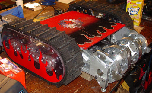
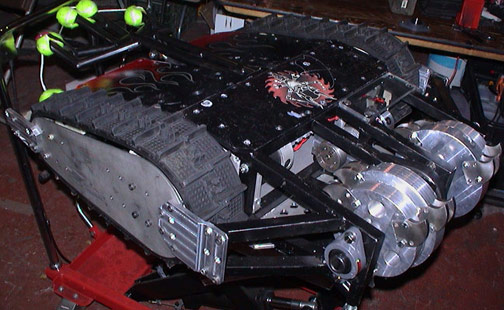