|
Understanding Pneumatics
By Brett "Buzz" Dawson -- Team DaVinci Robotics
With contributions by:
Alexander "Zander" Rose -- Inertia Labs
Disclaimer!
Before we get started I need to stress the dangers involved with working with high pressure pneumatics. It is extremely dangerous if you do not know what you are doing or if you are using components that are not rated for the correct pressures the system could explode causing serious injury and even death. Pneumatics should only be implemented in a robot by an experienced builder or a pneumatics specialist. This section is just designed to help give you an understanding of pneumatics and how it works. That being said, we can get on with the lesson :-)
Note: In this text the cylinder which contains all parts of the pneumatic cylinder (body, piston, end caps, etc.) may be referred to as cylinder or actuator. The movable part of the cylinder may be referred to as the piston or ram.
What is pneumatics?
Pneumatic systems employ gas that is compressed under extremely high pressure. The practical use of pneumatics comes in putting that compressed gas to use, or should I say the use of the rapid expansion of compressed gas. At its most basic level a pneumatic system holds compressed gas in a specially designed tank and then we release some of that gas into an expandable chamber. The expandable part of the chamber has a rod attached to it so that as it expands the rod moves outward. Sounds pretty simple, right? Well, in theory it is, but it is in application that things get complicated.
Parts of a pneumatics system
What a gas!
The first part of a pneumatic system may not sound like an actual part, the compressed gas itself. There are three main gases used in the construction of a robot pneumatic weapon system; Carbon Dioxide (CO2), Nitrogen (N2), and High Pressure Air (HPA). Nitrogen and HPA can be compressed in a tank to upwards of 5000 psi (pounds per square inch) but require larger tanks. CO2 on the other hand liquefies at around 850 psi which allows it to take up less space and therefore need a smaller tank (The actual pressure is dependant upon outside ambient temperature. The note below will explain why but for the purpose of this help section we'll use 850 psi). CO2 exhibits some really unique properties under pressure and when it is vented. Without going into the theories of thermodynamics let's suffice it to say that as pressure drops so does the temperature and lower temperatures create lower pressures to a point of equilibrium. In other words, a drop in pressure results in a drop in temperature but that same pressure will not come back until the ambient temperature rises back to the same point.
When you let some of the gas out of a CO2 tank (or any pressurized tank for that matter [see below]) the pressure inside the tank drops which makes the tank get cold (REAL cold). Well, now that there isn't as much pressure in the tank the liquid CO2 starts to boil. The boiling CO2 releases gas which increases the pressure until there is enough pressure to keep the liquid from boiling any more, which happens to be around 850 psi. Pretty cool, huh? So as long as you have liquid CO2 in the tank, and it is kept at the same temperature the pressure remains at a relative constant.
Note: In an environment like BattleBots where you have three minutes per match there is not enough time for the tank to rise back up to normal operating temperatures after each release of gas. So the tank gets colder and colder which results in lower and lower pressures inside the tank. So, your 850 psi tank at the beginning of the match may only have 400 psi of pressure (or lower) at the end of the match and be covered in frost.
But there is a drawback to CO2 systems. If some of the liquid CO2 gets past your regulator (we'll get to regulators in a minute) then it could boil up and increase pressure in the rest of your system. What's so bad about that? Well, if all of your fittings are only rated to 150 psi and all of a sudden there is over five times that pressure in the system you could very easily blow fittings and seals in the rest of your system. Once this happens you cannot use it again until the seals and fitting are replaced with new ones. Notice I said NEW ones? Never try to reuse blown seals or fittings, you'll likely seriously injure yourself. You can help prevent liquid CO2 from entering the rest of your system by mounting the tank upright so that the regulator is at the top of the tank or use an anti-siphon tank to help keep it to a minimum. Also, having a burst valve rated for your regulated pressure on the regulated side of your system is a very good idea as regulators have been known to fail even under normal use.
So, to avoid problem like that you may want to look into a Nitrogen system like those used by many paintball shops, or High Pressure Air.
Because of the unique properties of CO2 hobby uses of it are measured in liquid ounces and pounds. Nitrogen and HPA are measured by volume. For example, in BattleBots, a lightweight robot using Nitrogen is restricted to 12 cubic feet of air which means that if the tank were to be vented to room pressure the gas would fill up 12 cubic feet.
Let's get tanked
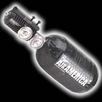 The second part of a pneumatics system is the compressed gas storage, otherwise known as the tank. Tanks range in size, weight, and proofs (rated capacities) depending upon their use. Tanks should be DOT-approved and can be made of steel or Carbon Filament wound Aluminum (like wrapping it with carbon fiber) and will either have the working pressure in psi stamped into the tank or will have a certification sticker on it. Tanks may also be measured in "bar" (not plural). 1 Bar is equivalent to about 14.5 psi which is equivalent to 100KPA which is equivalent to 1 Atmosphere. So a 69 bar tank is equivalent to 1000 psi. Many if not most tanks are many of solid aluminum while there are some that are made of steel. Carbon filament wound tanks can safely handle pressures up to 5000 psi where as a comparable steel tank would be too heavy to use in a robot.
Each tank should also have a burst valve to keep the tank from excessive pressure. In general the burst valve is rated for 120% of the tanks normal operating capacity. If the pressure builds to above 120% of the rated pressure the burst valve will pop open and vent the gas slowly to prevent the tank from exploding. Tanks are generally hydro-tested to twice the rated capacity to pass DOT-approval inspection. Common sources of tanks are welding supply shops, diving shops, paintball stores, and even fire extinguisher tanks!
Regulators
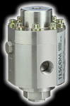 Regulators are interesting pieces of hardware in that they can hold back 5000 psi of air and let only a enough air through to bring the rest of the pneumatic system up to your designed operating pressure. Regulators also generally have a purge valve to allow you to purge all of the air out of a pressurized tank.
Regulators come in all shapes and sizes. Some are rated for high pressure but have a low feed rate. Other have a high feed rate but only work with low pressures. To find one that has a high feed rate and can handle high pressure is tough and usually expensive. The reason that we want a high flow rate is because once the pneumatic piston fires you'll probably want to reload as fast as possible to fire again. The reason that we want high pressure is because our system was designed for a specific pressure and any less than that only degrades performance.
Some regulators will already have gauges to show tank pressure and another to show regulated pressure. Knowing both of these is crucial and in some cases mandatory on your robot.
Note: You should ALWAYS have a way to bleed the system of pressurized air on BOTH sides of the regulator, usually by means of a manually operated purge valve. You never want to get parts of your body near a fully pressurized system.
Buffer Tank
Buffer tanks are not necessarily part of every pneumatic system. But, if you have the extra weight allowance and space available they are very handy to have. A buffer tank is just an extra tank in between your regulator and your valve (which we'll get to in a minute) that stores extra gas. So, what does that do for us? I'm glad you asked!
Let's say that you have a pneumatic cylinder that has a 4 inch bore and a 6 inch stroke. That gives us a total of about 75 cubic inches. Now, let's say that you are using 1/2" pneumatic tubing between your regulator and your valve and on to the cylinder and we are using 250 psi of CO2. If you have 24" of total tubing you have almost 5 cubic inches of compressed air in the feed lines. That will move the piston about half an inch before the regulator has to start feeding more air into chamber. The second the pressure in the feed lines drop below the regulated pressure the regulator starts letting more air through. But what if you have a regulator and is not a high flow kind? Well then your high powered pneumatic flipper just turned into a lifter.
Now, let's put a 75 CI buffer tank in line before the valve. This time the regulator spends a little longer initially filling the feed lines and the buffer tank. But, when you fire the valves the buffer tank dumps its 75 cubic inches of compressed gas along with the 5 that was already in the lines. This time there is a lot more pressure immediately available to the cylinder and we get the "pop" that we are looking for in a flipper. The same amount of CO2 is used both times because we didn't increase the bore or the throw of the pneumatic ram.
Now, we need to remember that the full 250 psi that is sitting in the buffer tank and the feed lines does NOT fill the cylinder instantly. What actually happens is the split second the valves open up is that the system equalizes pressure until the regulator can catch up and bring it up to the full 250 psi. That's the reason that I specifically chose a 75 CI buffer tank for the example. If we have 250 psi at 75 CI and then we instantly double the volume of the system what happens to the pressure? It gets cut in half. So, our 250 psi pneumatic flipper is only using 125 psi at the instant the valve opens. When the piston is fully retracted the pressure is at its highest. As the piston moves forward under the pressure of air the volume increases which decreases the overall pressure (again, until the regulator catches up).
Granted the instant pressure drops the regulator will start feeding more air and thus the cylinder has more than 125 psi by the times it reaches full extension but I just wanted to make a point about the usefulness of buffer tanks :-)
Pneumatic hoses and fittings
Well, for all of the air to move around we need to have a way to move it. That's where the hoses and fittings come into play. To get the best air flow you need to use the largest diameter hose that you can find that is rated for the pressures that you will be using. You will also need to find matching connectors and fittings throughout the system. It does no good to have 1/2" hoses and fittings throughout your whole system only to have a 1/8" port on your solenoid valves (okay, so it's an extreme example but you get my drift). The 'push to connect' low pressure fittings and hoses are the easiest to work with for prototyping and low pressures.
You can get pneumatic hoses and fittings that are rated for very high pressures. You can also use hydraulic lines but they not really good for moving high volume of air in a hurry but some will work. Hydraulic lines and fittings are designed for extremely high pressure and are sometimes sheathed with a steel mesh to help keep the hose from deforming and developing bubbles.
There are some serious drawbacks to using hydraulic rated equipment that should be addressed before we go further. First, hydraulic equipment is rated for 'hydraulics' (duh) and therefore are built to different standards. Hydraulic components are usually metal to metal fittings as that is usually enough to keep a liquid restrained but not necessarily a gas (meaning it isn't 'bubble tight'). This is specially of note with regards to hydraulic valves which, although are rated very high, still use the metal to metal fittings which could allow air to seep through to where it is not supposed to be (yet) and lead to a possible dangerous situation.
It is a good idea to use PTFE (teflon) tape on all threaded connections as it helps seal any gaps that may occur between the threads.
Other miscellaneous things that you will need on your system is a shut off valve and a bleed valve.
Valves
The valve will probably be the most critical (and consequently the most expensive) part of a high power pneumatics system. It has to restrain the pressure built up on one side and be able 'pop' completely open and not restrict the air as it rushes through on its way to the cylinder. There are many types of vales that can be used; Remotely Operated, Manually Operated, and Solenoid Valves. For the context of this help section we will just keep it to solenoid valves.
The reason that it is called a 'solenoid valve' is because there are really two parts; the valve (and valve body) and then solenoid that activates the valve. The solenoid opens a smaller valve that controls a small stream of air that then pops open the large high flow valve.
 There are several different types of solenoid valves but we are just going to talk about the three most common ones used in robots. There is a 3-port, a 4-port, and a 5-port solenoid valve.
The 3-port solenoid valve is so named because it has three ports; one from the tank, one going to the cylinder, and one exhaust. Because there is only one going to the cylinder we will be using a single acting cylinder (It is possible to use a 3-port valve with a double acting cylinder but that gets into advanced design and is therefore beyond the scope of this help section). The valve opens, and pressurizes the cylinder therefore extended the ram. Then the valve closes which opens the exhaust port and the gas in the cylinder is allowed to vent which equalizes it with the outside air and the ram retracts.
A 4-port valve is designed to be used with a double acting cylinder. It has four ports; one from the tank, one to the back of the cylinder, one to the front of the cylinder, and one shared exhaust. In its normally closed position it allows pressure to build up on either the front or the back of the piston depending upon your design. When the valve activates it redirects the compressed air to the opposite side of the piston while simultaneously opening the exhaust port so that the air that is currently in the cylinder can escape. If the air in the cylinder were not allowed to escape then it would just build up pressure when the ram piston tries to move and not allow the piston to go anywhere.
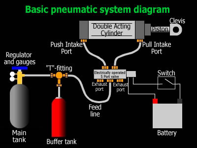
A 5-port valve is also designed to be used with a double acting cylinder but has an added exhaust port. This increases the efficiency of air flow leaving the cylinder which allows it to extend or retract faster. The diagram to the right in this section shows how a 5-port solenoid valve works.
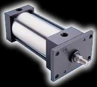
The Actuator
The actuator is the business end of a pneumatics system. All of the parts listed above are to make the actuator (cylinder) move, and move with authority. There are three main flavors of actuators, each with their own advantages and disadvantages; Single Acting, Single Acting Spring Return, and Double Acting. Inside the cylinder is a disc that is sealed against the walls of the cylinder. Then there is a rod attached to the disc which extends out one end of the cylinder. The rod is where we will attach things to to make things move, usually via a clevis. There are end caps on each end of the cylinder to keep the piston from shooting out of the cylinder when the piston slams into it at high speed. Actuators are typically made out of high grade aluminum or stainless steel. There are also a variety of mounting styles.
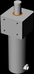
Front Block mount |
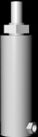
Front Nose mount |
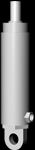
Rear Pivot mount |
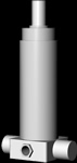
Rear Trunion mount |
A single acting cylinder has only one inlet port and therefore only one power stroke. This is usually at the back of the cylinder so that the power stroke is the 'push' stroke. These require some other means of retracting the piston to its starting position, like gravity. Because of this standard single acting cylinders have a slow reload time. On the plus side it only has one inlet and therefore you get more shots per tank full. Single acting cylinders are more commonly found on flipper bots.
 Single acting spring return cylinders are just like the standard single acting cylinders with the exception that they have a spring inside of them. At the completion of the power stroke the spring helps to push the piston back to its starting position. Like the standard single acting cylinder this one allows you get more shots per tank full than a double acting cylinder and it has the added bonus of a spring return to help speed up reload times. But, alas, it's not all roses. Because there is a spring inside the cylinder it will take pressure to compress it which takes away from power that you could potentially be putting into flipping the opponent. This is usually a minor issue but the bigger issue is the fact that single acting spring return cylinders tend to be longer to accomodate the spring and therefore it makes it a little tougher to fit inside a bot.
The last one is the double acting cylinder. It is called double acting because it has a power stroke on the push AND pull. The picture to the left is of a double acting cylinder and you will notice an inlet port on each end cap. This type of cylinder is used primarily for pneumatic spike bots and hammer bots. The reason that you would want this on a spike bot is because if you get the spike through the opponent you probably want to get it back out, right? Hammer bots are pretty obvious.
Below is an example of how a double acting cylinder is used in conjunction with a 5-port valve. Press the Fire Piston button to watch it in action. Keep in mind that this is a very slow motion example. Robots like Toro can go from rest to full extension in 1/100th of a second. To put that into perspective, in the time that it takes this demonstraion to actuate the piston once Toro could have done it over 200 times!
Uses of Pneumatics in a Robot
Getting Bored
With all of these single and double acting cylinders what is the difference between them? Two things: Bore and Throw. The bore is how large, in diameter the piston is. The throw is how far the piston moves over the course of its stroke. As you will see in the next section the bore has a major role in determining how much force your cylinder will generate.
May the Force be with you
Force is the end goal for everyone using pneumatics. It is what does all the work for us. Force is calculated by the Pressure times the Area. The Area is calculated by using basic Algebra with regards to the Bore. To get the Area we take half the bore and square it then multiply it by Pi (hmmmm... that sounds an awful lot like the area of a circle "Pi(r)^2"). Once we have the Area we multiply it by the pressure to get the force. Here they are again in easy format:
Force = Area x Pressure
Area = (1/2 Bore)^2 x Pi
So, how do we increase the force? Two ways; increase pressure or increase the bore of the cylinder.
Note: If you have been paying attention to all of the diagrams you will probably realized that the bore on the front side of the piston is less than the bore on the back side because of the rod that is attached to it. Believe it or not it does have an effect on the final numbers so be sure to take them into consideration when doing your calculations.
How many shots can I get?
One of the questions that I have heard many times is, "How many shots will I get with 'a' amount of 'gas' in a 'b' sized tank with 'c' psi regulated pressure and a cylinder with 'd' bore and 'e' throw?" Well, to determine that we will need to start with this formula to determine how much gas we have available from the tank:
P1 x V1 = P2 x V2
Note: This formula is known as Boyle's Law and basically states "The volume of a given mass of gas is inversely proportional to the absolute pressure if the temperature remains constant." We will assume for the moment that the temperature does remain constant for the duration of our example.
P1 is your input pressure and V1 is your input volume. P2 is your output pressure and V2 is your output volume. So let's say that we have a 88 cubic inch HPA tank with a 2500 psi tank pressure, 250 psi regulated pressure, and a double acting cylinder with a 4" bore and a 6" throw with a 1" rod to actuate our hammer bot. Lets find out just how much compressed air that we really have in the tank:
2500 x 88 = 250 x V2
220,000 = 250 x V2
220,000 / 250 = V2
V2 = 880 cubic inches at 250 psi
Now, let's figure out how much volume we have in the cylinder using the formula Volume = Area (bore) x Length (throw)
Push Stroke
V = ((1/2 bore)^2 x Pi) x throw
V = ((1/2 4)^2 x Pi) x 6
V = (2^2 x Pi) x 6
V =(4 x Pi) x 6
V = 12.56 x 6
V = 75.36 cubic inches
|
Pull Stroke
Vrod = ((.5)^2 x Pi) x 6
Vrod = 4.71 cubic inches
75.36 - 4.71 = 70.65 cubic inches
|
Now that we have total volume for the push stroke (75.36) and the pull stroke (70.65) we can add them together to get 146.01 cubic inches. Now, we divide that number into the available volume that the tank has:
Remember our formula for determining Force? Let's apply it to determine how much force we are generating on each stroke.
Force = Area x Pressure and we know that we have an area equal to 12.56 square inches on the face of the piston in the 'push' stroke and (12.56 - .785) 11.775 square inches on the face of the piston in the 'pull stroke.
Push Force = 12.56 x 250
Pull Force = 11.775 x 250
Putting all of this information together we get 880 (tank volume)/ 146.01 (total cylinder volume)= 6.02 total shots and reloads (12
total actuations) with 3140 pounds of force on the push stroke and 2944 pounds of force on the return stroke.
So, we get only 6 shots with our uber hammer bot. You can see that you would have a pretty powerful hammer bot but you would only get a limited number of shots. You could decrease the regulated pressure and get more shots with less power or you can go to a bigger tank and get more shots that way if you have the available weight and space.
Just for grins, if we vented the entire contents of the tank into the air how much would that be?
2500 x 88 = 14.5 x V2 (we use 14.5 because that is the pressure at one atmosphere which is normal air pressure)
220,000 = 14.5 x V2
220,000 / 14.5 = V2
V2 = 15,172.4 cubic inches
15,172.4 / 1728 = 8.78 cubic feet (1728 equals one cubic foot of volume)
Note: The above calculations are under ideal circumstances and anyone who has built a robot before will tell you that you NEVER have ideal situations. So, whatever number you get you'll probably get a little bit less.
And lastly, there is no substitution for real world testing! As I have always said, "Numbers look good on paper but you never really know until you build it." And remember to use your head and be safe!
Hey, chill out!
Okay, ready to get into some more math? Remember earlier when I stated that Boyle's Law says, "The volume of a given mass of gas is inversely proportional to the absolute pressure if the temperature remains constant?" So, what happens if we change the temperature? Well, there's a new law that comes into play called the General Gas Law which states the relation between Pressure and Temperature
P1 / P2 = T1 / T2.
P1 = Initial Pressure
P2 = Final Pressure
T1 = Initial Temperature (Absolute)
T2 = Final Temperature (Absolute)
Note: Temperature means "Absolute Temperature". Since the temperature at which molecules stop moving is -460 degrees Fahrenheit, also known as, Absolute Zero, we have to add 460 to whatever temperature above 0 degrees Fahrenheit that we want to work with. This is known as the Rankine Scale. So, 50 degrees Fahrenheit (50 + 460) equals 510 Rankine. With me so far? Okay, let's get back to the math.
Let's put an electric heat wrap on the tank but not turn it on yet. Now, let's say that the ambient temperature in the BattleBox is 85 degrees (trust me it feels like 100 in there :-p) and we have 2500 psi in our 88 ci tank at this temperature. Before the match starts we flip the switch that turns on the heat wrap and (for argument's sake) it gets the tank up to 170 degrees Farenheit. Sounds like we just doubled the temperature so the pressure should be double, right? Well, not quite, remember we are working with absolute temperatures here. So, the absolute temperature at the beginning of the match is really 545. At 170 degrees Fahrenheit the absolute temperature is only 630. Not even close to double the temperature. So, if we apply the General Gas Law 2500 (P1) / x (P2) = 545 (T1) / 630 (T2) we get x = 2890 psi.
Well, now that we have more pressure in the same amount of space I would bet that it would have an effect upon how many shots we can get out of our system. Replacing 2890 for 2500 in the equation above we get 1017.28 ci at 250 psi available to us instead of only 880. If we finish the equation we get a total of 7 (well 6.97 but who's counting?) shots. That gives us 7 foward swings and 7 reloads. That gives us one whole extra chance to smack the snot out of the opponent. Had the answer been 6.5 we could have gotten 7 swings but only 6 reloads so we'd be dragging a limp hammer around the box until the match was over.
Now because we are dealing with BattleBots rules here the Technical Regulations say that a bot can carry no more than 2500 psi of N2 or HPA on board at any time (8.2.2.a of Tech Reg 2.2). This is why it is stated in the Technical Regulations section 8.9.5 Pneumatic Heaters NOT Allowed.
Okay, now that we know that the heaters are not allowed, and we know the relation of Pressure to Temperature, what would the temperature of the gas be after one shot if the ambient temperature of the gas starts out at 85 degrees Fahrenheit? Well, this one is gonna take a little more math because the pressures are different on both sides of the regulator and we need to know how much gas gets used after one shot.
First, lets determine how many units of Atmosphere we have available in the tank by multiplying the pressure by the volume:
2500 x 88 = 220,000
Now let's figure out how much of that gets used up when we fire our weapon. We know that the volume on the push stroke is 75.36 ci and we are running it at 250 psi. Now we multiply those together:
250 x 75.36 = 18,840
So now we now have (220,000 - 18,840) 201,160 units left that are stuffed into an 88 ci tank
201,160 / 88 = 2285.91
We now have 2285.91 psi of HPA left in the tank after one shot. That means that we just dropped in pressure so, by the General
Gas Law, there must be a corresponding drop in temperature of the gas. (Remember to add 460 to the temperatures!)
2500 (P1) / 2285.91 (P2) = 545 (T1) / (460 + x (T2))
1.094 = 545 / 460 + x
x + 460 = (545 / 1.094)
x + 460 = 498.17
x = 498.17 - 460
x = 38.17 degrees Fahrenheit
So, the temperature of the gas dropped almost 47 degrees after just one shot. Now the tank itself won't be that cold because of thermodynamics but that is some serioulsy nasty math that we don't want to get into at this point. Now remember, this is just after one actuation of our cylinder. We still need to reload. So, if we apply the same math to the reload function (I'll let you do it on your own to see if you get the same thing) we get a gas temperature of -5.57 degrees Fahrenheit.
Theoretically, you could work out all twelve actuations and get down pretty close to absolute zero but in reality it never comes close.
Wrapping up
Well, there you have it. A somewhat in depth look at what it takes to build a pneumatics system in a robot. It's not something to be taken lightly but if you have the time, energy, and patience you to can build one of the most exciting bots to watch in the arena. I hope you have enjoyed reading this and hopefully you have learned a thing or two along the way. And, I have said it before and I'll say it again, have fun but please use your head and be safe when building a robot of any kind. Cheers! -Buzz
|

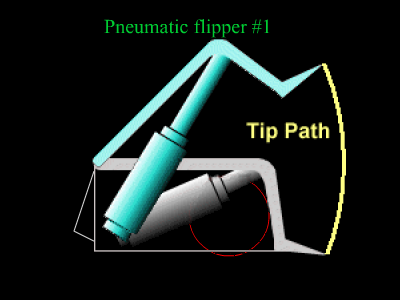 There are many different uses of pneumatics in a robot. First let's look at flipper robots. In the Pneumatic flipper #1 diagram you can see how the gurus at
  The guys over at
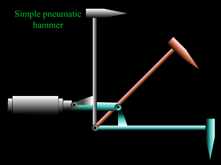
 Here is a little more advanced use of pneumatics in a hammer bot. One of the most powerful, if not THE most powerful, hammerbots is Jascha Little's