Run Amok Combat Robotics EdgeTX Transmitter Programming for Combat RoboticsPrivacy Policy
Transmitters with EdgeTX firmware are remarkably flexible and can adapt to very sophisticated control requirements. Unfortunately, all that flexibility comes with a complex user interface that confuses novices and gives experienced R/C jockeys a bewildering range of choices. For example: you can't simply turn on Elevon mixing – you need to build up a channel mix from the elements available to the transmitter. This takes some thought and planning.
This guide will give a quick overview of EdgeTX control theory and then jump to examples of set-up, tuning, and troubleshooting for standard combat robot layouts. Once you have your 'bot operational you can take time go as deep into control theory as you like.
The illustrations and screen shots in this guide are from a Radiomaster Zorro transmitter set up with Mode 2 stick assignments (throttle on left stick) and an AETR (Aileron/Elevator/Throttle/Rudder) channel order. The LCD screen shots may differ slightly from implementations on other transmitters, but they will be similar.
Almost all of our robot setup will be done on three screens in the Model Setup menu: INPUTS, MIXES, and OUTPUTS. The signals generated by the transmitter sticks, switches, and knobs pass thru each of these three screens before they are sent to the receiver:
A position signal is generated by a stick axis, switch, or knob.
That signal is routed to the INPUTS screen for possible modification before being passed to the MIXES screen.
The MIXES screen allows signals from the INPUTS screen to be combined and directed to effect multiple receiver ports. The modified signals are then sent to the OUTPUT screen.
The OUTPUT screen allows final modification to the direction and magnitude of the combined signals from MIXES before they are transmitted.
I’ve arranged the topics in this guide to mirror the order of progression a robot builder might follow in setting up an EdgeTX transmitter for use. This order differs from the path the signal takes thru the transmitter stages.
Menu Navigation
The EdgeTX menu navigation system uses physical buttons to move between pages, select options, and adjust values. Some implementations feature touchscreens that allow swipe and touch gestures.
For transmitters with buttons and a scroll wheel or dial:
MDL Short press for Model Settings, long press to select a model.
SYS Short press for Radio Settings, long press for the Radio Setup page.
RTN (or Back Button: Returns to the previous page or cancels an action.
PAGE> / PAGE< Navigates between different screens, tabs, or settings.
Roller/Push to Enter Selects an option, enters a particular value, or confirms an action.
For transmitters with touchscreens:
Touchscreen Swiping Swipe left or right to move between different screens.
Tapping on Groups and Shortcuts Tap a group icon to see its members, then tap a shortcut icon to navigate to a specific page.
Quick Menu Tap the X or an open area on the screen to close it.
If you are ever confused or lost, a long press on the RTN / Back button will usually take you back to the main start screen.
Our programming examples take place in the Model Setup menu. Press MDL to open the Model menu.
The Mixes Screen Linking Inputs to Outputs
The mixes screen can combine multiple inputs and route the combined signal to multiple receiver ports, allowing a single input to effect multiple receiver ports. Basic combat robot control typically uses a 'mix' to allow a single transmitter stick to coordinate left and right side drive motors to provide forward/reverse drive and left/right rotation.
A Single-Stick Drive Mix
EdgeTX has no pre-defined mixes – we must define our own. This mix allows the right-side transmitter stick to control steering and throttle. The left motor controller plugs into the CH1 receiver port and the right motor controller plugs into the CH2 receiver port.
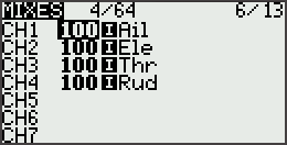
Page across the thru the Model Setup menu to the MIXES screen. Your mixes screen should look like this, perhaps with more channel entries:
Scroll, if needed, to highlight the CH1 line, then long press Enter to bring up an action menu.
Scroll to Insert After and long press enter to bring up a new menu.
Scroll to Source , enter, scroll to Ele , Enter, Return, Return.
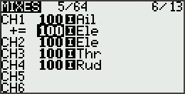
Your MIXES screen now looks like this:
Scroll to highlight the CH2 line, and long-press enter to bring up an action menu.
Enter to select the EDIT menu.
Scroll to Weight , enter, scroll the value down to -100 .
Enter, Return, Return
Long-press enter to bring up an action menu.
Scroll to Insert Before and long-press enter to bring up a new menu.
Scroll to Source, enter, scroll to Ail .
Enter, Return, Return
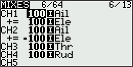
Your MIXES screen now looks like this:
Output Channel on a Switch
Sometimes you don't need the range and precision of a control stick to activate an output channel. Maybe you're just activating a flipper mechanism. A transmitter switch would serve that purpose nicely. Some transmitters may already have output channels assigned to switches, but if yours does not this example will assign CH5 to toggle switch SE :
Page across the Model Setup menu to the MIXES screen. If you already have a single-stick drive mix your mixes screen should look like this:
Scroll to highlight the CH5 line, then Enter.
Scroll down to 'Source', Enter, scroll to !SE.
Enter, Return, Return
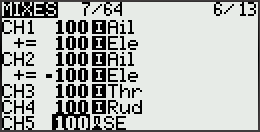
Your MIXES screen now looks like this:
The INPUTS Screen Adjusting Control Response
Time to do some work on the INPUTS screen where we have the option to modify the signal coming from a stick, switch, or knob before it gets to the MIXES screen. We can modify response 'weight', add switches to select between weight options, and even reverse the direction of input response.
Dual Steering Rate Switch
As mentioned in the MIXES section, a 100 Weight assigned to the Aileron input gives too much steering responsiveness for most drivers. The INPUTS screen is the place to adjust that weight.
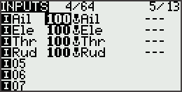
Page across the Model Setup menu to the INPUTS screen. With default settings your inputs screen might look like this:
Use the scroll wheel to highlight the Ail line, then long-press the ENTER button to bring up an action menu.
Enter to access the EDIT screen.
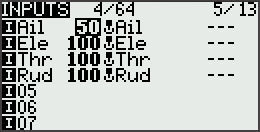
Scroll down to Weight , Enter, scroll to a value of 50 .
Enter, Return, Return.
Your INPUTS screen now looks about like this:
Steering response is now at a comfortable driving level but it is useful to be able to restore full rotation speed for a victory dance or to spin fast enough to flip back upright when inverted. We will add a 'Dual Rate' switch to restore full response when activated:
With the Ail line highlighted, long-press Enter to bring up an action menu.
Press Enter to access the EDIT screen.
Scroll down to Switch , Enter.
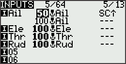
Scroll to SC⇧ , Enter, Return, Return.
Long-press Enter again.
Scroll to Insert After , Enter, Return, Return.
Your INPUTS screen now looks about like this:
How does this work?
If there are multiple lines entered under a single input, the transmitter evaluates the first line to see if any conditions it includes are met. If they are, that line is used. If not, it skips down a line and repeats the evaluation process.
Our first Aileron line has the condition SC⇧ that requires that switch SC be in the ‘up’ position – the position the transmitter expects at start-up. If switch SC is up the line will be accepted and the steering rate will be a controllable 50 .
If switch SC is not ‘up’, the transmitter will skip down to the second line and evaluate its condition. This second line has no condition set, so it will be accepted and the steering rate will be a very quick 100 .
You can choose different values for the Weight to suit your driving preference, and you can choose a different switch. You can also add more lines for additional conditions -- but leave the last line condition free.
A Simple Invert Switch
So far everything we’ve done in EdgeTX has been more difficult than it would have been on a conventional menu-driven transmitter. Why would anyone write transmitter firmware that makes things more difficult? EdgeTX does make simple things a little more complicated, it can make complicated things a lot simpler.
When a wheeled robot is upside-down the steering remains correct but the throttle direction is reversed. Assigning a switch to reverse the response of the Elevator stick axis in a conventional transmitter is somewhere between complex and impossible, but in EdgeTX it's just two lines of code:
Page across the Model Setup menu to the INPUTS screen. With our Dual Rate switch code the inputs screen looks about like this:
Use the scroll wheel to highlight the Ele line, then long-press the ENTER button to bring up an action menu.
Press Enter to access the EDIT screen.
Scroll down to Switch , Enter, scroll to SF⇧ , Enter, Return, Return.
Long-press Enter again.
Scroll to Insert After and Enter.
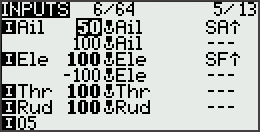
Scroll down to Weight , Enter, scroll the value to -100 .
Enter, Return, Return.
Your INPUTS screen now looks like this:
When Switch SF is up (SF⇧) the elevator response is normal, but when SF is not up the throttle response is reversed. You can of course choose a different switch to suit your preferences.
NOTE Aircraft users program a different type of invert switch because this simple approach does not invert the axis trim setting. Trims are important if you’re controlling servos, but robot motor controllers seldom rely on trims to adjust their center position. This approach should work just fine for your robot. If not, look up the aircraft version on the ‘net.
The OUTPUTS Screen Limiting and Reversing Response
The OUTPUTS screen is the last stop before the signal is transmitted to the receiver. Adjustments made here will modify the magnitude and direction of the signal sent to the specified receiver output port after all mixes have been applied.
Limiting Motion on a Servo
A servo powered lifter might not require the full range of servo motion. Such a lifter may be completely retracted at -75% of servo motion and fully extended at +90% servo motion. We can limit the range that a specific output channel can command and prevent harmful stalling of the servo.
Page across the Model Setup menu to the OUTPUTS screen. With default settings your outputs screen should look like this:
The OUTPUTS screen allows direct limiting of the motion range commanded on each side of the motion center point. Here we will limit servo motion to 75% of normal below the center point and 90% above.
Use the scroll wheel to highlight the CH3 line, then Enter to bring up an action menu.
Enter to go to the the EDIT screen.
Scroll down to the Min line, Enter, scroll to -75 and Enter.
Scroll down to the Max line, Enter, scroll to 90 and Enter.
Return, Return.
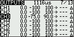
Your screen now looks like this:
Full upward throw on the Throttle stick axis will now provide only 90% of full upward servo motion, and full downward throw will provide only 75% of downward servo motion. No servo stall!
Bonus: Extended Servo Response
By default EdgeTX prevents assigning Output travel values outside the range of -100 to 100 but most servos are capable of responding to signals outside this range to provide an extended range of motion. If you need increased extension from a servo for a small lifter robot, the default limits can be overridden on the Model SETUP screen:
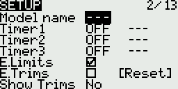
Page left from the OUTPUTS screen five times to find the SETUP screen:
Scroll down to select the E.Limits checkbox.
Enter to check the E.Limits box.
Return, Return.
You may now go back to the OUTPUTS screen and enter Min and Max values over an extended range from -150 to 150. Most servos will jam and stall before they reach 150% of normal range, so use caution in exploring motion limits.
Inverting Response
The robot may respond incorrectly to a transmitter command because motor polarity is reversed or a servo is installed in an unusual orientation. Rather than changing the robot hardware it is often simpler to invert the receiver Output to correct the problem.
In a conventional transmitter there would be a menu to deal with Servo Reversing to sort out these issues. In EdgeTX this function is handled on the Outputs screen. In this example we invert the output of CH2 :
Page across the Model Setup menu to the OUTPUTS screen. With default settings your outputs screen should look like this:
Scroll down to highlight CH2 , then Enter to bring up an action menu.
Enter to access the EDIT screen.
Scroll down to the ‘Direction’ line, Enter to change the mode to INV
Return, Return.
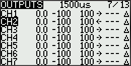
Your screen now looks like this:
The change to the screen is subtle: the little arrow to the right of the ‘100’ on the CH2 line now points to the left instead of the right, indicating an ‘inverted’ response.
Inverting the response of select channels will prove usefull in solving problems uncovered in the next section: correcting drive mix problems.
Troubleshooting Correcting Drive Mix Problems
Find a safe place to test the robot drive, unplug all weaponry, and power up the radio and robot. Try a little gentle forward motion and a slow turn to the right. If everything responds correctly you're done. If something isn't right follow this process:
Given a forward command, only one motor responds -- given a right turn command, only the other motor responds.
You have both transmitter mixing and on-board mixing on the controller turned on. Turn off the on-board controller mixing.
Given a forward command, robot spins in place.
Invert the response ☆ for the channel that feeds the controller for the motor that is backing up.
Given a forward command, robot backs up straight.
Invert the response ☆ for both of the motor control channels: CH1 and CH2 .
Given a right turn command, the robot turns left.
Unplug the controller connectors from the receiver and plug the connector that was in CH1 into CH2 and vice versa.
☆ See the section above: Inverting Response.
Epilogue
There you have it. We’ve only scratched the surface of what EdgeTX can do, but the examples given here will suffice to get all but the most exotic combat robots up and running. Now that you’ve got a taste of how the firmware works you have a good basis to dig thru the documentation for more advanced features, like:
Triple rates
Voice prompts
Logical switches
Exponential curves
How to use the knobs
Q: I want to set up my EdgeTX transmitter for arcade stick style driving: left stick (CH3) controls forward/back and right stick (CH1) controls steering. I understand the steps you give to set-up the single-stick mix, but what would I need to change to make it arcade dual-stick?
A: I drive an arcade set-up, but there aren't many of us out there, friend. The mixes screen will look quite a bit like single-stick -- all we have to do is modify the mix to remove mixing references to CH2 Elevator and substitute CH3 Throttle:
This is what the Mixes Screen looks like with a right single-stick mix using CH1 Aileron and CH2 Elevator:
Changing the mixing references from CH2 Elevator to CH3 Throttle gives us this:
Please send notes for improvement, correction, or clarification to joerger@toast.net.