![Twenty Years of Ask Aaron [Click Me]](pic4/Ten_2.gif)

Privacy Policy
A: Mark J. It's largely a manual process:
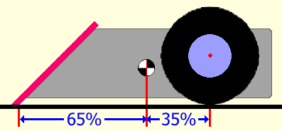
A: Mark J. You've told me nothing about your robot, but let me guess: two wheels set WAY at the back of the chassis and something heavy up in the front. That layout gives very little weight on the drive wheels, and little weight means little traction. When backing, any irregularity in the arena surface will shift what little traction you have to one or the other wheel and cause an unexpected turning motion. Lateral weight transfer caused by the turn locks you in and spins you around. Your problem is entirely mechanical - no transmitter adjustment will help. A two-wheel drive 'bot should have about 2/3rds of the total weight on the wheels for best pushing power, agile response, and good tracking.
Short of redesigning your bot, you can examine the parts in the front of the 'bot that slide along the floor. Polish those contact points smooth and tweek the chassis as needed to assure left and right sides touch with equal weight. If you have the option to move the drive motors forward or shift heavy components rearward you may get some improvement -- but this design error is something best handled when first laying out your component placement.
Take a look at this post from early 2025 from the design archive:
A: Mark J. For best traction you want as much weight on the drive wheels as possible, but leaving too little weight on the front of your 'bot will allow it lift up off the arena floor under acceleration and make it vulnerable to attack. Designing for 65% of the robot weight on the drive wheels gives good traction and leaves enough front weight in most cases.
Note 2 - Magnet downforce may be used to correct traction and lift problems in a steel-floored arena. Combined gravity and magnetic weight of 65% on the drive wheels will still be a good starting point.
Im trying to choose the right brushless motors for the drivetrain of my 30kg combat robot (Its a drum spinner). Im wondering if the "6354 190kv Belt Motor BLDC Motor for On-road and Off-road Electric Skateboard and Robot" would be a good fit for my two wheel drive? our wheels diameter is 25cm (9.843 inches i believe) and the voltage input is 22.2v (Will be using a 6s Lipo batter)
if i need to provide more information then please tell me! Hope this isnt a case of a bad hamburger
Thanks
A: Mark J. From the Ask Aaron Brushless Motor Selection Guide:
Something more like the HobbyStar 4120 (5055) 710 Kv Brushless Outrunner would be close to the low end of the suggested mass range and would produce full power on 6s voltage. Gearing depends on arena size, but a 45:1 reduction (with those 25cm wheels -- why so big?) would give good performance in an 8 meter wide arena.
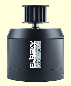 I'm unable to find an exact websearch match for a specific "6354 190kv Belt Motor BLDC Motor for On-road and Off-road Electric Skateboard and Robot", but a pair of generic 6354 motors like the "Flipsky 6354 BLDC Offroad Electric Skateboard Brushless Outrunner" weigh in at better than 1100 grams and require 10s voltage to perform up to their specifications. As power is proportional to the square of voltage, on 6s these motors would have only 0.6 × 0.6 = 36% of the 10s power. Too heavy and too little power.
Q: Hey, person with the 30kg drum spinner again.
Thanks for the hobbystar motor recommendation. Unforunately, i think these are hard to find in my country.
I have a few questions though.
A: It is unusual and limiting to decide on battery voltage before picking drive motors -- I'm glad to hear you're willing to consider alternatives. Let's take a look at the proposed drive motors with the Team Tentacle Drivetrain Calculator: Brushless Version:
A: Mark J. The short answer is "no". PETG is heavier for equivalent strength, more difficult to print, and no tougher than a good quality PLA+. Avoid.
Be sure to check tournament rules for the specific filament types they allow.
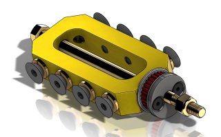 Q: Just a question about beater bar kits. How does the weapon manage keep its axial position along the shaft? Would the weapon be prone to sliding since the needle roller bearings won't resist axial movement? Why don't they use thrust bearings on the sides?
A: Mark J. I assume you're referring to the Fingertech 1-pound and 3-pound beater bar assemblies. These are not "drop-in" weapons -- the design of the weapons supports and fitments are left to the builder. There is typically only a small clearance between the beater and the weapon supports.
For larger robots I absolutely recommend better axial control for any style of spinner, but at the insect-scale it isn't required.
A: Mark J. No competent engineer would spec material thickness before knowing a great deal more about the design and the competition than you have told me.
Q: The college student from Baton Rouge here. I did not provide enough information on that featherweight with a spring-loaded weapon... My bad! Our combat robot competitions differs from regular combat robot competitions. The objective is pushing other robots off a 16 × 16 ft arena, so the primary loading on the chassis is expected to be ramming, sustained pushing, and edge/corner impacts rather than high-energy weapon strikes.
We are planning to fabricate our external armor/frame as a single bent metal sheet of 5052-H32 aluminum, formed on a sheet-metal press brake (bent side, front, and back panels). We chose 5052-H32 specifically for its formability and toughness. We are currently considering 0.080″ thickness, since it is affordable, easy to bend, and relatively light. However, several people have suggested 0.25″ thickness for durability. Given the amount of sheet metal required, 0.25″ would significantly increase both cost and weight.
Based on your experience, is 0.080″ 5052-H32 generally sufficient for this level of combat, assuming a properly designed bent chassis with flanges/gussets? Or is stepping up to something closer to 0.25″ truly necessary for durability in push-out competitions?
A: Warning: Mark is having a rough day and is known for being a bit terse under such circumstances.
Mark J. 5052-H32 is a fairly 'strong' aluminum-magnesium alloy known for being highly ductile and easy to bend. "Easy to bend" is not an atribute you should be looking for in material you will be ramming into hard objects. Armor that deforms enough to lift a wheel off the ground or obstruct its motion is far worse than no armor at all. Certainly 0.080" thick 5052 is unsuitable and 0.25" thick 5052 would - IMO - just be a heavier unsuitable solution. Quite seriously, you would be better off building a box out of good quality 1/4" plywood -- plywood doesn't bend.
Box chassis construction using aluminum top and botton panels with thick UHMW polyethylene side panels and a steel front wedge or 'wedgelettes' is well established in "sportsman class" (no spinner weapons) combat robots around your weight.
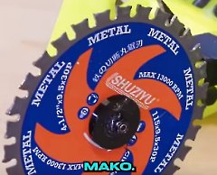 Comment: Hi. Julian here, the builder of Mako.
You previously answered a question about Mako inaccurately and I have been getting a lot of messages asking me about it. I don't use an off the shelf saw-motor or complete setup. I use an off-the-shelf saw *blade*. I specifically use a drone motor with a TPU hub.
I am a big fan by the way, I don't want this message to come off as negative. [Norwich, Connecticut]
Reply: Mark J. I greatly appreciate corrections and clarifications, Julian. The quote from the video I reference in my answer saying that the weapon was "a literal off-the-shelf circular saw that you could walk into Home Depot and buy" combined with the design of your blade retainer led me to an incorrect conclusion -- thanks for writing in to set things straight.
The structure of your weapon hub is now a mystery. If you would care to send in a photo I would be pleased to publish it to provide a complete answer to the question from Zanesville.
 Q: could you help compare High-Density Polyethylene to PCB and carbon fiber? [Hot 'Lanta]
A: Mark J. That's a very general question about three materials with very different properties and uses. It's a bit like asking me to compare a helicopter to a coconut and a dollar bill.
Ask the Google AI to compare high-density polyethylene to garolite and carbon fiber. I just tried that and got a quite detailed categorized comparison. After you study that you will be able to ask me appropriate specific questions about how those materials might best be used for individual components in a combat robot.
 Q: I'm wondering if using a multi-tooth saw (not a commercial saw but a spoked disk with many teeth) attachment as you may recall Silent Spring did in about 2017 or 2018 for a beetle weight midcutter horizontal design would allow me to defeat those "jelly" all-TPU control bot designs. I'm not a materials scientist but my intuition is that TPU's elasticity would let it slightly "flow" between teeth and get ripped apart in a very small area. Meanwhile with a usual single tooth bar, the TPU gets time to flex away and absorb the impact force with its entire volume. Since TPU has low yield strength I doubt it would be hard enough to kick the low-bite saw off of it like an AR500 plate. Since a lot of strain results in very little stress for TPU, stress = F/A, and forces are equal and opposite, I think even though the HS is not constrained like a hammer saw it would be able to maintain extended engagement unlike if I were to attack a hard metal plate with the blade.
Worst case scenario it deals absolutely no damage, which is basically what conventional bar and disk spinners do to those things anyway
A: Mark J. From memory, the sawtooth disk 'Silent Spring' used 2017 had very sharp tips designed to slash into soft materials. Ripping into soft material with sharp blade tips that can "dig in" to the soft surface even at a shallow impact angle is much more effective than using blunt 'spokes' that spend most of their energy in a low bite attack simply tapping your opponent backward. A disc with multiple teeth spinning at several thousand RPM is not going to allow time between impacts for any material to "flow" in between the teeth. Maintaining 'extended engagement' will be still be difficult, as the transferred weapon energy at a low bite angle will act to spin both you and your opponent around in opposite directions.
Take a look at this archived post about attacking TPU plastic with a 'low bite' weapon.
A: Mark J. Eggbeater weapons notoriously create a lot of aerodynamic drag. Assuming that you keep the 14:21 reduction:
A: Mark J. See Frequently Asked Questions #28 for our policy on discussing flame weaponry -- and read the rest of the FAQ while you're there. The flamethrowing beetleweight 'Dutch Oven' is currently ranked 144th in the NHRL standings.
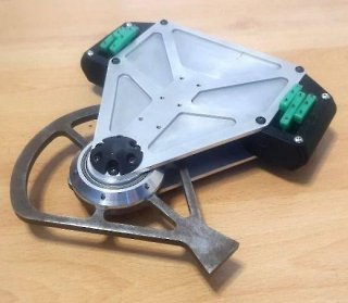 Q: Hi Mark! It's the guy from the "Shore of the Mediterranean" again. Quite a bit of time has passed since my last question and I managed to get second place in one of the two competitions I have attended locally. I lost to the as of yet, still reigning champion (see attached photo) mostly due to my own failings, forgetting to purchase spares and even bring some ready parts.
As for the question, for the next competition I intend on building a multi-bot, since if you can't beat 'em, join 'em. For one part of the multi-bot I would like to have some control based archetype, a four-bar lifter to be exact. Thing is, nobody seems to build them nowadays, direct servo lifters (SSP, Jelly Baby, etc.) seem to be all the rage. Has anything changed in terms of the rule sets or in terms of material/manufacturing/electronics availability that would be unfavorable for a four-bar lifter over a plain servo lifter, or are people just taking the easy route?
Thanks!
A: Mark J. As I recall, your local tournaments have adopted a NERC-style multibot weight bonus. That's certainly an incentive to go multi -- particulary if you're up against sophisticated competitors like your reigning champion.
Four-bar lifters definately have become rare. The current design 'meta' favors more compact single-pivot lifters, structually strong enough to carry attached forks and still withstand spinner impacts. Such lifters also take up less room than 4-bar designs, allowing a more compact chassis layout. I think thoughful design might get you a 4-bar that will overcome these issues.
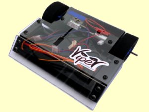 Q: Is the fingertech viper kit underweight? If not, how much weight does it have to sacrifice to use an addon? [Hot 'Lanta]
A: Mark J. Thats very easy to find. Per the websites for FingerTech Robotics, RobotShop, and Palm Beach Bots:
Alternately, you can use the 'Channel Reverse' function on your transmitter to reverse the response of your steering channel (most likely Channel 1 - Aileron). You didn't mention which transmitter you have, but most have this feature. This is handy if you have an "all-in-one" receiver/DESC with no channel plugs (like a Malenki).
I spent a good deal of time creating the Team Run Amok Combat Robot Mixer Fixer -- answer three questions about your robot and it will give you a complete and accurate solution to your mixing problems. Give it a try next time.
 A: Mark J. Yes -- your ESC channels are plugged into the wrong receiver ports. If you are using channels 1 and 2, unplug the receiver connectors and plug the connector that was in channel 1 into channel 2 and vice versa.
A: Mark J. Ask Aaron does not answer questions from builders competing in India.
A: Mark J. I've never actually tried, but it shouldn't be very hard. You can only go where the rails go, so just give it a little throttle and toot the whistle once in a while.

|
Remembering Aaron Joerger, 1991 - 2013
The 'Ask Aaron' project was important to Aaron, and I continue the site in his memory.
Thank you for the many kind messages of sympathy and support that have found their way to me.
Aaron's obituary
|

Q: how can robots help us deal better with hurricanes and why? [Ontario, California]
A: [Aaron] Few people in Nebraska are threatened by hurricanes, so send a swarm of killer robots into low Atlantic and gulf coastal areas to drive the puny human inhabitants toward Nebraska. Problem solved.
Robot haiku:
|
That's obviously A question from your homework. Do your own research. |


how to design and build a battlebot

Copyright 2009, 2026 by Mark Joerger
All rights reserved.


 Even small combat robots can be dangerous! Learn proper construction and safety techniques before attempting to build and operate a combat robot. Do not operate combat robots without proper safeguards.
 Q: What do your combat robots think of the current COVID-19 pandemic? [Kansas City, Missouri]