
Privacy Policy
 Combat Robot Design Tools
from Team Run Amok
Presented here are descriptions, explanations, and links to combat robot design tools developed or adapted by Team Run Amok.
|
This applet opens in its own window and models robot drivetrain performance based on robot weight, motors, operating voltage, gear reduction, and tire diameter. Calculates speed, acceleration, current consumption, and controller capacity requirement. Allows for adjustment of traction conditions and warns of drivetrains that allow drive motors to stall. Allows quick selection of suitable drive components and optimization of drive variables. An example walk-thru of a drivetrain analysis using the calculator is available: Example Drivetrain Analysis using the Tentacle Torque Calculator Updates - There are continuous updates to the calculator. Recent updates include:
| |
|
The spreadsheet calculates weapon mass, moment of inertia, stored kinetic energy, tip speed, spin-up time, and approximate battery capacity requirement. Includes conversion calculations for english/metric units, and a table of common material densities. New to version 20a The spreadsheet now includes an estimate of the battery pack internal resistance in motor torque and current calculations. It retains the brushless controller 'soft start' estimate from version 19e and improves documentation on that process. Download and open as a standard .xlsx spreadsheet. Requires Microsoft Excel Team Run Amok JavaScript Spinner Weapon Calculator Prefer an on-line spinner calculator? This 'lite' version of the full spreadsheet runs in your browser window and calculates weapon mass, moment of inertia, stored kinetic energy, and spin-up time. Like the full Excel spreadsheet, this calculator has been updated to include an estimate of battery resistance in its calculations. Suitable for use with smart phones and tablets as well as laptop/desktop computers. Updates:
| |
|
Frequently Asked Questions about spinning weapon design from the 'Ask Aaron' website. This FAQ provides theory and design advice on energy storage, rotational speed, motor selection, and spin-up time. Additional discussion on spinning weapons is available in the Ask Aaron Combat Robot Weapons archive. This a useful companion document to the 'Team Run Amok Spinner Weapon Excel Spreadsheet' mentioned above. Other Combat Robot FAQs:
| |
|
This Excel spreadsheet defaults to modeling hammers starting from horizontal and swinging up and over thru 180 degrees. Calculations account for gravity but do not include the inertial moment of the motor armature. Graphic output shows time and energy storage thru 180 degrees of rotation, with a text box commenting on the suitability of the selected motor gearing in achieving best actuation speed and maximum energy storage at impact. The new Version 2.3 (March, 2024) includes numeric display of kinetic energy, time to strike, and terminal speed as well as a plot of time and joules. It retains the ability to model hammers with more or less than 180 degrees of swing. Download and open as a standard .xlsx speadsheet. Requires Microsoft Excel | |
|
I've put together animated sketches and discussions of the pros and cons for several little-known spring/elastic flipper layouts that should light up your design imagination:
The 'Choo-Choo' overrunning clutch winder;
Need help with pneumatic combat systems? Understanding Pneumatics -- Pneumatic Tricks and Tips
The constant-torque 'Snail Cam'; The compact 'Slip Gear' ratchet; and The elegant and stable 'Servo Latch' reset. | |
|
Step-by-step instruction on selecting an optimum gear reduction and wheel diameter combination for a combat robot of a given weight powered by specific Permanent Magnet Direct Current (PMDC) motors. Although these instructions may be used alone, this document is intended as a companion to the Team Tentacle Torque/Amp Calculator discussed above. It provides an explanation of theory and equations used by that applet and offers guidance on adjustments required for arena size and unusual conditions. | |
|
This page has links to several topic-specific guides authored by Team Run Amok to assist combat robot builders in selecting, setting up, enhancing, and troubleshooting radio control systems. Topics include techniques to cure radio reception problems, explanation of radio features useful to combat robot operation, definition of R/C terminology, and use of solid-state gyroscopes to improve robot driveability.
R/C Mixer Troubleshooter
Does your single-stick differential mix give odd results? Answer three questions about your mix and the 'Run Amok Mixer Fixer' will tell you exactly how to fix it -- no trial and error! The new version 4.4 adds support for the integrated Malenki Nano DESCs. | |
|
All is not lost. The new Run Amok 4-Bar Lifter spreadsheet calculates and graphically displays the range of motion and torque requirements for front-bar and rear-bar torque-powered 4-bar lifter designs. The user interface will be familiar to users of the T.i. simulator, and the graphic outputs are directly comparable. The spreadsheet will run on any version of Microsoft Excel from the last 20 years or so, but the current version 1.30 (November, 2022) does not display correctly on Google Sheets. Stay tuned. Download and open as a standard .xlsx speadsheet. Requires Microsoft Excel
While building the Team Run Amok 4-Bar Lifter Spreadsheet discussed above I realized that a few relatively simple modifications could produce a related spreadsheet to model the inverted 4-bar mechanism and remove the guesswork. This spreadsheet is the result of that effort. Download and open as a standard .xlsx speadsheet. Requires Microsoft Excel | |
|
The T.i. Combat Robotics website was home to a number of useful combat robot design discussions and tools.
When their website went dark in October of 2015, Team Run Amok gained permission to grab an archive copy of their 'Designing Around the Gyroscopic Effect' page for safe keeping here at RunAmok.tech.
| |
|
K&J Magnetics has an On-Line Magnetic Attraction Force Calculator that will give an estimate of downforce for a neodymium magnet of specific grade, size, and distance from a 'steel plate' floor. They also provide links to their inventory for magnets of the type entered into the calculator.
Example: A round N42 grade magnet an inch in diameter, 0.25" thick, and spaced 0.25" above a steel floor will provide a 3.07 pound downforce.
The K&J calculator also generates a chart you can mouse-over to see how distance above the steel floor effects downforce. Play around with magnet sizes, grades, and spacing distance to get the results desired. K&J magnet prices are good and their selection is excellent.
| |

1) Review the basics of pneumatic system design at the Team Da Vinci: Understanding Pneumatics page. 2) Consider more advanced pneumatic techniques at the Team Run Amok: Pneumatics Tricks and Tips page. 3) The Guide to Designing a Pneumatic Flipper by the builders of Robot Wars competitor 'Hassocks Hog' includes their 'Flipper Calc Excel spreadsheet' that models the performance of a wide range of flipper designs. From the webpage: 'Flipper Calc' is the result of a few months work picking peoples brains and surfing pneumatic suppliers and gurus. I won't pretend that 'Flipper Calc' is a 100% accurate simulation, but none the less it gives a close enough indication of flipper performance.
|

|

Copyright 2024 by Mark Joerger -- all rights reserved.


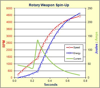 This Excel spreadsheet fully models and graphs the performance of rotary weapons made up of rings (tubes), disks, and rectangular bars sharing a common center of rotation. You may combine elements to make up your weapon such as a ring and a disk to make a 'tuna can' spinner, or you may input a known moment of inertia for CAD cut-out disks or asymmetric weapons. The model accepts any material with a known density, any brushed or brushless PMDC motor with known performance parameters, and any gear reduction ratio. A sample output chart is shown at right.

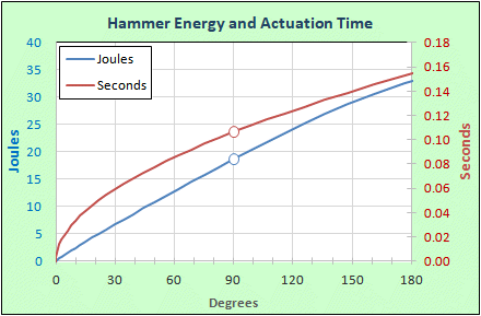 An overhead hammer weapon powered by an electric motor is really just a spinner weapon with very limited rotation. With that in mind I modified the Run Amok Spinner Weapon Spreadsheet to model a hammer swinging thru 180 degrees. I originally wrote this spreadsheet for my own use in talking a builder out of designing an electric hammer weapon, but as hammer weapons are becoming more popular in the 'sportsman' class I thought there might be some general interest in this tool.

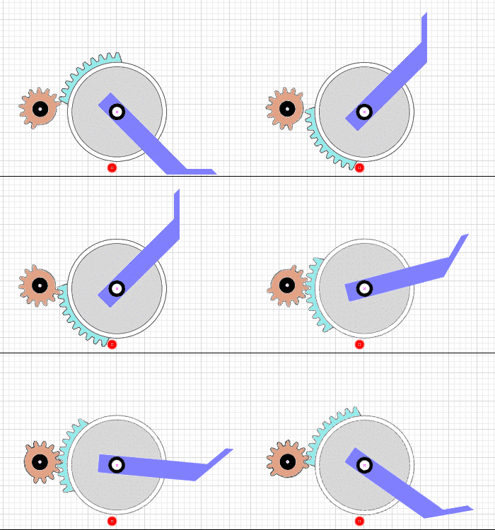 Tired of the same old flipper designs? Having trouble finding insect-sized pneumatic components? Spring powered flippers are awesome, but the rewind and firing mechanisms are poorly known.

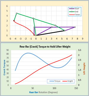 A 4-bar lifter can be an effective combat robot weapon, particularly in the 'sportsman' classes that have limits on spinning weapons. For many years combat robot builders turned to the T.i. Combat Robotics 4-Bar simulator (
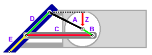 Way back in 2004 Team Run Amok proposed an unusual 'inverted' 4-bar linkage for insect-class combat robots (image at right) that allowed an R/C servo to indirectly power a front lifting wedge via a spring-loaded bar to isolate the servo from shock loading and reduce the servo torque requirement. Servo selection and linkage design optimization for this style of linkage has been guesswork because no existing 4-bar simulator allowed for analysis of the inverted design.


 Are you considering adding some magnets to your robot chassis to gain traction and pushing power in a steel-floored arena? Neodymium 'Rare Earth' magnets are the most powerful by weight and are well suited for combat robot applications, but how do you pick magnets that will give you the desired downforce?
 Want to try your hand at a pneumatic flipper? We have several resources for you: