Four Bar Lifters Powered by
Torque - Amateur
- Adam Wrigley
Last updated - January
2007
DISCLAIMER: Combat robotics is a dangerous sport by it's nature. Extreme caution should be taken when performing any operation explained on this site. Any injury or death resulting from the use of these pages is the sole responsibility of the user and not totalinsanity.net. By undertaking the construction of a combat robot you assume all responsibility for your actions. When building a combat robot, always make sure you are, or are with, a responsible adult.
Build Responsibly.
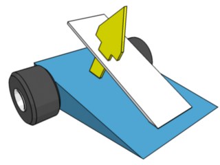
The four bar lifting system is a great way to utilize levers to your advantage. If one examines the two other main types of lifters, the front hinged:
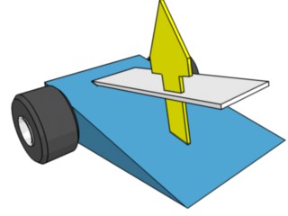
and the rear hinged:
There will be clear advantages to both. The front hinged version will lift the opponent up and away from you. This motion helps to tip the other robot. The problem of course is that you need to have the opponent on top of you, instead of just on the tip of the flipper. The rear hinged flipper requires less "bite" to lift an opponent, but as it lifts, it tends to pull away from the opponent. This can cause the opponent to fall off before tipping over.
The 4 bar lifter has the benefits of both of these designs. It will lift up and out, which will allow for maximum flipper contact through the entire rotation. If you imagine yourself trying to lift and flip a robot with your hands, the trajectory of the 4 bar flipper is extremely similar. Coupled with driving forwards while lifting, the 4 bar can be a great tool in the hand of a good driver.
The 4 bar lifter is an extremely popular design in combat robotics, but much of its design is a mystery to most builders. Optimizing a 4 bar lifter is an extremely arduous task, or at least it was.
Presenting: "Four Bar"
Four Bar is a static simulation of 4 bar lifting systems. It graphs the initial and final positions of the lifter (final position automatically calculated based on max height) as well as a "lifter height & input torque" vs "input angle" graph.
The program works for front, or rear bar powered systems. It is meant for situations where you are powering the bar through torsion to a shaft mounted at the lower link. Do not convert a piston force acting on the front bar to a torque; that is a different situation and will require a different calculator.
The program will tell you the torque that is required to hold a certain weight, at every point in the rotation. Of course, holding a weight is different than lifting a weight. Don't relate the given torque to the stall torque of your output shaft. A more resonable design would use an output shaft with a stall torque twice that of the torque given. This would allow your lifter to actually move at a decent speed, and keep your motors from overheating.
Experiment with different designs, and see what works best. Keep in mind the total rotation of the front bar. Torque may increase, but if the total rotation decreases, then net power required may even out. Some front powered 4 bar systems, like the default values given in the program, will end at "infinity" torque. In reality, this type of 4 bar would simply not extend completely.
Watch the start and end positions to see if there are any binding issues as well (you'll want to avoid any joints going close to 180 degrees). Front bar systems will normally end with the top and rear bar at near 180 degrees. This is normal, but make sure to make your robot, in reality, never go past 180 degrees, or it will be impossible to reverse your arm to close it. In rear bar powered systems, never start with a rear/top bar angle near 180 degrees. You'll notice a starting torque near infinity, which is bad.
As a last note, this calculator only takes into account the vertical force of the opposing robot, not the horizontal force. So, if your system starts moving fast (becoming a dynamic system) then this program will no longer be accurate.
The only defined unit is degrees, degrees must be used for angles. Other than that you can use metric or english units. Torque will come out in the units you input for force and length. If you use meters and newtons, torque will come out in N*m. If you use inches and pounds, torque will come out in in*lbs, etc.
To install the program, unzip the file to a temporary directory and run "setup.exe"
The installation will ask you where it should be installed, and create shortcuts in your start menu and desktop.Four Bar Front Bar is for Windows Systems Only (sorry, I didn't know how to do this in anything besides VB)
Editor's Note: Windows 7 and later versions of the Windows operating system do not directly support .NET Framework 1.1 required by the T.i. Four Bar simulator. Computers running modern versions of Windows can use the Run Amok 4-Bar Lifter Spreadsheet.Download Link (897 Kb Zip File v2.0.7)
© 2006 by T.i. Combat Robotics unless otherwise noted.