

|

Privacy Policy 

The animated drawings are laid out to provide a clear demonstration of the working principle for each mechanism. Some components (like the springs) have been left out or 'implied' to give a cleaner drawing, and the proportions of the designs have been selected for graphic convenience. The layouts are not intended to represent ideal or even workable models for real world implementation. Use them only as starting points for your design.
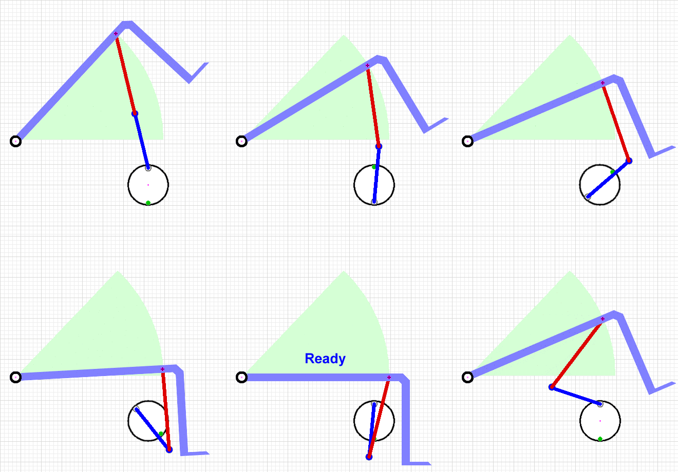
 The 'Choo Choo' flipper mechanism was developed in the FIRST Robotics Competition with several teams contributing to refinements. Robo Raiders FTC 7129 video.
The mechanism is also used for the spring flipper in BattleBots competitor 'Tantrum': descriptive video. Advantages The mechanism is compact and provides a good pulldown distance for its size. The release uses an 'overrunning clutch' principle that does not result in wear along an edge that 'slip' release mechanisms have. Disadvantages The torque loading on the gearmotor is highly variable during the pulldown, resulting in a slower reset time for a given spring geometry and motor than other designs. The 'ready' point is unstable; an impact can set the flipper off unless an additional lock is included. Resources See Apalrd's Choo-Choo Analysis w/Spreadsheet and my key diagram for Apalrd's spreadsheet.
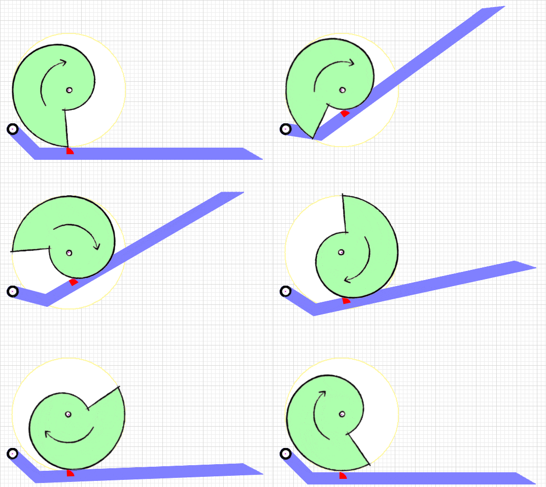
 The deceptively simple 'Snail Cam' mechanism has seen limited use in robot combat to date, and only in insect-classes.
Advantages A properly designed snail cam will keep the torque load on the gearmotor constant thruout the reset cycle, resulting in a quicker reset time with less motor effort. The 'ready' point is a stable flat or detent on the cam that requires no motor torque to hold in place. The snail cam itself can be crafted from plastic using standard shop tools. Disadvantages Sliding friction between the cam and cam follower can be considerable. Crafting the cam from a low-friction plastic like UHMW polyethylene will keep this manageable, and a needle bearing cam follower can completely eliminate the problem. Resources I've published a collection of info on designing snail cams and their associated flipper mechanisms: The Snail Cam Files. The page links to a spreadsheet that will assist in the design of the snail cam and in selection of a cam drive motor.
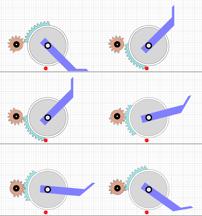
 I like simple design and you don't get much simpler than a slip gear. The key drive components are off-the-shelf gears from which selected teeth have been ground away. The result is a very compact mechanism with a very high angle of potential 'slip'.
Advantages The mechanism is simple and easy to construct. A large range of motion is possible -- large enough for an electric hammer weapon. Disadvantages The gearmotor must hold against the full force of the flipper in the 'set' position. This can be accomplished with a worm drive gearbox, a ratchet mechanism, or a one-way bearing on the gearbox. The 'last tooth' that holds the flipper 'ready' is a point of wear; extra wide gears will extend the operating life.
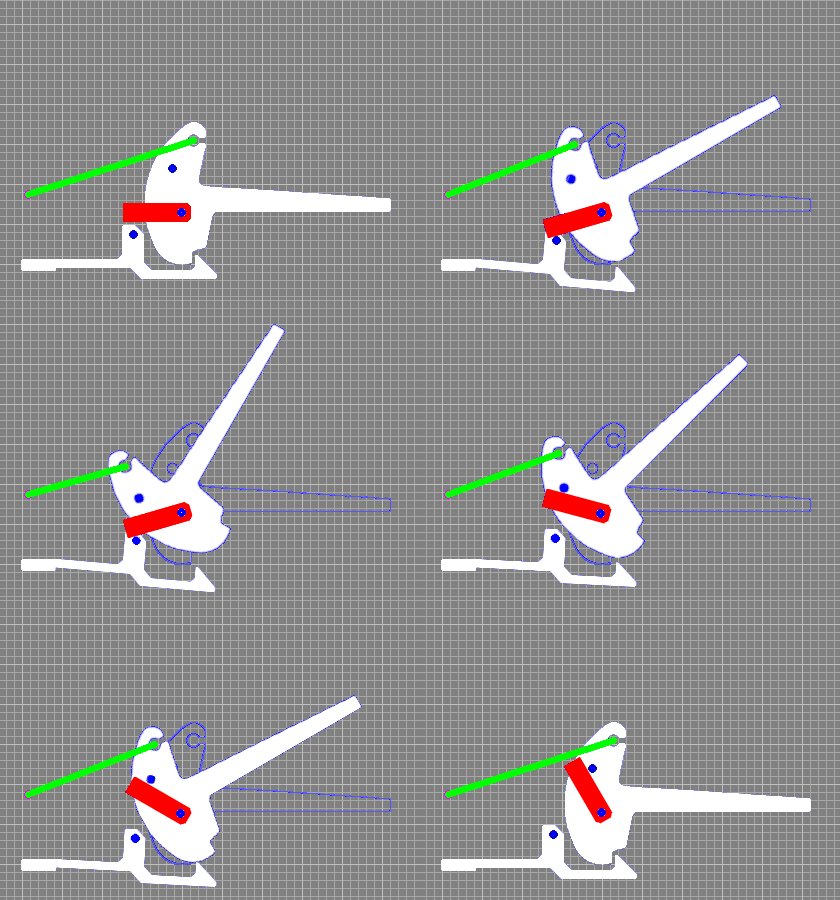
 This is an animation of the actual design from UK antweight 'Militant'. The flipper is triggered and reset by servo. The green line represents the elastic bands used to provide tension, and the red rectangle is the servo arm. The flipper arm pivots on an axle that is separate from but coaxial with the servo output. The servo itself is not shown to better display the release/reset action.
To trigger the flip the servo arm moves downward from its rest position to contact a metal pin extending from the catch arm. The plastic catch arm deflects downward, releasing the flipper. To reset the flipper the servo arm moves upward to contact a metal pin extending from the flipper arm. The servo continues upward, pulling against the elastic and rotating the flipper arm back to the latched position. The servo arm then returns to the rest position. The mechanism is simple and elegant, but the force placed on the servo increases as it approaches the latched position. Moving the servo off-axis to allow the flipper pin to slide closer to the servo axis along the servo arm as the reset progresses could correct this drawback and reduce the required servo force. A more complete analysis of the 'Militant' flipper - with photos - is in this archived 'Ask Aaron' Ants, Beetles, and Fairies post.

Copyright 2018 by Mark Joerger -- all rights reserved. |