Questions and Answersabout Combat Robotics from Team Run AmokPrivacy Policy
This page is one of several archives of 'Ask Aaron' questions and answers categorized by topic. To see the most recent questions or to ask a new question, go to the Ask Aaron Home Page.
Take a tour of posts in this Ask Aaron Archive that have been referenced to answer new questions. Click the 'Mystery Post Tour' button above to get started.
Date marker: January 2026
Walk into Home Depot
Q: Hi Mark,
I was watching an NHRL stream and was interested in a beetleweight (3 lb) overhead saw robot called "Mako". I was having trouble figuring out how exactly the circular saw was mounted to the weapon motor, as it appears to be held on only by a TPU hub and lock nut (no screws or fasteners threaded directly into the motor. Any feedback is greatly appreciated. [Zanesville, Ohio]
A: Mark J. My original answer to this question appears in the box below, but Mako's builder wrote in to clarify the information given in the cited video. Julian Papasian's correction appears below the box.
Mako's weapon is not the usual hobby brushless outrunner with a printed hub like 'Cheesecake'. As disclosed in this video Mako's saw is "...a literal off-the-shelf circular saw that you could walk into Home Depot and buy." It's likely a 4.5" cordless framing saw torn down to just the motor and hub.
Circular saws have blade mounts that look just like what I see in the photos. What appears to be a TPU hub in one photo is likely a polished version of the metal retainer that is catching yellow reflection from the printed chassis.
Comment: Hi. Julian here, the builder of Mako.
You answered a question previously about Mako that was inaccurate and I have been getting a lot of messages asking me about it. I don't use an off the shelf saw-motor or complete setup. I use an off-the-shelf saw *blade*. I specifically use a drone motor with a TPU hub.
I am a big fan by the way, I don't want this message to come off as negative.
Reply: Mark J. I greatly appreciate corrections and clarifications, Julian. The quote from the video combined with the retaining structure on your blade led me to an incorrect conclusion -- thanks for writing in to set the record straight.
The structure of your weapon hub is now a mystery. If you would care to send in a photo I would be pleased to publish it to provide a complete answer to the question from Zanesville.
Jumbo Can-o-Worms
Q: One of the more common lifter setups in insect classes is a rear hinged lifter arm with some sort of 2 part linkage further down the arm providing the lift (Compared to the servo horn providing torque right at where it's hinged). This allows for a greater range of movement for a longer arm.
However my maths is failing me (See bad drawing attached for definitions of symbols). For calculating the force on the lifter arm from the servo in the setup is it as simple as x*sin(theta)? However isn't that just the force transmitted between the servo arm and the arm of the linkage? What about transmission of force between the arm linkage and the lifter arm itself? Are there further losses there?
And then to calculate whether you can lift something or not, is it (F * y) - (W * z) (Where F is the force from the lifter motor on the arm, W is the weight of the robot being lifted, y is the distance between pivot and lifting point and z is the distance between pivot and robot being lifted)?
Hope this makes sense
Thanks in advance. [Somewhere around Manchester, England]
A: Mark J. You've opted to open up the jumbo can-o-worms, eh? What you have is known as a 4-bar mechanism, and the calcs are especially nasty because the lever advantages keep changing as the lift progresses. In your sketch the initial advantage is poor and a good deal of torque is needed, but as theta increases the advantage improves and less torque is required. The general approach is to calculate the actual rise in the tip of the lifter for each change of say 1 degree of servo arm motion and convert that into a torque requirement for each progressive angle.
I know this because I wrote a pair of 4-bar Excel spreadsheets that perform these calculations for standard "Biohazard" style 4-bar lifters (movement up and forward) and for the servo linkage you describe (single pivot hinge motion). That is the good news.
The spreadsheet I wrote for the servo-powered single-pivot lifter has the correct geometry for your purpose, but the example layout has a hinge point much farther forward than your design. You will need to adjust bar lengths and angles to morph into your longer rear-hinge design. This may well take some time. Here are the spreadsheet link assignment letters as they apply to your sketch:
Give it a shot. If the calculations balk, you can wade thru the "Equations" tab on the spreadsheet and make adjustments as needed. Download the Team Run Amok Servo Lifter Spreadsheet from our Combat Robot Design Tools page.
About Eighty Grams
Q: what motor to use for a beetleweight eggbeater robot [Barnet, United Kingdom]
Q: Hi - I'm building my first UK antweight robot, which is a giant 50g bar overhead spinner, with inspiration from robots icewave, moros and bloodsport. It's 2WD, with the brushless motor in between the two drive motors, and a screw in the back to put the blade at an angle. My problem is so: When testing the drive, it's completely fine, when testing the weapon, it's also fine. When I drive and spin the weapon, the robot is incredibly unbalanced, and pings around my test box like an air hockey game.
Could you give me some tips on how to make it balance better? (Also the weapon bar itself is balanced.)
Cheers! [Eaton, England]
A: Mark J. That's a very pretty 'bot with a lovely spinner bar, but you've changed a critical design element from the robots you credit as inspirations. That change is causing your problem.
The spinner bars for 'Icewave', 'Moros', and 'Bloodsport' are all precisely horizontal -- the rotational axis of the weapon remains pointing straight up when the robot turns. You have elected to place "...a screw in the back to put the blade at an angle." That angle causes the direction the weapon axis points to change when the robot turns. Combined with the huge rotational inertia of your weapon this causes a strong gyroscopic reaction, which raises one side of the 'bot, which then causes additional changes in the weapon axis, which then... you get the idea. This is why you don't see angled horizontal spinners.
There is no fix other than tilting the spinner axis back upright and making sure it stays like that. 'Bloodsport' and 'Icewave' are four-wheeled chassis to help keep their blades 'flat' while 'Moros' is two-wheeled but has the center of mass well back toward the trailing rear skid for stability.
Yes, setting your bar fully horizontal raises the weapon up too high to be terribly useful. Call it a rookie mistake. Do not be tempted to 'droop' the impactor end of the bar -- that causes a different type of instability.
Resetting the Rat
Q: Has anyone tried to make a robot like 'Rat Amok' with a 'Snail Cam' (second of four designs on our Spring Flipper Designs page)? A rat trap with a near infinite number of resets sounds very effective.
- sincerely, Iceywave [West of San Antionio]
A: Mark J. I'm quite proud of 'Rat Amok' -- she is a one-of-a-kind antweight that won her first tournament and was later victorious at the "King of Robotica" match between myself and season two champion Mike Konshak with a clean OOTA ejection. Her one-shot weapon struck fear into her opponents, and the suspense of "when will it fire?" added much to the drama of her matches.
A 'snail cam' mechanism is quite bulky due to the large spiral cam. It would be difficult to translate the linear motion of the cam follower into a 180 degree rat trap reset. I suspect this is why no one has attempted a snail cam version of 'Rat Amok' -- but your question got me thinking...
I just now took Rat Amok off the shelf and measured the torque required for a reset against the torsion springs. A full 180 degree reset requires an initial torque at the axle of 12 kg-cm that rises to 29 kg-cm at the end. That is well within the capacity of high-torque R/C servos that weigh about 2 ounces and have up to 270 degrees of motion.
Rather than a snail cam, I believe that the 'Servo Latch' (fourth of four designs on our Spring Flipper Designs page) would be more easily modified to reset the trap, latch it, and trigger the release. Might be fun!
Too Tight for a Gearbox
Q: My design for an antweight full body spinner is very tight on space. I don't have room for regular gearmotors, even the little N10 size, and I can't find any right angle gearboxes small enough and fast enough to work.
Are there any alternative drive methods that might work in such a small space? [Social Media]
A: Mark J. I dug thru the Ask Aaron Archives and found a post from 2016 that described a couple unconventional combat robot drivetrains that require no gears, pulleys, or sprockets:
Friction drive The shaft of the motor presses directly against the surface of the tire and relies on friction to transmit power to the wheel. You will get some slippage, but if your motor has a 2mm to 3mm shaft the reduction ratio works out about right.
Tiny wheels If direct-drive for a normal sized wheel isn't practical, how about a really tiny wheel? Mount a very small wheel to the motor shaft and mount the motor at an angle to put the wheel in contact with the floor. Unconventional, but a successful antweight full-body spinner used this method as a space and weight-saving measure. The 'wheels' could be something as simple as a small plumbing washer, a short length of small diameter rubber tubing, or even a few layers of electrical tape wound around the shaft. They won't last long, but they're easy to replace.
About So Big
Q: What is the usual size of an 'insect sized' arena? [Lagos, Nigeria]
A: Mark J. A common size for beetleweight competition is 8' by 6'. One-pound antweight arenas are often 4' by 4'.
Here is a YouTube video covering the design and building of a 4' by 4' antweight arena with a link to a parts list and design drawings.
Malenki Weapon Voltage Boost
Q: I would like to get more power from my fairyweight spinner, but I use a Malenki-Nano dual ESC/receiver that limits me to a 2S lipo battery. I don't need more drive speed but my spinner waepon would be much better at the higher voltage. I know there is a high voltage version of the Malenki but is there anything I can do that will allow me to run my Malenki-Nano on a 3S battery? [Social Media]
A: Mark J. There is a similar situation that involves operating a lifter servo weapon at 2S when it is plugged into a receiver that can take no more than the voltage from a Battery Eliminator Circuit (BEC). The two situations have similar solutions.
With your Malenki, it is possible to use a battery with more than 2S to provide power to your brushless ESC by tapping into the balance plug of the same battery to obtain 2S power for the ESC/receiver and your drive motors. A diagram for a 3S battery is provided below.
There are a few drawbacks to this solution:
You will need to switch
S
the positive leads to both the weapon ESC and to the Malenki. DO NOT ATTEMPT to use a single power switch on the ground wire! Removing the battery ground causes a 1S reverse voltage to both the Malenki and weapon ESC.
Make certain to use the same ground potential for both the Malenki and the weapon ESC. See this archived post for details.
The three battery cells will not drain at the same rate. Balance charge the battery every time.
More Than You Need
Q: Could a spring from a typical rat trap be repurposed into an antweight flipper?
- sincerely, Iceywave [West of San Antonio ✪]
A: Mark J. Sincerely? I suspect you're just prompting me to post a pic of Team Run Amok's infamous antweight snapper/crusher/flipper 'Rat Amok'.
In truth a rat trap can store far more energy than is required for a properly designed antweight spring powered flipper -- a mouse trap spring should be adequate. I found an analysis on the energy stored in a typical mouse trap at the Physics Stack Exchange:
I calculated the torsion constant in a Victor Original Mousetrap with a spring arm length of 4.3cm) to be approximately 0.09088 N×m/Rad by using Hooke's Law and comparing the angle between the spring arm and the wood base when hanging different weights from the arm with the trap upside down.
I then used τ = -kθ (torque applied to the spring arm by the weight is equal to torsional constant times the angle rotated) along with the values from one of the weights to calculate how far the spring is twisted by default [θ = (τweight / k) - θweight ]. This came out to about 73.63°.
I used this 'starting angle' to calculate how much potential energy (U = 1/2kθ2) the spring would have when totally open (an additional 180° from that last angle we found). The maximum energy that you could get out of this "standard" mousetrap is approximately 0.815 J.
Using the potential energy calculator at OMNI Calculator reveals that 0.815 joules -- if perfectly converted to vertical speed -- could loft a 1-pound object just over 17 feet straight up.
Think Wider
Q: Do people still use the FingerTech S3M belt at Beetleweight? I am working on a horizontal spinner but I don't know if the belt would be able to survive. [Sacramento-ish]
A: Mark J. The 4mm wide S3M FingerTech belts are uncommon in beetleweight spinners -- particularly for a belt long enough to reach out to a horizontal weapon. The S3M tooth profile is OK but the magnitude of the power transfer calls for a wider belt:
The EndBots 'Vector' horizontal bar spinner beetleweight kit used a 0.25" wide (6.35 mm) XL profile timing belt.
For their 3lb Beater Bar assembly FingerTech uses a wide S3M pulley that accepts up to a 8.25 mm belt.
The vertical Peter Bar Weapon Kit from Repeat Robotics uses a 9mm wide 3M profile belt.
The Spec Sheet is Wrong
Q: Why is my drivetrain supposedly so close to stalling? If I drop the voltage to 11.1V then it's apparently going to be unable to drive even though I've run these motors on a Fingertech beater before at 3S. Motors in question are the generic 22mm gearmotors available on the Fingertech site. [Arlington, Virginia]
A: Mark J. You have correctly entered the motor specs given by FingerTech (and other sources) for this motor -- but those specs are incorrect . Per the spec sheet, the 12 volt stall torque for the gearmotor is 27.8 oz-in @ 4.9 amps (Kt = 5.67) but actual test results from multiple builders yield an average stall torque almost three times greater.
For comparision: At 12 volts, the very much smaller FingerTech Silver Spark 22:1 has a similar no-load speed and stalls at 22.7 oz-in @ 2.1 amps for a Kt of 10.8 -- the spec for the 22mm stall torque is obviously too low. See: Converting Motor Specs. Based on the real world numbers I estimate the torque constant for these 22mm gearmotors at 16.3 oz-in per amp. Plug that into the drivetrain calculator and your output will make sense.
Also, the "Torque (per motor) to spin wheels" calculation in the drivetrain calculator does not refer to the torque required to simply drive the robot across the arena. It is the torque required to provide the full pushing force and "beak traction" to spin the wheels and prevent motor stall under heavy pushing. This value should ideally be attained at no more than half the stall amperage of the drive motor. See the Optimizing Drivetrains page for a full explanation.
PS: How much leftover battery life should I pack? The spinner weapon spreadsheet tells me that I'll be using 1.03 amp hours per match, so would a 1500 maH battery work? How do I know if the margin is too small, and if the battery will start to die before the end?
A: The Spinner Weapon Spreadsheet provides a gross estimate of the battery capacity required to spin up your weapon a specified number of times and maintain top speed for the given duration of the match. Take that number with a grain of salt. It does not factor in things like excessive aerodynamic drag from spinning a weapon at stupid-fast speed. It also does not include the battery capacity required by the robot drivetrain.
Generally, rounding up capacity in the 25% to 50% range is about right. You will find out if the margin is too small by testing. Most battery chargers will tell you the mAh required to restore the battery to full charge after a match so that you may determine if the battery has too much or too little capacity.
Literal Top Post
Q: In a beetleweight bar spinner design driven by a timing belt, is it good to have one pulley be smooth? This robot seems to do that, and it would definitely make CAD work easier if I can just use a fingertech toothed pulley for the weapon and fit a smooth 3D-printed one (more appropriate for my CAD skills than a full-on timing pulley) around the motor can.
Three Minutes Later...
Just realized that the literal top post [on the Ask Aaron page] answered my initial question, oops. Do I need to worry about tensioning with one smooth side using a fingertech belt? [Ashburn, Virginia]
A: Mark J. If you run two toothed pulleys you can run a calculated fixed pulley spacing and be fine. If you have one smooth pulley you will need some method of tension adjustment -- one or two tensioning idlers as in your example photo or perhaps adjustable weapon motor mounts.
Beetleweights are still small enough to consider running two toothed pulleys with a timing belt -- you can do that and avoid the tensioning issue. Take a look at the STL files for the EndbotsVector Beetle kit. You might find it easy to modify the motor can 0.25" XL pulley from the Vector to fit your weapon motor. Consider battle hardening your weapon motor if you choose to do this.
Increases with the Cube of Speed
Q: These weapon performance numbers [at right] from the Run Amok Spinner Weapon Energy Calculator are looking a bit optimistic. I used ChatGPT to calculate the internal resistance of the SunnySky 2450 Kv 2212 motor since they only have the specs up to 1400 Kv version on the site.
I'm guessing aero forces will be the limiting factor here and overload the motor, but can you weigh in on how this weapon would perform? Would it be better to go with a lower kv? [An iCloud Server in New York]
A: Mark J. I recognize those weapon numbers. You either have or are duplicating a Vector beetleweight kit. The Vector had the 980 Kv SunnySky 2212 weapon motor that would draw a continuous 8 amps @ 14.8 volts to overcome the aerodynamic drag at 6500 RPM (370 joules). That's about 90 watts and the motor is rated for a continuous power output of 385 watts -- it could do that all day.
You are correct in worrying about aero forces at high RPM. Increasing weapon speed increases aerodynamic drag with the cube of speed:
Doubling the speed requires 23 = 2 × 2 × 2 = 8 times the energy; so...
Doubling the speed of that 6500 RPM weapon to 13,000 RPM (5000 RPM below your target speed) would require 90 watts × 8 =720 continuous watts to overcome aerodynamic drag; but...
The 2450 Kv SunnySky 2212 has a continuous power rating of only 450 watts; which means...
The motor will not hit those performance numbers and it will melt trying.
The output for the same weapon from the full Run Amok Spinner Weapon Spreadsheet (below) shows that you can probably get away with using the 1250 Kv version of the SunnySky 2212 at 14.8 volts to push the weapon speed toward 8000 RPM (520 joules) at a continuous 15 amps @ 14.8 volts. That's about 220 watts with the motor rated at 518 watts. If you want more than that you'll need a larger motor with a higher continuous output limit.
Press Fit
Q: How do robots like Sauron and Vector design their pulleys to fit around the outrunner can? Do they just build it with equal diameter and press fit it on? [Ashburn, Virginia]
A: Mark J. Typically, yes. Actually the pulley inner diameter is a few thousandths of an inch smaller than the can diameter for a tight press fit. See this post in the Ants, Beetles, and Fairies archive for a photo and a link.
Too Squishy
Q: Hi Mark,
I have been pondering the usefulness of tangential drive for antweight (1 lb) applications, but have concerns regarding its compatibility with foam wheels. In particular, the Repeat Robotics Repeat Tangent motors seem to be effective on the likes of robots like "Super Space Turtle", but I have only seen them used with tires made via custom-molded polyurethane/rubber. Could it be that foam wheels are too "squishy" to create any meaningful contact points with the shaft or simply have a poor friction coefficient (if the latter, could this be mitigated using liquid latex/some other traction coating)? This seemed like a "too good to be true" lightweight 4WD solution. Any feedback is greatly appreciated. [Zanesville, Ohio]
A: Mark J. You are entirely correct to worry about this, Zanesville. Tangential drive (YouTube video) and squishy foam tires do not mix. The transfer of power from the drive shaft to the tire is the product of the coefficient of friction and the force by which the shaft is pressed against the tire. Power in excess of this power limit results in slippage, and getting enough force against a foam tire will depress the shaft so deeply into the tire that drive force vectors would no longer be 'tangential' and power transfer efficiency plummets -- with or without a traction coating on the tire.
Note that pressing hard against a tire may place considerable side-loading on the motor shaft. This is a type of load that most hobby brushless outrunners are not designed to accommodate.
Note also that the tangential drive video linked above has the test bed operating at low power and not doing any high-resistance pushing. Gears don't slip under high loading, but friction drive can. I like gears.
Extra Credit: A tangent-drive antweight with 2.0" diameter drive wheels has a calculated top speed of 12 MPH. If the drive train is modified to accept 1.5" wheels, what will the calculated top speed of the robot be?
16 MPH
12 MPH
9 MPH
8 MPH
The calculated speed is still 12 MPH. With a tangent-drive one motor revolution moves the robot forward by one shaft diameter -- wheel diameter is irrelevant.
Stubby Shaft Solutions
Q: I'm a new bot builder trying to build an ant for the first time entirely on my own. I'm planning on doing a servo four-bar lifter and I'm planning to use four 30.4mm diameter 14mm wide LEGO tires. I'm curious about what you'd recommend for the drive motors to go with those wheels, given that the robot is a control bot. I've only build heavily aggressive horizontals before so it's a little different.
I was thinking n20s/30s (but I could totally be wrong) but all the ones I can find that actually have specs have a mere 8.6mm long shaft. Is there a good way to use those short shafts in a wheel that is nearly double the width? I see people all over using them with little to no issues but every time I have tried to it has not gone well because the shaft was wobbly because it was just not long enough. [Purdue, University]
A: Mark J.Good quality N20 gearmotors would have ample power for your control ant, but the gearboxes are potato chip fragile. In the 150 gram class they're fine, but even with wheel protection they don't survive well in full combat one-pound ants. For full combat I can't recommend anything without a stout planetary gearbox -- something like the Repeat Robotics Brushed Mk2. They are larger and heavier than N20s, but two would be enough.
If you're building for the plastic ant class you could certainly give N20s a shot. If you do a web search for N20 long shaft you'll find multiple choices for both threaded and smooth shafts in assorted lengths. The pictured example (fingers for scale) from eBay has a 23mm long shaft. Cheap eBay N20s typically have low-power motors, but you can swap in the high-power carbon brush robot motors if needed.
I must note that it is unusual to first pick your wheels and then design the drivetrain around them.
Date marker: January 2025
Raising the Roof
Q: How effective would adding spacers to shock mount the lexan top panel be to counter the new, devastating hammer saws like Strikepoint in the beetleweight class? (On a 4WD wedge) Although having the armor resting above the chassis would lead to a less than ideal outcome against horizontals that manage to rip into the gap, I figure that it would buy me a few hits against overhead disc spinners and saws by giving it some distance away from the electronics. [Behind a Cloudflare Curtain]
A: Mark J. Any specific guidance I might give would depend on design details you have not provided. Beetle, 4WD wedge, Lexan top panel -- are we talking about a BotKits D2? General comments:
Lexan (polycarbonate) gets much of its strength from its ability to flex and stretch. Think of it as stiffened transparent rubber.
Lexan cracks and fails when it is fastened in a way that concentrates the stress of flexing to a small area. I typically recommend oversized mounting holes with rubber grommet inserts to allow some 'give' around the fasteners.
Raising a top panel on small spacers removes the support of the chassis edges and increases stress around the fastening points. The added height also increases stress on the fastening screws. You haven't mentioned how much additional space you are considering.
Is damage from overhead weapons something your 'bot has actually experienced, or is this speculation on your part? If this is an actual problem I might suggest simply replacing the top panel with something that does not flex enough to endanger your internal components: carbon fiber, garolite, or perhaps thicker Lexan.
You Already Have Gearboxes
Q: I want to get my D2 beetle running again, but I want to use something stronger than the generic Botkits 22mm gear motors to stay competitive and I can't get the Botkits motors to last on 4S. The Just 'Cuz Dragon 22mm Dartbox Gearmotors look great, but the weird clamp drive motor mounting system the D2 uses won't work with a square Just 'Cuz gearbox.
Any alternate recs for good 22 mm brushed gearmotors? [Social Media]
A: Mark J. Let me save you some money. The motor bolt pattern on the BotKits 22mm gearbox is correct for 130-size Dartbox motors, so just remove the stock motors and bolt up any of the brushed Nerf/Dartbox motors you like. You may need to shorten the shaft just a bit and/or transfer the pinion gear from the old motor.
If you want to stick with the 4S lipo pack I'd suggest the Just 'Cuz Gecko replacement motors for the Dartbox Pro. They're dirt cheap, will run all day on 4S, and at 16 volts pull only 7 amps each at stall. The Dragon motors can pull two-and-a-half times that many amps at their 12 volt max, require extra heavy duty ESCs, and are complete overkill for a four-motor beetle.
Reply: Nice, thank you
Heat Kills Motors
Q: Are there any brushless outrunner motors in the 2822 size class that can handle 14.8 volts? (can't find any online) If not, what will happen if I try to spin one only rated for 11.1 volts with a 4S? I'm doing an antweight based on the Fingertech mini beater bar, and I want to use a 4S for more drive and weapon speed, but although the page for the beater bar electronics bundle claims that it can handle 14.8 volts, the page for the motor itself (2822 1100 kv) says it can only accommodate a 2S-3S lipo. [Close to D.C.]
A: Mark J. The maximum voltage a motor can handle depends in part on how much load is placed on it. Too much load will 'bog down' the motor during spinup, causing it to draw extra current over an extended period of time. Extra current means more heat, and heat kills motors.
The FingerTech antweight beater bar kit has a relatively small weapon spun via a 1.7:1 reduction timing pulley set. This reduction reduces the torque load on the motor, shortens spin-up time, and prevents overheating on a 4S battery. If the same motor was used with a 1:1 direct drive it would not be prudent to run it at 4S.
If you want more weapon speed I would suggest sticking with a 3S battery and selecting a higher Kv 2822 weapon motor. Greater drive motor speed can make a 'bot difficult to control and is rarely usable in an insect-size arena. See: Traction and Reflex Limited.
Q: 1lb beater bot guy here. I found out that Fingertech sells 2600 kv 2822 motors, which should do nicely for increasing the weapon speed. However, the page for the motor says that the motor draws 24A, and "over double the power output [of the 1100 kv motor] requires a larger ESC." The 40A ESC is a full 6 grams heavier than the 20A ESC, which I also may or may not have already ordered, so I decided to seek a second opinion.
Palm Beach Bots appears to be reselling this motor with the claim that it is compatible with the 20A ESC, so I'm at an impasse here. Should I bite the bullet and grab the 40A, especially considering that I'm still planning to use the 14.8V battery which would probably draw more current on spinup? (since more weapon speed on a vert = good, and I drove a D2 kitbot at 4S for a couple years, so I'm reasonably confident that I can handle whatever speed two Silver Sparks can output) Or will the max current being above the ESC's rating be irrelevant since the motor will stop drawing a lot of current after spinup?
A: You're operating under a number of bad assumptions. Where to start...
I don't know where you got: more weapon speed on a vert = good. More speed equals more stored energy, but more speed also equals less 'bite' -- and bite wins matches. I suggest you read the Ask Aaron Spinning Weapon FAQ with particular attention to the 'Rotational Speed' section. Running a 2600 Kv motor with the FingerTech antweight beater at 4S will have the two-impactor weapon spinning at a theoretical 22,600 RPM. The weapon will have almost no 'bite' and - unless you get very lucky - will just skitter across the surface of your opponent.
The 2600 Kv 2822 motor Palm Beach Bots sells is "Viper compatible" but the specs and measurements do not match the motor sold by FingerTech. It is similar, but not the same.
When a specification sheet for a brushless motor gives a "Max Current" it is NOT the greatest current the motor can draw; it is the most current it can continuously draw without failing from thermal overload. A typical 2600 Kv 2822 outrunner might have an internal resistance of less than 0.05 ohm and can draw more than 120 amps if bogged down into its mid-RPM range. This is why it is important to load the motor lightly and let it pass thru the lower RPM range quickly.
Likewise, a "20 amp" hobby ESC can provide 20 amps of current for some (usually unspecified) period of time, and will provide much more for short periods.
Yes, increasing voltage does result in a proportional increase in current draw, both during spinup and perhaps disproportionately at max weapon RPM with a weapon that has a lot of aerodynamic drag.
Beater bar weapons have notoriously high aerodynamic drag. Attempting to spin one at well over 20,000 RPM will bog down your weapon motor enough to draw well more than 25 continuous amps of current and it will melt -- unless of course the brushless ESC fails first.
Driving a weaponless four-wheel-drive beetle on 4S is a whole lot different from driving a two-wheel-drive ant on 4S with a very fast vert weapon adding very large gyro forces into the mix. You'll spend a lot of time sideways on one wheel -- see Designing Around the Gyroscopic Effect.
I gave my best advice in answering your first set of questions. I have now given the background on that advice. More is not necessarily better, and more may bring disasterous consequences. Proceed as you please.
Less Cogging
Q: Is there a reason to choose a lower Kv motor for a given weapon versus a higher one if the higher one is capable of a higher speed/torque? I understand the argument of choosing a lower Kv to get better bite, but couldn't the same be accomplished by limiting the throttle from the radio? [Probably Sacramento]
A: Mark J. Yes, there is good reason to consider a lower Kv version of a given motor for an unsensored direct-drive spinner weapon. Even though a high Kv motor produces greater PEAK torque and power, a comparable low Kv motor has a smoother start-up with less "cogging" and better low-speed torque. A low Kv motor has a higher number of wire coils in the stator which provides better position feedback to the ESC, allowing the delivery of greater current at low speeds to boost initial spin response.
Limiting throttle to the weapon motor will reduce top speed, but it also reduces the current supplied to the motor which reduces both torque and power. If you can run a belt drive reduction to the weapon to take the torque load off the high Kv motor and let it spin up into its power band it can be a better choice, but for a direct drive weapon pick a Kv that keeps speed in the usable range for the weapon.
Stator Size Matters
Q: Do you know if the Sunnysky 2212 is roughly comparable in power output to a Repeat 2822? They both physically look to be the same size, but I cannot find any power information or a datasheet for the Repeat Motor. [Probably Sacramento]
A: Mark J. The two motors are difficult to compare because their motor designations refer to differing measurements.
The '2212' designation for the SunnySky motor refers to the stator dimensions: 22mm diameter and 12mm thick;
The '2822' designation for the Repeat Robotics motor refers to the external dimensions of the motor can: 28mm diameter and 22mm overall length.
A 2205 Stator
The can diameter of the two motors is the same but the overall length of the SunnySky at 30mm is quite a bit greater than the Repeat Robotics motor at 22mm, and it weighs a fair bit more as well. This represents a considerably thicker stator. For brushless motors with similar voltage constants (Kv) a larger stator generally means more power, so the 1250 Kv version of the SunnySky should be a good bit more powerful than the 1100 Kv version of the Repeat Robotics motor. This also holds for the higher Kv versions of the two motors.
I will point out that the Repeat Robotics weapon motors are quite popular, and they are marketed as being designed for durability in direct-drive applications. Motor selection is not all about power.
I emailed Peter Garnache at Repeat Robotics to ask about performance specs for his direct-drive 2822 weapon motors -- like their internal resistance or continuous output power. He was kind enough to respond quickly:
Mark,
I don't have either of those numbers on hand. I find that the current draw of the motors varies heavily on the weapon system that they're spinning and the speed they spin at. In general the higher KV motors will pull more current. I'd choose a kv to get your tip speed between 150-250mph, and then do some testing with a power meter to figure out what your actual current draw is.
Q: Hello,
If I want to make a competitive plastic ant with oversize drive motors, would you recommend brushed or brushless? Palm Beach Bots recently added a couple of brushed and brushless beetle drive options that both seem light enough to put in an ant, as well as the new dual brushless drive esc that was just released. This robot would most likely be a 4wd vert or 2wd drum with a hub motor powered weapon.
Do you think this would be practical overall? It would gain a lot of pushing power and speed but I feel like I would see more people oversizing drive components if it was worth doing. I'm sure I can make everything fit, but figured I should ask before I buy any components. Thanks! [Logan, Utah]
A: Mark J. You are wise to note that oversize drive motors are not commonly encountered. If big motors gain an edge in pushing power, why isn't everyone using them? If speed is a sure path to victory, why are chunky brushless drive motors so rare?
Pushing power is limited by traction. Once the wheels meet their traction limit additional drivetrain torque does not increase pushing power. The maximum pushing force a robot can generate is dependent on the weight bearing down on the driven wheels and the traction of the tire/arena pairing:
Maximum pushing force = Weight Supported by the Drive Wheels × Coefficient of Friction
An oversized drivetrain will "break traction" and spin the drive wheels at a small fraction of its power, but will not by itself generate additional pushing force from the tires. If you are fighting in a steel-floored arena and event rules allow it you may use chassis magnets to increase the apparent weight on the drive wheels and make use of increased motor power -- but there are significant problems with magnetic downforce, as described by multiple posts in the Ask Aaron Archives.
There is only so much speed that can us effectively used in an insect-class arena. Like pushing force, acceleration force is also traction limited -- excess torque will break the tires free and hamper directional control of the robot. Even small ant brushless drive motors like the 24 gram Repeat Mini Mk3 deliver more speed and power than most drivers can use. Oversized drive motors will simply increase your frequency of running into the arena walls.
To answer your questions:
For the reasons above, I do not consider oversized beetle drive motors in a plastic ant to be practical.
Unless you have significant experience driving insect-class 'bots and reflexes like an over-caffeinated cat, I would recommend a nice pair of Repeat Drive Brushed Mk2 drive motors.
Q: Hey, Oversized ant drive guy here again, good call on the traction, I hadn't considered it. However, I have thought of one more point.
Since spinning weapons get more bite the faster they charge at something, would it be practical in that way to increase drive speed? Most of my successful robots have essentially been fast glass cannons that rely on outmaneuvering and ending the fight without taking damage. In this way, would it be wise to have an oversize drive to allow for faster retreats and a hit and run style strategy? Or perhaps just the antweight size brushless drive options?
I've mostly used the repeat brushed mk2's, but do have a set of mk3 mini brushless motors on hand. The brushless seem to not perform as well, but it might be due to them being paired to some of the very first brushless drive esc's that were released.
Thanks as always for the knowledgeable perspectives!
A: Brushless motors are only as good as the controller firmware and setup. Trying to control them with ESCs not perfectly matched to their requirements will yield very poor results. I like brushed drive motors because they're stupid simple to set up.
As mentioned in the post above, acceleration force is also traction limited. All torque above the physical traction limit will simply set the wheels free-spinning without adding to acceleration. More power won't give you as much improved performance as you think, and the effect on robot control can be catastrophic. The Tentacle Drivetrain Calculator takes this traction limit into account when modeling robot performance, so let's use it to compare the performance of two ants powered by normal and oversized motors.
The robots are two-wheel drive with 2" diameter wheels and 3S LiPo batteries. The only difference is that one is powered by the familiar Repeat Drive Brushed Mk2 ant motors while the other is powered by the more-than-twice as powerful Repeat Compact Brushed motors. Both are modeled for a 6-foot sprint across the arena floor:
For the six-foot sprint, the 115% power increase results in:
A speed increase of 5% from 5.96 MPH to 6.25 MPH.
An elapsed time decrease of 14% from 1.08 sec to 0.95 sec.
Do you think that's worth the effort? Even if the additional power did not adversely affect robot control, I would say not.
Turn Two Into Four
Q: How can I convert an antweight into a 4 wheel drive? What gears or pulleys are to be used for that? [London, England]
A: Mark J. Given your location I'll assume we're discussing 150 gram UK antweights. You haven't told me anything about the design you would like to 'convert' so my comments must be very general.
The simplest and by far most common 150g 4WD solution is to add another pair of motors to directly drive the new pair of wheels. A pair of N20 motors weigh 18 grams; a pair of N10 gearmotors weigh 16.8 grams.
I do see a few 150g gear drive solutions that use custom printed plastic gears and hubs: Team Panic video.
I don't know of off-the-shelf components for the hubs, pulleys, and stub axles needed for a generic belt-drive conversion for a 150g robot. You would need to fabricate many if not all of these components.
Gear or belt drive 4WD antweight designs are generally used only where there is no space for extra motors due to weapon layout. Note that these solutions might very well weigh more than an added pair of motors and would likely be less reliable.
Hypothetical Thinking
Q: Hi. I am thinking about building a hypothetical 1 lb cam lifter akin to NHRL's "Supreme Ruler" or "Needle/Ace" from BattleBots. So far, I am in the stage of part selection and I have some questions.
I have decided to use two KingMax KM1203MD servos to directly rotate the lifting forks. I also plan on using a 3S battery to power the robot's electrical system. Based on the operating voltage of the servo, it can operate between 5.0 and 8.4 volts (fully-charged 2S battery). Since I would be running it off a battery of 11.1V, I worry about damaging the servos by overvolting them. As such, I found a FingerTech Robotics 9.6V 4A Switching UBEC Regulator that is very lightweight. Is this still insufficient for reducing the voltage? Other UBECs I have seen that drop the voltage to 8.4 V weigh approximately 5 times more than the proposed Fingertech UBEC. It might also help to know that I plan on running FingerTech TinyESCs (as they have integrated 5V BECs). Recommendations for parts or solutions (especially simple ones that I am likely overlooking) are very welcome.
If Fingertech's UBEC is viable, then I am struggling to understand how the wiring diagram on their website works (located below product description and/or specifications). There are lots of instructions about IN+/- & OUT +/- wires and splitting connectors that I don't understand. Help with a possible wiring diagram or anything to make the layout clearer is greatly appreciated.
Any other advice you may have about cam lifter design is also welcome and appreciated.
Thank you very much. [Hidden in an iCloud]
A: Mark J. I'm wondering how you decided on two KingMax servos.
A cam lifter slides a pair of thin but wide blades under the opponent then axially rotates the blades 90 degrees to high-center their 'bot. The maximum torque required for this action would be the weight of your opponent times the width of the blade. For a 0.45 kg antweight with 2.5 cm wide blades that comes to 0.45 × 2.5 = 1.125 kg-cm. Even with a 100% torque safety margin to keep the servo cool and happy, a single 2.25 kg-cm servo with linkages to both blades would be fine for your purpose.
A pair of the KingMax servos @ 8.4 volts deliver a combined 21 kg-cm of torque -- about ten times what you require. They are massive overkill but if you have weight, space, and budget not really a flaw.
Overvolting There is no 'standard' used by servo manufacturers to determine a maximum allowable voltage, and there is no agreement on a safety margin. Some servos are limited by the voltage ratings of their electronics, while others may establish a voltage limit to remain under the current capacity of the electronics or motor when stalled. Running a servo at a voltage above the stated limit may:
Instantly destroy the electronics before the servo even moves;
Fry the electronics with the servo operating under load;
Fry the servo motor with the servo operating under load; or
Cause no harm at all.
There's no way to tell for a specific servo without trying, but you don't need to try and you don't need a UBEC regulator. Keep reading...
Battery Tap You can tap into the balance connector on your 3S LiPo to feed 7.4 volts direct to your servo while still supplying 11.1 volts to your motors. The amount of current used by the servos is small relative to the drive motors -- just balance charge the LiPos every time to keep the cells happy. If your receiver can run at 7.4 volts, clip the red receiver wires on the tinyESCs and the wiring diagram (which shows a single dual-channel ESC) looks like this:
If the receiver needs a lower voltage, leave the tinyESC leads alone and run the servo power and ground direct to the 7.4 volts:
If you still want to use a UBEC, the voltage regulator, battery, and servo are wired in like this, with power and ground (red and black) wires running to the ESCs and the signal wire (white) going to the receiver:
Reply: Hi, cam lifter person again.
I decided upon using a KingMax KM1203MD servo because I used the desired stall torque formula from the Electric Lifter FAQ, multiplying the theoretical blade length, opponent weight, and the 1.67 factor together. I was unaware that the formula is different for cam lifters. Having extra torque is good, but my initial choice was absolutely overkill.
Length of Lifter Arm (inches) × Weight Class (ounces) × 1.67 = Desired Stall Torque (oz-in)
Response: Mark J. Aha! Cam lifters were not a thing when the lifter FAQ was written. "Length" in the above formula refers to the maximum distance perpendicular to the axis of rotation at which your opponent might be lifted -- which in the case of a cam lifter will generally refer to the width of the blade rather than the length that gets shoved under them. I've added a section on cam lifters to the lifter FAQ.
Q: Additionally, I didn't consider that the blades could be run off a single servo. What kind of linkage system would you recommend for this application? Upon digging through Wikipedia and remembering an old Youtube video, my best guess would be some sort of modified "Watt linkage", but I would like to hear your thoughts.
A: A Watt's linkage is tricky to get to work for this application, and it isn't needed. Although 'Supreme Ruler' and 'Needle/Ace' rotate their blades in opposing directions it's more efficient to rotate them in the same direction to avoid scraping them across the underside of the opponent as the edges converge. A simple linkage setting a tie rod between two "steering" arms and running a drag link to the servo will work nicely. As the blades draw closer to vertical the torque requirement is reduced, so you don't need to get fancy. I leave trigonometry behind this as an exercise for the reader. Crude animation:
There are some refinements available, but it's late and it's been a long day.
Addendum: Your wiring diagrams were extremely helpful, and your suggestions will certainly help me lower the amount of weight I need for electronics. [Hidden in an iCloud]
Q: I've heard of ants making a simple hub motor mount for weapons out of TPU, but I'm not sure how they do it. Is it a press fit? Do they use set screws? [Sacramento, California]
A: Mark J. I'm going to interpret "ants making a simple hub motor mount for weapons" as an antweight direct-drive weapon hub rather than a mount for a weapon hub motor made by ants. Tell me if I'm wrong.
I don't believe I've seen a good match for what you describe. I've seen soft and squishy TPU sandwiched between motor/hub and around the mounting screws to cushion the motor from impact shock, but I can't recall seeing a single-piece TPU weapon hub. I can tell you:
I would not trust a compliant weapon hub for a US antweight held in place solely by a press-fit; and
TPU is far too soft to hold set screws.
If you could provide a 'bot name I might be more helpful.
Q: Specifically I'm talking about this one horizontal spinner named Cheesecake. I know he has a lot of videos posted on his channel but I haven't found one yet explaining the hub. I was just hoping to see if you had any insight thanks.
A: That gives me something to work with. I wrote to the builder of 'Cheesecake' and asked for some details on the weapon hub. Alex F. was kind enough to write back quickly and confirm my assumption that the hub bolts to the top of the weapon motor, but the design has a very clever method of locking the weapon blade in place:
Yep! It's TPU, and it's bolted through to the rotor. Let me see if I can get a good illustration...
A very few minutes later...
Here's a cross section of the hub. It pushes down onto the motor, is held down by three screws, and the act of pushing it down onto the motor causes the collet to flare out, clamping onto the inner diameter of the weapon bar.
Thanks Alex!
I also found this side view of the weapon hub that shows the slots in the side of the hub that allow it to flex enough to 'click' down into the hole in the weapon blade before the assembly slides down over the rotor and is secured by screws into the top of the rotor:
I think that gives a good overview of the weapon hub design.
Can You Trust the Gerbil?
Q: Hello, I am wondering what thickness of TPU I should use for my beetleweight minibot? I started off with quarter inch, but it turned out to be to heavy. What should I do? [South of Hartford, Connecticut]
Pssst! Down here... It's me, Roger the Web Gerbil.
Mark is kinda touchy about questions that don't provide the silly little details that might give him a chance to come up with a quantified answer. This time though, I think he missed something. I have access to all of his notes and the exotic software that he doesn't share with the robot community, and I found this equation filed under "If All Else Fails":
Plugging your values into the equation I get: "Make it thinner 'cause making it thicker won't make it lighter."
Two Control Pins
Q: Hi, I need help finding a dual motor esc that is brushless and has 2 control pins going to the receiver. [Bay Area, California]
A: Mark J. I'll guess this is for an insect class robot? I'm not entirely sure what you mean by "2 control pins going to the receiver". A typical dual ESC will have either:
Two 3-wire cables: each with (black) ground, (red) 5 volt+, and (white) signal wires; or
One 3-wire cable as above plus a second (often yellow) signal wire with its own single-pin plug.
If you are looking for an brushless dual motor ESC for a receiver with a serial protocol (IBus, SBUS...) I know of no such beast.
Left Weapon Spins Clockwise
Q: Hello. I was examining a previous question about the successful 3 lb robot Droopy regarding how it produces motion through torque reaction and gyroscopic precession. I have some questions:
1. Let's say my layout uses a two-blade system akin to Droopy's that spins the left blade counterclockwise and the right blade clockwise. Would the body spin clockwise (right) due to the conservation of angular momentum when the left blade is given more power than the right, and the body counterclockwise if the right is given more power? I want to make sure my understanding of the post is correct before continuing.
A: Mark J. I think I may be responsible for your confusion. My original description of Droopy's locomotion had an error in the direction of weapon spin. I promptly corrected that description in the Ask Aaron Design and Construction archive, but I suspect you were reading a copy of the original version that I had overlooked in the 'Ants, Beetles, and Fairys' archive. I corrected that version today.
Here's the correct description as given to me by Droopy's builder Tommy Wong:
Acceleration of the blade on the left side (clockwise rotation) causes the right side to lift up and pivot due to the simultaneous effect of two variables:
Torque Reaction - The conservation of angular momentum causing the bot to rotate in the opposite direction;
Gyro Effect - Rotating the gyro-causing vertical component CCW off axis, lifting the right side, analogous to a vertical spinner being rotated CCW.
2. If I were to program this robot such that I could flip a switch or push the throttle to make the weapons spin in the intended directions (at say, a constant 50% power), and use the aileron to shift the power from (50% left, 100% right) to (100% left, 50% right), how would I set it up/go about doing so? Is this even remotely possible?
A: Most transmitters are capable of this type of multi-channel mixing. It is essentially a simple(?) modification to the standard robot Elevon mix. A transmitter using OpenTX or EdgeTX firmware would have a very different setup than say a FlySky FS-i6, but such a control scheme is entirely do-able. If you tell me what transmitter you have and where you want the controls located, I can assist.
Sorry if the hamburger is bad. Thank you for your time. [Hidden in the iCloud]
The hamburger is fine and you are welcome. My apologies for causing your confusion.
Q: Hi, gyro walker person from yesterday here.
1. I originally had the spin direction opposite that of Droopy's (left CCW & right CW rather than left CW & right CCW), but in hindsight there must be some merit to spinning the blades in the latter directions given Droopy's success, so let's use that as a reference.
A: There is considerable merit to spinning the blades in the directions used by Droopy. You can try the reverse directions to see the result but I don't think you'll like it.
2. While I don't have the transmitter on hand, I plan on using the FlySky FS-i6. This is a rough idea of my proposed control layout:
Throttle UP: both weapons spin up in the intended directions at 50% power
Throttle DOWN: both weapons are stationary/slowed down to a halt
Aileron LEFT: robot turns left (100% power left blade, 50% power right blade?)
Aileron RIGHT: robot turns right (50% power right blade, 100% power right blade?)
If there is a more optimal control layout that you think would work better, I am open to input. Hope this helps.
A: I feared you would want to do this with a FlySky FS-i6. The available pre-programmed mixes assume reversing ESCs with "off" in the center, but you'll be using single-direction ESCs that interpret the output from a spring-centered joystick as 50% throttle. For safety purposes we can't have your 'bot snap to 50% throttle on two spinner weapons as soon as the transmitter is turned on. To safely attain the precise controls you've specified we'll need to use custom mixes. The FS-i6 has only three custom mixes -- that may not be enough...
Three Hours Later...
OK, I think I've got it. I don't have a FS-i6 in my workshop at the moment so I'm unable to test, but it works on paper. Suggest you read thru my FlySky FS-i6 Combat Programming Guide to become familiar with navigating the FS-i6 menu system and the processes for entering new values into the function fields.
This is where I warn you that the project you have chosen is not an easy build. The machine itself will be difficult to construct, will likely require multiple revisions, and you will find the process of entering and troubleshooting the required transmitter programming frustrating and daunting.
Here we go...
Receiver ports:
The ESC controlling the left motor will plug into receiver port 3
The ESC controlling the right motor will plug into receiver port 4
In the FS-i6 "Functions" menu:
Set Endpoints for CH3 to low side: 100%, high side: 0%.
This limits the "throttle" stick input to 50%.
Set Endpoints for CH4 to low side: 0%, high side: 0%.
This prevents unintentional "rudder" input from impacting the motor speeds.
Set Custom Mix#1
Mix is: ON
Master: CH3
Slave: CH4
Pos Mix: 100%
Neg Mix: 100%
Offset: 0% May need to be 50%?
This mirrors the "throttle" stick output to receiver ports 3 and 4.
Set Custom Mix#2
Mix is: ON
Master: CH1
Slave: CH3
Pos Mix: 0%
Neg Mix: -100% May be better at -50%
Offset: 0%
This adds throttle to the left motor when the "aileron" stick is moved left of center.
Set Custom Mix#3
Mix is: ON
Master: CH1
Slave: CH4
Pos Mix: 100% May be better at 50%
Neg Mix: 0%
Offset: 0%
This adds throttle to the right motor when the "aileron" stick is moved right of center.
I might hope that a kind reader with an FS-i6 might enter the above settings and report the channel outputs from the "Display" function.
At 'power on' channels 3 and 4 should be at "low" output - all the way left in the display.
As the left vertical "throttle" stick is raised from bottom to top, channels 3 and 4 should increase to 50% power - centered in the display.
As the right horizontal "aileron" stick is moved to the right, channel 4 should increase to maximum - all the way right in the display.
As the right horizontal "aileron" stick is moved to the left, channel 3 should increase to maximum - all the way right in the display.
This is all too 'fiddly' to be right on the first try...
Reply: Hi. Thank you so much for answering my torque reaction walker inquiries. I know it was probably a hassle, but I greatly appreciate your help and commitment to this website.
Response: You are very welcome. I enjoy a good challenge, and I have a need to pay back the combat robot community for the help given to me when I needed assistance.
I've received a bit of feedback on my proposed mixes that confirms the approach is correct. I've annotated the mixes above with possible improvements. Still waiting on actual confirmation from someone with an FS-i6 in hand -- stay tuned.
Puttin' On a Gear
Q: How would I go about attaching a printed gear to the output of a servo? Right now I can only think of gluing the gear to a servo horn but I presume there's a better way. [South of Sacramento]
A: Mark J. For components that will disable a critical system if they fail, the general rule is No Glue - No Tape - No Zip Ties -- but there are exceptions. It would greatly help to know how large your gear is and what you will drive with it.
It is possible to print an internal spline to match your servo output shaft -- but it takes a higher-resolution printer than you likely have. 3D printing RC servo splines.
If your gear is large enough, you may attach it to the top of a servo horn with small screws. This is not ideal for highly stressed components.
You can purchase pre-made gears with splines that will directly attach to servo splined shafts from sources like goBILDA and Servo City.
You can file/cut away the splined servo output into a square output shaft and print a gear to match. You will lose the fine position adjustment of the splines, but your transmitter may be able to adjust well enough for your application.
I forgot one:
Print the gear with a 'press fit' onto the servo shaft. You can then drill an axial hole along the junction of the shaft and hub and drive in a self-tapping screw to locate the hub and lock rotation. This is known as a 'Dutch Key'. Machinists consider this sloppy work but it can be useful.
May or May Not
Q: What shaft to use for a beetleweight robot? [Indianapolis, Indiana]
A: Mark J. 'Ask Aaron' is not a free engineering service. Even if we were, no competent engineer would spec material or thickness before knowing a great deal more about the design than you have told us. The Hamburger is Bad.
If you're asking about a weapon shaft I can tell you that the Repeat Robotics Peter Bar Beetleweight Weapon Kit uses a 5/16-18×5" Grade 8 bolt, well supported on both ends. Something similar may or may not be suitable for your unspecified design.
I Have Pages for That
Q: I should really stop saying "I'm not going to be back until (insert date here)" because that's the signal for my brain to start thinking of some crazy combat robot ideas : /
Anyway, I'm going to attempt my first ever bot with an active weapon! It's a 150g drum spinner, and I've gotten most of the design figured out. The only part I need your help with is the weapon.
What's the best motor to use for the spinner? I tried searching the archives for "fairyweight weapon motor" but couldn't find any recommendations. [West of San Antonio ✪]
A: Mark J.
Inputs of "150 gram robot" and "drum spinner" do not give me enough information to supply a "best" output. Weapon motors should ideally be matched to the Moment of Inertia of the specific weapon which varies with the mass, shape, and specific dimensions of the weapon.
Your drum might be very large for a fairyweight and have a large MoI;
Your drum might be very small for a fairyweight and have a small MoI;
You may be spinning the weapon with a belt drive with some amount of speed reduction from the pulleys;
You may be driving the weapon directly.
I can provide two bits of general guidance:
The weapon motor size formula in the Ask Aaron Brushless Motor Selection Guide pumps out a motor weight of about 12 grams for a fairyweight spinner. That is a VERY GENERAL number to make sure you're in the right ballpark.
'BE 1806 2300Kv' outrunners (18 grams) are popular weapon motors in both kit and scratch-built 150 gram spinners. They are a little 'overkill' but should be adequate for a direct-drive drum about which I have been given no other information.
Q: I was also gonna make it a single-toothed spinner. Is there a method to calculate the center of gravity of an asymmetrical spinner? If needed, I can send a picture of the weapon.
A: A good CAD program will give you the CG for an object like an asymMetrical disk or a single-toothed drum. It isn't something reasonably done by hand calculation.
I'll mention that single-toothed drums are a pain to machine and balance. A common and very effective substitute is a symmetrical drum or beater bar with offset teeth: two teeth set outboard on one side, and two teeth (or one wide tooth) centered inboard on the other side (see images below). For insect-class robots the 'teeth' are often large screws inserted into threaded holes for ease of replacement. Several beater bar kits are made this way.
Q: FACE PALM - I never considered making the drum with offset teeth! That idea is much better than what I was thinking. Thanks!
The spinner will be belt driven, so there's much less strain on the motor that way. I take your building advice seriously. : )
Lastly, are there any kits for fairyweight spinners? Robot Combat Wiki doesn't list any. If there are, then I could use all the electronics and make a custom chassis for it.
-sincerely,Iceywave
A: Glad to hear you've been paying attention about direct-drive spinner motor strain -- but you'll find that almost all 150 gram class spinners are direct drive. The Square-Cube Law tells us that you can get away with higher stress loadings on small structures (like a 150 gram robot) than you can on larger structures (like a heavyweight robot). The smaller the robot, the less sense the added complexity of weapon belts and pulleys makes. For a fairyweight drum supported at both ends, direct-drive is worth considering.
I know of no full kits for fairy spinners -- but Bristol Bot Builders offers component kits for this weight class:
A 150g Drive Kit: wheels, motors, motor mounts, receiver, dual ESC and assorted hardware.
You may not want to order your parts from the UK, but you can certainly use the kits as a parts list and grab components from US sources. I would likely build around a Malenki Nano integrated receiver/ESC.
What About the Blue Wire?
Q: so hi i just recently got into this amazing hobby and I am making an antweight for the first time. I want to have tank drive so i can move two motors sepretley so I bout an esc made to control 2 motors. There is a small issue though i cant find anywhere how to control the two motors with one esc separately so i can turn. I can do this because there's only one output wires so i can either have all motors on one channel or another.
For reference I'm using the flip sky dual drive bidirectional esc (brushed) with two brushed motors hooked up to the basic fly sky i6x receiver controller by the fly sky i6x please ask questions if you need more details to help. [Dillsburg, Pennsylvania]
A: Mark J. One of the problems with buying an inexpensive product for your combat robot is the lack of an understandable user manual. The instructions available on the FlipSky product website are a poorly translated jumble of incomplete and contradictory information, and their wiring diagram is entirely wrong. Before purchasing a component for your robot I recommend that you download the manual to see if it makes sense to you. If it does not, find another product.
Let's see if I can sort this out for you. In your problem description you refer to "only one output" wire:
I'm guessing that you're talking about the 3-wire (white/red/black) cable that plugs into the CH2 port on your FS-iA6 receiver.
There is also a single blue wire with a small connector. That wire plugs into the top pin of the CH1 port on your FS-iA6 receiver
I've made a sketch of an 'end view' of your receiver showing the receiver ports. I've color-coded the pins that the two receiver cables plug into:
There is a tiny three-position switch near the blue wire attachment to the circuit board. This switch is used to select one of three ESC modes. One of these three modes will give you single-stick "mixed" control of the two motors on CH1 and CH2, but the FlipSky instructions for the switch make no sense:
This ESC has three modes, choose it before before power on (toggle switch):
Mixed control (differential speed) control mode by toggling switch inward
Two-way synchronous control mode (switch inward)
Two independent control modes (switch extension)
From your description you have the ESC in synchronous control mode -- both motors controlled by a single R/C channel. Move the toggle to another position and see what control result that gives you. If that isn't right just power down, move the switch to the third position, and power back on.
If I did not correctly understand your problem, please write back with more information -- and next time spend an extra couple dollars to buy an ESC with readable instructions. It will save us both a lot of time and trouble.
A Novelty Entertainer
Q: It's me, Iceywave. Here to ask an actual question about building a robot!
I'm planning on making an antweight torque-reaction thwackbot - and before you ask, NO, I don't plan on winning any tournaments with it. It's a "novelty bot" intended for entertainment purposes and I was wondering about which 'SilverSpark Motors' to use for the drive.
Its design will be similar to the 2020 version of 'Axe Backwards' and (if my calculations are right) I should have around 6 to 4 ounces left to dedicate to the weapon, which will be sticking out about 3.5 inches from the circumference of the wheels. So, should I use high torque/low speed or low torque/high speed 'SilverSparks' for the bot? Even though it's a "novelty entry" I still want it to get in some good shots during a fight.
I hope I gave enough information. If I haven't, just let me know and I'll try to provide more details.
- sincerely, Iceywave [West of San Antonio ☆]
A: Mark J. 'Axe Backwards' drew power from its full-body vert spinner to add power to its axes, but a true torque reaction thwack get its weapon power from the Newtonian reaction of a drivetrain attempting to accelerate/decelerate the mass of the robot chassis.
To directly answer your motor question:
The greater the torque that is applied toward robot acceleration, the greater the counter-torque that is applied to flip the chassis/weapon over in the other direction. This might lead you to believe that the better gear motor for the purpose would be the one with the greater torque, but torque is traction limited. This means that as soon as the drive train generates enough torque to break traction and spin the drive wheels no additional counter-torque is available to power your weapon strike.
Pull up the
Tentacle Drivetrain Calculator and enter the specs for your motors and chassis. You will likely find that you will not require a low-speed Silver Spark to get enough torque to max-out the thwack performance -- particularly if your traction is reduced by having a big lump of mass out on the end of a weapon arm that leaves only 10 or 12 ounces of weight on the drive wheels.
Ideally your design should have large enough wheels to allow some counter-balancing mass to be placed behind the axle. This makes it possible to have a heavy weapon tip and still generate enough reaction force to achieve good weapon acceleration.
Q: I was wanting to know what 'Silver Spark' motors would work best for my design. I figured high speed would cause the bot to-while providing a much quicker attackthrust backward, meaning that it wouldn't hit the opponent unless the opposing bot was moving towards it. Or worst case scenario, the motors wouldn't have enough torque to turn it over, rendering it useless. I was wondering what your thoughts are.
-sincerely,Iceywave
A: Let me expand on my answer a bit.
Once you have enough torque to break traction and spin the wheels, adding additional torque will not accelerate the robot faster and it will not improve the reaction hammer action.
I wrote my original response before I had your design sketch. It looks like the wheels are about five inches in diameter. For purposes of your weapon actuation that means you've got about 3/4ths of a revolution to make things happen before you're out of range -- half a revolution for the weapon and a quarter of a revolution of the wheel.
Let's run some numbers thru the Tentacle Drivetrain Calculator, shrink the arena size to 0.8 foot, and compare the acceleration of a couple of the Silver Spark gear ratios thru that short distance:
The 50:1 Silver Sparks at 7.4 volts in an ant with 5" wheels have a top speed of 4.22 MPH and will spin from a dead stop thru 3/4ths of a revolution in 0.41 second.
The 100:1 Silver Sparks at 7.4 volts in an ant with 5" wheels have a top speed of 2.11 MPH and will spin from a dead stop thru 3/4ths of a revolution in 0.38 second.
Torque has been limited by traction such that acceleration and weapon actuation for the two motors is essentially identical. I'd pick the 50:1 for their greater speed. Note that attacks made by decelerating as you approach your opponent are also traction limited, but breaking from a higher top speed may impart greater energy into your weapon.
If your weapon won't 'turn over' because it's too heavy you'll need to swap some weight from the weapon tip to out behind the axle to partially counter-balance the mass -- or maybe boost voltage to a 3S battery. A lot of reaction hammer design is trial and error.
Reply: Thanks for all the very helpful info! You just managed to clear up so much confusion that I couldn't figure out on my own.
-sincerely, Iceywave
Q: I'm back with another question about my thwackbot, which has now been moved to the 'Plastic Antweight' class. Not sure if you can consider that a promonition or a demotion?
Anyway, the wheels are going to be 5 inches in diameter. Only problem? FingerTech doesn't make wheels that size. I was going to print them out using PLA (the same plastic that the chassis is made of) and wrap electrical tape around them to improve traction. Would you happen to know a better way to make custom wheels?
- sincerely, Iceywave
A: Mark J. You are not the first builder to include a component in your design only to discover that said component does not exist. However, having a 3-D printer on your workbench does not automatically make it the best option to solve your problem -- see: The Law of the Instrument.
There are multiple interpretations of "better way". Do you want something simpler? More durable? Providing greater traction? More impressive in appearance? Casting polyurethane tires on custom hubs is popular with builders looking for impressive appearance with optimal traction, but it is certainly not simple. Since your thwackbot is "for entertainment purposes" I think something a little wacky might be appropriate.
In the very early antweight days the popular drive motors were R/C servos hacked for continuous rotation. The rotation was slow, so large diameter wheels were needed to get reasonable speed. It was common to use plastic lids from peanut butter jars with a rubber band stretched around the circumference for wheels - electrical tape does not provide great traction. How about an update of that wheel style?
The screw-on lids for large jars of assorted snack items sold at Costco (and elsewhere) are 4.5" in diameter, made of polypropylene, and weigh 20 grams each.
Drill a bunch of holes around the rim and insert rubber grommets for traction. The grommet thickness will take the diameter out close to 5 inches.
Bolt a 3mm hub like the FingerTech Sumo Hub to the center of the lid and you've got a unique, entertaining, and functional thwackbot wheel.
If you want something off-the-shelf, they do make 5" diameter foam wheels for R/C airplanes. Bodge a hub and maybe coat them with latex.
Q: One more question. I'm currently designing the 3D files for the chassis but I ran into some problems with how I'll attach the top and bottom panels together. I was thinking of using 6-32 'Flat Head' screws (length doesn't really matter) and directly screwing them into place, but I don't know if that will work without the strips inside the holes. If it doesn't, the other option would be a nut-strip, but I don't know how I would attach it to the inside of the chassis.
Anyways, I love that idea for the wheels. : )
-sincerely,Iceywave
A: For un-threaded holes in firm plastic you'll want to use self tapping screws rather than "machine screws" made to thread into pre-tapped threads or nuts. Drill the hole in the piece the screw will bite into just a little smaller than the major diameter of the screw. A 6-32 self tapping screw typically requires a 0.012 diameter hole (#31 drill bit) and makes its own threads as it is driven in place.
There are special "thread forming" screws for low-density plastics like UHMW, but a generic self tapper will be fine for PLA.
Resistance is Not Futile
Q: I've built robots with printed hubs and O-ring tires that worked pretty well, but the O-rings that were mounted on the hubs cracked and deteriorated in a few weeks. The O-rings still in the bag were fine.
I've also used small rubber bands to tension my forks. I again found that the mounted bands became brittle and snapped while the bands remaining in the bag were still good.
The O-rings were from eBay and the bands were from a local discount store. Can I get better longevity with rings and bands from another source? Do I need a different type of rubber? [Social Media]
A: Mark J. Exposure to atmospheric ozone is the downfall of many types of rubber. Inexpensive O-rings made from Nitrile and 'Buna-N' rubber degrade quickly when exposed to air, and natural latex rubber bands have a similar problem.
It's easy to find both O-rings and rubber bands made of synthetic EPDM (ethylene propylene diene monomer) rubber that strongly resists degradation from ozone, sunlight, and common cleaning chemicals. Just keep them away from petroleum oils.
Q: I just finished my antweight after a redesign to give it more interior space: the issue was that the wires took up much more space that I anticipated, even after wire shortening. I put the sizes of the objects in my CAD and I saw they fit with tons of space to spare, and I had most of the electronics just in the middle, no specific parts to hold them. How do I properly plan around the amount of space I need for wires inside my bot? [Cambridge, Massachusetts]
A: Mark J. The amount of space the assorted wires take up in a small 'bot often comes as a shock to new builders. I suggest using both types of CAD to avoid the need for a redesign:
Computer Aided Design: Draw up your 'bot using your new realization of wire space requirements.
Cardboard Aided Design: Build a cardboard box the size of your designed component bay and physically see if you can get everything to fit. Adjust dimensions as needed and transfer back to your drawing.
A few minutes with carboard and tape can save frustration, time, and expense.
Also related to your antweight: shortly before your question arrived a builder in Virginia wrote in and asked that I pass on their experience with a problem similar to your Repeat Robotics drivetrain issues:
Some advice for the person with the RR brushless motor, I recently had the same issue, and it turns out one of the wires had disconnected inside of the motor [Rocky Mount, Virginia]
I'm curious about the resolution of your drivetrain problem.
Reply: It turns out the phase wires disconnected on both my Repeat Brushless motors. I sent the video to Peter and he told me what the issue was, and sent me two replacement motors for free. Great guy.
Slippery Dark Forces
Q: I am a relatively new builder, and I'm looking to build a beetleweight. My idea is that it will be a large, potentially curved wedge, with a small spinner at the top, perhaps similar to the attached picture. It will be 2.W.D and have a very low clearance to the ground, perhaps aided by some magnets on the underside. How would you recommend I accurately bend metal in this way to form a wedge, and do you have any other suggestions and things to consider? I am rather new to this and have never made a spinner before! (I will build a prototype out of HDPE/Polycarbonate first, and then make a proper shell out of aluminium.)
Your photo shows version 8 of Russ Barrow's antweight 'Dark Pounder'. You can see vertical lines along the length of the curved body indicating that the piece was hand formed. Thin metal may be formed to a curve by simply pressing it around a curved surface, moving it a bit, and repeating the process as the curve takes shape. Thicker metal will require a substantial curved form (tree trunk?) and a mallet. It takes time, patience, and a good deal of 'fiddling'.
Team Dark Forces moved on from the large curved structure for the next version of this robot. The photo below shows version 9 of 'Dark Pounder' in front of version 8. Russ found that the fully curved structure of version 8 made it very difficult to slide an opponent up into the small weapon -- they kept slipping off to the sides. Version 9 concentrated on "delivering the opponent to the weapon".
Aluminum is in general far too soft to make suitable armor for the current beetleweight level of competition. When they were made eight years ago, both versions of antweight 'Dark Pounder' shown used formed titanium for their bodies, and other 'bots from the team used 'spring steel'. Current wedge material tends toward thick flat panels of abrasion resistant steel. I don't think that "hammered around a tree trunk sheet metal" is a good bet in 2024.
Too Puny by Half
Q: Can I use a simple 300 rpm torque N20 motor for a flipper on a US antweight instead of a servo? My flipper arm is about 3" long. Will this work well? [Social Media]
A: Mark J. Nope. A Pololu 100:1 N20 @ 7.4 volts puts out about 2 watts of power and stalls at 27 oz·in torque. With a 3" arm it will stall at a lifting force of 27 ounce·inch / 3 inch = 9 ounces. Not a flipper -- not even a lifter.
Note also that the N20 gearboxes are weak. Pololu recommends an absolute upper torque limit of 25 oz·in, so going to a higher gear ratio won't help. N20 motors are used as lifter/flippers in 150 gram UK ants, but they are too puny for this use in 16 ounce US antweights.
Q: My motor seems to be "twitching" and can barely spin up. When it stalls at a high power, the ESC beeps and beeps again when I return the stick to normal. I checked that all the solder connections are good and that everything is wired correctly. I have done no modification to the default ESC settings, and only cut the shaft on the motor. Any idea what could be causing the twitching, or how to fix it? Also, why is it beeping?
Setup:
Repeat Mini Mk. 3
Repeat Brushless Drive ESC
FS2A Receiver
Flysky FS-I6 Transmitter
[Cambridge, Massachusetts]
A: Mark J. If only the one gearmotor behaves this way:
Repeat Robotics warns about using long mounting screws:
These gearboxes can only accept ~2mm of face screw engagement. Using screws that are too long will result in damage.
If the gearmotor shaft rotates smoothly or you've never mounted the motor, forward your question to Peter Garnache: repeatrobotics@gmail.com
If both gearmotors motors behave the same way and their shafts spin freely by hand:
Why is the ESC beeping?
It is common for an ESC to beep on startup if the transmitter stick is not at zero throttle.
The ESC will not operate until the stick is centered.
The second beep comes when the stick is centered as a notice that the ESC is armed and ready.
Why is the ESC re-starting?
Attempting to operate the motor is briefly dropping system voltage below the minimum needed for the ESC to operate.
Why is the voltage dropping so low?
LiPo batteries are shipped with a minimal charge for safety and long term storage.
My guess is that you didn't give your LiPo a full charge after you received it.
Charge the battery and try again.
What if my LiPo is fully charged?
Forward your question to Peter Garnache: repeatrobotics@gmail.com
Tossing the Caber
Q: I am designing an antweight (1lb) brushless lifter that I would like to be able to throw opponents (not into the ceiling or anything). I am planning to use a Flash Hobby 1204 2500Kv motor, connected to an 135:1 planetary gearbox. The lifting arm is 6.22in long, and the robot will be powered by an 11.4V LiHV battery. At 211.11 rpm, do you think that this would be too fast? Would it provide enough torque to not be too slow under load? (The manufacturer does not give stall torque.) Also, I know that brushless motor torque depends on the ESC, so I am planning to use AM32. Would you say that this is necessary? Thanks! [Outskirts of Madison, Wisconsin]
A: Mark J. The unsensored brushless motors and ESCs we use to build small robots are borrowed from the model aircraft hobby industry. They are designed to spin-up lightweight propellers to about 80% of their free RPM and run at that speed for several minutes. That task is far different from being bogged down against a heavy load right at zero RPM and being asked to develop enough torque to accelerate that load upward against gravity fast enough to toss it into the air. It's like asking a chicken to toss the caber -- they aren't made for it.
Add to this handicap your choice of a brushless motor that weighs 6 grams 0.21 ounce and puts out about 50 peak watts of power maybe 10 watts at low RPM on a 4S lipo and you're running 3S. A typical antweight brushless spinner weapon motor that has a couple seconds to come up to speed against its load weighs perhaps 30 grams and pumps out more than 200 watts of power (see Brushless Motor Selection). With that tiny motor you're not going to be tossing opponents into the air, and the strain of moderately quick lifts may drive the motor into thermal failure.
As noted in FAQ #17 Ask Aaron is not a free engineering service - I'm not going to model the performance of your weapon for you. However, we do supply design tools like the Team Run Amok Electric Hammer Spreadsheet that can be used to model flipper designs. A lifter/flipper is effectively an overhead hammer with a very heavy hammer head (your opponent's 'bot) that traverses a small arc.
Two Days Later... My curiosity got the better of me, so I broke down and modeled your flipper performance.
I brought up the Electric Hammer Spreadsheet and plugged in the numbers for your flipper. Rather than make guesses about the torque curve of that tiny brushless motor I put in the specs for a brushed RF-370 motor that has comparable output wattage. The brushed motor has low-speed torque better suited to lifter duty than the brushless motor, so calculated performance will be a 'best case' model. I ran multiple simulations to determine the optimum gear reduction for the RF-370 motor:
Performance:
Energy = 1.00 joule
Time to 45° = 0.11 second
Terminal Speed = 1.04 m/sec
An object launched at a 45 degree angle with a velocity of 1.04 m/sec will reach a calculated height of... 2.76 centimeters.
Plastic Traction
Q: dont know if you have any experience in the plastic ant category, but two things
first, what would be the best infill for high-impact hits with PLA plus
secondly, what would be your thoughts on our current design, and issues that you can spot (yes I know it needs a top-plate, and there are no screws) Ive had problems in the past with traction, so that's mainly what I'm looking for. [Close to Raleigh, NC]
A: Mark J. It's a very pretty design, isn't it.
First question: I claim no specific knowledge in 3D printing PLA, but I do know that more infill equals more strength. How much strength you need depends on your design and expected impact forces. There are two groups on Facebook that might provide more useful responses:
Second question: I don't know what your previous designs looked like, but if you build the current design I foresee continuing traction problems in your future. You've placed your wheels as far back in the chassis as possible to get chassis clearance in both upright and inverted modes. Doing so leaves a lot of the robot's weight supported by those long forks.
Take a look at successful two-wheeled insect spinnerbots. They have the motors as far forward in the chassis as reasonably possible, with battery and electronics hanging out behind to shift the 'bot center of gravity closer to the wheels. Unfortunately, unless you switch to much larger wheels you don't have room for much rear overhang. This is a serious flaw.
The rule-of thumb for two-wheel 'bots is to put ~65% of the robot weight on the wheels. More than that may let the 'bot raise the nose off the floor under acceleration -- see Section 2.2.7 of the RioBotz Combot Tutorial. Given the wheel placement on your design I'm guessing that less than 50% of the weight is on the wheels, which will give both poor traction and poor turning response. No amount of latex or silicon rubber coating on the tires is gonna help.
Q: this was our earlier design, and it had the most abysmal center of gravity possible, which was over the forks, we are currently using 2.25 inch wheels, what do you thing would be the best size option?
A: You're not trying to tell me that the little circle marker on the current design render is the calculated center of gravity, are you? I'm entirely not buying that. Nope. No way.
From a practical standpoint, I'm really not sure your design is salvageable. That very large and heavy spinner hangs so far out in front that it's going to take a lot of mass out behind the wheels to make the drive work:
Flip the contents of the chassis box to move the drive motors to the front;
Find the new location of the center of gravity (CG);
Extend the chassis box rearward and shift enough mass aft to move the CG to a point about 1.5" ahead of the axle line;
See how big the wheels need to be to get the new lump sticking out behind the 'bot off the floor.
Taking a fresh look at the design has me worrying about another problem. When (not if) the 'bot lands on its side it's going to be very difficult to get it back on its wheels. The upper and lower forks will provide a wide and stable base, and the weapon is going to sit very close to horizontal. You're going to be pretty well stuck.
As I said at the start, it's a pretty design -- I just don't think it's practical.
Q: for the forks, would having what basically is a plastic popsicle stick going perpendicular to the forks help us with that issue [of being stuck on its side]?
A: I'm sure you have an image in your mind as to where that stick would be placed and how long it might be, but my psychic abilities are quite limited these days.
You could construct a cardboard model of your design and experiment with adding various lengths of lateral 'spinner bait' to get an idea of how much help they might provide in righting.
You could decide that the design has too many flaws to fix by tacking on doodads.
Q: I was desoldering a FingerTech Silver Spark and the little metal tab that I solder to the wire to broke off. I tried adding some solder to the remaining visible metal but its not sticking well. Is there anything I can do to save it or is the motor just screwed? [Random Comcast Server]
A: Mark J. The photo shows what the inside of the Silver Spark motor 'endbell' looks like. The nylon that the metal tab disappears into goes down a fair distance and becomes the support for a motor brush. If you're REALLY determined to save the motor, you can carve away some of the nylon to reveal more of the brass tab, then use a good quality soldering flux (I use Rubyfluid Soldering Paste) to tin the exposed brass. It will then be easy to attach the power wire.
If your soldering skills are not good, I'd suggest buying a new Silver Spark and saving the gearbox as a spare.
Gotta Be Tight
Q: Hello, I am building a 1lb undercutter bot based on Jameson Go's 'Silent Spring/DDT' build, but am not sure how to securely mount the weapon to the bottom. I am currently planning on using a pulley driven disc on a dead shaft, with bearings in a printed hub/pulley attached to the disc. Do you think a long nut/coupling hex rod in the chassis above the blade with a nylock nut on the end would support the weapon shaft? or what would be a more robust way to make sure the weapon shaft does not go anywhere? I don't want the blade to bend upwards and chop my weapon belt. Attached is a mock up of the basic structure. Thanks! [Redmond, Washington]
A: Mark J. That's how 'Silent Spring' does it: a socket head shoulder bolt with a nylock nut (photos below). Note that you're going to torque this down, so you're going to need a substantial spacer block around the shoulder bolt between the two chassis plates to take the pressure.
I wouldn't trust a printed hub holding both bearings to take the loads this style of weapon will put on it. 'Silent Spring' has the top bearing in an aluminum pulley and the lower bearing in the weapon disk itself.
How are you mounting the weapon motor? Your mock-up appears to have the spinning can pressed into the chassis plates and the motor base sticking out unsupported. Can I assume that's just a rendering error?
Q: On the topic of the latest post of a Silent Spring inspired bot, I can say that it can work out well even with a printed pulley since that is exactly what I did for my 1lb Shock! kits [GrabCad]. The big thing I did was adding a pair of concentric washers between the bearings to take the compressive loads and help axially retain the pulley and disk in place. [Newark, Delaware]
A: Mark J. Thank you, Ryan. Your 'Shock!' weapon design is well thought out with the lower bearing in the weapon disk itself and the upper bearing in the printed pulley. In their question, Redmond spoke of a design with "bearings in a printed hub/pulley attached to the disc" which led to my comment that I wouldn't trust a printed hub holding both bearings. I think you might agree that placing both bearings in the printed pulley/hub would be risky.
Q: Hello, Redmond undercutter guy again. Good call on the bearing spacing, I will implement one into the disc and one into the pulley rather than both in the pulley. The weapon motor will be mounted similar to 'Silent spring', but I have not designed a housing for it yet. However, a few more questions about the shaft mounting:
1. Do you know how he mounts the shaft so securely to the frame? It looks like just a hole in the print with a nut on top, but wouldn't the print deform/break in big hits? Ive been looking around at various undercutter designs but can't seem to find exactly how they keep the shaft from moving or bending at all.
A: The mount is exactly as it appears. Take a look at the assembly instructions for the Shock! kit. Steps 9 and 10 cover weapon assembly. When assembled and torqued down the shoulder bolt turns into a structural element that locks the two chassis plates together. The Shock! chassis plates are cut from high-strength carbon fiber composite material.
'Silent Spring' has a thick, single-plate chassis printed from NylonG (early versions) or NinjaTek Cheetah TPU. Printed chassis plates do flex - it helps to absorb the energy of the hit - but they snap back into place (you hope). Design note: wider spaced chassis plates make a stronger base for an undercutter.
2. How thick of a bolt do you think is safe enough to assume won't break? Thanks!
A: The Shock! kit used this 1/4" shoulder bolt. Please note that a shoulder bolt (about $8) is hardened alloy steel and is MUCH STRONGER than a nasty hardware department bolt made to mount the horn on your bicycle handlebars. Do not go cheap on this critical part.
It's a Zen Thing
Q: If the first design you should build is a wedge, what's the second? [Saratoga Springs, Utah]
A: Mark J. When you have built and competed with your wedge you will better understand:
The magnitude of the challenges presented by differing types of weapons; and
How well your knowledge and skill level suit those challenges.
Your next step will be obvious.
Zen teaches that enlightenment is achieved through the profound realization that one is already an enlightened being.
Mark J. Peter Garnache of Repeat Robotics recently gave comments on the current beetleweight drive motor solutions in answer to a question in the Facebook Combat Robotics group. Peter was kind enough to allow me to repost his comments here as a guest commentary. Thanks, Peter!
Q: What's a good motor & gearbox for beetleweight robots?
A: [Peter Garnache] My recommendations for drive motors from my 6 years of building 3lbers are as follows: Prices rounded - February 2024
Off-The-Shelf Gearmotors
below $1025GA-370 1000 RPM Spur Gearmotor - Super cheap but not very powerful or durable. Various flavors available from eBay or Amazon.
$15Absolute Chaos Double Spur Gearmotor - An inexpensive option with good power and torque. While not as durable as an all metal planetary gearbox, they are a big improvement over the generic spur gearmotors. Added by Mark J.
$26Repeat Compact Brushed - Super light (45 gram) 22mm dual bearing gearmotor with billet 4mm hardened steel shaft. Added by Mark J.
$30Servocity Gearmotor - Tried and true, used on plenty of bots. Kinda expensive tho.
$32Botkits Gearmotor - Planetary 22mm gearmotor built for combat. Hardened steel output shafts and reasonable amounts of power.
$36 to $49Just 'Cuz Dartbox - Super high power brushed planetary with low weight. ESCs are expensive and large to be able to handle the power of the motors. 6mm shaft upgrade is very helpful for direct drive applications.
$45Rectified Brushless - Very light but the 4mm output shaft is suboptimal for direct drive applications. Also available as a $25Brushed Drive.
$51Fingertech Mega Spark Brushless - Plenty of power with the durability of a 24mm planetary. Great option for any drive system.
$55Repeat Drive Max Brushless - Highest power beetle brushless commercial off-the-shelf option. Super chonky 24mm planetary gearbox is unlikely to break in combat. Hardened 4130 steel 6mm output shafts. 6S ready out of the box. $35Same gearbox with a 3S brushed motor.
Assemble-It-Yourself Gearmotors
$42 w/1806Robotmatter Mercurybox - Add a 1806 motor & pinion yourself. Good balance of durability vs weight. Has a 6mm shaft option and the 22mm gearbox is smaller than Repeat Max and Mega Spark while still having larger gears than other 22mm planetaries.
$29 w/1806Hennkwell Conversion - Cheapest 6mm shaft brushless drive around, but requires elbow grease to make and keep working. All you need is:
The 2 metal stages of Hennkwell gearbox transplant perfectly into aluminum ring gear and mate to the BotKits pinion for 2mm shafts. You can re-use the faceplate and motor adapter plate as well to create a 2 stage, ~17:1 gearbox with a 6mm output shaft.
Direct Spur Gear Drive
CustomJust 'Cuz Single Stage Brushless CAD - Requires more engineering work to make happen but with a 1000kv motor and single stage gear reduction it can be the most compact and lightest drive option. It's a 1000 Kv drone motor with an R/C car pinion gear driving a spur gear on the wheel.
Q: For my horizontal spinner, the motor I want to use is too tall for the robot with the pulley attached as well. There aren't any shorter motors available that can handle the current I need to run, and making the chassis taller would be a waste of weight and harm the rest of the design. I've heard that some robots put the pulley directly on the outside of the brushless outrunner. How would I go about attaching this to, say, a BadAss 2305? [I-95, West of Boston]
A: Mark J. The "belt-around-weapon-motor" technique generally uses a custom 3D-printed pulley that presses tightly onto the weapon motor can. The pictured can-pulley for a timing belt was used for the horizontal weapon on the EndBots Vector beetleweight kit (discontinued) that used a Sunny Sky X2212 weapon motor. You can see the pulley being installed on the motor in the Vector assembly video.
I have seen robots that simply wrap a timing belt directly around the can without a pulley of any type on the motor. This 'pulleyless' design requires precise alignment, accurate belt tensioning, and a fair amount of 'fiddling'. I'll note that the narrow flat space on the BadAss 2305 can makes it a questionable candidate for a pulleyless design -- you might consider using a round belt with its easier to design pulleys.
The large diameter of the motor can means that you will not be able to get much speed reduction between the motor and the weapon pulley.
Testing, Testing, 1 - 2 - 3
Q: I already have experience building simple wedge and lifter bots and am looking into building my first spinner. This bot would be a 1 pound antweight. How would I go about building a safe and functional test box where I can practice and test my bot? [Camarillo, California]
A: Mark J. You've made a good decision to build a test box for your antweight spinner. You may want to consider building a test box capable of handling slightly larger 'bots to be ready for your next steps. I know of several guides on the construction of insect-class test boxes:
FingerTech Robotics has put together a very nice set of step-by-step plans for an inexpensive antweight test box, including a parts list you can fill from your local home center.
Absolute Chaos Robotics has an outline of the construction of their new beetleweight test box that includes a bill of materials. The photo they include of their earlier antweight test box made from a steamer trunk may give you some ideas as well.
Just 'Cuz Robotics offers a 12 minute 'How to Build a Test Box' video about their sliding-top beetleweight test box. Includes a bill of materials in the comments section.
Not Designed For This
Q: Hi Mark. Thank you for continuing to run such a wonderful site with so much information for builders of all levels! If this question is already in the archives, forgive me as I could not locate it after quite a bit of searching.
I'm running an antweight and bettleweight lifter using a commercial servo. I power the servo by removing the red wire, and directly running it into the battery power circuit to bypass any voltage limitations in powering from the receiver. I'm also using a directly mounted lifter arm - so torque requirements are pretty easy to calculate.
Many servos I'm interested to try are only rated for up to 8.4 V, and not the ~11V or ~14V I'm running for 3S or 4S. In a combat robot application, what is the risk I would have to over-voltage these servos? How would I know if I'm causing damage? Any idea on how to estimate the limit of over-voltaging?
These servos are designed to be constantly moving as a steering servo on cars and boats or adjusting various parts of a plane, helicopter, or drone. In combat robots, a lifter servo very rarely moves. It doesn't see the same continuous load (which I assume the rating is based on), and only needs to handle very infrequent use, so heat won't build up to the same extent.
I can deal with a little shorter life on my servo since they break on some frequency anyway due to the hits they take. But instant or very rapid failure would be a problem.
Thanks! Matt [Milford, Ohio]
A: Mark J. The components of a servo mirror the components of a robot drivetrain: a PMDC motor, a gear train, and an electronic speed controller. The servo also has a positional feedback circuit that enables it to attain and hold a specific position.
As you point out, hobby servos are designed for very different conditions than they see in a combat robot lifter. The frequent and precise position adjustments they perform in R/C cars and aircraft generally require only brief bursts of torque to achieve the commanded position, and the torque needed to hold that position is commonly a small fraction of their output capability.
The heavy lift and hold operation in your application requires big gobs of torque applied over an extended time period. A PMDC motor has a direct linear relationship between torque production and current consumption, and more current equals more heat in both the motor and the speed controller. Increasing voltage will increase both the speed and stall torque of your servo motor which means still more heat... But although current/heat can lead to servo failure it is not the primary factor that determines the servo voltage rating.
Common R/C vehicles that use servos share design concerns with combat robots in terms of space and weight; a smaller and lighter device is preferred over one that is larger and heavier. The individual components that go into servo control boards (capacitors, power FETs...) can be made with thinner internal insulation and tighter tolerances if they run at lower voltages. This reduces the weight and bulk of the entire assembly. Note that some components see voltage spikes far above the input voltage to the board. If the voltage rating of these components is exceeded for even a moment the component may be destroyed even though current and heat remain within allowable limits.
To directly answer your questions:
The primary risk of over-volting a servo is an immediate and complete failure of the servo control electronics. The secondary risk is longer term heat-related failure of either the electronics or the motor.
The common failure modes do not provide appreciable warning of failure. Servos have no external heat sinks to monitor, and telltale odors will be largely contained by the servo case. I suggest extensive testing of all over-volted components under combat conditions to better understand their limits and avoid failure in competition. Be prepared to destroy a few.
How much (if any) over-volting a specific servo can take varies wildly. Different manufacturers design with differing safety margins. Cheap Chinese servos are known to vary the specs and quality of their components based on availability, so one batch may take over-volting well and the next batch may immediately fail. It's a crap shoot.
Date marker: January 2024
1/10th Scale = 1/1000th Weight
Q: Now I did create an antweight of Run Amok however i might have created the wrong kind of antweight what I meant was actually a fairyweight a uk antweight and the rc you send me a link to was convenient and it would be nice to try and find an rc to create a fairyweight version of Run Amok something a little bit shorter not too short for a fairyweight Run Amok scaled R/C per say? [Erskine, Scotland ☆]
A: Mark J. As I recall, you were searching for an R/C toy to convert into an operational 1/10th scale model of Run Amok, Erskine. I don't remember any specific weight class being mentioned and I don't remember the specific toy for which I sent you a link.
From a scale standpoint, if you shrank 'Run Amok' to 1/10th its size (44 inch length => 4.4" length) it would weigh:
1/10 × 1/10 × 1/10 × 162 lbs = 0.162 pounds
That would make a 1/10th scale Run Amok only half as heavy as a UK Ant. I don't think you want it any smaller! I think it would fit in the required 4" cube for a UK ant -- at an angle. A correct 1/10th Run Amok would have a 2.35" wheelbase and a 3.0" width. R/C toy cars do not advertise their dimensions in such detail. Best luck.
Requires Stupid Torque
Q: I'm designing a beetle with a spring powered overhead axe. A spring is cocked and then released, rotating the axe into another robot. I'm going to be using a 21 in-lb torsional spring. I'm aiming for at least 80 joules of energy storage, and according to my calculations that 21 in-lb torsional spring should hold 105 joules:
Spring constant (k) = 21 in-lb / 90 degrees= 0.233
Does that look right to you? [A Cry in the Darkness]
A: Mark J. No, it doesn't. Converted to kinetic energy, 105 joules is enough to send a 1 kilogram mass better than 10 meters straight up. Springs the size you're considering don't store anywhere near that much energy.
Your potential energy storage equation is correct, but it requires inputs in SI units: 'k' in Nm per radian, 'Θ' is displacement in radians, and the output comes out in joules.
Q: I've been planning a 'Son of Whyachi' style beetleweight and am planning on using a super powerful motor such as a propdrive v2 5050 from hobbyking but was wondering is it too overkill for the weight class? [Social Media]
A: Mark J. The impact power of a spinner weapon comes from the kinetic energy stored in the rotating mass of the weapon rotor. That stored energy is MUCH greater than the instantaneous power available from the motor itself. A more powerful motor will spin a given weapon up to a given speed faster, but your weapon's speed is limited by decreasing weapon 'bite' and the mass allowance for the weapon rotor is decreased by the larger motor's increased mass. There is a "sweet spot" for motor size.
Analysis of current successful spinner robots shows a trend toward weapon motors of a weight that falls along a logarithmic function of the robot's weight [chart above]. A typical successful beetleweight robot has a weapon motor that weighs about 6% of the robot's weight -- a PropDrive v2 5050 motor would make up about 25% of a beetleweight's weight. More information on this weight relationship is available here: Combat Robot Brushless Motor Selection.
Keep it Snug
Q: How much slack is acceptable for a FingerTech timing belt? I use a 22 tooth and 42 tooth pulley for the 4mm wide belt. The center distance I designed is 60.85 mm, which gives me 2.7 mm of slack. Is that too much? [Cambridge, Massachusetts]
A: Mark J. FingerTech's recommendation is to keep slack on their S3M timing belts under 1mm:
"A perfectly tensioned belt will have no slack. If you have a set Center Distance you will probably have some slack (but not much thanks to our many belt sizes!). Under 1mm is good for a robot. Above starts getting sloppy so you will want a tensioner, or maybe go up in pulley size."
A 62mm center distance would give 0.5mm slack with a 74 tooth belt.
How Bad Is It?
Q: Do you know the dimensions for the 33.3:1 SilverSparks? If I have to build a new one, I'll probably 3D an entirely different chassis.
A: Your Viper kit has a pair of 33.3:1 SilverSpark motors, do you not have a way to measure them?
Gearbox Length: 12.7mm (0.50in)
Motor Length: 28.7mm (1.13in)
Gearbox Diameter: 16mm (0.63in)
Shaft Diameter: 3mm (0.12in) with flat along length
Q: Hi Mark, sorry about not measuring my motors myself. I... I don't know what went through my head but I clearly didn't think I could measure it myself for some reason. Probably teenage anxiety.
P.S. - Is this hamburger bad?
- Sincerely, Iceywave.
A: I've seen worse -- but yes, it's bad. I give it four pickles on the bad hamburger scale.
You Need to Add Something
Q: how do I connect power to my servo? [Vestal, New York]
A: Mark J. That depends on your servo, receiver, and battery, Vestal.
A standard servo operates in the 5 volt to 6 volt range and is designed to be powered from the receiver power buss. Its flat 3-wire cable plugs into your receiver, with the three wires providing it with voltage, ground, and a position signal from the receiver.
The LiPo battery connects to your Electronic Speed Controller (ESC);
The Battery Eliminator Circuit (BEC) in the ESC reduces the battery voltage to a level suitable for your receiver; and
The flat 3-wire cable from the ESC carries power to the receiver.
Plugging you servo into the receiver passes on the BEC power to your servo -- but there is a problem. The tiny BEC in your small ESC produces enough current to operate you receiver, but not enough to operate a servo. You will need a more powerful BEC. See this post in the Ants, Beetles, and Fairies archive for more details and a circuit diagram.
Some servos and receivers can operate from higher voltages and may be wired to bypass the BEC entirely and be powered directly from the battery. I happen to know that your receiver cannot operate at LiPo voltage, but maybe your servo can -- check the servo spec sheet. If the servo can handle your full battery voltage it may be wired to as shown in the diagram below.
One of Many
Q: Can I run brushed nerf motors on Vex 29's or would that be too much for them? [Sacramento, California]
A 'NERF motor' is a general class of 130 or 180 size brushed motors that have been modified for greater performance in NERF dart guns. There are many varieties that range in performance from fairly mild amp-sippers to wild current-chugging monsters.
For any motor the current draw is proportional to the load placed on it. A given motor running a high gear reduction with a small diameter wheel in an antweight will pull much less current than the same motor running a low gear reduction with a large diameter wheel in a beetle with magnetic downforce.
So, a NERF gearmotor like the DartBox Viper in a beetle on 11.1 volts with 1.5" wheels is likely within the capacity of a rewired Vex 29 ESC. However, a DartBox Dragon on 14.8 volts with 3" wheels and 6 pounds of downforce is likely to convert your Vex 29 into smoldering embers.
Public Service Announcement - Insect class 'bots REALLY do not need the stupid levels of power and speed available from either brushless or Nerf motors. In a typical insect arena it just can't be put to effective use -- even with a heap of magnet downforce. The stock BotKits motors are plenty. What we're discussing here is just for showing off.
Is That a Typo?
Q: I cannot find this in the archives - how do you connect the malenki nano to the KST DS215MG servo? The servo has a black, brown and red wire. Thanks in advance. [Franklin, North Carolina]
A: Mark J. Black, brown, and red wires are not standard -- is that a typo? The KSTs I've seen have yellow, brown, and red wires:
Voltage + is always the center wire in the servo wire ribbon (red).
Voltage - is the darker of the two outside wires (brown).
Signal is the remaining outside wire (yellow).
The diagram uses Futaba wire colors:
Voltage + is red;
Voltage - is black;
Signal is white.
Too Many Eliminators
Q: I am making a beetleweight (3lb) combat robot, but I have an odd problem. The weapon esc has a switch to turn the weapon motor and esc on and off. When turned off the drive motors work perfectly. When turned on the weapon works as expected but the drive motors stop responding and just twitch.
I tried fixing it using seperate batteries for the weapon and drive, but the issue still persists. I've attached a parts list and a photo of the wiring. What can I do to fix this? [Social Media]
A: Mark J. You have a rather odd selection of R/C car components and electronics. I'm not sure they are all 'battle ready' for use in a beetle, but I think I can help you at least get them all running together. I've converted your wiring photo into a diagram for clarity:
First: The drive ESCs are dual-channel units made to independently control two motors with up to five amps of current to each motor. You have both outputs wired together to power a single motor, presumably an attempt to get ten amp capacity from the ESC. This Does Not Work! Each of the two independent channels has its own has its own 'clock driver' to time the output power pulses, so the power pulses will be out of synch with each other. This can cause both control and power consumption issues.
You haven't had these problems because only one half of each drive ESC is operable. The 'white' lead wires that control one half of each ESC are connected to the receiver, but the other half of each ESC is controlled by the yellow lead wires which are not connected. We need to correct this wiring issue, but it is not the source of your failing drive ESC problem.
Second: A voltage mismatch is the reason your drive motors stop when the weapon is turned on. The BEC in the weapon ESC has a higher voltage output than do the BECs in the drive ESCs. When the weapon is turned on the increased voltage on the receiver power buss to which they are all connected causes the drive BECs to shut down, which removes internal power to the drive ESCs. Poof, no drive motor response.
Remove one of the drive ESCs entirely.
Rewire the remaining ESC with one set of red/black output wires to one drive motor and the other set of red/black output wires to the second drive motor.
Connect the currently unused yellow lead from the drive ESC to the receiver on the channel previously used by the removed ESC -- plug it onto the same pin previously used by the white lead of the removed ESC.
Cut and tie back or remove the center red wire in the three-wire cable from the drive ESC to the receiver. This will isolate the drive BEC from the receiver buss voltage and prevent it from shutting down.
Here's the new wiring diagram:
Inserts Don't Hold
Q: Over the past few events I've had screw inserts ripped out of hdpe parts causing the whole wedge to ripoff. Is there an optimal way to connect two plates at a 90 degree angle? Or does it vary by what material is being used? What approaches are commonly used? Could you please respond to this in relation to us beetles? [Redmond, Washington]
A: Mark J. Threaded inserts in hard plastics are OK but in soft plastics like HDPE or UHMW polyethylene they are - as you have discovered - sub-optimal. The grip obtained in a soft plastic by heat-set, self-tapping, or press-in inserts just won't handle high-load impacts -- the plastic has too much flex.
I have three options for you:
Many insect-class builders use simple wood screws for this type of connection into soft plastic with good results -- but there are special 'thread forming' screws made with widely spaced and deep threads that are designed to hold in thermoplastics; search for "Plastite" screws. Pick a suitably long screw, drill the correct diameter pilot hole, and sink 'em in.
If the part will be removed frequently you can cross-drill the chassis and install barrel nuts with machine screws. This type of fastening is commonly used in assemble-it-yourself furniture. They're more work than simple screws and you may have trouble finding small barrel nuts, but the screws will break before they pull thru.
Although it has fallen a bit out of favor you can certainly use FingerTech Nutstrip. It adds a bit of weight and takes up a little room, but it holds well.
Low / Hard / Both / Neither
Q: Hi & thanks for sharing all these questions and answers!
I'm a new builder & I've been having fun trying to create a design for an two wheel antweight undercutter. (I am planning to make a wedge bot first when it comes to constructing something). I'm having a really hard time understanding a few of the details of how to mount the weapon and the weapon shaft. Some more important context: I've been thinking of making almost everything out of laser cut metal with some sheet metal bending & tying it together with bolts. Also, I'm aiming to use a pulley to separate the weapon shaft from the weapon motor. Here I have two questions.
First for the weapon shaft, I've seen the horizontal spinner diagrams you've posted but these seem to have a flanged bearing / bearing housing with bolt holes to attach to the frame, to handle the axial loads (eg from being hit by a vertical spinner). (Those diagrams were really helpful, BTW, in helping me understand that it's important to think about the inner ring and outer ring of the bearing separately!) Most bearing housings I have found are very large but it does look like some small ones can be purchased (although they seem expensive to me and might be heavy). Perhaps I am searching for them in the wrong way. Anyway, would you think such a bearing housing is reasonable in antweight robots or would it be better to use some sort of washer with holes in it to hold a flanged bearing in place? I keep thinking that there must be something simple here that I am missing.
Second I have it in my head that it's better for an undercutter to be as low to the ground as possible (without hitting the floor), partly due to reading some of the answers here talking about how drum spinners are more vulnerable on the bottom of their rotation. But having a whole hub and bolts (and sliding foot, for a 2 wheel design) below the weapon seems to leave a lot of space. I can imagine putting the hub above, but then there are still the bolts. They could be countersunk / counterbore, but that presents some issues as well: I'm not expecting the weapon to be very thick anyway; I don't have a machine shop; and if I have my parts made at a laser cutting service, it doesn't look like I can get countersunk / counterbore holes unless I use a softer material (e.g. chromoly instead of ar500). I have a feeling that one or both of these goals (hardest weapon material or lowest ground clearance) is not so important for antweight. Can you help me understand to what extent these are reasonable things to chase after for an antweight? Or do you know of a more one-sided mounting method that I could try? Thanks! [Silver Spring, Maryland]
A: Mark J.
You did a fine job of pouring thru the Ask Aaron archives in search of examples and diagrams, Silver Spring. The drawings you found are somewhat generic and include elements necessary for larger robots than you are planning. I think you may have missed one post down at the very bottom of the Ask Aaron Robot Weapons archive that is more relevant to an insect-class robot:
Q: do you have a drawing on how an undercutter blade is fixed to a bot? i know u did for a fbs and a horizontal spinner. [Quebec, Canada]
A: Mark J. The mounting is pretty much like an FBS turned upside-down. The weapon shaft is rounded on the ends and usually sticks out both below the blade and above the chassis to allow the 'bot to invert.
For an antweight robot you may simply insert flanged ball bearings into the chassis from the pulley side and secure them with a drop of Loctite/epoxy/prayer. Assuming the pulley and any needed spacers take up the full gap and the top/bottom chassis sections are fastened together nearby, the bearings will remain in place. Note that some builders prefer to use flanged oilite bushings instead of ball bearings as the oilites are less likely to fail from a heavy impact. The bearing housings in the McMaster link you included are neither required nor suitable as they are roller bearings which are not designed for axial loading.
There is such a thing as too low for an undercutter blade. You want enough clearance to keep the blade clear of arena floor imperfections and to avoid floor contact if the 'bot gets 'jostled' from a hit. Having a weapon that is more dangerous to your 'bot than to your opponent is embarrassing.
The clamp-style shaft mount is superior to other styles for small-diameter shafts.
The hub is made to accommodate a 1/8th inch shaft but is easy to drill out to larger sizes.
The squeeze clamp blade mount is both secure and simple for an antweight with no chance of shearing off thru-bolt mounting hardware.
Make the blade hard and don't sweat the low.
Time Out to Pump!
Q: I have thought about converting a bb gun that you pump to store up pressure with into a pneumatic flipper is this possible? I'm guessing that you'll give me a cheerleader button. [Vestal, New York]
A: Mark J. No, Vestal - the Cheerleader doesn't get this one. You haven't told me much about your conversion plan, so I'll have to guess:
Before the match you pump up a very small air gun chamber for your flipper.
At an opportune moment in the match you pull the converted trigger mechanism with a servo.
With a bit of luck you manage to flip your opponent and exhaust the air chamber.
Then you call a "time out" while you pump up the flipper again?
Q: One pump fires one bb. I will have a strong geared up servo pump it once and then I will have another servo pull the trigger.
A: Combat robot weapons typically measure their power in joules of kinetic energy, and there isn't much energy output from a single pump on an air pump gun. The kinetic energy of a moving object is equal to half of the object's mass (1/2*m) multiplied by the velocity squared. A 'BB' pellet weighs about 0.35 gram and a small pump air gun might propel a 'BB' at 200 feet-per-second from a single pump. This works out to 0.65 joule of kinetic energy.
That level of kinetic energy does not compare well to other weaponry available: the 5-inch plastic bar spinner weapon you have written in about previously stores about 56 joules. Given the weight, complexity, and construction challenges of a converted air gun flipper I think it is a poor choice.
Q: how do you convert a servos lifting power to a servos crushing power? [Vestal, New York]
A: Mark J. Hobby servos do not come with a rated 'lifting power'. The specs they come with are:
Speed: The time needed to traverse 60 degrees of rotation under no load; and
Stall Torque: The maximum (stall) torque the servo can produce.
When coupled to a simple lifting/clamping arm, the 'crushing' power of this servo is the stall torque of the servo divided by the length of the arm as measured from the center of rotation to the point of clamping contact.
Example: The Zoskay DS3235 35KG Servo operating on 7.4 volts has the following specifications:
Speed: 0.11 sec (at no load)
Stall torque: 35 kg-cm
Attached to a 14 centimeter clamping arm, the 'crushing' power of the servo is: 35 kg-cm ÷ 14 cm = 2.5kg.
Calculating the lifting power of the same servo and arm requires the inclusion of a de-rating factor: actual lifting requires the arm to move rather than just hold the weight at stall. Reducing the maximum lift load rating by about 40% allows for good lifting speed and less servo stress-- as discussed in the Ask Aaron Electric Lifter FAQ.
Two additional notes:
Servos don't like to spend a lot of time stalled at full load. They don't live long under these conditions.
High torque servos require more current than the small battery eliminator circuit in an ESC can provide. Either wire them directly to a battery of suitable voltage, or provide a stand-alone high-current BEC. This is also covered in the Electric Lifter FAQ.
One of These is Theoretical
Q: Hi Mark. Thank you very much for your advice (and Aaron's) on this site. I had my first antweight competition last month and duly bought a wedge. I didn't do that well but had fun and learnt a lot about design. I am now looking to make a beetleweight wedge flipper (based off Eruption because it was a pretty successful design and would allow the spring to be mounted at the back of the robot) based of the spring mechanisms you've specified, which leads me to my question. Would it be possible to use a slip-geared winch design, rather than a choo-choo disc?
The reach of a choo-choo mechanism is theoretically equal to the radius (r) of the disc it is mounted to. If I were to use a slip-geared winch then the reach is equal to slightly less than the circumference of the gear (2πr - x, let's say) no? This would allow the cord to be mounted further along the flipper plate from the axis, giving it more mechanical advantage which should allow a more powerful spring. This would also increase the bulk of the mechanism, but it could be laid flat out on the chassis, rather than a general increase in choo-choo disc size which would increase height.
Am I barking up the wrong tree here? I haven't been able to find any examples of this online, even in the FRC forums.
Kind regards, [Brisbane, Australia]
A: Mark J. I'm happy to hear that you had a good time at your first event, Brisbane. It's a bit of a step from wedge to spring flipper -- you might want to take a look at the build report for this antweight spring flipper to get an idea of what you're in for.
I'm not following your contention that a 'Choo-Choo' linkage has a reach equal to the radius of the driven disk. I make the reach equal to the diameter of the disk plus the length of the "fling" arm attached to said disk (the dark blue arm in the animation). In the animated example the reach is almost three diameters, and the design could be modified to make it more.
The reach of a slip-geared winch is dependent on the circumference of the pinion gear that drives the spur sector. A small pinion will require a larger portion of its diameter to be 'toothless' in order to provide adequate slip clearance for the spur sector. In the animation, the reach is about 2/3rds the circumference of the pinion.
Large Block of Text Removed.
I started to write an extensive comparison of the two spring flipper mechanisms you're considering, but thought better of it. Let me summarize:
You're having trouble finding references to combat robots using the slip-gear mechanism on a spring flipper because I don't think there are any. The slip-gear is compact and inexpensive to make with simple modifications to off-the-shelf parts. In its simplest form it requires linearly increasing torque from the driving gearmotor as the mechanism approaches the set point, which slows the speed of the reset. The re-engagement of gear mesh can jam if anything gets tweeked.
The actual work done to 'cock' the spring in your flipper is the same regardless of the mechanism used to accomplish the work or the attachment point on the flipper plate, although some mechanisms place highly variable torque requirements on the motor powering them while doing that work.
Response: Hi Mark, it's Brisbane again. I don't know why I got it in my head that Choo Choo mechanisms were limited to the diameter of the disc (radius was a mistype, oops). Thanks for the quick response, I think the choo choo mechanism will suit my needs just fine. It's true that it's a bit of a step up from a traditional wedge, but I figured that if it didn't work in time for the competition in May that I could still run it as a passive wedge.
High Performance
Q: Looking at a Nerf motor for weapon drive and something doesn't add up...
120 watts for a nerf motor is nuts considering standard gearmotors are in the 1 watt range and maxxon motors of this size are barely pushing 3W. I seem to be off by a couple of magnitudes, so what is the actual power of these things?? [Bristol, England]
A: Mark J. Your calculations are correct; your error is comparing these motors to low-bidder consumer motors intended to power toys, office products, or kitchen gizmos. The proper comparison is with high-performance motors of similar weight:
A 180-size motor like The Neo Hellcat weighs about 32 grams and pumps out around 120 Watts of power;
A 2822-size Turnigy Aerodrive SK3 outrunner weighs 32 grams and is rated 115 Watts max continuous power.
A: Big wattage output requires big wattage input. Hook up a motor with a 40 amp stall to a LiPo with an 18 amp surge rating and bog it down: battery go poof. If your gear reduction is high enough to keep the current draw down where that itty bitty battery can cope you can get away with it, but the motor is overkill for your purpose. Maybe the smaller and lighter OOD Valkyrie would be a better option to wind the spring on your axe-ant?
Q: I don't follow the three formulas that "Bristol" used to calculate the power of the nerf motor. Might you explain them? [Syracuse, N.Y.]
A: 'Bristol' took a few shortcuts, but left an ample trail of crumbs to follow if you know the base equations.
Background: A brushed permanent magnet direct current electric motor develops peak power output when loaded to half its maximum RPM. When loaded to half of its maximum RPM the motor consumes half of its stall current. Here are the three sparse equations:
12V × 0.5 × 40A = 240W
Calculates electrical input power with motor at peak power output:
Voltage × 1/2 Stall Current
= 12 volts × 1/2 × 40 amps = 240 watts
Put all together, calculates peak mechanical power:
1916 rad/sec × 0.62 Nm
= ~120 watts
Gonna Need a Bigger Spring
Q: I'm designing an antweight (150g) robot with a hammer for a weapon. I want to power it with 2 torsion springs however I am having a hard time calculating the energy that a spring can hold, the springs will wind up 180 degrees and I'm aiming for 50 joules per spring.
Here are the specifications stats for a random spring I've found:
Series: Torsion Springs Outside Diameter (mm): 6.15 Wire Diameter (mm): 0.51
Max Torque (N-mm): 22.597 Deflection to Max Torque: 180.00
Radius (mm): 12.7 To Work Over Rod/Mandrel (mm): 4.06 Free Position of Ends: 180
Length of Leg (mm): 25.4 Body Length (mm): 3.18 Direction of Wind: Right Hand
Total Coils: 5.00 Material: Music Wire
I can sort the springs by "Max Torque", "rate" and other dimensional descriptors but no spring constant afaik.
Could you walk me through on how to calculate the energy stored?
P.S. Is 100 joules an appropriate amount for a stabbing weapon? I was originally aiming for much less inspired by real-world mouse traps, however, I saw you say that an average antweight spinner holds about 63 joules of energy.
Cheers! [Bristol, England]
A: Mark J. A few points:
A few years ago a spinner storing 63 joules of kinetic energy was average -- for a 454 gram antweight.
Using a spring with a hundred joules of stored energy to power your weapon does not necessarily translate into a weapon carrying a hundred joules of kinetic energy.
It isn't realistic to use spinner weapon energy standards for an overhead hammer weapon. A spinner weapon takes a second or two to accelerate the weapon up to full energy storage. Trying to instantaneously accelerate a hammer up to 100 joules of kinetic energy in 180 degrees of arc will just flip your antweight over backwards before the weapon touches anything.
I'd suggest dialing the energy back by an order of magnitude... or two.
You do need the 'Spring Constant' to calculate stored energy, so let's get that first. For easy conversion to joules we want units in Newton-meters and radians. 180 degrees = pi radians, so the equation for your example spring is:
Torsion Spring Torque Constant
= Torque [N-m] ÷ Deflection [radians]
= 0.0226 N-m ÷ 3.142 radians
= 0.00719 N-m / radian
Now we can plug that into the equation for torsion spring energy storage:
So... if your example spring with 22.597 N-mm of torque at 180 degrees stores 0.0355 joule, you'll need a spring with 636.71 N-mm of torque to store one joule.
Response: Apologies for not being clear enough, the motor will wind up the springs over 3-5 seconds with a release mechanism. I didn't realize you referred to 450g antweights so 100 joules seems too high indeed. I am looking at a 2-watt motor so I'll be aiming for 3-4 joules per spring.
Something like:
Editor's Note:Bristol is now going to demonstrate mastery of algebra skills by combining and simplifying the 'Tension Spring Torque Constant' and 'Torsion Spring Energy' equations above. Pay attention - this will be on the unit test.
Max Torque (N-mm): 2372.68
Deflection to Max Torque: 180.00
Energy = (1/2) × π2 × 2372.68 ÷ 1000 ÷ π
= 2372.68 × π ÷ 2000 = 3.73 J
Reply: No, my apologies! Your question was clear, but the poor wording on one of my concerns misled you.
I wasn't worried about winding your springs. I was worried that the Newtonian action of abruptly releasing 100 joules of stored energy to accelerate your hammer would cause a Newtonian reaction that would flip your robot in the other direction. You may find that the rotational release of even 6 or 8 joules lifts the nose of your robot. Let's hope it won't be a problem.
Response: P.S. Your response was so quick and cheap that I'm starting to wonder if it's any good
Reply: Now that we have identified an error attributable to the speed of my reply, I hope that you might gain confidence in the rest of my response. Perhaps I should raise my billing rate.
Q: I'm 3d printing a 1-lb grappler bot. I have a servo that I have been testing with but when I plug it into my receiver it just steals the power from my motors. What am I doing wrong? [Social Media]
A: Mark J. A servo can draw quite a bit of current -- often more current than the small battery eliminator circuit (BEC) in the drive motor ESC can provide. If your receiver is powered simply by plugging your ESC into it that's likely your problem. When your servo motor moves it draws current, the BEC can't provide enough current, and the voltage drops below what the receiver needs to control your robot correctly. You'll need a separate high-current BEC to power your servo: something like this.
As shown in the diagram, you'll need to snip away the center red wire in the three-wire cables from your ESCs to the receiver. This prevents the ESC and the new stand-alone BEC from both trying to power the receiver.
Gotta Get Down to Go Up
Q: I have been seriously thinking about getting into combat robots for a few months now so obviously I have been reading this website for a few months. I just became a father this year and I am so sorry to hear about Aaron! I wanted my first bot to be a vertical spinner but reading your website (FAQ #8) and some other forums (NO SPINNER) I settled on a 4 bar lifter. If it fails I still essentially have a wedge bot but before that I can try to do stuff actively. Anyway I have it all drawn up in CADD and I ran the 4-bar Calculator but ...
The graph showing the start position is very different from the drawing. It seems the negative on the "rear bar base rise up" causes the big issues.
I can extend D a little...but no way could I get to 26mm.
Do you have any ideas how I could improve the lifters performance?
"New Dad" [Slidell, Louisiana]
A: Mark J. You stopped reading FAQ #8 on 'first bot' a little early. After it says no spinner it continues with no lifter, no flamethrower, no crusher. Keep it simple....
Before I get to your questions, I spotted a couple errors in your spreadsheet inputs:
Base [Frame]: A is measured in a straight line from the Base of the Rear Bar (Crank) to the Base of the Front Bar (Rocker). As your Crank Base has been dropped below the Rocker Base, the measurement is just a bit longer than their separation along the X-axis. I make the correct measurement to be about 33.9 mm.
As shown in 'Figure 1 - Elements' on the 4-bar spreadsheet, Extension: R includes the length of Top Bar [Connector]: C. That makes the correct value for your design as drwan 79.0 mm rather than 57.48 mm.
To your questions:
1) The problem you've encountered is not directly due to setting a negative value for the Rear Bar Base Rise. The geometry of your design causes the rear end of the Top Bar [Connector] to start its rise faster than the front end, which causes the front tip of Extension: R to briefly dip down below the base of the Front Bar [Rocker]. This negative relative height of the Extension tip breaks the calculation engine formulas and crashes the spreadsheet. The giveaway is the #NUM! Error that appears below the 'Front Bar Torque Chart':
Shortening Rear Bar [Crank] to 12 mm will prevent the initial 'dip' and allow the spreadsheet to run correctly, but the performance of the system is not very good: there is a very limited range of servo motion combined with a high torque requirement.
2) The recommended lengths for Front Bar [Rocker]: D are critical for getting best lift height from lifters powering the Rear Bar [Crank] over a full range of motion. Lifters powered by the Front Bar [Rocker] may ignore the recommended Rocker length range, but should note that Rocker motion may be limited by very short Rear Bar [Crank] lengths.
3) Four-bar design is as much art as science. Keep playing with values 'til you get a workable design. A couple suggestions:
It is desirable to place the Front Bar [Rocker] much closer to the lift point than you have it. This will reduce the torque loading on the servo and place less stress on the entire system. Flipping the servo end-for-end will place the servo output shaft about 12 mm farther forward in the 'bot and change the geometry of the mechanism for the better.
Take a look a successful small 4-bar lifters like 'Pad Thai Doodle Ninja' to get a general idea of bar positions and ratios. This is much easier than earning a degree in mechanical engineering from MIT. Are you sure you don't want to build a wedge?
One last note: You're currently entering measurement values in grams and millimeters so the units for torque are expressed in g-mm. If you enter the lengths as centimeters the torque output will be in the standard g-cm. Yes it's easy to convert, but I suggest staying in standard units to avoid confusion.
Update - After working with the Run Amok 4-bar Calculator to answer the above questions from "New Dad", I noticed a few things that needed improvement or clarification. It all made sense to me three years ago when I wrote it, but the passage of time now allows me to see it with new eyes. I'm pleased to announce the release of Version 1.3:
Pop-up reporting of errors caused by trigonometric violations;
Rocker and crank end point angle display for both front and rear bar powered lifters;
Instant warning and display of impending 'retract lock' condition for powered front bar designs;
A new selectable option to reduce distortion in the linkage display plot; and
Re-written documentation.
A lot of late-night coffee and head scratching went into this version. I think you'll find it to be a big upgrade!
Date marker: January 2022
Play a Different Game
Q: I have a 3 lb bot and I can't seem to win the low ground in fights. My bot's wedge struggles to get underneath opponents and I can't hit them with my spinner as a result. What improvements can I make to the wedge to make it more effective? [Palo Alto, California]
A: Mark J. Since you didn't tell me anything about your current wedge I'm unable to suggest specific improvements. In general, playing the 'lowest wedge' game can be frustrating.
Search the Ask Aaron: Design and Construction archive for 'best angle', 'which gets under', and 'lowest wedge' to find detailed information in multiple prior posts on this topic.
Sometimes it's not the 'bot, it's the driver. Getting around to attack from an angle instead of trying to rush head-on can produce superior results.
A wedge is often not the best option for fighting another wedge. A wide single piece dragging wedge will ride along the highest part of the floor it contacts, which leaves the rest of the wedge spaced above the arena surface. Multiple hinged 'wedge killer' forks' like those developed by BotKits for their D2 beetle kit have a better chance of finding a lower spot in the arena floor to get under full-width wedges.
BotKits recommends swapping in drop forks against opponents with wedges or drum/egg-beater weapons, then going back to a wedge against other weaponry. I think that's good advice.
Thwack It Good
Q: Hello mark, first I just want to say that this website is and I only wish that I had found It sooner!
Any way, I am working on designing an ant weight Overhead Thwack bot as my fourth combat robot. I am looking into the Repeat Drive Mini Mk2 motors but I have run into a problem. Section 6.8 of the RioBotz Combat Robot Tutorial explains how to calculate the needs of an Overhead Thwack bot drive train but that only works for a brushed motor. Is there any way short of "trial and error" to figure out how to design my drive train?
By the way, I am aware that a thwack bot is not the most viable design but I am feeling experimental. Thanks! [Amarillo, or maybe Chicago?]
A: Mark J. Glad you're enjoying the site, Amarillo. Take your time; there's a lot to dig thru.
The RioBotz tutorial recommends a current limiting motor controller set to keep the maximum drive torque provided by a brushed gearmotor close to a theoretical traction-limited 'sweet spot'. They weren't thinking about a YOLO brushless ant thwacker.
Repeat Robotics has been kind enough to provide a chart comparing the "throttle response" of various ant gearmotors to their 'Mini Mk2' gearmotors, presumably paired with their Repeat Brushless Drive ESC:
Activation of the thwack takes place in the first half a revolution of the drive, so we're interested in torque very low in the RPM range. If we assume that 'throttle response' is a function of torque, we can see from the chart that the Repeat Brushless Drive mirrors the low RPM response of the BotKits gearmotor (presumably their 16MM DC gearmotor). So, a reasonable starting point for your thwack drivetrain might be to input the torque specs of the BotKits gearmotor into the RioBotz design formula. But there's a potential problem...
The unknown quantity is how well the Repeat Reprogrammed BLHeli_S ESC handles abrupt throttle reversal. For an unsensored brushless ESC starting from a standstill is very different from suddenly slamming the throttle the other direction, and there may well be a significant delay while the ESC sorts out commutation timing to reverse the motor direction. This might seriously screw up a brushless overhead thwackbot. It's a good thing that you're feeling 'experimental'.
Since it's all about torque I'd go with good-old predictable brushed drive -- and I wouldn't worry too much about theoretical wheelspin.
Afterthought: The RioBotz guide formula is intended to squeeze every last joule of performance out of the overhead reaction hammer weapon, but what's best for the weapon does not provide an optimum drivetrain. Given that a maximum performance overhead thwack hammer is still ineffective I can't recommend hobbling the drivetrain to make the weapon just a little bit better.
Q: Hey Mark, its the thwack bot guy again. Just thought I would let you know that it is Amarillo. You were right the first time. Anyway, I appreciate the afterthought - it was quite helpful. Do you have any other tips for building overhead thwack bots?
A: You likely have enough weight allowance to add a wedge mounted to bearings on the gearmotor output shafts. Either a simple 'Toe Crusher' style wedge or a full 'Sworded History' style plow will add aggression potential. Yes, when inverted the full plow would be goofy but thwacks are all about goofy.
Tweakeroo
I'm having an issue with my beetleweight. I am running 4 silverspark motors with fingertech ESCs on 4s. I know silversparks aren't great in a beetle, but it's an overhead spinner and I couldn't find another option that was flat enough to work.
When I try to turn while at a complete stop only two motors, one on each side diagonally, will spin. All 4 motors spin just fine going forward and backward, and I can turn just fine when I am already moving forward or backward. My guess is that it is an issue with the load on the drive motors, but I'm hoping it's not cause there's no way to change those with this design.
Have you come across this or do you have any suggestions on what to try to improve it? [Social Media]
A: Mark J. Your chassis is tweeked. It's warped enough to put most of the weight on two diagonal wheels and very little weight on the other two wheels. All the wheels are actually spinning, but one pair is spinning so much slower that it looks like they're just dragging.
The lightly loaded wheels are breaking traction and spinning freely in a stationary turn while contributing little to the turning motion.
The heavily weighed wheels are getting much better traction, doing all the real work, and cannot break free to spin as rapidly as the other pair.
Un-tweek the chassis to get equal weight on all wheels and you'll be fine.
If the chassis itself can't be straightened you can shave down the tire diameter a bit on the wheels that bear too much weight. This will shift weight onto the other wheels and equilize traction.
It's All About Torque
Q: How powerful are the brushed Nerf motors for beetleweights? Are they as strong as the brushless outrunners? Are there any tricks to getting them to work well in a beetle? [Reno, Nevada]
A: Mark J. It's difficult to directly compare brushed and brushless motors, but brushed has certain advantages:
The first nice thing about brushed motors is that they produce much greater torque in the lowest RPM range than do comparable brushless motors.
The second nice thing about brushed motors is that there is no need to experiment with the motor controller firmware to get reliable start-up performance.
I've mentioned before that you don't need either brushless or Nerf brushed motor performance to be competitive in the beetlewight class. Stock Kitbots motors are plenty. I've recently added a few Nerf motors to the Tentacle Drivetrain Calculator so that you might compare the performance of these high-performance motors to the Kitbots motors:
DartBox Viper Gearmotor
DartBox Dragon Gearmotor
Nerf: Fang ReVAMPed
Nerf: MTB Neo Rhino
The drivetrain calculator does not include brushless motors because their performance is so dependent on the set-up of the brushless ESC used with them, but if I were building a beetle and wanted stupid performance levels I would design the 'bot around Nerf brushed motors for their ease of use.
Like any brushed motor, it is important to 'run them in' at low-speed/no-load to allow the brushes to wear a bit and match the curve of the commutator. Failure to do this may result in electrical arcing that can damage the brushes and commutator.
Put a small drop of lubricating oil on the motor bushings/bearings.
Secure the motor and apply about 1/4 to 1/3 its rated voltage.
Allow the motor to run unloaded for 10 to 15 minutes. Monitor for heat build-up and pause for cooling if needed.
The motor speed should be constant and stable at the end of this period - if not, continue until it is.
Reverse the polarity and run in the opposite direction for 10 to 15 minutes, as above.
A properly run-in motor will run cooler, produce more power, and be more reliable. It's well worth the time and effort.
As Much Art as Science
Q: Hello, I'm the guy that had the 1lb vert that wouldn't spin. The ESC you recommended cleared up a lot of headaches, so many thanks.
I recently competed in my first competition with my plastic 1lb Drum spinner, 'Rupture'. While getting some good hits and damage with the weapon, the drum had a tendency to chip off large chunks of the drum after a few hits, rendering the drum useless due to unbalance. It seemed to consistently shear off in roughly the same spots on each end of the drum, but I'm not 100% sure why. Each drum was 80% infill PETG, but consistently shattered on impact against robots even without active weapons, even when spinning at lower speeds. Any ideas on how to fix this? [Redmond, Washington]
A: Mark J. 3D printing is sometimes as much an art as a science. PTEG has some printing requirements that - if not met - can result in a brittle print that fractures in just the way your drum is failing. There are print tweaks to correct the problem but it may take some experimentation to find the right combination. Some of the possible actions likely to improve your print:
Dry your PETG filament in an oven at 60°c for a minimum of 6 hours prior to printing;
Decrease cooling fan speed or turn it off entirely;
Comment: Hey, I saw you mention my use of JMT R/C Car motor controllers in 'Melanistic Leopard'. I just wanted to note that I used them for a short time in 'Shadow Leopard' after that but have since stopped, because their lack of drag brake became too annoying to put up with. I will note that since the post I made on Reddit back in 2018, I encountered a weird issue with them where they only actually work on 2S or 4S, and attempting to run them on 3S actually causes them to catch fire. They also tend to lose internal power to the logic side of the controller and the BEC when run on 4S, so the limiting factor to their voltage seems to be the voltage regulator.
I'm still willing to recommend them for people who are just messing around with fun builds, but I wouldn't put them in anything intended to be competitive. [InquisitorWarth]
Reply: Mark J. Thanks for the update. If you've only got $7 and you need a pair of brushed motor controllers for your beetle, JMTs may be your best answer. I know there are builders who love to save a few bucks but as your notes point out: cheap comes with weird -- particularly if you pay little attention to voltage ratings. I'm glad you were able to get some use from them and I think your current advice is sound.
Can't Stop Shakin'
Q: Hi, I'm 11 years old and new to combat robot building. I just built a fairy weight bot with a hammer that's operated by a servo and everything is operated by a Malenki Nano ESC/receiver. I have a mode 2 Flysky i6 transmitter.
The transmitter's right stick is operating the drive and that all works ok. I have the left stick operating the hammer and am having issues with this. When I try to use the hammer it doesn't just move forward and backwards but also shakes a lot when I'm not touching the stick. Do you know why this might be happening and is there a way to fix it? [Westlake Village, California]
A: Mark J. That shaking is called 'servo jitter' and is often caused by electrical interference or voltage fluctuation. It would help to know what servo you are using, but I can offer some general guidance:
If your servo is wired as shown in the diagram above it MUST be rated for operation at 7.4 volts or more. Most servos are rated for lower voltages and will behave erratically or fail if powered directly from a 2S LiPo battery.
If your servo is not rated for 7.4 volts you may use a Battery Eliminator Circuit (BEC) between the battery and your servo. The BEC must supply a voltage within the operating range of your servo with enough current to support full stall torque -- at least one amp for a micro servo.
The servo signal wire (white or orange/yellow) may be too close to specific components on the Malenki ESC or the drive motors. Try moving the signal wire away from sources of possible interference.
Some inexpensive servos are very sensitive to jitter. If everything appears to be in order and you are still getting uncontroled servo motion you may want to upgrade your servo.
Write back and tell me more about your servo if you need help selecting and installing a BEC.
Q: First off, thanks so much for answering my question! I have a TIAN KONG RC MG90 micro-servo. It looks like it's only rated for 4.8 volts. Is there a certain BEC I would use with this? This is a picture of my bot and what the inside looks like so I don't have much room. For the amount of space I have, would it be better to get a good higher rated servo and are there any you would suggest that are not too expensive?
A: Nice little 'bot! I'm always happy to support new builders.
You need a BEC that supplies enough current for full-power operation of your micro-servo (about one amp) at a voltage it can handle. I checked the manufacturer's specs and your Tian Kong servo is rated up to 6 volts, so a small BEC like the ShareGoo 5 volt 3 amp BEC would do nicely. It weighs about 1/4 ounce (7 grams), costs about $8, provides more than enough current for your servo, and it looks like you have room for it. You can cut the wires shorter to save space. It installs like so:
If you'd rather swap out your servo I have a couple of low-price options:
The distributor for the Malenki ESC in England recommends the ALZRC DS452PM Micro Servo for direct use with 2S LiPo voltage -- but I can find no US sources for this product. You can buy one on eBay for $12 but it takes about a month to ship direct from China.
The EcoPower 827 Metal Gear Micro Servo is available from multiple US sources for about $15. It is rated for 8.4 volts and provides good performance for its price class.
Using a BEC to drop the voltage to your servo will reduce the speed and power of your hammer by a bit, while switching to a high-voltage servo will keep your weapon performance close to its current level.
Comment: Thank you so much for all your help! Your website is really cool. Can't wait to get my bot working
Q: Hello, I am constructing a 1-lb vert running off of an Endbots Lemon-RX receiver hooked to a spektrum transmitter, a D2830 Brushless Motor(850kv), a 40a turnigy esc to run it, and a 2s or a 3s LiPo battery to run everything. my biggest issue right now is that whenever I power up my weapon (pulley driven) the motor is slow to start up and very often refuses to go above ~10% power regardless of stick position on the transmitter.
The weapon power to stick position is consistent until reaching a certain point on the controller, where it will not spin any faster above that, even while under no load and just spinning freely. Sometimes the motor will only stutter, and on a rare occasion it will spin to normal speed and the motor speed to stick position will be consistent like it should be. I've determined that the transmitter is not the issue here. Is there any way to tell what could be the problem? Thanks [Redmond, Washington]
A: Mark J. Your symptoms point to a problem with the firmware settings in your Turnigy ESC. You didn't mention which Turnigy ESC series you have, but I'm going to guess that you have the Turnigy MultiStar that's commonly used in drones. Low kv motors like your D2830-850 require different timing-advance and soft-start settings than do higher kv drone motors.
You can break out the Turnigy manual and figure out how to change the programming parameters:
Commutation Timing - start with the lowest setting and move upward as needed.
Startup Power - start low and increase until you have best spin-up.
Alternately, you can just swap out the ESC for one intended for use with a fixed-wing outrunner. Ask around to get an ESC recommendation from a builder running a similar weapon motor and design; the Turnigy Plush series might do.
It Still Won't Spin
Q: Hey, it's me again with the 1-lb vert with spin up issues, I've tried multiple KV motors of different brands, multiple different batteries, a different ESC (all of the ones I have used are Turnigy Multistar ones found on HobbyKing), and I've checked all my connections and joints, but the same scenario keeps popping up: The drivetrain works just fine, but the weapon motor continues to refuse to go past 10% power with any load on the motor. Do you think the problem is the ESCs or the Lemon-RX board? I'm really not too sure what it is at this point. One more thing to note is sometimes when I have the weapon motor trying to spin the weapon and I give it a little boost, it will speed up to full speed like it's supposed to and will have consistent speed with the stick on the controller. It seems like it's biggest problem is getting past the 10% throttle mark and then it works fine.
Thanks in advance, what you do for the community is greatly appreciated. [Redmond, Washington]
A: Mark J. My answer remains the same as it was the first time you asked this question -- see post immediately above. This type of brushless startup problem is typically traced to ESC firmware settings that are incompatible with the motor. MultiStar ESCs have their firmware settings optimized for drone applications that use a different size and style of motor than the weapon motor you have chosen to use.
User changes to the MultiStar ESC firmware without the MultiStar programming card (no longer available) are very limited, so I think it would be best to switch to an ESC designed for use with fixed-wing aircraft - like the AeroStar or Turnigy Plush. These would be likely to come out of the box with firmware settings that match the needs of your largish ant-sized brushless outrunner weapon motor.
Asking the Wrong Question
Q: I'd like to get more lifting power for my FingerTech Viper lifter add-on. The robot currently has a 300 mAh 2S Turnigy Nano-Tech battery. What battery can I use to increase the power? [Reddit]
A: Mark J. The servo included with the Viper lifter can provide about two pounds of lift out at the tip of the lifter arm. Why do you want more lifting power in the one-pound antweight class?
The Viper lifter servo electronics have a maximum voltage rating of 10 volts, so bumping up to a 3-cell 11.1 volt LiPo battery would be risky and would provide only a small performance increase.
You could upgrade the servo to a more powerful unit that could lift faster under load, but if you're trying for enough speed to 'flip' your opponent you'll be disappointed.
If you want a true flipper you will need to replace the entire weapon with a new design. Perhaps something like a spring powered flipper.
A Tricky Balance
Q: Hello,
I bought the FingerTech's "Viper Vertical Spinner Add-On" as a first weapon to use for an ant (rest of bot won't be viper kit though). My first thought is - what if I ordered custom teeth from a site like sendcutsend that were a little longer or thicker to add weight and weapon diameter, and possibly at different sizes (but same weight) that could provide an asymmetrical design? Is there anything I should keep in mind before playing around with this idea, or any way you would approach the exercise?
Best, Neil [Tukwila. Washington]
A: Mark J. Thicker or (reasonably) longer teeth will not significantly increase the moment of inertia of this weapon system -- but it will significantly increase the stress on the tooth and the tooth mounting site. Increasing weapon diameter only adds energy storage to the extent the you move mass away from the center outward to occupy the increased span. Don't expect to gain much weapon performance from small changes to the teeth.
Going asymmetric has the potential to increase weapon "bite", which is a good thing -- but the process is a bit trickier than you might think...
You're starting with a balanced spinning mass and removing two identical teeth that are equidistant from the center of rotation -- so far so good.
If the new teeth are not identical in shape they may not balance even if they are equal in weight -- you need to calculate not only the weight but also the center-of-mass for the new teeth.
Example: You add two new teeth to opposite sides of an otherwise balanced rotating mass. The new teeth weigh the same, but one tooth is longer and thinner which places it's center of mass 10% farther from the axis of rotation than the shorter and thicker tooth.
This is like placing two kids on a teeter-totter but seating one kid 10% farther from the fulcrum point: they don't balance. To get the system back in balance you need the shorter/thicker tooth to weigh 10% more than the longer/thinner tooth to make up for being closer to the center of rotation.
In this case the calculation of tooth mass-centers is complicated because the teeth are not mounted radially with respect to rotation. A decent CAD program can sort this type of balance calculation out for you, or you could attempt to balance the assembly with the new teeth by hand or trial-and-error. Given that this is your first weapon I'd recommend that you run the FingerTech drum "as is" and save asymmetric weaponry for a future robot.
Q: I recently completed my first active weapon bot. It is an antweight lifter. How would I go about building a weapon lock for it? All the resources and videos I've seen focus on spinner safety which is understandable but I don't want to take chances with a lifter either. Any safety tips? Can I just wrap a bungee cord around it? [San Francisco]
A: Mark J. Section 3.4 of the SPARC Robot Construction Specifications provides expectations for weapon locking devices:
Moving weapons that can cause damage or injury must have a clearly visible locking device in place at all times when not in the arena. Locking devices must be painted in neon orange or another high visibility color. Locking devices must be clearly capable to stopping, arresting or otherwise preventing harmful motion of the weapon. Weapon locking pins must be in place when weapon power is applied during a robot's power-on procedure. This includes all powered weapons regardless of the power source or weight class.
I don't believe a bungee cord qualifies as "clearly capable" in the above capacity. Robots will typically use some form of spring lock pin that passes thru a hole in the moving part of the weapon and thru a second hole in the chassis or armor to prevent motion. A spring wire retainer holds the pin in place to prevent it from falling out.
Small robots may use other locking methods depending on weapon design. FingerTech sells a small but strong Safety Clamp for ant/beetle robots that you may find suitable.
Quicker Than Gaston
Q: Salutations!
I am planning on building my first combat robot in the plastic antweight category. Since it is my first time I am just building a simple wedge. My design involves only two wheels, and I'm wondering if you need a four wheel drive system in order to be competitive as a wedge.
Another concern of mine is that, according to my calculations, my 'bot's top speed will be just over 1mph, which seems a bit slow. Is it possible to be competitive with this speed?
Finally, my last question is regarding batteries. If two different brands of lipo batteries have the same specs, is there any difference in performance (e.g. Galaxy vs. NanoTech)?
Thanks. [Isolated from Competition in New England]
A: Mark J. Building a wedge for your first 'bot is a fine plan. Your questions, by the numbers:
1) Two-wheeled antweight wedges can be quite competitive. Wedgebots based on the FingerTech Viper kit have done quite well. A few notes:
It may well be that "No one's slick as Gaston" but Gaston's wheels look too slick. Are they just placeholders in your render? A plastic disk with a single screw threaded thru it into a driveshaft will be neither reliable nor capable of providing adequate traction. A proper wheel hub that will not fail when (not if) a screw loostens is a must. So are tires with reasonable traction.
If knocked on its side (and it will be) Gaston will be stuck unable to set itself back on its wheels. Losing a match that way is really embarrassing. Have something sticking out the side to prevent the 'bot being stable in that position and help it roll back onto its wheels.
The extreme rearward placement of your wheels places much of the weight of the 'bot on the sliding wedge. That leaves the wheels without much weight bearing down on them, and weight is traction. A two-wheeled wedge 'bot works well with 65% or 70% of the weight of the robot on the wheels. Consider moving the gearmotors forward and placing some components behind the drive axles to shift weight onto the drive wheels.
If you move the motors and wheels forward, Gaston will likely be able to get stuck on the back panel with wedge in the air and wheels off the ground. Add something that will prevent this from being a stable position, just as recommended for the side-stuck problem above.
2) At 1 MPH everyone's going to be quicker than Gaston. A whole lot quicker. An adequate ant speed is around 4 MPH, reaching that speed in about 4 feet. Many ants are MUCH quicker.
With wheels exposed to impact you'll also be well advised to have gearboxes with all metal gears and stout steel axle shafts at least 3mm in diameter. The FingerTech Silver Spark motors (or similar) are popular in the one-pound antweight class.
If you switch to gearmotors with long axle shafts, do not use those shafts as the 'something sticking out' to help Gaston back onto its wheels. A weapon hit to the end of that exposed shaft will send destructive shock straight into the gearbox. Cut the shaft flush with the wheel hub.
3) For the purposes of a simple ant wedge you need not worry about differences between LiPoly brands or flavors. Select something with a connector compatible with your charger and robot wiring harness. A 300 mAh pack should be adequate for Gaston.
Gaston Returns!
Q: Hello, it's the builder of Gaston again [see six posts down the page]. I took your advice, and created a completely new design for Gaston. I moved the center of mass closer to the wheels, and switched the motors to these: ServoCity 970 RPM Economy Gear Motor
According to the team tentacle calculator, my 'bot's top speed will now be about 4mph. However, according to the results from the calculator, I don't even need a 0.1 amp hours for a 3 minute match! Did I do something wrong, or are these motors just that powerful? Also, I attached a new rendering of Gaston (don't worry, the wheels and shafts are a work in progress, the body is the main focus). What are your thoughts on the new chassis shape and the motors? Thanks!
A: Mark J. The Servo City motors you have selected are sized correctly for 3-pound 'beetleweight' robots. They are very heavy for an antweight (over 3-ounces each) and offer no performance advantages over commonly used ant motors.
The FingerTech motors I recommended are commonly used in antweight robots for good reasons:
They weigh in at a hair over 1-ounce each and offer more than enough power to exceed the traction limits of your wheels; no additional pushing power would come from greater motor power.
They come with a robust planetary gearbox that is more resistant to shock failure than is the spur gearbox on the Servo City Economy Gear Motor.
Speed for the 22:1 FingerTech motors with a 3-cell LiPo battery is a bit better than for the oversized Servo City motor with the same battery.
Current consumption is a factor of load placed on the motors. As I had no specifications for your motors or the diameter of Gaston's wheels I estimated required battery capacity conservatively at 300 mAh. Now that I can derive Gaston's wheel diameter from your reported speed with the 970 RPM motor (1.5") and I know the motor specs I can verify that you could use a smaller battery, but suitable 3-cell lipos smaller than 450 mAh or 2-cell lipos smaller than 300 mAh are hard to find.
Your new design presents new problems. The smaller wheels mean that Gaston will be completely stuck when (not if) flipped over onto its back. The forward placement of the wheels also creates the possibility of Gaston being stuck upright balanced on the rear panel (this WILL happen). Switching to the smaller gearmotors will save you 4 ounces of weight -- put that to use.
Four Small or Two Large?
Q: I don't know if this sounds like a silly question, but I really would like to know.
Everyone knows 1-pounders use those 16mm gear motors (like those from Fingertech) for 2WD systems. Am I able to use four of those motors to make a 4WD system for a 3-pounder, or is it too much weight that could bend the shafts? If this is the case, what would you recommend for a 4WD system that could squeeze into a 3-pound vert?
Big fan of your site BTW - Chris. [Armadale, Western Australia]
A: Mark J. Four of the Fingertech-style 16mm gearmotors can deliver enough drive power for a spinner-weaponed beetleweight robot, but their 3mm shafts and relatively small gears are simply not strong enough to survive the stresses of the larger weight class. The go-to motors in beetleweights are the BotKits-style 22mm gearmotors. Four of them will weigh in at 10 to 12 ounces, but two will provide enough power for a spinner weaponed beetle. Take a look at Jamison Go's build log for his beetleweight spinner 'Cake' for an example using a weight-saving belt drive to get 4-wheel drive from two 22mm gearmotors. It's more complex than mounting four motors, but it saves a bunch of weight!
Save Weight Elsewhere
Q: Hey Mark! Happy to report that work on my 1lb robot is close to done but currently, I have a few issues and want your advice. [South Bend, Indiana]
1) I'm overweight, and looking to trim some fat around the edges where I can. Currently I have six Shoulder Bolts between two AR500 disks and a TPU pulley, the whole system weighing about 6oz. I had added that many as I was worried about the weapon flexing too much on impact due to the TPU, ultimately warping or bending the weapon. In hindsight however, I could be overengineering a piece I don't have to. Would you recommend removing some of these shoulder bolts?
A: Mark J. I'm going to hide behind FAQ #17. No competent engineer would spec a material or layout without knowing a great deal more about the design than you have made available. I can offer some general notes:
Your design has shoulder screws separated by a fairly 'squishy' spacer. When one of the disks gets a good hit and the other misses, a LARGE shear force will be applied to the screws. You've designed an effective bolt cutter. Ideally there should be hardened steel pins thru the disks and into a non-squishy spacer to take the shear load and leave the screws with only the tension loading for which they are designed. Given that it's an ant you might get away without hardened pins and a non-yielding spacer if you can find shoulder screws made of hardened alloy steel rather than the weak 303/316 stainless steel commonly found in the off-the-shelf variety. How many screws? I'd save weight elsewhere.
2) I'm trying to figure out a good way to build the body. The entire frame currently is a unibody frame from Taulman 910 with armor panels that are replaceable. In order to install the armor, I have counterbored holes to hide the bolts which is fine for the farther sides of the frame, but not for the front as I worry they'll be prone to impacts from spinners. I wanted to print it all as a unibody but can't as there is at least no way in this design to mount the drive motors and wheels as the space is way too small to fit my tools in. How do you think this could be improved upon? What's some advice you could give for designing and mounting angled panels like these?
A: I'm a fan of a flush countersink rather than a counterbore for areas exposed to likely spinner impacts. The flush surface offers little opportunity for an impactor to catch an edge. The countersunk fasteners will also spread the retaining load over a larger area for better survivability.
Uncertain what your top panel is made of. If it's something nice and stiff (carbon fiber?) a few more fasteners holding it in place will add considerably to the stiffness of the chassis structure. Particularly at the rear corners behind the motor mounting. That would help make up for the lack of a full unibody.
I'm concerned about the mounting of the weapon axle. The top-view render you sent (not reprinted here) appears to show the axle free-floating in a simple hole in the plastic. The oilite weapon bushings do not allow you to tighten the dead axle down tight to make the axle a structural part of the chassis. Consider switching to ball bearings with an internal tube spacer against the inner races that will allow the axle to be snugged down. See the cross-section drawing of the vertical weapon on 'Algos'. Add metal washers on both sides of the plastic between the plastic mount sites and the fastener heads and bearing races.
I realize that my design suggestions don't help with your overweight issue, but without them your opponents will start removing weight for you.
Q: Hey, thanks for the advice. Here's a bit more info on the materials of the weapon:
(2x) 2in x .25in AR500 flywheels
(2x) 95A TPU pulley sides (the thin portions between the discs and the pulley)
(1x) 95A TPU pulley (for two Fingertech belts)
(2x) .25in ID x .25in wide needle roller bearings
(6x) Oilite Thrust Bearings
(6x) Alloy Steel Shoulder Bolts (comparable to Grade 8 steel, according to McMaster-Carr)
(6x) Nylon Locking Nuts (18-8 Stainless Steel)
I have considered making the weapon pulley toothless and either from aluminum or TPU, but I'm not sure how large I'd make the diameter: I'd assume 1.007in? Would that alongside possibly keying the weapon help alleviate some of the shear load off the shoulder bolts?
A: I realize that the diameter of a man's shoulder screws is a very personal matter, but that information is somewhat critical in my calculation of their survivability. Based on the holes in your weapon pulley drawing I'm gonna guess at 1/8". Estimating shear strength at 60% of tensile strength is reasonable. It would also be generous of you to share just how fast you plan to spin this weapon. I can approximate the weapon's moment of inertia but I need the RPM to get a rough number for the stored energy that might be applied to the shoulder screws in a worst-case scenario. I'll also need an address to which I can send my bill for two hours of engineering consulting time. Off-the-top-of-my-head guesses are free, but if you're gonna make me run the numbers it can get expensive.
You can always have a go at the calculations yourself: Bolt in Single Shear Equation and Calculator. Note that placing a squishy spacer in between the two plates makes the situation worse: it adds lever arm length and requires bending analysis as well as shear.
I would vote for an aluminum pulley over TPU. A stiffer material will be more effective in tempering the shear forces on the shoulder screws if keyed into the disks.
The pulley size you are seeking is the Pitch Diameter and finding that is not a simple matter. The calculation depends on both the pulley and the construction of the belt. From www.gizmology.net:
The pitch diameter of a pulley is not the outside diameter. Or the inside diameter. In fact, the pitch diameter is very difficult to measure directly. If you cut a belt and look at the end, you'll see a row of fibers near the outside surface. This is the tension carrying part of the belt; the rest of the belt exists only to carry the forces from the pulley to and from these fibers. The pitch diameter of any pulley is measured at these fibers. If you think about this for a moment, you'll see that the pitch diameter of a pulley depends not just on the pulley itself, but on the [thickness] of the belt.
I'm Pulling For You
Q: I have an antweight flipper built on a FingerTech Viper chassis. Recently attended my first event, and while the robot survived every match it spent a significant amount of time getting flipped over. This event allowed unlimited magnet downforce. Many events specify a limit on downforce (usually 1 lb for an antweight) and at some point too much downforce over-stresses the drive motors. I am planning to mount magnets on the bottom of the chassis in front of the wheels, but they won't be contacting the arena floor.
How do you go about designing a magnet system to achieve a desired downforce? Seems like it should be simple, but I'm having a hard time understanding how "magnet strength" is specified for a particular magnet, figuring out how to calculate the size of the magnets needed, and the impact of distance from the attracting surface. There are also several permanent magnet materials to choose from. Which type is preferred for combat robotics? [Milford, Ohio]
A: Mark J. "Rare Earth' Neodymium magnets are the most powerful permanent magnets by weight and are thereby the preferred magnets for combat robot downforce applications. Neodymium magnets have a grade designation: an 'N' followed by two numbers (N35, N42,...). Larger numbers mean greater strength, and higher cost. Any letters following the numbers do not matter for our purpose.
K&J Magnetics has an On-Line Magnetic Attraction Force Calculator that will give an estimate of downforce for a neodymium magnet of specific grade, size, and distance from a generic 'steel plate'. They also provide links to their inventory for magnets of the type entered into the calculator.
Example: A round N38 grade magnet 0.75" in diameter, 0.125" thick, and spaced 0.25" above a steel floor will provide a 0.59 pound downforce.
The K&J calculator also generates a chart you can mouse-over to see how distance to the steel plate effects downforce. Play around with magnet sizes, grades, and spacing distance to get the results desired. K&J prices are good and their selection is excellent.
Date marker: January 2022
A Kinda Lumpy Disk
Hello, Mark! I've been working on and off with my ant as of late and have two design-related questions: [Naperville, Illinois]
Q1: How would I calculate the kinetic energy for this design using your calculator?
A: Mark J. The kinetic energy storage capacity of a given spinner weapon design depends on the speed of rotation and the Mass Moment of Inertia (MOI) of the rotor. The online Team Run Amok Spinner Weapon Kinetic Energy Calculator can determine the MOI of a rotor made up of simple geometric shapes: disks, bars, and tubes. Calculating the precise MOI of more complex shapes like your weapon is more difficult. Options:
Many Computer Aided Design (CAD) programs are able to calculate the MOI of an object sketched up using the program. Check to see if your CAD program has that ability. If it does, obtain the MOI from the program, enter it directly into the "Asymetric: MOI" field of the Kinetic Energy Calculator, and set all the size parameters to zero.
Since your rotor shape is a kinda lumpy disk, we can get a fairly good estimate of its MOI by thinking of it as a simple disk sized half way between the radius of the round hub portion and the larger radius at the outer edge of the impactor. The estimate will be a little high, but pretty close.
Let's try that last option. I'm guessing that the weapon pulley in your render is a 30 tooth Fingertech (32mm diameter) and estimate the diameter at the outer edge of the impactor to be 44mm. Splitting the difference gives a diameter of 38mm (a 19mm radius). Each diskette looks to be about 8mm thick, so double that to account for two steel diskettes. I'll assume the contribution of the aluminum pulley and fasteners to be negligible.
Pumping those numbers into the kinetic energy calculator with an assumed speed of 8,000 RPM gives kinetic energy storage of... nine joules. That's pitiful. A typical antweight spinner weapon has about seven times that much stored energy. Go bigger!
Q2: How would I go about fitting the bearings into the weapon? I don't have access to any fancy or expensive tools and figured it wouldn't be very easy to just press-fit two metal parts together.
A: An interference press fit requires a high precision drilled hole -- much tighter tolerances than you might get from a waterjet cut hole. If you have a correctly sized hole a it's not all that tough to tap or vise-press a needle roller bearing into place.
I know of builders that fix bearings into slide-fit holes with Loctite 640 retaining compound. This is not the same stuff as the common blue Loctite threadlocker. The Loctite is effective -- but don't get it in the bearing!
You might consider flanged oilite bushings instead of needle roller bearings. The flange keeps the bushing in place and the bronze bushing can absorb enormous impact loading. Correctly oiled, the frictional difference is negligible.
The Guide Says...
Q: Hi, Back again, but this time building a beetle! What brushless motor would you recommend for vertical or drum spinners of the 1.5KG weight class?
Thanks! [York, England]
A: Mark J. The Ask Aaron Combat Robot Brushless Motor Selection Guide will give you general parameters for weapon and drive motors for a given robot weight. For reasons provided in the guide, a brushless motor massing about 90 grams with a power output around 450 watts will do nicely for a typically sized beetle weapon. Examples:
Selection of motor diameter/length will depend on available space in your design, and selection of motor Kv rating will depend on the weapon design and drive method. Since all you've told me is "beetle vert or drum" I can't narrow it down more than that for you.
The Miracle is...
Q: Hi again, this time having a problem with Lipos
I bought a 2s LiPo charger from the BBB shop and when I attempt to charge any of my Turnigy 300mah LiPo batteries, the light is red for about for seconds, then flashes briefly and repeats this. I have plugged these batteries into my robot, but it's not turning on?
Thanks for your help! [Eton, England]
A: Mark J. This same charger is sold on Amazon.com as the Blomiky H102. Several reviews of the Blomiky report problems similar to what you describe. The miracle is that most of these little £3 ($5) chargers actually do kinda work. Your's doesn't. Send it back to the Bristol Bot Builders shop and ask for a new one.
Note: The Blomiky advert on Amazon estimates that the H102 will take about 5 hours to charge a 1000 mAh battery -- that's about 90 minutes to charge your 300 mAh pack. You might want to consider spending a bit more for a faster charger.
Q: About my recent question concerning chargers, I do have a fingertech, proper lipo charger, which came with the fingertech viper kit, but I don't know how to use it, and also my £3 BBB charged batteries much faster than 90 minutes when it worked. If my fingertech charger isn't suitable either, could you link me with a decent, working one with correct accessories and a video on how to use it?
Many thanks again!
A: You have options:
If you're happy with the charge rate and simplicity of your little £3 USB charger, you could buy a couple more of them (one to use and one as a spare) and live with the fact that a £3 charger isn't likely to last very long.
The GT Power C6D Mini that came with your Viper kit is a very capable charger, but I'm not surprised to hear that you can't figure out how to use it. It has a horribly complex and poorly translated Chinese manual. Sorting thru all the available menu options for battery type, diagnostics, and charge rates is quite a challenge. I've found a video demonstrating charging with the C6D Mini, but the demonstrator already knows what he's doing and doesn't take the time to explain his actions.
For small capacity LiPo batteries you do not need a complex or expensive charger, but you do need something reliable. The Turnigy E3 Compact 2S/3S Lipo Charger is a very simple and inexpensive (£9) balance charger that plugs into a standard wall outlet (available in US, EU, and UK plug styles) and will charge small 2-cell or 3-cell Lipo batteries in a reasonable length of time. Just plug the battery into the correct port and charging starts automatically.
The Turnigy E3 with the UK plug is currently out-of-stock at HobbyKing, but there are other sources for this charger. Look around -- I think it's the right charger for you.
Electron Maze
Q: Hi, I'm still working on my antweight spinner and space doesn't seem to be an issue anymore which is great! I am still struggling with the wiring though so could you create a wiring diagram utilising 2 red bbb ESCs, the BBB brushless motor and Brushless speed controller for a basic antweight spinner bot?
Thank you very much! [Oxford, England]
A: Mark J. This previous post has a wiring diagram and notes for the Bristol Bot Builders Red ESCs with N-20 motors. Adding the wiring for the brushless weapon ESC and motor looks like this:
You'll need to add a switch in the battery line, as covered in the assembly notes on the Bristol Bot Builders website. If the weapon motor spins the wrong direction, reverse any two of the three weapon motor connections to the weapon ESC.
Note that the BBB Red ESCs are being phased out in favor of the BBB Edition Antweight Dual ESC. The wiring diagram for the Dual ESC is the standard combat robot wiring diagram as seen in FAQ #19.
Nerf or Nothing
Q: Do you know if I can buy 22mm gearboxes (like the one's used in D2 kits) without the motors? I want to mess around with some high power 130 size motors for my next build and I'm just going to toss the stock ones anyway. [Roseville, California]
A: Mark J. When you buy the 22mm gearmotors from ServoCity or BotKits the gearboxes are 95% of the expense; the brushed motors only add about $1.50. You'll need the pinion gears from the stock motors for the conversion, so just buy the whole package so you can back-convert if you don't like those fancy Nerf motors.
Fitting It All In
Q: Hi, Still working on this second antweight and after will definitely move up to a beetle, but still after 4 design revamps am struggling to fit all of my electronics inside my robot - I have looked over multiple designs on the internet but am still having trouble trying to fit everything into a 4' cube - bearing in mind this is a spinner. I was planning to make something not too dissimilar from the pictured robot but was wondering how all of these electronics were fitted in. Probably not a very answerable question but any tips you can give me would be much appreciated.
Thanks! [Oxford, England]
A: Mark J. Note for unseasoned American builders: antweights in the United Kingdom are restricted in both weight (150 grams) and size (must fit in a 4" cube). Some general tips:
Standard combat robot components are too large. Specialty UK Ant components are available from multiple suppliers, like Bristol Bot Builders. Go tiny.
Wires and connectors can take up a lot of room. Cut wires to length and solder connections to eliminate connectors whenever possible.
UK ants can get by with surprisingly small capacity batteries. See what similar 'bots use.
Stack components upward as needed; battery/motors/ESC/receiver.
Squish.
Q: Hi, about my recent question involving a quest for space, you mentioned batteries - I am currently running a turnigy nanotech 2S 300mah battery and I know it is extremely overkill. Where could I find a (much) smaller battery and what mAh rating would be nescessary? I think the BBB site recommends a 180mah battery but browsed the entirety of google and could not find any of those at all. Thanks!
A: The battery capacity requirement depends on details of your drive train and weapon. The BBB battery recommendation of 180mAh is for their drivetrain kit without weapon: adding a spinner weapon may put you back close to 300mAh. Run some simulated matches with your 300mAh battery - strapped to the outside of the 'bot if necessary - to see how long it provides power and downsize as appropriate. If your charger tracks amp-hours needed to recharge your battery after a standard length match you can use that as a guide.
Small capacity LiPo batteries have become scarce. A search for "E-Flite 180mAh 2S" turns up a good number of responses. They are not cheap, but they are half the size of your 300mAh Turnigy.
Looking back at some of my older questions from a few years ago, I now know how kind of stupid they are. Firstly, I wanted to apologize for the pain I forced you through having to answer about those crazy designs.
HOWEVER, I have recently started the process of converting an Elegoo Smart Car 3.0 robotics kit Into a small beetle lifter, my first combat robot.
I hope this isn't one of the questions you don't like to answer but I was wondering if there is a good way to buy a (preferable smaller) beetle weight chassis? I have only been able to find kits and the chassis on the robot kit is way to heavy (it gives me 0.7 pounds for armor, weapon, and radio stuff), but it would be fairly easy to fit everything into a smaller chassis. If so, thanks! As always, go Run Amok! [New York, New York]
A: Mark J. I'm puzzled about what components you plan to transfer from your 'Smart Car' to a beetleweight combat robot, New York.
The yellow plastic gearmotors are slow, underpowered, and way too fragile for beetleweight combat;
The Uno R3 motor controller board does not appear to interface to combat legal 'radio stuff';
The lithium battery is current limited for 'safety' and has no balance charging connector;
The tiny kit servo doesn't have enough torque to be an effective lifter; and
The press-on yellow plastic wheels will not survive in combat.
What else is there?
There are a few generic beetleweight designs available to download and send to a 3D printing service (example) but they are made to fit standard combat components and would not be suited to work with your salvaged smart car pieces. You might consider dropping down a notch to build an antweight. Your components are still sub-standard, but there is a wider selection of antweight printable chassis from which to pick.
Very Hot, Very Fast
Q: Hi Mark.
You might remember me from a few months ago when I asked you to diagnose some of the gremlins we were having with the Scorpion Mini Esc in my beetle. We ended up sending it back to Robot Power and they supposedly repaired it, but now we have a different issue. None of the lights on the esc will come on when we have it connected to a battery, but when we connect it to the receiver one of the chips gets very hot, very fast.
Is this just a bad board? Or is there something else we might be missing that could help to fix it? I really like the scorpion mini and I'd like to think this is just a bad board among a field of otherwise very robust ESC's.
Thanks! [Baton Rouge, Louisiana]
A: Mark J. I remember you, Baton Rouge. Sorry to hear that you're continuing to have trouble with the usually-reliable Scorpion ESC. Maybe you have the exception that proves the rule. It's difficult enough to troubleshoot an electronics problem with the board on the bench in front of me. Diagnosing a problem based on limited info and the board in an unknown circuit is effectively impossible, but I'll take a stab at it.
One weakness of the Scorpion Mini is its battery eliminator circuit (BEC). Does the hot chip look like the photo at right, and is it next to the 'BEC' label on the ESC board? That's the voltage regulator that reduces battery voltage to 5 volts to power the ESC and the receiver. Either the voltage regulator has gone bad or your receiver bus is drawing too much power. Take a look at this post in the Ask Aaron Radio and Electronics Archive that covers some of the symptoms that can result from overloading the Scorpion BEC. It sounds like you've cooked the voltage regulator.
Are you trying to power a servo via a receiver port?
Are you using a receiver with telemetry?
Are you running more than a 3s LiPo battery?
If you're convinced that you didn't overload the Scorpion's BEC it could just be a bad one, but if you're drawing too much 5-volt power you'll need to add a stand-alone BEC that can provide more current before you replace the Scorpion or you'll just cook it too. See my advice in the post I linked above.
Q: Hi I have never built a bot before and I'm trying to build a 3lb bot. what do you think the material should be and what type of weapon should it have? [Homewood, Illinois]
A: Mark J. Those are questions I can't answer. Your choice of materials depends on your skills, your experience, and your resources:
What experience do you have in material fabrication?
What tools do you have available in your workshop?
How much money are you willing to spend on your 'bot?
For a start you can read thru the first eight posts in the Ask Aaron FAQ -- pay special attention to number 8.
Consider a one-pound antweight robot for your first 'bot. The 3-pound beetleweight class is highly competitive and difficult for a new builder to break into.
There are a number of small combat robot kits available that will make your first 'bot a simpler build. Several kits are mentioned in the Ask Aaron Toy Hacks and Kits archive.
Browse this Ants, Beetles, and Fairies archive to get ideas from designs by other builders.
Q: I'm building a 3lb (beetleweight) overhead horizontal spinner [render attached]. Everything is enclosed within a box made of nylonx (carbon fiber infused nylon) and I'm looking at different materials for the top and bottom plates of the bot. These top and bottom plates aren't meant to be armor, but more structural components to avoid flex in the bot. I've looked into 2mm carbon fiber (about $20-30 per plate from cncmadness) and 1mm titanium ($50 per plate from sendcutsend).
I was wondering which one you think would work best and if there are other places I could get titanium CNCed or laser-cut. Thank you! [Arlington, Virginia]
A: Mark J. You're considering two materials with very different properties.
Grade 5 Titanium has properties that are useful for armor: high tensile strength, impact resistance, and springy toughness. But the strutures you're fabricating are not intended to function as armor.
Generic Carbon Fiber (there are different types) has properties useful for structures that are not directly exposed to hard impact: a high strength to weight ratio, and very high stiffness. The structures you're fabricating are intended to be strong and stiff to limit chassis flex.
A 2mm panel of carbon fiber will weigh about 15% less than a 1mm titanium panel, but will be about five times as stiff and have nearly six times the yield strength. This makes it sound like an easy choice and I think it is -- but mounting carbon fiber panels requires special attention. Pan-head screws will work but do not over-torque them. The screws are tightened just enough to hold the panel in place without squashing the soft CF under the screw head. Oversize metal washers are an option. Do not countersink CF for flat-head screws!
I don't generally recommend specific shops for parts fabrication. I will say that SendCutSend has a good reputation among combat robot builders. If you'd like to take your chances there are many on-line metal fabrication shops you could try.
Note: You didn't ask, but there are good reasons why you don't see three-blade spinner weapons. Some of those reasons can be found in the Spinner Weapon FAQ. You might consider a weapon shape similar to the stable and effective Mini Mulcher 'Axehead' weapon.
Q: This is another question regarding the overhead horizontal spinner. I've redesigned my tri-blade weapon to match Mini Mulcher's weapon, and I was wondering why the tri-blade design wouldn't work. My guess is that it'll act like a vertical disc spinner where any rotational force not along its axis of rotation will make it gyro. Thanks for the quick response!
A: The problem with the tri-blade isn't stability, it's lack of bite. You need to move two of the impactor tips in far enough to make room for a deep impact by the remaining impactor. I only mentioned 'stable' because 'Mini Mulcher' is well known for the serious stability problems it had with an earlier spinner design. See: Polhode Motion for a full explanation.
In addition to increasing the dimensions of the 'Axehead' to move from ant to beetle size, you will likely want to increase the cross-sectional area a bit more to account for the 'square-cube law' -- see Ask Aaron FAQ #17.
Q: What brushed drive motors should I use for a 3lb beetle weight with 2 inch wheel [Renton, Washington]
A: Mark J. I'm going to make a few assumptions:
This is your first combat robot;
The robot will have only two motors;
You will be competing in a 'standard' 8-foot arena.
Basic: The commonly used basic beetle brushed drive motor is the Kitbots 1000 RPM gearmotor. These motors are quite inexpensive, but require a bit of reinforcing to survive well in combat. Kitbots will 'battle harden' the motors for an additional fee, or you can follow the battle hardening instructions yourself.
You can find these same motors for a little less money on EBay (search there for "25GA motor") but builders have reported receiving motors that don't match the correct specs. I recommend buying from Kitbots.
Upgrade: The commonly used upgrade beetle brushed drive motor is the BotKits aluminum 22mm gear motor. These motors are more expensive, but are lighter and much more durable. As a bonus the gearboxes are well suited for conversion to more powerful motor options when you are ready.
Q: The Bristol Bots Builders shop sells an N-20 motor with a built-in ESC. They say it gets rid of a lot of wiring clutter in a 150-gram 'bot, but I don't understand how it wires up. What does the wiring diagram look like for two of these motors? [Reddit]
A: Mark J. The BBB N-20 wiring diagram is very simple. The battery connects to the receiver power and ground leads on an unused port, and the three-wire motor leads plug into the appropriate receiver ports for signal and power. Very neat and tidy, but drawing power thru the receiver ports creates a few limitations:
Your receiver must operate at the same voltage as the motors, which limits your choice of receivers. For their 150 gram kits BBB uses the Flysky FS2A AFHDS receiver, rated for 10 volts.
You'll need to construct a cable with a switch to run from the receiver power + and - pins to your battery connector. Make sure you get the polarity correct!
Don't try to power a weapon thru the receiver ports -- the thin circuit board traces cannot carry much current. If you need weapon power split off separate battery leads to the weapon ESC to power it directly.
See the BBB website for additional notes.
NOTE: Yes, you can use the same trick robot builders use to run the VEX 29 ESC at higher voltage than the receiver -- but that would ruin the tidy wiring layout and defeat the whole purpose of the compact motor/ESC package.
Q: I saw a youtube video of a fight with a beetle named "Droopy" that has two horizontal disks but no wheels. It kinda skates forward on skids, but I dont think its a bristlebot. Can you explain how it moves? [Atlanta, Georgia]
A: Mark J. Builder Tommy Wong calls 'Droopy' a gyro walker, but it doesn't work on the same principle as vertical gyro walkers like 'Wrecks'. It's more accurate to call it a torque reaction walker that gets help from a small gyro effect.
When you apply power to a horizontal spinner weapon, the weapon motor apples torque to the spin the weapon in one direction, but it also applies torque in the opposite direction that attempts to spin the robot chassis in the other direction. By increasing and decreasing weapon motor torque you can get the robot to rotate back and forth, but it won't move forward.
Droopy's name gives you a clue about how it turns that torque rotation into forward motion. A perfectly horizontal spinner does not lift the leading wheel when turning like a vertical spinner does, but Droopy's counter-rotating weapon disks each angle down just a bit toward the outer edges of the 'bot. That little bit of 'droop' creates enough gyroscopic force when the 'bot turns to transfer weight off the leading skid and force the 'bot to pivot around the skid more distant from the advancing
side.
My original description had the weapon spin direction backward. Here's the correction Tommy gave me:
Acceleration of the blade on the left side (clockwise rotation) causes the right side to lift up and pivot due to the simultaneous effect of two variables:
Torque Reaction - The conservation of angular momentum causing the bot to rotate in the opposite direction;
Gyro Effect - Rotating the gyro-causing vertical component CCW off axis, lifting the right side, analogous to a vertical spinner being rotated CCW.
Keep alternating weapon power from side to side and the robot 'walks' forward. It's slow, it can't back up, and it may not get you a weight bonus -- but it's kinda cool.
Q: I am making a beetleweight 'Tombclone' horizontal spinner. About how much of the total robot weight should be allocated to the spinner? [Winchester, Virginia]
A: Mark J. Grant Imahara's "Kickin' Bot: An Illustrated Guide to Building Combat Robots" was the first to promote the well-accepted '30-30-25-15 rule' for robot weight allocation:
30% to the drive system - motors, gearboxes, and wheels;
30% to the weapon system - weapon, motor, and belts/pulleys;
25% to the structure and armor; and
15% to the batteries and electronics.
For a weapon-centered design like a big bar spinner you might steal an extra ounce or two for your bar -- about one pound devoted to your weapon is close to right.
Q: I am the Tombclone person and I am not experienced with beetle spinners, only antweight ones, so I am asking for a brushless motor recommendation for the beetleweight HS.
A: I recommend that you search the Ask Aaron Archives before asking a new question. With more than 6800 questions and answers, there is a good chance that your answer is waiting there for you. Here's a Q&A from elsewhere in this archive:
Q: About how large a brushless motor do I need for a beetle spinner weapon? [Cincinnati, Ohio]
A: Mark J. Specifics will depend on your design, but popular beetleweight spinner weapon motors run about 150 watts per pound of robot and about 6% of the total robot weight. For a beetle, that typically translates to outrunner motors in 28mm or 36mm diameters.
As noted, the details of motor selection will depend on the specific elements of your weapon design -- belt reduction ratio, battery voltage, etc. I suggest searching for successful beetleweights with similar weapon layouts to your design to see what they use. For example:
The Vector Beetleweight Bar Spinner Kit [discontinued] uses greater belt reduction to spin its weapon with the more budget-friendly Sunny Sky 2212 outrunner.
Don't try to direct-drive a beetleweight spinner with an un-modified motor. The increased impact levels of the heavier weight class will very quickly destroy stock motors.
Q: A builder on [social media] recently mentioned using a 2205 2300kv brushless weapon motor in their combat antweight. Was that a typo? Does anyone make an outrunner only 5mm thick? [Akron, Ohio]
A: Mark J. I understand your confusion. There are two ways to measure a motor for classification:
Some manufacturers classify their brushless outrunners by the diameter and length of the motor can and base. A '2205' motor under this system would be 22 millimeters in diameter and only 5 millimeters long. No, nobody makes a hobby motor that size.
Other manufacturers - particularly of quadcopter motors - classify their brushless outrunners by the diameter and length of only the motor stator; the wire-wound source of the electromagnetic force that drives the motor.
A '2205' quad motor like the pictured 'Emax RS2205-2300' would be a '2817' if classified by its can dimensions.
Q: "Mounting plates" sold by Fingertech have served me well on ant & beetle motors, is there an equivalently easy solution for fairyweight motors? [Woburn, Massachusetts]
A: Mark J. The popular 'N20' style motors used in 150 gram 'bots are constructed differently than commonly used ant and beetle motors. They require greater support for their open gearboxes than 'face mount' style plates like the FingerTech Flat Motor Mount provide.
A search for "N20 mounts" will find many clamp-style mounts, like the Pololu Micro Metal Gearmotor Bracket shown. That's your fairyweight equivalent easy solution.
Q: I'm using a 20A Afro esc flashed with blheli to power a Turnigy 2209-980 brushless outrunner. I'm also using a Turnigy 850mAh 3 cell battery to power all the electronics. 30c-60c discharge. At low and high rpms, the weapon, when it gets a good hit on something, shuts off and re calibrates. I have installed a large capacitor between the battery leads that helps with this problem quite a bit. Anything above 50% power on the throttle shuts down the weapon when it gets a good hit. Rapidly throttling the power all the way up to 100% also achieves this.
While watching the electronics during the incident, they all seem to shut down for a quarter of a second before coming back on and re calibrating. On my previous robot with a drum spinner, I also had this issue with a 750kv motor. During the competition I was able to wait for the electronics to come back online and drive away. If you need any other information about the electronics or the robot, just tell me. [Arlington, Virginia]
A: Mark J. The clue to the cause of the problem is that your installation of a 'large capacitor' across the battery leads helped. You're getting a serious voltage drop when the weapon motor is pulling a lot of power and your electronics are 'browning out'. Two possible solutions -- I'd do both:
Since ALL your electronics are shutting down I'm suspicious that it's the receiver that's causing the system reset when the voltage dips. Remove the 'large capacitor' from the battery leads and connect it across the power and ground pins on an unused receiver port. This will sustain voltage on the 5-volt receiver bus.
How old is your battery? The math says that it should provide (60 × 0.85 =) 51 amps of peak surge power, but it sounds like it isn't doing it. The current batch of Turnigy 850 mAh 3S LiPos are rated 60c-120c and should have no trouble keeping up with your weapon motor.
Q: I stumbled onto some crazy butane jet lighters that are intended for cigars but seem pretty dang impressive. Would it be practical to put one of these in an ant or beetle? [The Aether]
A: Mark J. I fought against BattleBots champion Donald Hutson's jet lighter weaponed ant 'Incinerator' in a melee at 'Bot Bash' in 2002. Somebody ejected it thru a pushout quickly, but it continued to wander around the 'moat' attempting to fry the other 'bots that fell in. Donald's like that.
All flame bots are just for showing off -- they do not win tournaments. You need a method to turn on the gas and light the flame remotely because no organizer will let you 'flame on' before the arena door is locked and the match has started. Don't write back and ask me how to make that ignitor; if you don't already know how you're not ready to build a flame-bot. The event also has to allow flame weapons. Most organizers aren't too keen on 'bots that could melt holes in their expensive Lexan.
Q: Hi there. I purchased an Endbots DESC lemon to use in a Beetleweight project, but am finding acquiring a DSM2 transmitter in Europe troublesome. Is it possible to add a different receiver to the project to allow me to use an alternate transmitter? Failing that, are there any other dual channel ESCa that work well for beetles?
Thanks, James [Smithton, Scotland]
A: Mark J. Hi James. I don't have an Endbots DESC lemon here in the shop, but I believe that it is just a Endbots DESC board with modified RX input pin locations that allow a Lemon-RX to be flipped over and soldered to the back of the board. De-soldering the Lemon-RX should allow you to wire any receiver onto the exposed channel pins. I would suggest writing to Endbots to verify this; they accept support requests at Sales@endbots.com
Failing that, the popular Beetle DESC at the moment is the Scorpion Mini from Robot Power. It is a fair bit larger and heavier than the Endbots DESC, but has a much higher current rating (6.5 amp continuous) and will handle up to 28 volts.
Some builders prefer using two of the single-channel Wasp ESCs from Robot Power. A pair of them are a little lighter than a single Scorpion Mini, and it's easier to find space in a cramped beetle for two small boards than one larger one.
Q: I'm looking to make a Beetle weight hammer/pick ax bot and saw you mention a pneumatic hammer system is the way to go. Would it be possible to fit into the US Beetle class weight limit if not what is the best substitute? [Spartanburg, South Carolina]
A: Mark J. Did I really say that? A pneumatic system can deliver a great deal more speed and power to a hammer or lifter weapon than a direct-acting electric system -- but they are also a great deal more complex and dangerous. Whether they are 'the way to go' depends on your experience in building combat robots, expertise in metalworking, access to a machine shop, and expectations of performance.
Take a look at the Team DaVinci Guide to Understanding Pneumatics for an overview of the combat robot pneumatic systems. Also check with the organizers of any events where you wish to compete for special tournament rules and restrictions on pneumatic systems.
Search the Ask Aaron Ants, Beetles, and Fairies archive for 'pneumatic' to find dozens of earlier posts on insect class pneumatic systems. You'll find some alternatives with that same search.
There have been many pneumatic beetles, ants, and even fairies, but there is no 'off-the shelf' set of components currently available that will work for insect-class combat robots. You'll need to carefully modify existing pieces or make your own -- not a simple task and not for the inexperienced.
You can download the Team Run Amok Electric Hammer Spreadsheet and model the performance of an electric hammer sized for your 'bot -- but you'll find that the destructive energy available from such systems is disappointingly small compared to other weapon choices. A pneumatic hammer would be more powerful, but would still fall well short of other weapons.
No type of beetleweight hammer is likely to be effective at winning matches against spinners or powerful wedges, so 'the way to go' here might be to make it easy and just mount a hammer on a quick R/C servo. It won't do much damage, but neither will a more complex hammer system.
Date marker: January 2020
Q: So, I'm a bit befuddled... what exactly is Torque Overage Factor? I've read the Lifter FAQ and the archives, but there's not really a description as to what it is or what exactly it represents, unless I'm missing something. [Mattoon, Illinois]
A: Mark J.
Take another look at the first two questions in the Electric Lifter FAQ:
Q: How do I calculate the torque needed from a gearmotor to operate a simple beetleweight lifter?
and...
Q: Is the 1.67 multiplication to provide safety or is the number produced by the equation the actual minimum oz-in?
I've gone in and highlighted the reference there to the torque overage factor. Write back if it still doesn't make sense.
Q: Hey guys!
Since the last time I posted my beetleweight has gone from having a hammer to a hammersaw. I had a major issue with the hammer this entire season where the pinion gear thats pressfit onto the hammer motor keeps breaking free of the shaft, killing the hammer.
Version 1 My hammer system used a 370W 3.17mm shaft brushless motor that went directly into a 32mm planetary gearbox with and then to a gear driven 3:1. Total ratio 42:1. The issue happened when the hammer had no where else to go. If the hammer is back and we tried to push the hammer back further it just broke the pinion loose immediately. The pinion also broke free over general use, we struggled to get through a 3 min match with the hammer flailing 24/7. Our strategy of "just dont mess up controlling it" didn't work well. We used green loctite and superglue to try to mend this issue, it didn't work, it just popped loose.
Version 2 When rebuilding the hammersaw I downsized the hammer arm power massively and swapped in a toothed belt drive to curb this issue. Unfortunately, the motor shaft was even smaller at only 2mm diameter. We run a 2440 brushless into a 22mm gearbox. The arm """worked""" at one comp - was only swung maybe 6 times, and only took one full impact hit. During a post comp weapon test however, the arm started slipping again and I just know it's the same stupid pinion issue.
I found a setscrewed 3.17mm gear and dremeled a 'D' shape in the motor shaft for the V1 hammer, but the entire gearbox locks up so I haven't been able to durability test it yet. I think I need to clean and re-grease the 32mm gearbox.
Mini question: how important is grease in planetary gearboxes?
Mini answer: Grease is critical, but that setscrew pinion is probably interfering with rotation and causing the lock-up.
Unfortunately there is no way I can find a set screwed 2mm gear pinion. I've seen videos of people soldering pinions, does this work?
Other than soldering the gears and incorporating a slip clutch into the arm for V3 I have no idea what else to do to fix this. Do you have any tips? [Ontario, Canada]
A: Mark J. Your problem isn't the pinion gear or the press-fit attachment method -- the problem is poor quality motor shafts.
Hobby-grade brushless motors are designed to be used with clamp-style propeller hubs on model aircraft or with large diameter setscrew pinions on R/C cars. The shaft tolerances in those applications are not critical, so there is no need to add to manufacturing expense by using high-precision shafts.
A press-fit pinion gear requires precise tolerance on shaft diameter. Without a correct interference fit the pinion will not hold. Attempting to bodge the fit with Loctite or super glue is futile, and the gear fit is too tight to allow a proper solder joint -- there has to be a little room for the solder to wick in between the gear and shaft.
It is possible to obtain and install precision shafts on small brushless motors, but it's a difficult job with an inrunner and an unsensored brushless motor is a poor choice for the job of operating a hammer in the first place.
I'd replace the brushless motor with a brushed Nerf motor. These motors have precision shafts designed for press-fit gears, and their low-end torque is much superior to your 2440 brushless. Peak power output is lower, but the added stall torque will make up for it.
Press-Fit Pinion Tip Don't re-use a press-fit pinion. If you pull one off a shaft, replace it with a new pinion. Press-fitting a second time is not quite as secure as it was the first time.
New! Electric Lifter FAQ
There's been increasing interest in electric lifter weapons in recent months. I think the interest may stem from designs that have appeared at BattleBots and the various Chinese events. I had previously edited together posts from 'Ask Aaron' into topic area FAQs for LiPoly Batteries and Spinner Weapons, so I decided to try that same approach with electric lifters. Let me know what you think...
Q: I keep hearing builders mentioning the crazy powerful NERF drive motors in their beetles, but I have no clue. Are they some kinda inrunner? Maybe an outrunner? I can't find anything called NERF at Hobbyking, Robot Marketplace, or Servo City. What does NERF stand for? Where can I find them? How do I use them? [A Guy I Met in Line at Starbucks]
A: Mark J. It's not easy being a 'brushless hipster', particularly down in the insect weight classes. The commonly used motors and controllers suitable for the classes are sourced from hobby model aircraft suppliers. They are light, powerful, and inexpensive - but poorly designed for use as robot drive motors:
Motor shafts are made of poor quality metal;
Mounting 'outrunner' style motors for drive is challenging;
The sensorless controllers offer very poor low-speed torque;
Selecting controller firmware and proper settings is a black art; and
Shaft diameter tollerences are inadequate to assure proper gear retention.
All these problems have created a kind of 'brushless backlash' in the insect classes, and somebody came up with an alternative from an unlikely source.
Do you remember 'Nerf guns'? In the early 2000's they were hugely popular toys that fired small plastic foam darts or balls. They're still out there, and a small industry has developed around modifying these toys for extreme performance. We're talking about firing rates of 12 rounds per second! This performance upgrade requires lots of modified parts, but at the heart are high-performance versions of the lowly Mabuchi FA-130 and FF-180 brushed motors. These are the same size as the motors used in the original toys, but they pump out up to fifteen times the power! They bolt right up to the Servo City 22mm gearboxes or to the upgraded BotKits 22mm gearboxes to create a beetleweight drive solution comparable in weight and performance to brushless alternatives with most of the heartache removed.
Public Service Announcement - Insect class 'bots REALLY do not need the stupid levels of power and speed available from either brushless or Nerf motors. In a typical insect arena it just can't be put to effective use -- even with a heap of magnet downforce. The stock BotKits motors are plenty. What we're discussing here is just for showing off.
Where was I? Oh yea... you'll want to use high quality brushed ESCs with Nerf motors because they pull a lot of amps. It would be reasonable to run one RobotPower Wasp for each motor. Most Nerf motors are rated for 3s (11.1 volt) Lipo packs, but do yourself a favor and run them on 2s (7.4 volt). A web search for "nerf mod motors" will turn up sources for the motors -- you might start at Out of Darts.
Q: Hey Mark, I've taken up the helm of my university's Beetleweight team and we are building a new robot this year. We built one last year but it was a wedgebot and essentially a crash course on how not to build a combat robot: we went way over the weight limit, 3d printed a chassis, and haphazardly threw some silver spark motors in there. Surprisingly enough it ended up working but thankfully I had the foresight to never enter it into a competition.
Now that I'm at the helm, we're currently working on selecting drive motors. Of course, we want something that will supply sufficient torque and speed, but isn't too heavy. But what exactly should we be looking for in a motor? I've seen websites give information on motors such as their size, weight, KV, stall and no-load torque, and max. current limitations, but how do we use all of these statistics to compare motors to each other to determine which ones fit our needs best? What kind of calculations can we do to determine the needs for our purposes? I've seen calculators on this website relating to the max. current draw and gearbox selections, but that assumes that you've chosen a motor and as of right now that seems to be our first roadblock.
I guess another question is, what are some good vendors for the beetleweight class motors? I've seen Fingertech, BotKits, KitBots, and then there's also RobotShop. Do you have any other recommendations for that?
Just to avoid a bad hamburger, I'd like to mention the following:
We are planning on using BaneBots wheels, haven't quite determined the size yet;
Going to have a UHMW chassis; and finally,
Planning on using a beater bar setup, likely the Fingertech stock kit.
I'm sure this has been answered already in the archives, but as a busy college student I simply do not have the time to go through every submission under "drive motors."
Thanks, Bengal Reauxbotics [Baton Rouge, LA]
A: Mark J. You've taken on a leadership roll for a complex project but can't find an hour to scan thru our website? That time would be well spent in finding not only the answers to your current questions but multiple nuggets of information you haven't yet realized you need to know. Asking for a shortcut handed to you on a platter does not bode well for your new robot, but maybe you'll learn something from a second failed robot that you didn't learn from the first.
Scroll to first entry: Team Tentacle Torque / Amp-Hour Calculator;
Follow link to 'Example Drivetrain Analysis using the Tentacle Torque Calculator'.
Read it.
Go to the calculator, select 'Kitbot 1000 RPM (Estimated)' from the 'Motor' pull-down menu and select '3 lb' from the 'Weight Class' pull-down menu.
Check performance figures as described in the example drivetrain analysis.
Repeat analysis with other motor/voltage/wheel/gearing options until you're happy.
The motors sources you named cover the popular brushed beetle motor sources, and they are popular for good reason. Don't even think about some poorly documented, unknown eBay special in an effort to save a couple bucks.
This all assumes that you've elected to use brushed drive motors -- which I strongly recommend given your level of experience. If you're set on being cool brushless drive hipsters I'm afraid that you'll have to carve a good chunk of time out of your busy schedule to read up on that option -- there's way too much on that topic to summarize here.
Q: I'm building an antweight with a lifter plow, kinda like 'Duck!'. The lifter is powered by twin servos that need to run in opposite directions to work together on the lift, but my transmitter only has elevon mixing and I'm already using that for the drive motors. I have a Y-harness to connect both servos to a single receiver port. Can I re-wire one servo to respond in the opposite direction? [Ontario, Canada]
A: Mark J. I can save you a lot of time and frustration. R/C airplanes have a similar problem getting the twin servos controlling wing flaps to respond in opposite directions, and they have a quick and simple solution to the problem. A web search for "servo signal reverser" will reveal multiple sources for a tiny, inexpensive device that plugs into a servo lead and reverses its response. Do that!
Q: Hi Mark, I've been working on a flywheel flipper design for a while now (I know, I know, get your cheerleader button ready but hear me out first...) I want a high-power flipper that can manage proper ceiling-hitting throws not just a lifter in the 3lb class. I don't have enough experience with pneumatics to be comfortable with a DIY solenoid setup and in the 3lb class it seems like there aren't many part options off-the-shelf for big power done safely at low weight. 'Kelpie' and 'Launchpad' are two options in that class along with 'Anticide' even smaller so while it isn't impossible, it's not the challenge I'm stuck on.
There are a couple small flywheel flippers that seem to work well, though not many THAT small, likely for good reason, but I've convinced myself it's not too far-fetched. All the flywheel flippers I've found seem to approach the task in a different way. The lack of a tried and true method yet multiple successful solutions really peaks my interest. I also think this question might directly relate to spinner weapons so the answer may be useful for people who aren't directly in need of a cheerleader button.
Q: Hello, I was curious as to how friction and RPM relate to each other when talking about a spinning weapon? If I increase my RPM to increase energy storage will I also loose more energy to friction in the process? Also, is this increase linear or exponential?
In the answer you mention Aerodynamic drag:
If your weapon is a thin disk that displaces little air as it rotates this isn't too much of a problem...
I'm trying to quantify 'too much' and see at what point i'm doing extra math and making the design more difficult/less reliable to add a fraction of a Joule to a multi-hundred Joule system. For my flywheel I could see about making it in a variety of different ways. Assume all options weigh the same:
solid steel disk
spoked steel disk
solid carbon-fiber disk with steel outer ring attached
spoked carbon-fiber disk with steel outer ring attached
solid/spoked carbon disk with higher density metal ring like copper or tungsten (if machining it or paying for it were really even an option)
This question is more hypothetical out of curiosity of the math, but to avoid being a bad hamburger my intentions are a 6-7" wheel weighing just under 1lb. I have not yet selected a motor option because I'm not far enough along in the design process but Silent Spring uses an AXi 2814 (1390kv I think) on a 4s lipo to power it's similarly sized disk so lets assume that ballpark.
I assume the moment of inertia gains of the spoked vs solid steel disk would far outweigh the aerodynamic drag as far as peak Joule storage given the same motor(?)
Would the same MOI advantage be true for the carbon-fiber disk with steel ring options?
Would shaving the spokes into an airfoil provide a useful difference?
Would the minor density increase of copper over steel decrease the ring volume by a more than negligible amount aerodynamically?
If not, at what density would it matter; hypothetically tungsten for example?
Where would I find the math to calculate these differences or might you know of some epic aero spreadsheet?
I'm sure the answer directly relates to rotational speed and given that I'm spinning a flywheel I will probably spin much faster than a normal spinner as bite isn't a concern anymore. Maybe this question is indeed only useful for cheerleader-needers after all... [Waltham, Massachusetts]
A: Mark J. Let's have a look at the rest of the sentence you reference from my reply to that earlier post:
If your weapon is a thin disk that displaces little air as it rotates this isn't too much of a problem, but if the weapon is a big and aerodynamically ugly beater bar you're going to run into a great big wall of resistance.
Lift-Induced Drag -- caused by redirecting airflow to produce lift;
Form Drag -- caused by an object displacing air as it moves; and
SkinFriction Drag -- caused by the viscous friction of air against the surface of the moving object.
I typically address 'form drag' when talking about robot weapons as it is by far the greatest contributor in a typical design. Your case is different. A spinning solid and impactorless disk is not generating lift and neither is it directly displacing a volume of air by moving thru it. That leaves only skin-friction drag, which is small.
Form drag concerns around 'spokes vs. spokeless' can be eliminated by covering the open areas of a spoked disk with a thin cover -- even something as simple as packing tape.
An ideal flywheel places as much mass as far away from the rotational axis as possible to obtain maximum energy storage from the mass, so the CF disk will work for that purpose at least as well as a spoked steel center. Note that CF is strong but brittle.
Not as useful as answer #1 above.
The thickness of the disk is relatively unimportant as it adds only a smidge to the surface area.
See answer #4.
You're chasing decimal places. The calculation of skin-friction drag is nasty and the complication added by a rotating object is boggling. Design your energy storage disk for the maximum joules you're willing to pay for, keep it strong, clean up surface voids with tape, and launch somebody thru the ceiling.
Let's hope your dog clutch can stand the abuse...
Q: Hi Mark, 3lb Flywheel flipper guy again.
For a section of my loading mechanism I'd really like to use a motor in such a way that it could end up taking a pretty serious shock load (the residual energy left over after a flip, or worse, a missed flip's energy). The motor will need some decent torque and very low speed. To give a perspective on torque requirements, I'm essentially using this 2nd motor attached to the flipper arm mechanism in such a way that it can be used to drive the arm almost as a lifter bot. This would normally would lead me to a gearbox, but given the shock situation I'm left looking for a direct-drive system where the motor can be back-driven.
Any steppers with enough torque are crazy heavy, and I know of no brushless motors in a small package and super low KV other than gimbal motors and I'd think they couldn't handle the current requirements of staying under load.
I know some planetary gearboxes can be back-driven. Is killing power to a motor on a planetary gearbox and letting it be back-driven a common safety practice for gearboxes or is that asking for trouble like it seems?
I know it is common to use a timing belt upside down with toothless pulleys or a stretchy round urethane belt to eat up spinner shock but I worry that if my belt has enough slip to save the gearbox it will also have too much slip such that I won't be able to drive the loader mechanism. A spinner would still spin up eventually with tons of slip vs my lifter just won't ever lift as I burn the belt. Is the belt better than I'm picturing because of the magic of slipping vs static friction?
It seems my quest is not without a solution at least. On Battlebots the main arm of Jameson Go's SawBlaze has had more than a couple instances of aggressively snapping back after the heavier vertical spinner style 'saw' blade takes a bite and seems to work just fine. That's also chain driven, though I can't find any info on the motor and gearbox combo used other than his 30lb version megatRON uses Banebots P60 planetary gearboxes on RS550 motors to do the same job (can't tell if there is some kind of slipper clutch in there though too?). Also, whatever DUCK! is using this season for the flipper arm drive motors are quite clearly just fine with being back-driven with some serious shock. Any guess as to what Hal is using in there?
Hopefully one of my many assumptions is just blatantly wrong and there is a simple solution, if not, it's back to the drawing board for my design. Thank you very much for your time! [Cambridge, Massachusetts]
A: Mark J. I'm not getting a good picture of your design from your description. I'm guessing that you're trying to raise the flipper arm up just a bit with the lifter motor to engage some type of dog clutch on the flywheel and initiate a 'flip' -- but I don't understand how residual flywheel energy would backdrive such a system. Have you read thru Dale Hetherington's Flip-o-Matic page? Regardless, if that's what you need let's see what we have.
A direct-drive electric motor solution for the system you describe does not exist in this size range. If it only needs to lift a small distance a cam drive might suffice.
Planetary gearboxes can be back-driven, but a high-reduction planetary has enough inertia that a heavy shock load will destroy it even if the motor is unpowered.
Don't look to larger robots for a solution. The energy levels and material strengths don't translate well over the size difference.
Belts are a very popular and practical solution in insect classes. It's entirely possible to have a belt system that is slip-free up to a specific torque level and then breaks free to absorb shock load.
I'd suggest a timing belt and two toothed pulleys. Shave down the face of one pulley (the larger one if they are different sizes) to reduce the depth of the notches. Leave just enough depth to still give the toothed belt a little purchase, and run the belt a little loose. It will take some testing to find the right combination of notch depth and tension to hold just well enough to lift, but the system will meet your needs.
Q: I'm investigating using brushless drive on a 3-lb Meltybrain spinner and I was wondering if you had some advice on picking motors. I've only used brushed in the past, which is a pretty straightforward process with a torque calculator. However, I can't seem to find any analogous tools or equations for brushless motor torque.
It seems like people have had success with the DYS BE1806 and AX-2810Q, but simply based on the motor characteristics on HobbyKing I don't know what makes them better than others. I know that a lower Kv means higher torque, but how do you know that the Kv is low enough to drive your bot? [Social Media]
A: Mark J. You won't find drive train tools analogous to the
Tentacle Torque Calculator for brushless motors because brushless performance depends as much on the controller firmware as on the motor. All the possible combinations are staggering in number and largely theoretical in practice. The way brushless drive is done is to go for overkill and not worry all that much about the details. See this previous discussion in the Ask Aaron archives: Brushed vs. Brushless Drive.
There's a "rule of thumb" for brushless motors circulating out on the builder forums that appears to work well for drive motor selection. The rule states that a set of brushless drive motors together weighing between 2% and 3% of the total weight of the robot will have more than enough power and adequate 'thermal mass' to survive. By that rule a pair of DYS-BE1806s is about right for a beetle and twin AX-2810Qs is overkill (which might be just right for a Melty).
What makes a motor better than others? Somebody used it successfully on their robot and word got out. Brushless meltybrain spinner? You're on your own. Best luck.
Q: Set screws on my insect-class robot hubs are driving me crazy. They won't hold!!! All I've got is hand tools. Is there anything I can do to make my wheel/gear/pulley hubs more reliable? [Social Media]
A: Mark J. The tiny set screws as supplied with small hubs are generally inadequate to reliably hold against the forces imparted by robot combat. Exotic clamping/splining solutions that can eliminate the problem require custom machining. But don't despair -- it is entirely possible to massively improve the reliability of set screw hubs using only hand tools. Follow along:
Enlarge and tap the screw hole. Go big. A screw even a bit larger in diameter than the shaft is appropriate.
Grind or file a WIDE flat on the shaft. Not a divot, not a hole -- a flat. Grinding away as much as half the shaft is not too much if your screw is that wide.
Install a flat-bottom set screw -- not a 'cup' or 'cone' tip. Grind one flat if you must.
Buy a good quality hex key (Allen wrench) to properly torque down the screw. A good tool here does make a difference.
Loctite! If you've done the steps above, the standard blue Loctite thread locker is fine. A drop or two on the set screw threads before assembly will do. If you're trying to short-cut the list with just a standard size flat-bottom screw and a narrow flat on the shaft, blobbing nasty red threadlocker on the shaft and screw before assembly may help... a little.
Note - I've edited this post to remove a lot of back-and-forth questioning and general confusion about what was actually happening with the robot. The names have been changed to protect the innocent, but the outcome remains the same.
Q: Hey, its me from Anacortes again. I've run into a couple more hitches in the electronics of my beetleweight wedge. A while back you basically had to walk me through how to install the fingertech tinymixer properly, and at the time it seemed to work fine.
But now that I've put the chassis of the robot together, the right side drive motors suddenly reverse direction for a split second when I use more than 75% throttle. This happens every 1-3 seconds of drive, making it largely uncontrollable. I suspected that the tinymixer was the cause, and sure enough, when I removed it the motors responded to power normally.
I wanted to get some driving practice in, so I was just driving it around when the RX battery alarm went off on my FS-i6 transmitter and the robot became unresponsive. The transmitter RX battery display shows no bars and the speed/direction lights on the Scorpion are not responding to transmitter inputs. Is this some sort of hardware problem, or is somthing wrong with my setup? I'm running four kitbots 1000 rpm gearmotors with Scorpion mini esc and a 1300mah 95C 4s lipo. [Anacortes, Washington]
A: Mark J. Your FS-i6 radio is bi-directional: the transmitter 'talks' to the receiver, and the receiver sends telemetry (like the voltage level at receiver) back to the transmitter. That telemetry function causes the receiver to draw a lot more power than a passive receiver.
I looked up the specs on the BEC output for your Scorpion Mini. Its max output decreases with increasing input voltage to the Scorpion:
On a 2s LiPo (7.4 volts) the BEC on your Scorpion can supply 100 mA of current -- that is enough for your bi-directional receiver.
On a 4s LiPo (14.8 volts) the BEC on your Scorpion can only manage about 30 mA of current. That's enough for a standard receiver, but not enough for yours.
Your BEC couldn't keep up with the current demand. It overheated, the voltage dropped, and you ran into a series of worsening failures:
The tinyMixer has an operating input range from 5-12 volts and would be the first component to suffer from dropping voltage. The odd reversing of the right-side motors occurred when the voltage from the overheating BEC fell below 5 volts. Removing the tinyMixer temprorarily resolved the problem, but the current draw from the receiver was still too great for the BEC.
Your FS-iA6B receiver would be happy anywhere between 4.0 and 6.5 volts. After you removed the tinyMixer and and tried to get in some driving practice your BEC continued to overheat and the voltage continued to drop. Your receiver sent one last telemetry signal as the voltage plunged below 4 volts, triggering the RX low-voltage alarm on the transmitter.
Q: Ok so it just so happens that I have a BEC laying around. I jerry-rigged it to the wiring to power the receiver directly and removed the red wire power pins from the Scorpion receiver leads. The low-voltage alarm has stopped and the RX telemetry bars are full, but the robot still won't move. Any thoughts or ideas?
A: Patching in the stand-alone BEC got power back to the receiver and restored operation of the radio system, but the Scorpion ESC is internally powered by the output of its own BEC and that has failed. You can try re-connecting one of the red power wires from the Scorpion to the receiver to see if you can back-power the ESC circuits. I don't think it'll work, but it won't take much effort to try.
Q: OK, I plugged the red power back into the receiver, and now the left drive motors are responding properly but the right side is still dead. Also, the ESC heats up considerably whenever the robot is turned on now. I don't remember it heating up that quickly before the RX alarm went off. What can I do next?
A: Yea, the ESC is toast. All that heat is coming from the charred remains of the former BEC still trying to do something useful and mostly just turning current into heat. Here's what you do:
Make a little paper boat;
Drop in the Scorpion Mini;
Take it to the beach;
Set fire to the boat; and
Sail it off into the sunset.
Q: Hey its me from Anacortes again. First I want to thank you for diagnosing the BEC problem with my ESC [above]. I never would have figured it out on my own. Anyway, now that I've had some time to reflect on the untimely demise on my ESC, and the fact that I'm way over budget, I'm ready to look for a new ESC. Now, I've seen that some builders seem to be able to save space by using two basic ESCs rather than a single dual ESC. Knowing that I will be running four Kitbots 1000 rpm gearmotors on a 4s lipo, and using a BEC, would you recommend this? [Anacortes, Washington]
A: Mark J. You aren't using the on-board mixing or BEC on the Scorpion Mini ESC so your replacement can certainly be more 'basic', but your beetle wedge doesn't seem to have any space problems. Some of the commonly used single channel options won't handle a 4s LiPo battery so you may have limited choices. What ESCs are you considering?
Q: Well that's the problem, I actually do need more space in my robot. (I will be getting a smaller 4s battery, 1500 mah is just to practice.) But as far as ESCs, I don't really know where to start. I know this isn't a free engineering service, but could you please try to point me in the right direction?
A: There aren't a lot of choices. Take a look at this earlier post for a list of available options and a discussion of the cheap Chinese solution.
If you want to save a little money and are willing to do a bit of work, a pair of the Vex 29 ESCs might do the trick.
Given that you're running a stand-alone ESC you might just be able to get away with a pair of the Chinese JMT controllers (search eBay for 'JMT motor controller'), but you'll likely want to buy a couple of spares...
Q: I like the price and simplicity of the VEX 29 ESCs, but will running two motors apiece draw too much current? I don't know much about how current draw works, and I won't be saving any money if they get destroyed.
A: Current draw is dependent on the load placed on the motors, not the number of motors:
Pushing around a 3-pound robot with one Kitbots 1000 RPM motor per side takes a certain level of power that is loaded on those two motors.
Pushing around a 3-pound robot with two Kitbots 1000 RPM motors per side takes just about that same level of power, but now that load is distributed over four motors.
The total motor load and thereby the total current draw is close to the same for either case.
You can run this thru the
Tentacle Torque-Amp Calculator for verification. The distributed version of the calculator does not include the Kitbots motor in its pull-down selections, but I use the following motor settings in my personal copy:
Enter those settings, bump the voltage to 14.8, set weight @ 3 pounds, specify 3" wheels and one motor per side: the total current draw for the robot pushing full throttle against a wall comes to 2.81 amps spread across the two ESCs.
Keep all those settings and increase to two motors per side: the total current draw for the robot pushing full throttle against a wall stays at 2.81 amps spread across the two ESCs.
Now, 'real world' you've added some extra gearbox friction and bearing loss with the extra motors that will add a pinch to the current draw, but you're so far under the capacity of the ESCs that it's insignificant. If you like the VEX 29s, use 'em.
Q: I'm reading thorough The Variable Constant's Guide to Vextrollers and I think I get the gist of how to follow his instructions to hack each individual one. Now I have 3 questions about next steps:
Is it possible to use them for 1-stick drive?
There's a part at the end of the guide about a BEC making the second GND wire redundant that I don't understand. Can you explain?
Precisely how do I connect two VEX 29 ESCs to a single battery & receiver system?
A: Three answers...
Yes. Any ESC that accepts a standard PWM R/C signal can be used with your tinyMixer or (if you learn how to drive inverted) with the superior on-board mixing available in your FS-i6 transmitter.
The white (sometimes orange) 'signal' wire from the R/C receiver carries a pulsed electric signal to control the ESC. That signal pulse requires a path for the electrons to return to the power source to complete the circuit or the electrons just pile up and the signal goes nowhere. The standard 3-wire PWM cable includes a black (sometimes brown) 'ground' wire that provides this return path, but as long as the receiver has at least one ground wire any additional grounds are superfluous. Your stand-alone Battery Eliminator Circuit (BEC) provides a 'ground' wire to the receiver, eliminating the need for a ground from the ESC to the receiver. You don't need to remove the VEX case, you don't need to solder on any new wires, and all you connect from the VEX to the mixer or receiver is the white signal wire.
If you examine the receiver connector on the VEX you will find the little barbs that hold the connector pins into the plastic holder. With a small probe you can unclip the barbs for the red and black wire pins (video), pull them backwards out of the holder, clip the pins off, and they're ready to connect to the battery. Leave the white wire and pin in the holder and plug it directly into your tinyMixer.
See wiring diagram below.
If a mixer isn't used the white signal wires from the VEX 29s would plug directly into the receiver.
The VEX 29 does not have a BEC, so you will require either a stand-alone BEC or a weapon ESC with an internal BEC.
Q: So, I've got a question...
I'm working on the designs for an antweight (US) lifter, and was running the calculations of using a Silverspark motor to power the weapon. However, the math seems to be a bit... off. Here's what I have:
Lifter Arm Length: .33 feet
Maximum Lifting Weight: 2 lbs
Maximum Torque at Gearbox (ft-lb): (.33 feet x 2 lbs)= .66 lb-ft
Max Load At Gearbox (in-oz): (.66 lb-ft x 192) = 126.72 oz-in
Motor Stall Torque: 0.64 oz-in (Fingertech Silverspark @ 6v)
Torque Overage Factor: 2
Gear Ratio Required: ((126.72 ÷ 166) x 2) = ~1.5:1
Is that really it in terms of a gear ratio? All I need is about a 1.5:1 reduction to lift another ant with a Silverspark motor at 6v? I feel like I've done something wrong.
Also, I plan on running the motors at 12v - 14v rather than the recommended 6v. How does this affect the stall torque, or does it remain constant regardless of the amount of voltage applied to the motors? [Newton, Illinois]
A: Mark J. You were doing fine right up to the end. That last line should be:
Gear Ratio Required: ((126.72 ÷ 0.64) x 2) = 396:1
It seems that you inadvertently inserted the 166 oz-in stall torque of the Banebots RS-775 18v @ 18v that you used in your earlier calculation for a featherweight lifter instead of the 0.64 oz-in for the Silver Spark @ 6v.
Stall torque, stall current, and no-load RPM of a brushed PMDC motor increase proportionally with voltage. Increasing voltage from 6 volts to 12 volts will double both the speed and the torque of the motor, so your new calculation will be:
Gear Ratio Required: ((126.72 ÷ 1.28) x 2) = 198:1
At 12 volts, the 200:1 Silver Spark gearmotor should do.
Q: My 1lb antweight is exhibiting some odd behavior. The weapon blade is the fingertech titanium blade. I have a V-spec 2205 motor, a 450mah 4s 70c battery, a 20a brushless ESC and two fingertech ESCs with accompanying silversparks. When I spin my weapon up to max or near max throttle one or more of these behaviors *sometimes* exhibit themselves: The power LED starts flickering, the robot starts doing donuts, power to the weapon motor gets cut and it spins down. As soon as I turn the throttle down it fixes itself and its free to spin back up again. Is this a problem with the weapon ESC not being able to handle the weapon? [St. Louis, Missouri]
A: Mark J. Your primary problem is not your weapon ESC; the symptom of an overstressed ESC is a puff of smoke and unrecoverable loss of motor power. You didn't mention your weapon layout, but assuming that you're running the weapon direct-drive your problem is the weapon motor.
The FingerTech weapon blade as used as an add-on weapon for the Viper robot kit is designed to spin at 8000 to 12000 RPM under the power of an 1100 Kv direct drive motor. You're attempting to spin that blade at about 34,000 RPM with a 2350 Kv motor that has a lower torque constant than the design motor. The motor simply isn't capable of spinning the weapon to that speed given the maximum current output (about 30 amps) of the battery pack you've chosen. The motor 'bogs', you get serious 'voltage sag' from the battery, and your electronics 'brown out' -- which gives you the symptoms you're reporting.
Your battery won't put up with this level of abuse for long, and may have been damaged already. If the plastic coating is at all 'puffy' and no longer tight, the battery shoud be safely disposed of immediately -- under no circumstances either charged or used.
A larger battery pack capable of supplying the 60 or 80 amps the motor might require operating bogged down to perhaps 15,000 RPM in this application would simply transfer the failure point to the weapon ESC or the the motor itself, which is rated for only around 25 amps continuous current.
Scrap your weapon motor and pick a lower Kv unit that will be able to deliver enough torque to spin the blade at a more reasonable terminal speed. Don't over-do it. You'll likely want a battery with a bit more peak current output and - depending on the selected motor - a larger capacity ESC as well.
Q: The battery seems fine and that sounds like a big overhaul that I don't really have time for, as a short term "hot fix" could I simply off-set the throttle in my transmitter settings to prevent the motor from revving up to full speed?
A: The problem is that your weapon motor can't rev up to full speed because of the aerodynamic drag of the weapon at such unrealistic speeds. Applying less throttle will reduce the current to the motor, but it also proportionally cuts torque. You might well need to cut throttle to around half to keep all the components in their safe zones. Spin-up times will greatly suffer. Try a new throttle setting in a practice session and check temperatures carefully. I'm also concerned that your battery may not have the capacity needed for a full match with a bogged weapon motor sucking down big amps. Best luck.
Q: How come I never had this problem with a 3s 65c battery and my emax 2204 motor? Similar KV to current motor.
A: Increasing voltage has rather large consequences.
Wattage increases by the square of voltage; the increased voltage also increases the current. Bumping up from 3 cells to 4 cells (a 33.3% increase) results in 1.333 × 1.333 = 1.78 a 78% increase in wattage, motor output power, and peak battery drain.
A similar effect is seen on weapon aero drag. Increasing the weapon speed by 33% means that it has to move 33% more air out of the way per unit time and it has to move each unit of air out of the way 33% quicker. That's the same formula highlighted above. The motor now has to work 78% harder to maintain the faster weapon speed -- if it has enough torque to maintan that speed at all.
Q: Do you think just stepping back down to the old 3s lipo could solve this?
A: Quite likely, yes.
Q: Just a quick update for anyone in the future reading who has a similar issue, I tried the 3s and it didn't fix the problem, it just made my robot weaker. I'm going to try offsetting the throttle so its max signal is like 75% throttle. I can't see any reason this wouldn't work, as the robot works fine if I manually keep the throttle under 80% or so, so if I do not give any future updates assume that this fix worked... or alternatively that the blade flew off and lodged itself in my trachea.
A: The failure of the three-cell battery to solve the problem casts suspicion on a new component in addition to the high current draw issue. You haven't mentioned the specifics of your weapon ESC except to say that it has a 20 amp rating, but it's possible that it's faulty or has been damaged by the current load.
If your weapon ESC supports calibration to your radio signal range, run that calibration sequence and try the 3s battery again.
If calibration doesn't help, consider replacing the weapon ESC.
From 1,734 miles away that's about all I can suggest for a true 'fix'.
Q: This is the ESC: DYS XSD 20A Brushless Speed Controller. Are you suggesting that upgrading the current rating to say 30a could help or just that it may be faulty and in need of replacement.
A: The conversation has wandered around a bit -- lets recap:
I'm confident that your 'brown out' problem stems from attempting to spin a 6-inch weapon bar to 34,000 RPM with a low-torque/high-RPM V-Spec 2205 motor powered by a 450mah 4s 70c battery via a 20a brushless ESC. This set-up is pulling more current than any of these components can handle.
Based on your prior 'bot that ran a similar set-up on a 3s pack, replacing the 4s pack with a 3s pack should eliminate the problem -- but it does not. This leads me to believe that the weapon ESC may be faulty or damaged.
Running the weapon motor on the 4s pack with a reduced max-throttle weapon setting on your transmitter won't not work, but it doesn't address the actual fault.
I'm suggesting that you replace the weapon ESC and try it again on a 3s pack largely because I don't like leaving a mystery unsolved, but also because a faulty/damaged ESC may completely fail in combat without additional warning. If it passes this test you can go back to running it on 4s at reduced throttle with increased confidence.
If you want to run a 4s pack with full weapon throttle, upgrading just the ESC won't get you there. Neither your motor or battery pack are likely to survive on a 4s pack with your weapon load. If you plan on upgrading the motor and battery at some point you can certainly move to a higher capacity ESC now while running at reduced throttle -- it won't hurt.
Q: It's also been suggested to me that the BEC on fingertech ESC's isn't the best and this could also be part of the problem.
A: That was my first thought when I read your 'flickering power light' symptom, but overstressed BECs on tinyESCs behave like this. BEC output and receiver current demands don't increase with raising weapon motor speed, so why would the problem only manifest above a certain throttle level? Try an alternate source of receiver power if you like, but I'm not optimistic.
Q: THE STANDALONE BEC FIXED IT! I CAN GO UP TO 100% LUDICROUS SPEED WITH NO POWER ISSUES!!!!!!!!!!!!! (at least on the 3s battery, I'll update with the 4s later hopefully I don't run into an Icarus situation)
90 minutes later...
On further consideration I've decided to leave well enough alone and run on 3s, the 4s battery is heavier and it does more to improve top speed than spin up times. Top speed is something that I don't need (It's already stupid fast at 3s, 26000 RPM if the calculations hold true) and would decrease bite, spin up is good enough already and way better than last years set up. I'll use the extra weight for wheel guards. I do feel bad for having spent the money on the bigger batteries but I think I may just need to accept that this hobby is a money sinkhole by nature.
A: Super awesome! I think that's a solid decision -- but there is a troubling question remaining: what's drawing so much 5 volt power?
Q: Hey Mark,
I've been doing a little more research on combat robot weapons (specifically for beetleweights) and a popular choice for beater bars seem to be the Fingertech Beater Bar kit. I'm wondering if the 6061-T6 aluminum used in the Fingertech beater bar is a good choice in general for a beetleweight beater bar, as the RioBotz tutorial doesn't seem to show aluminum as a favorable weapon material for sharp one piece spinners. If I had a more expansive budget, I'd probably use some S7 or some other impact resistant steel and heat treat it but as I'm sure you're aware the costs for this can build up quickly. It looks like if I'm going to go for an eggbeater I'm pretty much relegated to the use of aluminum. So how strong of a choice is that kind of aluminum for a beater bar, or even aluminum in general, in the beetleweight class?
As a side note, I may end up ordering some aluminum from mcmaster-carr and machining it to have a higher MOI than the fingertech bar, while retaining a similar shape.
Thanks, Jack from Lake Charles, LA
A: Mark J. I don't think you understand how the FingerTech beater bar is used, Jack. Aluminum is used for the 'body' of the beater, but sharp-edged steel machine screws are threaded in as the 'impactors' that acually strike the opponent. The design is popular in part because of the ease with which the impactors can be replaced as they are blunted. It's much cheaper than replacing the whole weapon -- and the sharp edge of your spinner weapon will be blunted quickly.
The RioBotz Guide is a valuable resource, but it was written ten years ago -- before the availability of materials and components that are in widespread use in current robot combat. Small 'bot one-piece spinner weapons are commonly waterjet cut from pre-hardened abrasion-resistant steel (AR-400, AR-500...) which reduces cost by eliminating heat-treating and problems with warping that accompany S7 tool steel.
Insect-class robots are also now less about weapon MOI than they were ten years ago due to the overkill power available from hobby-grade brushless weapon motors. Once you can bounce your opponent off the ceiling of the arena at will the importance of high MOI spinners is greatly reduced.
Two suggestions
1) Pay attention to the warning that appears at the top of the Ask Aaron Robot Weapons Archive:
Aaron's Wisdom I've said this often, but builders don't want to believe me:
The weapon may be the least important system on a combat robot.
If you're not winning matches it isn't because you have a poor weapon.
Drivetrain, radio set-up, general construction practice, and weapon/chassis balance are all much more important than the type of weapon you choose. There are plenty of examples of winning robots with ineffective weapons, and there are many more examples of losing robots with awesome weaponry. If you get the basics right you're going to have an above average robot no matter what weapon it carries.
2) Build yourself a robot and enter a tournament. You'll learn more in your first combat match than you'll learn from studying design for a year.
Date marker: June 2019
Q: What was the first "typical beetledrum" (2wd beetleweight, outboard wheels with wrap-around guards, centerline mounted drum directly mounted to the [longitudinal] frame rails) design? At the moment the earliest ones I can find are 'Weta' and 'Grande Tambor', but I get the feeling that the design goes back even further... [Asheville, North Carolina]
A: Mark J. Trying to determine 'who was first' gets very sticky very fast. The answer really depends on how far from 'typical beetledrum' you're willing to stray.
'Grande Tambor' made its first combat appearance at the Schiele Museum Clash of the Bots event in July of 2010. That first version of the 'bot had no wheel guards, did not use UHMW polyethylene frame rails, and had significant rear overhang not seen in a current 'typical' design.
'Weta - God of Ugly Things' made its first appearance at that same event. That first version of the 'bot had a belt-driven drum, lacked 'anti-wedge' fingers, and used an atypical 'inrunner' weapon motor.
The two builders learned from the strengths of each other's 'bots and both evolved toward the pervasive current design. If you are looking for earlier roots of current design you might need to drop down to the antweight class. 'Poco Tambor' made its first combat appearance in December of 2007 and had all the key design elements later upscaled for 'Grande Tambor'.
Q: Hi it's me from Anacortes again. It has been a week since my first competition with the beetleweight wedge I've been working on. 'Firecracker', as it was called, had its first battle against 'Dark Pummeler', and the short fight ended with my robot in five pieces. This being said, thanks to the kind and encouraging attitude of the other builders, it not a discouraging experience. I've begun a redesign of Firecracker, and along with the new ideas, I have some new questions.
I am looking into the prospect of making the front and back wall of my robot out of aluminum (6061) but I don't really have a solid idea of how strong it is in the world of combat robots. I know this is not a lot of info to work off of, but do you think that a 1/4 inch aluminum plate reinforced by nutstrip would hold up somewhat well as a front wall/armor? Ideally most of the hits would be taken by the wedge, but I've quickly learned that things don't always go exactly as planned... [Anacortes, Washington]
A: Mark J. A first-round draw against any of Russ Barrow's 'bots is a tough break -- initiation by fire. Glad to hear you weren't discouraged.
I'd be fine with 1/4" 6061 alloy for front and rear panels in a beetleweight, but I'm not a fan of relying entirely on nutstrip to hold the corners together. Machine screws are made of material and temper to optimize tensile strength -- not resistance to shear forces. Take a look at this video from Robert Cowan for details. You can use Robert's hardened pin technique, or you can 'slot and tab' (see illustration) the panels to take some of the shear load off the screws. That will greatly reduce the number of pieces you'll need to pick up after a match.
Q: I've got a 3D printed plastic antweight with a direct-drive drum weapon. The brushless outrunner weapon motor is pressed into the drum. The motor gets so hot after a couple minutes of operation that it melts the plastic and the drum starts to slip out of position. Do I need to put something between the motor and the drum or is there some way to cool the motor? [On-line Forum]
A: Mark J. Small hobby brushless outrunner motors are made for model aircraft and are designed to operate with a strong airflow to dissipate the considerable heat that they generate. If you cut off all airflow thru the motor by stuffing it into a blind plastic tube you're going to rapidly generate a lot of trapped heat -- more than enough to melt a PLA printed drum.
Drill some 1/4" holes from the outer surface of the drum into the central void of the drum. As the drum spins the holes will pull air out of the drum. Keep the vent holes in the motor base uncovered and you'll generate cooling airflow thru the motor. If you're lucky you can get it to whistle like a flute.
Q: Okay, so I've noticed that the teeth of the Saifu Antweight kit can be moved around. Normally, the teeth are placed with one side having the teeth in the far left and far right holes, whereas the other side puts the teeth in the middle left and middle right holes (the way I'm describing it makes sense, right?). I was wondering if there would be any advantage against any robots to place all four of the teeth either in the farthest holes or in the center holes. I know that this would fiddle with the way energy is distributed in the drum, but I didn't know if it would be worthwhile, or just an unnecessary thing to play around with.
AS ALWAYS, THANKS! [Chester, Illinois]
A: Mark J.Don't play with it! The 'normal' tooth arrangement as you describe it is the correct and most effective arrangement of the moveable teeth for all situations. Each of the four teeth has a clear path in its rotation which assures that the 'bite' of each tooth is maximized. It also maintains both static and dynamic drum balance.
I suggest that you read sections 6.3.1 and 6.3.2 of the RioBotz Combat Tutorial for a complete description of 'bite' for spinner weapons. Read the rest of the tutorial while you're there.
Q: This is me again from Anacortes! The Beetleweight wedge I've been building finally has it's electronics! I took your advice and am not going brushless right away, but I have plans to do so in the future. Upon the arrival of the final part, I excitedly botched together a test chassis using some spare 3d printed parts, cardboard, and a lot of hot glue. Everything works after testing using at 2s lipo, but I have run into two problems.
First, the green wire ports on the Scorpion Mini [ESC] I am using are nothing but trouble. I had a lot of trouble getting the wires to stay in as I positioned the motors and drove around, no matter how tight I screwed in the retaining screws. I really don't want to use any solder, as I do not plan to keep this esc in my robot, and want it to be easy to sell or reuse for another project once I switch to brushless. Is there a way to better secure the wires to the esc in a less permanent fashion?
My second problem is that I forgot to solder the capacitors onto the Kitbots 1000 rpm gearmotors that I bought. How exactly should they be soldered on? Is there a wrong and right way? I'll admit that I'm not exactly sure how they work, only that you've said that they "make thing easier for your escs." Anyway thank you so much for your time! [Anacortes, Washington]
A: Mark J. I'm always happy to get a progress report and I really love the cardboard test chassis! I think I can help you with your problems.
The Scorpion Mini ESC has screw terminals to accept power input and twin motor output wires. A wire slides into the terminal and tightening a screw clamps the wire in place. The problem you're having comes from the stranded wire shifting and loosening after it is clamped in place. You can prevent the wires from loosening by twisting the wire ends, applying a dab of soldering flux, and 'tinning' the wire with a touch of hot solder. Where you have two wires in a single port, solder them together and insert them as a single wire. This will prevent the wires from compressing and shifting when clamped.
The motor capacitors are important! Solder one leg of the capacitor to each of the motor terminals, as shown in the photo. Polarity does not matter - either leg to either terminal. You may want to slide a length of wire insulation over the bare capacitor leads to prevent accidental shorts. An explanation of the need for the capacitors plus some tips on properly 'breaking in' your motors are found in this archived post.
Q: Hey guys! Its a little specific and I'm really sorry if its not the kind of question you want to receive :/
I run a 3lbs Beetleweight hammer bot and for some reason my brushless drive weapon system always has like a quarter to a half second of delay on it! For the first version of the hammer I used basically the same weapon setup as an earlier hammer bot "Dain" did. I ran a Fingertech 2838 22 max amp, 300W 22 max amp, 300W 2970kv motor hooked up to the next generation R/C car Trackstar ESC that Dain had. I powered it all by a 850mah 3S battery, a Fingertech receiver and 20AWG wires (whoops). The entire time the hammer had this bad input lag. Despite being hooked up to the same drive receiver as a lag-less drive system
Since the first iteration I've swapped to a bigger motor (650W, 50 something-ish max amps) gotten and programmed a bigger 60A Trackstar ESC, have bought a higher 80C rating battery and I have even changed the radio and receiver and upped the wires to 16AWG and yet I still swing with 0.25 to 0.5 seconds of lag when compared to Dain throughout the entire match! It's maddening!
I've never been great with electronics and I'm honestly out of ideas as to what causes this. It was the exact same problem with the 30A ESC as the 60A, the same with 2 entirely different radio and the same with a bigger C rating and lower gauge wiring!! I really feel like I've cycled out all of the electrical components and still have the same issue. I would love your opinion on this.
Again genuinely sorry if this isn't the kinda question you're looking for on this forum. I've tried to include as much info to avoid the bad hamburger. Have a good one! [Ontario, Canada]
A:
Mark J. Your question is exactly the type of question we do like to see, Ontario. You've got a problem that has you stumped and it's a problem that other builders might run into as well.
The bad news is that you've put a lot of time and effort trying to fix the electronics when the electronics aren't causing the delayed response. The good news is that there's a little secret about brushless motors that I'm willing to tip. Follow along...
Brushed and brushless motors are very different:
Brushed motors are simple. Hook a brushed motor directly to a battery and it spins right up, producing huge chunks of start-up torque.
Brushless motors are not simple. Hook one directly to a battery and it will twitch and quickly melt; they require an intelligent external motor controller to supply each of their three input leads with power of the correct polarity at just the right instant and then change everything an instant later as the motor rotates.
Getting a 'sensorless' style brushless motor (like yours) to start rotating is a tricky problem. The correct current polarity to apply to each of the leads to spin the motor in the right direction depends on the relative positions of the magnets and coils in the motor, but with the motor at rest the sensorless controller does not know what that position is. The controller has to 'guess' and send a small current pulse thru one pair of the motor leads, then it waits to detect and analyse the electrical feedback from the motor when the motor starts to rotate in response to that current pulse.
This start sequence works well if the motor has a light load like an airplane propeller, but if the motor has a heavy load (like an overhead hammer) the small current pulse may not cause the motor to move enough to provide feedback to the controller. The controller will wait a few milliseconds and try again... and again... and again until the motor eventually twitches enough to allow the controller to figure out the correct polarity sequence and provide more current to properly spin the motor.
If there is enough free play ('slop') in the gearbox and/or belt drive between the motor and the hammer so that the motor can spin freely for about one full revolution before it takes up the load of lifting the hammer the whole start-up process takes only an instant. However, if the drive train beween the motor and load is very 'tight' and there is not enough free play to allow the motor to start its spin-up without load you're going to get the type of delay you describe.
You've given me a complete description of your hammer electronics but you have provided no details about the mechanics of the hammer drive train. Twisted Sick Robotics' beetleweight 'Dain' has the weapon motor mated to a 14:1 gearbox that then goes to a 3:1 belt drive for a combined 42:1 reduction. It's a good bet that the combined play in the two-stage gearbox along with a fairly loose timing belt allow the weapon motor enough no-load slop to get thru the startup sequence muy pronto. Given your description of the problem it's also a good bet that your unspecified weapon drive train does not have enough slop. Add some.
Reply: Hi Mark! I appreciate the in-depth tips. I run the exact same gearbox and additional reduction as 'Dain' and - credit where credit is due - WOW it works well! The only difference is that I run the additional reduction using specially cut gears, not belts. I'll be looking into a sensored weapon motor setup or swapping to a belt drive system now. Thanks for all your help! Cheers!
A: Very pretty, Ontario! It would be a pity to remove those bespoke gears; a sensored motor and controller will cure your response delay. May your opponents all have fragile top armor.
Q: Do you know of any good power switches for antweights? FingerTech seems to be out of stock for their mini power switches at the moment [Marysville, California]
A: Mark J. 'Good' depends on you design and current requirements.
If you really need 40 amps continuous current the FingerTech Mini Switch is a fine choice -- if it was 'in stock'.
If your design has room and allows access, my preferred method for a high current switch in a small and light package is to make a 'removable link' from a suitable wire connector -- see the diagram. I use Deans connectors for this purpose.
If you need a direct substitute for the Mini Switch and your 'bot pulls no more than 6 amps continuous (15 amp burst) you can use the FingerTech 3.5mm Switch/Charge Jack. Insert the plug and the robot is off; remove the plug and the robot is on.
The 3.5mm switches are used by the FingerTech Viper antweight kits, and they are both reliable and 'in stock'.
Q: Have there ever been any 1-lb robots that used bungee cords to power a spring-loaded weapon (eg axe or flipper)? And were they any good? [Newton Center, Massachusetts]
A: Mark J. Take a look at this post about successful UK antweight 'Militant' in the Ask Aaron archives. It uses rubber bands to power the flipper with twin servos providing the reset and triggering.
Elastic power is uncommon as a flipper or axe power source. Metal springs can provide more power for their weight and may be formed in compact torsion coils to save space and apply force directly in a rotational orientation. Take for example Team Run Amok's champion antweight 'Rat Amok'. Several of the weapon designs featured on our Spring Flipper Designs page could use elastic power, and could be modified to function as axe weapons as well.
Back to your question, I do not know of any 1-pound robots with bungee-powered weapons. Go ahead and make one.
Q: I was hoping I could get some feedback on my antweight. I'm trying to clean up this design a little. It has a reverse lifter like 'Firestorm' that uses nutstrip attached to a servo to push the plastic lifter forward. That works for the most part but it doesn't go forward enough to self right. Also the nutstrip sticks out the back of the wedge, making it susceptible to snagging.
I was wondering if you had a way to fix these two design problems? [Gaithersburg, Maryland]
A: Mark J. You have enough 'nutstrip' there to re-arrange into a compact '4-Bar' mechanism that will solve both of your issues. See the diagram below. Play with the lengths of the blue and green bars and the hinged attachment point of the blue bar to your lifter until you get enough extension to 'self-right'. It should all tuck neatly within the length of your 'bot.
Q: I'd like get into robot combat and I thought I'd start with an antweight. I've got a drawer full of parts from flying drones and I thought I'd modify some servos to power my first 'bot. What are the advantages and disadvantages of servo drive? [The Aether]
A: Mark J. The 1-pound class robots got their start back in the late 1990's when R/C gear came with servos included. Combat robot builders all had a bunch of unused servos in their parts bins, and when they figured out how to modify those analog servos for continuous rotation tiny robots started wandering around the pits. It didn't take long for the first fight to break out.
Twenty years later there are much better options for insect class propulsion.
A 'standard' R/C servo modified for use as a gearmotor is neither fast nor powerful. Servos are designed to respond to standard R/C receiver output signals by moving the output shaft to a specific angle relative to the servo body. They are not designed to operate as gearmotors and they are certainly not made to survive the abusive loads suffered by combat robot drivetrains. However, most analog servos can be modified to function as a gearmotor.
There are very few advantages to using a modified servo:
They have a small speed controller built in which simplifies wiring and reduces cost.
They just plug into a receiver output port to draw power and a control signal.
Their rectangular shape is generally simple to mount to the chassis.
The disadvantages are many:
Standard servos use fragile plastic gears and cases.
Tougher metal gear/case servos cost more than real gearmotors/controllers.
Servos require modification to convert them to continuous rotation gearmotors.
The power output of standard servos is very low compared to common gearmotors.
Servos require further modification to operate above receiver voltage level.
Even with modification, standard servos should not be run above 9 volts.
The table below compares the performance of 'standard' Futaba S148 servos modified for antweight drive to the FingerTech 'Silver Spark' gearmotor commonly used in antweights. You can see that the performance of the modified servos fall far below the true gearmotors. Overall, servo power drive just isn't worth the trouble in an antweight.
Antweight: 1" wheels
Futaba S148 Servo @ 6.0V
Silver Spark 11:1 @ 11.1V
Full Rotation
Speed Mod
Dimensions:
1.6 x 0.8 x 1.4"
0.63 x 0.63 x 1.5"
Weight:
1.6 oz
1.0 oz
Output Power:
1.1 watts
6.7 watts
Stall Current:
0.75 Amp
2.4 Amps
Stall torque:
38 oz·in
2.2 oz·in
10.8 oz·in
Shaft speed:
50 RPM
875 RPM
1573 RPM
Robot top speed:
0.14 MPH
2.6 MPH
4.7 MPH
8-foot sprint:
27.6 sec
3.2 sec
1.4 sec
Torque note:
Ants with 1" wheels may stall below 3 oz·in
Q: The performance table mentions a servo 'Speed Mod'. What's that and how is it done?
A: The basic servo gear layout is a four-stage reduction that includes two gears that rotate independently on a central shaft: the blue and red gears in the diagram below. In the 'standard' Futaba servos typically hacked in the early days of combat the total gear reduction adds up to 278:1, which gives an output speed around 50 RPM. To get any type of speed at all out of that slow shaft rotation requires very large diameter wheels -- awkward and bulky.
The 'speed mod' involves removing one of the four compound gears (the yellow 'Top Hat' gear in the diagram) and mechanically fusing the two gears (red and blue) that share the central gear shaft so that they will spin together as a single compound gear. This eliminates two of the reduction stages, leaving a total reduction of about 16:1 which spins the output shaft 17.5 times as fast.
Unfortunately, the speed mod also reduces the output torque by 17.5 times. Even with the smallest possible wheels the servos will stall under heavy pushing loads -- a highly undesirable outcome. The tiny servo motor simply does not provide enough power to make the 'speed mod' more than a novelty.
Q: What are your thoughts on cheapo Chinese ESC's like this one? [eBay link redacted] It's been reported to work up to 4s by others, and I plan on using a 3s battery with a 1000rpm kitbots 25mm gearmotor. [Middletown, New York]
A: Mark J. So, you want to trust your success at a tournament on a pair of $4.65 ESCs (shipped free from Hong Kong) pushed more than 30% beyond their rated voltage 'cause somebody says that they've gotten away with even greater abuse? Allow me to reprint an excerpt from Frequently Asked Questions #16:
Q: Where can I get really cheap combat robot parts?
A: You're going to spend a lot of time and effort building your 'bot and going to a tournament. When some component fails in combat and puts you out of the competition, you're gonna wish you hadn't gone cheap. In particular, don't scrimp on electronics! With experience you'll learn where you can save money, but it's not gonna be on key components like speed controllers and wheel hubs.
'Cheap' and 'Combat Robot' don't go together!
That said, some teams are willing to use the really cheap off-brand electronics, motors, and batteries available from China. Documentation is awful, customer service non-existent, quality control unheard of, and delivery uncertain -- use them at your own risk.
When 'bots with these ESCs start winning tournaments feel free to use them. Paying more for a component doesn't guarantee success in combat, but it does buy some peace of mind. If you pay $30 for an ESC and it fails you can blame the manufacturer, but if you pay $5 and it fails you can only blame yourself.
Comment: I believe the questioner was referring to a Reddit thread from a while back, the suggestion of those ESCs was made by Sean McCartin because he's used something like them successfully on 'Melanistic Leopard'.
I'm still shelling out for the more expensive ones, because it's only $30-40 difference in the end on a $300-500 bot, but you can't deny he's had tournament success with them. [Vancouver, British Columbia]
Reply: I'm not sure how long Sean used JMT controllers in 'Melanistic Leopard' or if he still uses them. He had been having drive controller problems a few months earlier and may have gone to them in desperation. Here's the unenthusiastic recommendation he gave in a Reddit post from March, 2018:
"As for drive ESCs, I know people would probably question my judgement for suggesting them, but I actually have a set of JMT 10A 1/16th scale RC Car ESCs in Melanistic Leopard (the no-brakes version, of course). The manufacturer rates them for 2S (technically 7-cell NiMH), but they run fine on up to 4S. You'll have to cut the switches off and short the switch leads, though. If you don't feel comfortable running something THAT cheap or at voltages beyond manufacturer specifications, Coboxite's suggestions [VEX29, Robot Power Wasp, Fingertech Tiny ESC, and Botbitz 30amp] are pretty good as well, though do note that the Fingertech TinyESC is going to be running really close to its current limits in the Beetleweight class."
Sean may have apologetically used JMT controllers in a tournament, but the JMTs are certainly not mainstream. I'm not going to recommend their use until they are.
Comment: Hey, no question, just writing in on the JMT speed controllers [#JMT]. My experience with them has been frankly less than excellent. I switched to them after having a poor experience with the VEX29s, but I've blown around six of the JMT controllers doing little more than just wheels-up tests and I've had several come in that had a "tap brake" despite specifically ordering them without it.
The BEC seems to be the main source of problems (even had one catch fire on me), and a controller being used to power the receiver seems to get alarmingly hot while just idling. They also don't seem to have much if any protection from motor noise. I personally use them in my beetleweight only to try and figure out just how many different ways I can get them to fail, and in some starter robots for young builders (where low cost is really the only important element).
I agree on your stance that you're better off paying for a more trusted and reliable speed controller. [Alberta, Canada]
A: Mark J. Everyone likes a bargain, and once in a while you can find a batch of Chinese ESCs that have some 'better than adequate' chips soldered to the board just because they were the parts available that day. The next batch of Chinese ESCs that looks kinda the same ain't gonna be as awesome. The JMT is one of those 'next batch' items.
The JMT controller's 8.4 volt max rating is likely based on BEC voltage regulator limits. Cliping the red power wires on the JMT receiver cables and powering the receiver from the weapon BEC (if you have one) will take all the load off the voltage regulator and cut down on flames. I suspect that's how 'Melanistic Leopard' was set up.
I understand the temptation; you can find the JMT 10 amp controller priced under $4. Just don't do it.
Four Years Later...
Comment: Hey, I saw you mention my use of JMT R/C Car motor controllers in 'Melanistic Leopard'. I just wanted to note that I used them for a short time in 'Shadow Leopard' after that but have since stopped, because their lack of drag brake became too annoying to put up with. I will note that since the post I made on Reddit back in 2018, I encountered a weird issue with them where they only actually work on 2S or 4S, and attempting to run them on 3S actually causes them to catch fire. They also tend to lose internal power to the logic side of the controller and the BEC when run on 4S, so the limiting factor to their voltage seems to be the voltage regulator.
I'm still willing to recommend them for people who are just messing around with fun builds, but I wouldn't put them in anything intended to be competitive. [InquisitorWarth]
Reply: Mark J. Thanks for the update. If you've only got $7 and you need a pair of brushed motor controllers for your beetle, JMTs may be your best answer. I know there are builders who love to save a few bucks but as your notes point out: cheap comes with weird -- particularly if you pay little attention to voltage ratings. I'm glad you were able to get some use from them and I think your current advice is sound.
Q: Hello, Mark! Quick question: I've seen people build full-body insect spinners from mixing bowls a couple of times now and was wondering: are they structurally capable of withstanding the impacts a full-body spinner in the insect classes would normally face? I don't think they'd be structurally sound enough to withstand constant abuse.
Also, how would one mount teeth to them? Can you weld teeth onto them, or would you have to fasten them using bolts? [Jacksonville, Illinois]
A: Mark J. Small mixing bowls are typically made from 304 grade stainless steel about 0.6mm thick. This steel is designed to be corrosion resistant and is fairly tough, but is neither hard nor resistant to deformation. If your idea is to simply add impactors and spin it up, it will likely not last thru a single fight -- but that's not how you convert a bowl into an insect spinner shell:
Bolt a thick steel ring to the rim of the inverted bowl to strengthen the structure and increase the rotational inertia. A couple of 'undercutter' impactors incorporated into the ring make for a nice bonus.
Welding a small impactor to the thin and malleable steel bowl is unlikely to work -- the localized impact force will buckle the bowl. Bolting impactors thru the bowl and a large 'fender washer' or reinforcing plate will spread the impact force over a larger area of the bowl wall and offer a better chance of survival. Large bolt heads will themselves make pretty good impactors.
The area surrounding the shell mounting hub should also have a reinforcing plate to prevent distortion in this critical area.
Even with these modifications the bowl isn't going to last long, but since it's all bolted together you can simply transfer the reinforcements to a new bowl. Have a couple drilled and ready.
Q: I am considering making bottom-mounted wedgelets for my 1lb antweight drumspinner. I would like to know if you have any tips for making and mounting them. [Cleveland, Tennessee]
A: Mark J. All the elements of a combat robot need to work together to be successful. I hesitate to discuss the design and construction of an element when knowing only that it will be attached to an antweight drum spinner. It would also be useful to know what metal working tools and skills the builder has available.
Q: About how much ground clearance do I need for a four wheel drive beetleweight wedge running Lite Flite or similar foam wheels on what appears to be a fairly smooth arena? Would 2.5 mm be too little? How about 5? I am trying to make my robot have a low center of gravity. I hope this is enough info. [Oak Harbor, Washington]
A: Mark J. Given your location I assume we're talking about the Western Allied Robotics arena? It's been a while since I last saw that particular arena, and 'appears to be fairly smooth' can leave you embarrassingly high-centered. I dropped a note to someone who knows the arena well asking for their opinion. Here's what WAR's Rob Farrow says about the arena:
Hey Mark,
Beetles fight in the big arena built-up from 4'x4' square panels made from steel sheet. The assembled floor is pretty flat but not perfect. 1/4" clearance is plenty and 1/8" is probably fine for a 4-wheel bot.
Hope this helps, Rob
Thanks Rob!
Q: I'm down to the last stages on my beetleweight, but I've run into a snag. My receiver is working, the signal goes just fine to my brushless weapon motor when tested on all three channels I'm using. However, my brushed drive motors won't respond on any of the channels. The motors run fine when voltage is applied directly, so I've narrowed the problem down to the ESC.
I'm using a Dual TB6612FNG from RobotShop, and I've triple checked all my wiring. Is there something I'm missing? Is the ESC compatible with an RC signal? It says it's PWM. Any help would be greatly appreciated. [Mark from Vancouver]
A: Mark J. So, you were out shopping for a beetle ESC and all the solutions were running about $50. Then you came across the Dual TB6612FNG for $4.95. What a savings! Did you at any point wonder why the Dual TB6612FNG was available at a 90% discount over the stuff other builders use for their beetles?
The reason it's so cheap is that is isn't a brushed motor controller -- it's a brushed motor driver, and there's a big difference.
Brushed DC motor drivers only provide power amplification based on a Pulse Width Modulation (PWM) signal and a separate 'forward/backward' signal. Your R/C receiver puts out a Pulse Position Modulation (PPM) signal intended to instruct a servo to move to a specific position. A motor driver does not have the capability to decipher that PPM signal.
Brushed DC motor controllers are DC motor drivers PLUS an on-board microcontroller that translates a specific input signal protocol (like PPM) into the PWM and direction signals that the driver requires. That microcontroller interface is the expensive part of a low-power controller.
Scrap the TB6612FNG. Its 1 amp continuous output is very light for a beetle and the expense/complexity of adding a pair of signal converters make it unworkable. Without full details of your drivetrain I hesitate to recommend a specific controller, but the Scorpion Mini ESC is pretty much bulletproof in beetles, has a good reputation in combat, and is very user-friendly.
Reply: Thanks once again! There's more of a learning curve on this stuff than I thought when I started out. I think that's the last hurdle for me to get over before Seattle. I decided to go with a pair of Wasps instead of the Scorpion because I simply don't have the space in my chassis for the Scorpion, but as I understand they're battle tested as well.
Q: What do you think of brush wheels for antweights? Too flimsy? [Syracuse, New York]
A: Mark J. Are we talking 'bristlebots'? Calling them 'brush wheels' is misleading -- wheels spin, bristle brushes just hop up and down.
Combat bristlebots like 'Vibrant' are novelties: poor speed, awful pushing power, no reverse. What part of that do you like? Some builders enjoy making weird 'bots just to be different. Avoid if you're trying to win.
Q: Would an HDPE unibody work for a beetle wedge if it was protected by grade 5 titanium plates? I was hoping the unibody would work as a sort of shock absorber to protect against high energy spinners. [Oak Harbor, Washington]
A: Mark J. Polyethylene unibodies are common and successful in insect class combat robots, but UHMW polyethylene is preferable to HD. An image search for 'UHMW beetle robot' will provide many examples. No metal cladding is needed -- save the grade 5 titanium for your wedge.
Q: Hey Mark, question about insect-class pneumatics:
I understand that a larger cylinder bore equals more useable force, however, how do you calculate the limit of this, when the slower piston speed due to larger bore becomes a greater limitation than the additional force?
For example, say my valve has a flow rate (scfm) of 2.1469; I am thinking of switching from a cylinder with 5/8" bore to 3/4". Could you point me in the right direction, even external links on the math behind calculating this?
Thanks! [Utrecht, Netherlands]
A: Mark J. It's very difficult to model the speed of pneumatic systems, in part because of the interaction of multiple system elements on gas flow and in part because of the compressible nature of gasses. Ultimate force is easy, but actuator motion starts as the pressure first builds past the force preventing system movement and may be complete before the force even approaches full theoretical force.
In wildly over-simplified terms both your speed and force are related to the cross-sectional area of the actuator bore: double the area = double the force and double the time to extend.
Your existing 5/8" cylinder has a p × (5/16)2 = 0.307 in2 cross-section area and your proposed 3/4" cylinder has a p × (3/8)2 = 0.442 in2 cross-section area.
Switching to the larger actuator should yield (0.442 ÷ 0.307) = 144% of the original theoretical force, with full extension in 144% of the original time -- but that's not what you'll see in actual practice. There is no simple math to get real-world numbers.
If you're like most builders you picked your current components because they 'looked' about right given what you've seen in other 'bots. In general it's simply too difficult to quantify a combat robot pneumatic system design. From a practical standpoint, improvements to your system are best approached in an entirely experimental fashion: try something and see if it works.
Q: My antweight horizontal bar spinner bot currently uses:
two 22.2:1 silver sparks for drive paired with the tinyESC's, and
an EMAX 2204 weapon motor, driven by a 12a BLHELI esc.
I'm thinking about switching the brushless ESC to a 20a. The whole bot currently runs off of a single Turnigy nano-tech 450mAh 3S 65C Lipo. Can that battery handle the upgraded ESC? [Ballwin, Missouri]
A: Mark J. There are some fairly common misconceptions about hobby-grade brushless ESC amperage ratings that I need to clear up:
Increasing the current rating of your brushless weapon ESC will do absolutely nothing to the current drain on your battery or to the performance of your weapon.
Your '12 amp" brushless speed controller does not use 12 amps of current. It can safely control up to 12 amps of current flowing thru it for use by the weapon motor.
The hobby-grade brushless ESCs borrowed from model aircraft do not monitor or limit the current flowing thru them. It is the weapon motor and the load placed on it by the weapon that determine the current consumption of your weapon system.
A 12A rated brushless ESC can safely flow 12 amps of current for a long period. However, if the load on the weapon motor has it 'asking' for 50 amps, your battery will push 50 amps thru your 12A rated BESC -- until the ESC vaporizes.
Replacing your 12 amp rated brushless ESC with a 20 amp rated brushless ESC will not provide more current to your weapon motor. The ONLY reason to move to a higher amp rating is if the ESC you were using failed due to overload.
If you are looking for increased weapon motor performance, bump up the voltage or go to a higher output motor.
Q: I'm new to brushless motors and having trouble setting up the Plush 30A ESC for my beetleweight weapon. When I switch on the robot power the Plush keeps beeping and I get no response from the motor. What's the problem? [West Aether, North America]
A: Mark J. All the Plush ESCs use beep tones to communicate their status and alert you to problems. Since you say it 'keeps beeping' we can rule out the normal startup tones that tell you everything is OK. The 'keeps beeping' codes are:
Fast individual beepsfour per second - the transmitter stick/switch is not in the 'zero throttle' position. Correct the transmitter throttle position and the startup sequence will continue.
Slow individual beepsevery two seconds - no throttle signal detected. Check the ESC connection to the receiver and that the receiver has power. Check that the transmitter is has on and correctly bound to the receiver.
Two beeps and a pauseonce per second - the voltage applied to the ESC power leads is out-of-range -- usually too low. Charge your battery and check the power connections.
Refer to the Turnigy Brushless ESC manual for other beep codes and the correct start-up sequence.
Q: Got it! It was a low voltage issue. Now I have a new problem. My outrunner weapon motor spins up fine without the weapon, but with the weapon attached it spins very slowly and at an uneven speed. The battery is fully charged, I've checked all the connections, and the weapon spins freely by hand. Any ideas on what might be wrong?
A: Robot builders 'borrow' brushless motors and ESCs from the model aircraft hobby market. These products are designed to spin low-mass propellers, and the firmware in the ESCs are designed for that purpose. When you hang a big, high 'Moment of Inertia' bar/disk/drum off an unsensored hobby brushless motor the ESC 'firmware' may not know how to handle that type of load and gets stuck in its 'startup' sequence. This is usually more of a problem with robot drive than with spinner weapons, but it does crop up and can be very frustrating. It's called 'cogging'.
There are adjustments to the Plush firmware settings that may help. Instructions for entering the ESC programming mode are given in the Turnigy Brushless ESC manual linked above, but I think you'll be better off watching a video of the programming process. It's more than a little confusing, and you might be interested in purchasing an inexpensive Plush Programming Card to avoid all the beep-counting and stick-throwing.
There are six settings that are user-adjustable, but for this problem you'll be interested in 'Timing' and 'Startup Mode':
Start with 'Timing'. The Plushes default to 'Low' timing advance, but your outrunner will likely do better with timing set to 'Medium' or 'High'. Try all the settings and keep the best response.
If the best timing setting hasn't cured the problem you can try switching from 'Normal' startup to 'Soft' startup mode. There is also a 'Super Soft' mode, but the delay in spinup time is generally unacceptable.
If you're still 'cogging' you may want to switch to a different ESC that has 'BLHeli' or 'SimonK' firmware, which have better startup performance in robot applications.
Q: Last year I used a 3s 30c 450mAh battery on my wedgebot that uses four 22.2:1 silver sparks for drive. This year I'm switching to a 300mah battery with the same C rating, but I just now realized that this changes the amount of current the battery can supply safely. Am I still within a safe operating window for that battery? [Ballwin, Missouri]
A: Mark J. Let's do a quick check. The calculation is: 'C' rating × Amp Hour rating = Safe Current. For your new battery that works out to:
30C × 0.300 Ah = 9 amps
The
Tentacle Torque Calculator can estimate the peak current consumption of your drivetrain. It reports that a FingerTech Silver Spark motor at 11.1 volts (3s) will consume 2.4 amps at stall, so if you somehow manage to stall all four of your drive motors at the same time you could pull as much as 4 motors × 2.4 amps = 9.6 amps -- but you aren't gonna stall all those motors!
You didn't tell me the weight of your 'bot or the size of the wheels, but a 'worst case' four-motor beetleweight with overly large 3" wheels would break traction at around 1.5 amps per 22.2:1 Silver Spark for a max 6 amp total battery drain. Your battery is safe.
Q: So I was thinking to start building an antweight for Massdestruction. I was thinking a overhead grappler (not a crusher) and a wedge. This is gonna be my first combat robot and I'm not even sure she I'm gonna build it. Is this a good one for beginners? Thanks! [Turks and Caicos Islands]
Your first combat robot should NOT have an active weapon; no spinner, no lifter, no flamethrower, no crusher. Keep it simple -- build a wedge. This is standard advice from multiple sources, and it is both for your benefit and the best interests of the sport. See this post in the Ask Aaron archives for a summary of the reasons.
Update I've tucked this in as part of FAQ #8.
Q: Is there a smaller and lighter ESC solution than a pair of tinyESCs for an insect class bot? I'm having trouble with weight and space on my design. [Saskatchewan, Canada]
A: Mark J. If you're using a DSM2 protocol transmitter you can replace your receiver and both drive ESCs with the Endbots Lemon-RX / Dual ESC combo<. The 6 gram package eliminates a lot of wire clutter and weight. The disadvantage being that it's one piece rather than three chunks that you can wedge in. See if the (about) 3cm x 2cm x 1cm footprint works for you.
Q: About how large a brushless motor do I need for a beetle spinner weapon? [Cincinnati, Ohio]
A: Mark J. Specifics will depend on your design, but popular beetleweight spinner weapon motors run about 150 watts per pound of robot and about 6% of the total robot weight. For a beetle, that typically translates to outrunner motors in 28mm or 36mm diameters.
Q: Weapon BLDC motor: 6% of total mass; this rule applicable to FW and LW weight classes? [Paris, France]
A: Mark J. The guideline (not a rule) was specific for beetleweights, and extrapolating to larger robots is non-linear. The Square-Cube Law requires larger robots to devote a greater percentage of their mass to structural elements, leaving less for other components. As robot weight increases you find proportionally smaller spinner motors and those motors are pumping out less power per unit weight because they are also subject to square-cube issues for structure and heat dissipation. A heavyweight spinner motor might typically produce 50 watts per pound of robot at about 3% of the robot mass. Fitting this to a log curve gives the chart shown -- but it's only a guideline.
Current successful beetle spinners have brushless weapon motors that cluster around 6% of the robot weight -- but you can't run that backwards to say that any motor that is 6% of robot weight will make a good beetle spinner motor. Different BLDC motor versions of the same size and mass will have quite different performance figures. Combined with the '150 watts per pound' guideline it's a quick check to see if you're in the ballpark. If you're considering a beetle weapon motor that weighs 3% or 12% of your total weight allowance you'll want to make sure you have good reason to use it.
Q: Hi Mark. I have done a design for an antweight (fairyweight in America) motor-in-drum vertical spinner and would welcome any comments you might have. I have done my best to create rounded edges with my mediocre at best CAD skills. [London, England]
A: Mark J. Yes, lovely rounded edges. It would be very difficult for a vertical spinner to get a good hit on you. I'm worried about vulnerability to horizontal spinners; all of your pretty rounded ramps would deflect a horizontal weapon right up and into waiting vertical hard edges -- Blammo! It's really difficult to be 'round' in all directions.
The approach used by Russ Barrow for his 'Dark' series of insect 'bots has been VERY successful: he uses a single shallowly curved surface to cover the whole 'bot. I think that is about as good as you can do. Don't be afraid to go wide.
Q: The thing is that I'm probably as wide as I can go within the 4 inch square**. I also want to have the weapon quite large (I know that it's a rookie error but there aren't many antweight disc spinners over here so I wanted to make one) so I need to have the weapon supports.
A: Your CAD didn't have any dimensional cues. From the proportions I guessed incorrectly that your design was more compact. That weapon is enormous. Probably a mistake, but ya gotta build what you want.
I'd still try to blend the three 'lobes' of your wedge into a single smooth sheet to eliminate those sharp internal angles. That will also have the benefit of less surface area... which will require less material... which will save weight you can use elsewhere.
** In addition to a weight limit of 150 grams, UK antweights must fit inside a four-inch cube.
Q: It's me again. I have redesigned the chassis with angled sides to the weapon supports and a wider, smoother curve. I'm sorry for I have failed you but I'm keeping the weapon. I have also added a defensive wedge at the back.
A: I like that better. I'm having a bit of trouble with the scale, perhaps because I've never built a UK ant.
I'm assuming that this will be 3D printed rather than attempting to form some material into this shape. I'm also assuming that there's room in those skimpy side-pods for the drive motors, electronics, and a larger-than-normal battery to support the larger-than-normal weapon motor.
Q: Do you have any general suggestion for a good saw for a 6 lb vertical saw? [Reading, Pennsylvania]
A: Mark J. Weapon design doesn't start with the hardware. First consider the function and execution; what will the saw do and how do you plan to do it?
Will you attempt to cut into your opponent, or will you snag and toss?
Do you want to have a saw in a fixed mounting, or will it be on a moveable arm?
Is the saw your primary weapon, or is it secondary to a clamp or dustpan?
Are you building a great big weapon to shove around the arena, or a weapon balanced with a strong/fast chassis?
Tell me about your weapon design and I'll try to recommend some hardware.
Q: It will cut, not snag and toss. It will be on a fixed mounting. The saw is the primary weapon, and has a wedge leading up to it. The blade will be balanced with a strong and fast chassis. Can you recommend a weapon motor with this info too?
A: That's a tough combination. The blade will take hard impacts from front and side, which leaves out ceramic cutoff wheels. You'll have no control over the 'feed rate', so a toothed blade is likely to jam. Blades of a size suited to a primary Mantis weapon are also uncommon.
My choice would be a Dremel Saw-Max 3" multi-purpose carbide blade. It's metal, reasonably sized, and uses carbide grit instead of teeth. It will cut thru a variety of materials, and make pretty sparks against metal too tough to slice. I think it's probably your best option, given your weapon design.
Motor recommendation I hope you don't plan to direct-drive a saw blade off an unmodified outrunner and go crashing into things with it. If you're going direct-drive you're going to need very serious modifications, similar to the rework required for a motor-in-drum design.
Direct-drive or indirect, you'll want about 700 watts of motor power and 12K to 16K RPM blade speed. Something like the Turnigy Aerodrive SK3 3542-1000kv would be about right.
Q: I am the 6 lb saw guy and...
That blade allegedly can't cut plywood! I think the motor choice is good, and i'm going indirect drive.
A: It's true; if your opponent is made out of eight feet of 3/4" plywood you're screwed. There are much better blades for that purpose. But assuming that...
Your opponent is made out of more conventional combat robot materials; and
Your design requires that you have to chew on whatever part of your opponent gets jammed into your blade;
...your best overall choice IMHO is a metal blade with carbide grit. You can thank me later.
Q: Hello! Thanks a lot for your years-long support of Builders. I browsed your website 3 days in a row and I finally have the feeling I get it (kind of). As I am pretty very new to RC and Robot builds. Me and my son are building an UK antweight (150g). And being a Designer I love to come up with new stuff. Apparently I love simple which is good too. For the Design I used your advice of 'round vs. edgy' concerning spinners. To be honest, I was heartbroken when I read your advice but I couldn´t get myself to press the cheerleader button:
The reason I ask is I came up with the idea of an HDPE-metal composite armour with little metalplates like the dragonskin vest.
The structure would be:
Top layer - HDPE foil with metalnet
HDPE foils - to smooth out the gaps of 3rd Layer
Thin metalplates overlaying each other.
HDPE foils - to smooth out the gaps of 3rd Layer
HDPE foil with metalnet
Everything would be ironed together with the help of some backingpaper.
Questions:
Is this stupid? Beside the Antweight class where it might be overkill. Is this a nonsense idea?
If not, would it be better to mount the whole thing over a frame making it flexible so spinners for example would rather slip than bite? Maybe reducing the hitforce of the weapon. Or should it be attached to an hard armour surface below? i.e. HDPE 5mm. Obviously I am thinking of spinners of all kind with this armour.
I hope I made myself clear and did not confuse you. Looking forward to being educated. Best wishes. [Lower Saxony/Germany]
A: Mark J. I very much like the overall design of your antweight. The smooth flowing lines offer very little purchase for a spinner weapon, and it is quite visually appealing. In three days of browsing the site you have likely come across earlier posts on composite armor. Composite is tempting because it is easy to envision the strengths of the materials combining -- but it is easy to neglect the realization that the material weaknesses also combine.
HDPE/UHMW is works as combat robot armor material because it is able to absorb and dissipate impact by flexing. It is also highly cut-resistant.
The problem with HDPE/UHMW stems from this same flexibility. As the plastic deforms it can create a 'pocket' as the impacting weapon approaches the underlying framework -- see diagram. The 'pocket' allows the weapon to strongly grab and toss the robot.
Proper use of flexible armor takes this deformation into account and keeps hard support structure away from likely weapon strike sites.
Sandwiching rigid metal 'scales' between plastic layers will restrict the flexing ability of the plastic, nullifying the ability of the plastic to spread impact energy over a large area and magnifying the force by concentrating the impact energy into small sections that are still able to move.
At the same time, the stiff metal scales will gain no relief from the flexible plastic at the actual impact site. Movement of the scales at their overlap sites will actually help create the undesirable 'pockets' across the surface of the armor for a weapon to dig into.
A ballistic vest has very different requirements than robot armor. For areas where robot armor can flex, you'll be better off with HDPE/UHMW armor. In areas where flex won't work, you'll be better off with hard/stiff metal.
Q: Hi! It´s the composite armor Guy from Germany again. I forgot about my other idea. It came to me when reading your FAQs and the archives. I did scribble a sketch for you so my bad language won´t get in the way for you to understand this one.
The idea is this: A combination of the wider radius of a Bar spinner or Blade combined with the mass of a Drum. Like a squashed Planetoid with thickened equator. Wouldn´t this give more force in the area of impact then in a drum of the same size and mass?
I have not stumbled up on any kind of this type of weapon so I guess it has been done before and failed misserably? If not, would you educate me on the cons?
Special thanks from the curious German.
A: You mentioned in your earlier question that you are a designer, and I'm starting to wonder what it is that you design. Your ideas are interesting and beautiful, which makes me reluctant to discourage you from building them. However...
An ideal spinning weapon concentrates as much of the mass as far from the center of rotation as possible, while still retaining adequate strength to resist damage from other weapons as well as its own impacts.
You beautiful weapon is an intermediary form between drum and disk. For a given mass: a small diameter drum is stronger, and a skeletal disk has greater energy storage at a given RPM.
The thin walls of the weapon sides would be quite vulnerable to damage from horizontal spinners, while the mass in the extended tube section contributes little to strength and offers very little energy storage due to its proximity to the rotational axis.
Above all else, the spinner design would be VERY difficult to make out of any material capable of surviving in combat.
I'm genuinely hating myself right now. I'd love to see your designs built, and a lot of builders would tell you to just hit 'cheerleader' and go for it. You can get away with a lot of things in a 150 gram robot that would be awful in a larger 'bot, so perhaps I judge too harshly. On the other hand, I'd hate to see a lovely art piece torn to bits in the arena. I'm going to suggest a more conventional design for your first project -- you can get creative in increments as you learn more about robot combat via experience.
Q: The German again. I thank you for your honest input and have to reverse the compliments. The design is all based on the info I gathered here and I only can stress the importance of listening and cutting away fancy ideas. I actually design and illustrate common adverts and just love riddles of the real world. But being the offspring of an engineering family I tend to come up with stuff like this. So I will also follow your other rules and cut the spinner out of the first build.
Making it a Wedge of the same layout and experimenting with the drive train and build. `The weapon is the least important part.`
Later adding Spinners and eventually maybe coming up with the Equator Disc thing.
I think the only way to go around the ´don´t use welded parts for drums´ in higher classes then UK Ants would be 3D printed steele... and that is indeed VERY expensive. At least for now. Would it be possible to make it a two part welded weapon for Antweight if I would use some tooth for the stability?
Not exactly like the picture though. That is a first sketch where I discovered the huge flaws in building this. It would be the same principle but with two parts. The Gear is allready added to the structure. And there would be only five tooth on one side and the holes on the opposite. Then weld it... JUST for Antweight!
I will keep you updated and wish you all the best.
A: As I mentioned above, you can get away with a lot of things in a 150 gram robot that would be awful in a larger 'bot. It's a poor idea to weld on bits that will be directly subject to impact, but I think you'll be fine welding the two halves of your unusual weapon shell. It certainly does look great!
Q: Hey mark, me again, I'm looking into using a timing belt to drive my weapon. At first I wanted to go with a belt that would have slippage, but I'm having trouble finding the right sizes of parts that I need. I guess I'm asking what general problems do you expect to come up with using a timing belt to drive my weapon, if any?
I think it might be more ideal to find a belt with slippage, but the deadline continues to draw nearer and I'm honestly in a bit over my head anyways, I need to just get my parts in and start building, that's where I'm most comfortable, not this weird bouncing ideas around "will this work oh gosh I hope it doesn't break, can I even build something like this" phase. [Ballwin, Missouri]
A: Mark J. Lots and lots and lots of insect class weapons are driven by timing belts. It's a very popular option. If you want slippage you can turn the belt inside-out to see how that works for you. Smooth-side belt performance is more tension-sensitive, but if you don't like it just turn it around again. A timing belt is harder on your weapon motor, but the important thing is getting the 'bot built.
Q: So I was about to drill out my fingertech blade hub to 5mm when it occurred to me that I would probably want it just a bit smaller than the diameter of the shaft (5mm), say 3/16 inch. Is this sound logic or would drilling it out to exactly 5mm work fine? [Ballwin, Missouri]
A: Mark J. Assuming that you have the newer style clamping blade hub as pictured...
Space the clamp open a bit with a small washer on each clamp screw, or a bit of shim stock so that you'll have some space to tighten the clamp down onto the new shaft;
Tighten the clamp screws onto the washers/shims so that everything is firm;
Drill out to 5mm;
Remove the washers/shims;
Enjoy the correctly centered hub.
Q: So as it turns out the fingertech clamping blade hub is too thick for my motor shaft. As in, it would fit fine but it wouldn't leave sufficient room at the end to support the shaft with a bearing. Ideally I'd like a threaded hub that could just tighten right onto the threaded 5mm motor shaft, but I can't seem to find anything like that.
I'm considering just using a pololu 5mm set-screw hub, which is what I had originally planned on using, but I've ben warned against set-screws in a direct drive weapon system. It seems to me like using the set screw hub along with a 5mm nylon locknut to secure against [axial] movement would be the lesser of two evils as compared to the clamping hub, because it would give me adequate room to support the motor shaft at the far end.
What do you think? Do you see any other possible solution for me?
A: You REALLY don't want a set screw. The whole impact load becomes a shear force on that little tiny screw. It will fail.
Your best option is to replace your weapon motor shaft with a longer one. There are dozens of videos covering shaft replacement; search for "brushless motor shaft replacement". It's not terribly difficult.
Alternately, an image search for "propeller collet hub" might give you some ideas.
Q: Remember back when I was telling you about the emax 2204 3mm internal shaft vs the 5mm threaded piece that sticks off the top of the can, and you mentioned you were worried with how that transition was achieved? Well as it turns out there's a tiny set screw hidden on the side of the [5mm threaded] shaft below the face of the can. I loosened the set screw but the internal shaft is still stuck to the can, probably epoxy. I think I'm just gonna cave and buy parts for an indirect drive or different motors entirely and hope I have it done in time for CIRC. If not I can always fall back on my wedge from last year, so at least I won't be leaving an empty slot.
A: Ahh yes, the weird outrunner with two shaft sizes. That internal shaft is most likely an interference press-fit into the can, as is usual with outrunners. This strange shaft design is a potential problem for a direct-drive weapon -- I think you are correct in seeking a different motor or going indirect. Best luck!
Q: The foam tires on my antweight are slipping on the wheel hubs. They're fine when I put a new set on, but after they've been mounted for a few weeks they start slipping. What's the best way to stop this? [The Aether]
A: Pick up a bottle of rubber cement from your local craft or stationary store. Brush a thin coat on the wheel and in the center hole of the tire, and assemble quickly. Bonds almost instantly, easy to disassemble, easy to clean up. It's an old slot racer trick.
Q: Is there any history of insect class horizontal spinner bots using a slip clutch on the weapon bar to minimize stress on the motor/axle? It seems to me that *some* rotational slippage of the weapon would be acceptable if not even desirable, as during an impact the energy released is built up from the momentum of the spinning bar itself rather than the force being immediately supplied by the motor.
I was thinking of something maybe even like maybe a rubber tube that slides over the axle then a clamping hub is mounted around that, the rubber might provide some give. No ideas set in stone right now, just shopping around possible ideas. [Ballwin, Missouri]
A: Mark J. Some form of slip clutch is very common in all types of spinner weaponry, but it's rarely located at the weapon/shaft interface. Radial and axial impact loading at that location is much greater than the torsional loading on the axle -- great enough to destroy most clutch designs.
The most common way to get some impact slip protection for the motor is to use a round or v-belt drive to the weapon. The inclusion of a belt tension mechanism allows for adjustment of the amount of slippage: tight enough to keep the spin-up quick, loose enough to slip on a big impact.
Insect class weapons typically isolate their motors from impact shock with belt drives. Custom pulleys used with round belts are effective at power transmission with a good slip response when the weapon is abruptly decellerated on impact. See the photo of 'Silent Spring' above. However, the small motors used in antweights are not generally sensitive to decelleration. Although they do not have much 'slip' capability, weapon drives with commercially available timing belts and toothed pulleys adequately protect antweight motors from impact shock.
If you're thinking about a direct drive weapon, the radial and axial impact loadings are a much greater concern than the torsional loading a slip clutch will deal with. Extreme reconstruction of the motor to include a much larger shaft and bearings is required for such an application. See this post in the Ask Aaron Robot Weapons archive for an overview of the preparation required. You may also search this archive for "direct-drive" to find other posts on the topic.
Q: Hello. Glad to see the site is still going strong.
I am in the process of building a beetleweight robot, and I decided to try making a rubber band powered flipper. I have been insipred by a mechanism used by a UK antweight named 'Militant', as well as footage of a couple of Lego robots that weigh nearly as much as a beetleweight.
Essentially, I'm aiming to build a beetleweight replica of Robot Wars series 10 champion, 'Eruption'.
I have a servo which has 33kg/cm of torque, which I'm hoping will be enough to crank the flipper into position. The same servo will also be linked to a release mechanism which will fire the flipper.
I have a 2kg (4.4lbs) box of dumbbells ready as my practice opponent, thinking that if it can flip this, it can flip other beetles easily. (I know it sounds excessive, but I couldn't find anything weighing exactly 3lbs that would be suitable for the job.)
My questions are:
How many rubber bands will be required for the flipper?
Do I have the sufficient amount of torque required to crank the flipper in place?
If rubber band power isn't strong enough, will the servo itself be enough to be used as a quick lifter instead?
[Perth, Australia]
A: Mark J. G'day, Perth. I'm sorry, but 'The Hamburger is Bad'. The answers to each of your questions depend on details of your design that you have not given: layout and dimensions. I think I can give enough guidance for you to evaluate your progress as your design develops. I'll address your questions in reverse order, as the discussion of the later questions helps to explain the earlier questions.
Assuming that you have a simple lever arm attached to your servo, the lifting capacity decreases with the length of the arm measured from the servo axis. Quick torque calculations show that a servo capable of 33 kg-cm torque at stall could lift a 3-pound load out at the end of a 4.75" arm while maintaining half of its no-load speed. A 3-pound load on the end of a 9.5" arm would stall the servo and you would get no lift.
The force required to stretch a rubber band increases linearly as the band is stretched -- up to a point. Assuming a design like 'Militant' where the servo is coaxial with the flipper pivot, the torque required by your servo will be the force supplied by the bands at the 'latch' point of the flipper times the distance from the servo axis to the band attachment point on the flipper arm.
Example - If your rubber bands exert a 10 kg force when the flipper arm is latched, and the distance from the flipper pivot to the rubber band attachment is 2.5 cm, the torque required by the servo to latch the arm will be 10 kg × 2.5 cm = 25 kg-cm. That's far enough below your servo's 33 kg-cm stall point to achieve reasonable reset speed and keep the servo healthy.
Rubber bands come in all sorts of sizes; width/length/thickness. Different sizes will give different force profiles. The better question is, "How much elastic force is needed?" With a flipper arm as shown in the photo, the force out at the end of the flipper arm is:
Elastic Force × (Pivot to Band Attachment / Pivot to Flipper Tip)
Example - Bands exert 10 kg force at latch; the band arm is 2.5cm, the flipper arm is 10cm. Force at the end of the flipper arm is 10 kg × (2.5 ÷ 10) = 2.5 kg.
Is that enough to deliver a good flip? There are variables I left out of the calculations (like elastic pre-load) to keep this from becoming a graduate level thesis, so my best advice is to build a simple mock-up of the flipper arm and play around with critical lengths and forces to see what it takes to deliver a good flip, then run the numbers to see if you can reset it with your servo.
Note - Don't copy 'Militant' too closely; it has far too little weight on the drive wheels.
Q: Your post about a rubber band powered flipper looks interesting, but I don't understand how the servo release mechanism works. Can you walk me thru that? [Some guy that cornered me in a alley]
A: Mark J. I made an animation that should help. The flipper arm pivots on an axle that is separate from but coaxial with the servo output. The green line is the elastic band (or spring). The red rectangle is the servo arm. The servo itself is not shown so you can better see the release/reset action.
To trigger the flip - the servo arm moves downward from its rest position to contact a metal pin extending from the catch arm.
The plastic catch arm deflects downward, releasing the flipper.
To reset the flipper - the servo arm moves upward to contact a metal pin extending from the flipper arm.
The servo continues upward, pulling against the elastic/spring and rotating the flipper arm back to the latched position.
The servo arm then returns to the rest position, ready to trigger another flip.
The mechanism is simpler than a snail cam, but the force placed on the servo increases greatly as it approaches the latched position. Moving the servo off-axis and adding a curve to the servo arm could help correct this drawback and reduce the required servo force.
Q: I am trying to make a spring powered flipper using the same mechanism as 'Dead Air'. The thing is I want to do it in a 150 gram weight class. Do you think this is achievable? [Southampton, England]
A: Mark J. There are several posts about spring powered flippers in the Ask Aaron 'Ants, Beetles, and Fairies' archive. You'll be particularly interested in this post from a builder in Bristol who was working on the same idea you have.
Can it be done? I know of at least a couple 150 gram pneumatic flippers, so a spring flipper should be a doodle.
Q: Hi there. Spring flipper guy again. I want my robot to stop reloading when the snail cam reaches the top of the spiral. Is there an easy way to do this?
A: You want a circuit that drives your motor like a windshield wiper -- a short blip of power will start it moving, but when that power is removed the motor keeps running to complete a full circuit and return to the ready position. The circuit at right shows one way to do it.
Position the normally-closed switch where it will open and stop the motor when the flipper has been pulled down into firing position. A quick blip on the R/C switch will power the motor to move the cam and fire the flipper. The NC switch will close and supply the motor with current to reset the flipper, then open and stop the motor when the flipper is back in firing position.
Q: I also don't understand how to calculate the snail cam shape. Thanks.
A: The cam profile should keep the torque load on the gearmotor constant throughout the reload cycle. Stretching (or bending) a simple spring a distance of two units requires four times as much work as stretching it one unit. To keep the torque load constant, the first 90 degrees of rotation should provide half the total spring compression with the remaining 270 degrees producing the last half of the compression.
Fortunately, I've already done that design work for you. Copy the 'Ideal Snail Cam Profile' shown in the designing a snail cam flipper post and scale it to suit your design.
Q: Thank you. Can I get the R/C switch online or do I have to make one?
A: Several manufacturers offer R/C switches. Polulu Robotics offers switches in a variety of sizes and capacities -- this tiny 1.5 gram switch should meet your needs.
Q: One last question from spring flipper guy. Do i have to use a push switch on my controller or can i just turn a normal switch on and off again fast?
A: A momentary push-button would be handy, but a toggle switch or a spare spring-centering joystick axis will do.
Q: Also where can I find the NC switch?
A: The correct switch would be a hinge-lever micro limit switch - available from many manufacturers at any electronics supply retailer.
A snail-cam spring flipper is not a design that should be undertaken by a first-time robot builder. From your questions I believe that I should be recommending a much simpler design.
Q: I like a challenge (second robot btw)
A: Then you'll enjoy this. Have fun.
Q: I intend to build an underweight beetleweight lifter. The mechanism at the moment is a 4 bar lifter powered by a servomotor. Judging by the T.I. tool, it appears that the front bar 'H' should be driven in a frontbar setup. Is it alright if I attach my servo to the rear bar 'F' though?
[Paris, France]
A: Mark J. I understand your confusion.
Early versions of the T.i. Four-Bar Simulator were only capable of modeling lifter designs with powered front bars, and the diagrams all showed lifters with that layout. From version 2.0.6 onward the tool could model either front or rear powered bars, but the diagrams were not updated.
You may power either the front or rear bar, but in most cases it is preferable to power the shorter of the two 'upright' bars as that approach requires less torque. That's usually the rear bar.
Q: I'm presently designing a horizontal bar-spinner attachment for my fairyweight (150 gram) robot to better combat the vertical-disc weapons I'm beginning to see more frequently. I've run the numbers through the Run Amok spinning weapon calculator and they seem to line up reasonably well energy-to-weight wise, but want a second opinion seeing as this is the first time I've designed a serious spinning weapon. I have 55 grams of weight to make these modifications.
I'm presently powering it with an E-flite Park 250 motor:
101.6mm long x 20mm wide x 1mm thick Steel
Steel bar weighs 15.8 grams
Steel bar reaches 12 joules at 16,270 RPM in one second
The bar has no impactors or anything of note, it's just a solid rectangular chunk of metal. Is there any blatant rookie mistakes I'm making with the design of this blade? [Calgary, Alberta]
P.S: Love the Cheerleader button. I've definitely used quotes from it before when talking to prospective builders who don't want my advice
A: Mark J. I think you made a typo in your question as I get 21 joules rather than 12 joules, but your overall calculations are good. There are, however, a couple caveats:
The Run Amok Javascript Spinner Weapon KE Calculator makes a few simplifications in order to run on your laptop instead of a NASA supercomputer. The simplification in this case assumes spherical chickens in a vacuum -- that is, no aerodynamic drag on the weapon. At 16,270 RPM your weapon would have a tip speed very close to 200 MPH. The aero drag at that speed is well beyond what your adorable little outrunner motor could provide -- you're not gonna see that speed and your motor may bog down and pull a lot of amps trying.
You can get away with direct-drive on a small diameter fairy drum weapon at 16K RPM because the tip speed is reasonable and the impact will take place at a small radius from the motor shaft. The greater the weapon radius, the longer the lever arm the impact has to transfer bending force back to that 2mm weapon motor shaft. Take a look at this post farther down in this archive for a discussion of structural considerations on mounting motors for direct-drive weapons.
I like the 'horizontal vs. vertical' matchup, but a direct-drive horizontal fairy spinner has some serious design challenges.
Q: What is the best weapon motor for a beetle weight small motor in the drum' spinner? (compare: Algos.) [Petersburg, Virginia]
A: Mark J. Nothing that you can buy 'off the shelf'. Take a look at the Ask Aaron guest commentary from Algos' builder Mike Jeffries to see what's necessary to strengthen an outrunner motor to survive in the very harsh 'motor in drum' environment.
You may also find this article from Servo magazine helpful in detailing the evolution of the 'motor in a drum' design for 'Version 2' of the 'Saifu' antweight kit.
Q: Weapon belts fall off a lot. Why use belts when you can use direct drive?
A: I think the answer to your first question gives you the answer to this question as well. Brushless outrunner motors are designed for model aircraft. Their structure is far too weak to survive the direct impact shock transmitted by spinner weapons.
It's not uncommon for direct-drive weapons using unmodified motors to require multiple motor replacements in a single tournament. A belt drive helps to isolate the motor from direct shock loading, and a properly designed belt drive will rarely have the belt come off. There are several posts about the correct design and construction of weapon belt drives in the Ask Aaron archives.
A belt drive is also useful in reducing motor loading and decreasing spin-up time with larger spinner weapons. Designing a weapon for optimum spin-up time and terminal speed is more complex than just bolting a weapon onto a motor shaft. Take a look at the Ask Aaron Spinner Weapon FAQ for more info on this topic.
Finally, belt drive spinner weapons simply work better in the real world -- it's not just theoretical. Take a look at the top ranked insect 'bots at BotRank.com. You'll find more belt-drive weapons in the top slots than direct-drive weapons.
Q: Hey there sorry if this is a stupid question but I've seen a few US and UK Antweight drum spinners that use there brushless outrunners inside of the drums of spinners on the one side and I'm wondering what they use on other side of the drum to attach it to the chassis/bulkheads as I hope to attempt one myself. Also is there any recommended kind of teeth to use on them e.g screws or possibly something else, Thanks in advance! Ethan [Birmingham, England]
A: Mark J. Not a stupid question at all. Several solutions to the 'outrunner in a drum' have been tried and the designs have evolved over time. I will direct you to a reprint of an article in 'Servo' magazine that details the development of the 'Version 2' weapon drum for the 'Saifu' antweight. There are simpler solutions, but they have proven unreliable. Take note of the screw teeth used.
Q: The description for 'Foiled!' says "Increase effective weight to make wedges useless". What does this mean, and how does it make wedges useless? [Baltimore, Maryland]
A: Mark J. It means that you shouldn't take the builder-entered robot 'strategy' descriptions in the Builders Database seriously.
'Foiled!' and 'Foiled Again!' are antweight horizontal spinners from team 'Bad Robit' in Massachusetts. Their spinning weapons incorporate airfoil cross-sections in an attempt to gain ground effect aerodynamic downforce to press them down to the arena floor.
Robots with increased 'apparent weight' - either from magnetic or aerodynamic force - may have better traction and be more difficult to lift. This makes them more stable, but "make wedges useless' is only wishful thinking.
Q: I have built several plastic ants, mostly for fun and for the friends and family to play with (in a safe arena). All of them have direct drive weapons powered by quadcopter motors. The motors specify which direction they are designed to spin based on the threading of the shaft. I never really gave much thought to it at first. I simply turned the power down to about 10 percent, spun the weapon in the direction that the motor was intended to spin, and fun was had by all.
I am now building a beefed up version for competition and trying to decide which way to spin the motor. Since they are designed to spin propellers, the motors spin in the direction in which the startup torque of the prop will not loosen the nut. I am not a quadcopter expert, but I know that the props aren't supposed to hit things and the nuts don't need to be tightened every time you use them. Since the nature of our sport differs in these aspects, I am thinking that I should spin the weapon opposite of what the motor says. It seems that the torque on the nut generated by a solid impact would be far greater than the spin-up torque and could loosen the nut, rendering the weapon useless. I don't want to get carried away with thread locker because the plastic weapons break easily and need to be replaced often.
Am I correct in my thinking? [Albany, Oregon]
A: Mark J. Your thinking is fine, but you're perfecting a flawed solution. A threaded shaft and nut works for propellers, but a kinetic energy weapon is a very different situation. Successfully attaching a weapon to a rotating shaft requires two things:
Preventing radial movement (rotation) of the weapon on the shaft; and
Preventing axial movement the object along the shaft (sliding off).
Attempting to accomplish both of these objectives by 'squishing' the weapon with a nut on a threaded shaft is very poor engineering practice. The only thing close to being as bad is a set screw. Any loosening of the nut causes a rotational failure, and massive alternating acceleration and deceleration forces are acting to loosen that poor nut.
Best engineering practice is to address each of the two tasks separately:
Rotation on a small diameter shaft can be prevented by using a non-circular shaft (D-shaped, splined, hexagonal, square...) with a matching pattern in the hub. There is nothing to come loose -- the hub simply cannot rotate on the shaft. If the rotor shell of your outrunner motor has some raised pattern at the base of the shaft you can use it as a 'key' to lock into a matching pattern carved into your plastic spinner. The illustration shows a motor with a '+' pattern propeller base that could be used for this purpose.
Axial location can be accomplished by a pin, a circlip, a clamping collar, or (in a pinch) a single thread-on nut with a lock washer, nyloc insert, or threadlocker fluid.
If you really want to combine the two fixation tasks with a single device, an acceptable (but not ideal) option is a clamping hub -- either like the FingerTech blade hub or a Trantorque style hub. Avoid set screws -- they suck.
My heartfelt advice: avoid at all costs the temptation to axially 'squish' a spinner weapon onto a round shaft with a nut. Spin direction isn't going to help much -- it will fail. Have I mentioned that I don't like direct-drive motors to start with? You might want to read the post from Ballwin, Missouri -- next post down.
Q: If I mount an antweight spinner weapon directly to my EMAX 2204 with the method you described earlier (grinding a flat spot on the threaded shaft and mounting the hub), am I asking for a bad time or is it fine for the weight class? [Ballwin, Missouri]
A: Mark J. I hesitate to recommend a specific mounting solution for an unspecified weapon. A set-screw mounted timing belt pulley is one thing, but the added mass and stress of a direct-drive weapon on the shaft makes a set-screw hub much more likely to fail. In general I favor a clamping hub design like the FingerTech Blade Hub for this purpose. The 'Viper' Horizontal Spinner kit uses this clamping hub for their direct-drive spinner weapon.
I'll add that I'm not a big fan of direct-driving a weapon from an unmodified brushless motor, particularly an overhanging weapon solely supported by the motor bearings. I've had builders report that the 'Viper' spinners can destroy several weapon motors per tournament from impact damage. See Mike Jeffries' Ask Aaron guest post for an outline of the correct way to direct-drive a small spinner weapon.
Q: If I were to support the motor from both sides (i.e. - have something to support the shaft on the other side) then would you say it's relatively safe? I plan on using the fingertech "chipper" blade.
I know that the "right" way to do this would be to use a timing belt, but it would be simpler and less expensive this way, but it'll only be less expensive if I don't break my weapon drive motor, which is why I'm asking you. Thanks for your help as always.
A: Assuming that the 'something' you use to support the motor shaft between motor and blade is a strong and rigid mount for a bearing, it will help a great deal. You'll still break weapon motors, just not nearly as often.
Your EMAX motor has a disadvantage in that the threaded shaft is actually a part of the motor can and thereby cannot be pressed thru to extend from the motor 'endbell'. This forces you to mount the motor with the supported endbell bearing a long way from the place the weapon impact force will be applied to the motor (see illustration). I rate adding a external support bracket below the motor only 'fair' because of the added weight, increased complexity, and risk of misalignment. The 'best' direct-drive solution is to completely replace the motor shaft with a dead shaft as described in the Mike Jeffries' guest post referenced above -- but that requires a lot of work.
Date marker: January 2018
Q: I have a Project Darkness styled vertical spinner, and my wedge is lower on the right side because the battery is on the right. I can't use counterweights because my bot is tiny and right at weight. How do you get the wedge to have equal lowness on each side? [Arlington, Virginia]
A: Mark J. I suspect that the few grams of extra weight on the right side is not responsible for your problem. It's likely a small precision error someplace in the chassis -- not at all uncommon.
Most builders will 'hone' their wedge to adjust for these minor imperfections:
Place the 'bot on a firm, level surface.
Slide a sheet of medium grit sandpaper under the wedge.
Apply a little downward pressure to the center of the wedge while you slide the sandpaper side-to-side.
It may take a while, but you'll slowly grind the high end down level.
If it's more than just a little off, you may be able to shim your motor mounting to raise or lower the wheel on one side. You might even mount the wheel from the high side in an electric drill and sand down its diameter just a bit.
Guest Commentary Mark, this is Ian McMahon, builder of Project Darkness. I was surprised that someone was building a "Project Darkness" style spinner and had a question on wedge sharpening.
Anyway, I use a belt sander these days to get my wedge perfect. I used to use a file, but sand paper on a flat surface would also be fine. I mount the wedge on the bot during the final stages of sharpening and test the wedge repeatedly by setting the bot down on a thick piece of aluminum plate or ceramic tile. I try to slide a fingernail under the wedge all along the edge to test it and also push down on the wheels and wedge corners to make sure that I am making contact equally across the wedge and tires. You can also sometimes twist the chassis to make it make even contact. To do this, I push down hard on the high side on a hard floor and lift the low side of the wedge.
The other part is that your wedge doesn't need to be perfect once the weapon is spinning. The gyro [effect] will help the bot drive straight.
Also, my battery is on the left with the power switch, drive ESCs and receiver. On the right is the weapon motor and ESC. I totally agree that it isn't an unequal weight issue. [Houston, Texas]
Thanks, Ian!
Q: In the antweight division would a 3d printed chassis be good armor in any way? [St. Louis, Missouri]
A: Mark J. Printed chassis are quite common in antweight competition. If properly designed and printed of strong plastic at high infill, a printed chassis can be quite durable. You'll still need some harder material for a front wedge/scoop to take the big hits, unless of course you're in the 'Plastic Ant' class.
Q: I have a disk for my fairyweight which has two different geometries that I can reverse for different armor types. The disk is 108mm diameter, weighs 35g and is 3mm thick grade 5 titanium. I was wondering if the sharp or flat side would be better for 3d printed armor? [Great Falls, Montana]
A: Mark J. Clever. Your overall design looks good. General rules:
Flat for hard metal surfaces;
Sharp for hard plastic / soft metal;
Cutting knife edge perpendicular to the axis if your only targets are spongy tires or ablative foam armor.
See also the recent post from Jamison Go just a little farther down this page, where he discusses his spinner strategy.
Q: Hello! Guess who? Alright, first things first, I've got a bot still in the works. Should be done soon, hopefully before the end of the year.
Second things second, I was at school today in my Welding I class when I noticed this old cabinet. I took a look inside and I found a HUGE collection of various drill bits! There were at LEAST 100 drill bits in there, from teeny tiny to massive! Now, I have no clue what kinds of drill bits these are, but I was wondering if there was a way I could convert some of these into spinning weapons, with the bigger ones being more for Ants and Beetles and the smallest ones being for a (potential?) fairyweight.
What do you think? Do you think these bits that I have laid out would be good candidates? Also, do you have any idea on what they're called? My teacher said I couldn't take them because our school is restarting its Industrial Arts program, which I wouldn't be able to take since I'm outta there in December. Your help and advice, as always, is greatly appreciated! [Champaign, Illinois]
A: Mark J. Glad to hear that the robot is coming along. A lot of your questions will disappear after your first tournament, and a lot of new ones will appear.
What you have there is a cabinet full of router edge bits. The bearing on the end of the bit rides along the bottom edge of a piece of wood to control the depth of the cut while the bit carves a decorative pattern into the upper portion of the edge as it slides along. Edge router bits are expensive and delicate woodworking tools that will not hold up well to high speed impacts with metal.
Wood and metal working bits are designed to be fed slowly into material held rigidly in place relative to their motion. Jabbing one randomly into a piece of material that is free to move is not going to give any controlled cutting or drilling.
Take a look at the Ask Aaron Spinner Weapon FAQ. Spinners are flywheels designed to store up the energy output of the weapon motor as rotational kinetic energy and release it in a big destructive impact. A small diameter bit with a lot of mass concentrated near the axis stores very little rotational energy and makes a poor spinner weapon.
Q: Hey Mark, I am making a combat robot in the antweight class. The body is inspired by T-Minus and the weapon is a 4-bar lifter. Now I don't want this to be a hamburger is bad, but what kind of servo do you recommend? [Omaha, Nebraska]
A: Mark J. Without details of your 4-bar linkage I'll need to be fairly general. You need speed, torque, and metal gears:
If you have a healthy budget, the HiTec HS-7940th High Voltage, High Speed, Titanium Gear Coreless Digital Servo is the ticket. Runs at 7.4 volts with lightning 0.07 second speed and 222 oz-in torque for $120.
If you have a medium budget, the Hitec HS-5665MH High-Volt High-Speed Metal Gear Servo will work. It also runs at 7.4 volts and delivers 0.14 second speed with 139 oz-in torque for $40.
If your budget is ant-sized, the Zoskay DS3218 20KG Full Metal Gear Digital Servo is worthwhile. It can only handle a problematic 6.8 volts, but it delivers 0.14 second speed and 298 oz-in torque for under $20. Design your 4-bar for extra speed.
Note that these servos pull several amps of current -- way too much to run them from the Battery Eliminator Circuit in your speed controller, and their best performance requires voltage too high for most receivers. Follow the diagram to run the servo from a battery with a higher voltage than the receiver.
Q: Hey, Mark. I am trying to design a 150g flipper in CAD but I am struggling with component placement. I cannot figure out what is the best material/shape for the flipper part is (currently 1mm thick metal sheet) and where the hinge and snail cam should go. Here is what I have so far: [image at right] [Bristol, England]
A: Mark J. I like the general layout of the 'Jännä' snail cam flipper (video). You'll also benefit from studying Dale Hetherington's version of a spring flipper inspired by 'Jännä'. Note that thick flipper arms to resist the bending force without distorting are common to all designs. An aluminum U-channel arm beam could be optimal for a very light 'bot.
Placement of the hinge point as well as spring selection is likely something best determined by manual experimentation with a mock-up test rig. Make it as crude as you like and play with the layout until you get a satisfactory flip. When you have those dimensions you can design your snail cam and pick a motor to accommodate the load. Then you can put it into CAD.
Q: Hi, I watched 'Jännä' many times, but there are a few problens: it's bulkier at 450g, it uses materials unknown to me, there is a stick just connected at the top and I am wondering if it can be better designed from scratch (I have access to milling maybe welding tools etc) and finally I wouldn't want to just straight up copy the design.
I genrally understand how it works but the problem is that you want snail close to hinge with top of the snail level with it, spring is far and high. I am really stuck ao I would really appreciate if you could suggest a design for me. [England]
A: Mark J. 'Ask Aaron' is neither a design service nor a free engineering service -- but I'm willing to toss out some alternative design elements that you may be overlooking.
A compression coil spring may be placed ahead of the flipper hinge, compressed by the snail cam;
A bespoke leaf spring as used on 'Dead Air' can extend along the full top length of the weapon for a low profile;
A torsion spring (pictured) may be placed around the weapon hinge axle (like a mousetrap) to eliminate a need for the beam to extend beyond the snail cam;
A pair of extension springs may be placed to the sides at the rear of the weapon beam, leaving room for the snail cam between them and giving a lower profile and more compact arrangement;
The snail cam may be split into two cams on a single axle that act on a cross shaft perpendicular to the weapon bar, allowing the rear extension spring to be moved forward and attach directly to the bar.
Complex designs like a snail cam flipper are tests of building and design skills. They aren't easy and not every builder should attempt them. If I were building one I'd favor the torsion spring for simplicity, but a combat robot is a very personal reflection of the builder's preferences -- make it your own.
Q: I have seen all those options before but I guess I never considered them properly. I think I have an adequate design now with a lever at the bottom that utilises a torsion spring.
A while back you suggested I use gear motors like these Pololu 50:1 Micro Metal Gearmotors. I have a 50:1 Pololu to power the weapon but I need two more for the wheels. Looking through ebay for 'gear motors' you can find off-brand motors that appear similar for 20% of Pololu. Do you think they are okay, or unreliable?
Also would it be better to have 30:1 or 50:1 gear ratio for 30mm wheels? Thank you.
A: Mark J. The 50:1 Pololu motor is unsatisfactory to power your weapon cam: output is much too fast with far too little torque. You need to:
Build a crude model of the weapon;
Test spring rates and tensions to get a satisfactory flip;
Measure the spring force at the proposed location of the cam.
Then you can plug the spring force measurements into the snail cam design equations to determine the needed gearmotor torque.
Chinese gearmotors from eBay are a complete grab bag. You'll get something that looks more-or-less like the photo with specs that are kinda like those given. The only performance specs given on the motors you linked are output RPM -- no torque, no current consumption. The physical dimensions are ±3mm because every batch they ship will be a little different. Maybe you get something useable, maybe you get junk. No way to tell.
The decision on 30:1 vs. 50:1 gearing will depend on multiple factors including arena size. The
Tentacle Torque Calculator will run the calculations for you, assuming that you use motors that come with accurate performance specs. With such small wheels I would guess that you'll want the 30:1 Pololus for drive.
Q: If I want to enter my bot in beetleweight competitions but it weighs less than wanted, what are some ways I can add weight? Can I simply add weights? [St. Louis, Missouri]
A: Mark J. Knowing nothing about your 'bot design I can only make general suggestions:
A robot is not required to weigh three pounds to enter a beetleweight competition -- it just can't weigh more than three pounds.
Weight is precious -- use that weight to strengthen your 'bot:
Strengthen the wedge;
Increase weapon mass;
Thicken existing armor;
Add effective wheel/top armor;
Upgrade to larger drive motors;
Improve internal motor/equipment mounting.
You can simply add weights -- but mount them securely. You don't want weights to rip loose and smash around inside your 'bot.
Position added weight to improve the weight balance on your drive wheels. In general:
For a 2-wheel drive 'bot about 70% of the total robot weight should be on the drive wheels.
For a 4-wheel drive 'bot total robot weight should be distributed evenly over the drive wheels.
Q: What is the reasoning behind Silent Spring's saw-like attachment that he used against 'Dinner Time'? It has much less bite than his normal single tooth weapon. [Charleston, West Virginia]
A: Mark J. I put in a call to builder Jamison Go to get the answer straight from the source:
Everyone is hype about single tooth blades for "bite" but why? What does bite actually do for you? It is heavier engagement on a piece of material which is arguably more energy dissipated just because it has nowhere to go.
What if the opponent has no such grabbable surfaces? Say for example, a robot made of rubber or foam? The traditional STD would be ineffective unless sharpened every match and even then its likely only good to the first few hits because it is THE singular wear point.
The saw-blade is for whittling opponents who have only compliant armor or soft things at the hitting surface. Instead of going for one big impact which would normally be absorbed, I flake material away at a high rate. What happens is I end up grabbing the same amount, but only after several milliseconds of tearing deep into them.
'Dinner Time' would use his over undercutter attachment which meant the only hitable surfaces were his wheels, hence the decision for that type of blade.
There you have it -- sometimes you want a bite, sometimes just a nibble. Thanks, Jamison!
Q: Hi Mark! A while ago I had asked a question about a beetle crusher, and today I discovered these videos of an ant called Purple Haze: weapon test and fight vs. lifter 'Andrew'. I couldn't figure out how it worked, and I was wondering if you could? [Livonia Mi]
A: Mark J. 'Purple Haze' fought at the NERC Franklin Institute event in 2010. NERC wasn't real good about sending their event results in to BotRank, but it appears that 'Purple Haze' fought only at that event and then fell off a bridge.
From the video of the weapon test it looks like the antweight crusher was a home-built linear actuator based on a gearmotor and a threaded rod, possibly similar to the construction below but with the output rod extending the other direction.
The motor spins;
the threaded follower is pulled up the rod;
the output shaft pushes up on the hinged blade;
the blade rotates forward and down.
There is a third video on YouTube from the same event of 'Purple Haze' getting it's butt kicked by 'Bob Saget'.
A: Yes, same method. Note: I have no record of a 'bot named 'Dark-Eagle' ever competing. I suggest that you build something with a greater chance of success.
Q: Hi again, I have a antweight combat robot that has a wedge leading up to a vertical spinner. The wedge is 1mm thick grade 5 titanium, and sits at a 40 degree angle, and screws thread into heat set inserts that are in the 3D printed chassis. The issue is that when I practice driving (with the weapon disconnected) I find that the cap screws are getting in the way of the dummy robot getting fed all the up the wedge. Is there anything I can do? [Great Falls, Montana]
A: Mark J. There are a great many types of screw heads, and you're using the wrong type. Take a look at the way the wedges are mounted on the very successful BotKits D2 wedge robots (pictured). You need to obtain suitably sized countersunk flathead screws and a matching countersinking bit that will make the beveled hole in your wedge for the screw head to set down into. There are videos and guidance articles on the 'net for countersinking thin metal that will get you started. Practice on scrap metal to get the technique before working on your titanium wedge.
Q: Hey AskAaron, I'm trying to figure out how to make use of this brushless motor I have. It's for an ant-weight that will roughly approximate tombstone. This will be my first spinner build and my second robot build ever. The motor in question is an EMAX MT2204 which is threaded instead of having a traditional "D" shaped axle. I'm not sure how I would go about either directly mounting the weapon or using a belt drive. I would like to use the finger-tech belt drive parts, but they're designed to fit on a traditional axle. Any advice you have to offer would be appreciated. Thank you very much for your time. [Ballwin, Missouri]
A: Mark J. A threaded shaft is common on hobby brushless motors, but it isn't a problem:
Mask up the motor with tape to keep ground metal dust out.
Grind/file a decent flat spot on the motor shaft where the pulley set screw will land.
Clean off the tape and swarf.
Add a drop of Loctite to the pulley set screw and tighten FIRMLY in place.
Note The description of the EMAX MT2204 claims it has a 3mm shaft which is a match to the FingerTech pulleys. However, the drawings of the motor show an M5 thread which is 5mm in diameter; the smaller FingerTech pulleys will not drill out to 5mm. Measure your shaft before you proceed.
Q: Hey Mark, just wanted to give an update in case some future bot builder reads my question and is confused by what diameter the shaft is, I think the actual internal motor "shaft" (the on that can be seen on the bottom of the motor) is 3mm and the threaded piece that sticks off the top of the can is 5mm. Maybe that's common knowledge that I'm just now learning, still, feels like there should be better terminology / better clarification of this.
A: That helps -- thank you! That mismatch of shaft and output sizes is not a standard configuration and the descriptions on the web are confusing. It's normal for a single shaft of uniform size to run thru the motor from end-to-end. I'm a bit worried about how the transition from 3mm to 5mm is accomplished. I appreciate your update.
Q: Hey, Mark! I've returned again! This time, I have a pretty legit question: where should I test my antweight once I get it done since I don't have access to an arena, nor do I have the supplies to build one? I want to test driving with and without the weapon. I know that I'll have to be outside to test the weapon. Where are some good places to look for? How far should I stay away from my robot while the weapon is operating (the weapon is a spinning drum)? Is it ever okay to test drive the robot with the weapon inactive indoors or would you recommend keeping ALL of the driving outdoors? The last thing I need is to get injured while testing out my robot due to an avoidable mistake!
Thanks, as per usual!! [Decatur, Illinois]
A: Mark J. I can provide some recommendations, but I cannot be held responsible for your safety. Your safest option is to locate a suitable arena and do all of your testing therein.
Proceed at your own risk Even small active weapons are dangerous.
I would personally not hesitate to test and practice with a Saifu antweight indoors with the weapon disconnected. With the weapon neutered it's not much more than an R/C toy. Testing with the weapon running is another matter.
You must have something solid between yourself and the 'bot when the weapon is active. Your testing surface should be swept free of loose material that could be picked up and thrown by the weapon, and there should be effective barriers to keep the 'bot from leaving the test area and picking up small objects to throw. If you have access to a concrete pad in good repair that is visible thru a window or sliding door behind which you stand and operate the 'bot, I would consider that to be a reasonably safe test area for your antweight spinner. Wear eye protection as a precaution -- and two pairs of sox.
Q: I would like to build a beetleweight version of Razer, and I was wondering if I could use a high torque motor for the crusher? Or do I have to use hydraulics? If I have to use hydraulics could you please tell me how to use hydraulics? [Livonia, MI]
A: Mark J. There are several posts about insect crushers in this archive. Search here for 'crusher'.
A quick summary of these posts:
Electric servos, actuators, and gearmotors cannot directly generate the force needed;
There are no off-the-shelf miniature hydraulic components small enough to be practical;
It is difficult to build a chassis strong enough to survive the forces a crusher will generate;
Lots of people have tried to build small crushers -- none have had success.
A full guide on the details of hydraulic crushers in combat robots would fill a small book. If you're interested in the general principles, take a look at this video.
Q: Why doesn't my ant/beetleweight wedge get under anyone even with sharpening? Is there some technique that the other builders use to sharpen their wedge? My angle is probably in the range of 30-40 degrees if that matters. [Ashburn, Virginia]
A: Mark J. Which is it, Ashburn -- an ant or a beetle? Last you told me you had an ant spinner kitbot. Do try to figure out what you've got.
There are lots of different wedgebot designs: two-wheel with dragging wedge, four-wheel fixed wedge, four-wheel hinged wedge, invertible pivoting wedge, split wedge... and you haven't told me anything about your design. I can only give you some general advice.
Your wedge needs to have a lower leading edge than your opponent's wedge if you're going to 'get under' it. That leading edge must lay flat against the arena surface along its entire length, so all sharpening of the edge is done to the underside of the wedge. The final 'hone' of the wedge is done after the wedge is mounted to the robot by placing the 'bot on a flat surface and sliding abrasive paper grit-up back and forth under the wedge to remove any 'low spots'.
Just how low you can effectively go with your wedge depends on the arena surface. An arena with irregular floor section junctions has raised edges that can catch a very low dragging edge.
Q: It is the ant beetleweight wedge guy again and my beetleweight is a a d2 kit, and my ant is a 2 wheel dragging wedge made out of titanium. P.S I changed bots.
A: You seem to go thru many 'bots. I would point out that many if not all of the top-rated robots are designs that the builder refined over time. Thought, testing, and gradual improvement form the path to success.
Q: Can you recommend a place where I can get the structural components for my ant? Could I just cut up a plastic cutting board and use that? [Sacramento, CA]
A: Mark J. You've told me nothing about your design, so I can't make specific recommendations on the materials best suited to your robot.
Plastic cutting boards are usually made of some grade of polyethylene or polypropylene. These plastics absorb a good amount of abuse by flexing, but the material is poor at deflecting attacks from sharp spinning weapons that can dig into their soft surface. Cutting board plastics are commonly used for side panels of the chassis, with stiffer materials (aircraft quality aluminum, fiber composites...) used for the top and bottom panels. Thin strips of polyethylene are also used for flexible wheel armor in small robots. See photo of the 'Saifu' antweight kitbot at right.
Take a look at our Materials Guide in the materials archive for some general comments on the properties of common robot metals, plastics, and composites. You may want to search or browse the entire archive for ideas.
If you're on a tight budget, a trip thru your local 'dollar store' or thrift store can be very rewarding. Cheap kitchen cleavers can be cut and shaped into good ant wedges, and you can likely find cutting boards there as well.
Write back when you can tell me more about your design and I may be able to make specific recommendations.
Q: Hey, it's the guy asking about the antweight again.
What I'm looking for primarily is material for the bottom plate of my bot which I can bolt my motors and other parts onto. The design is more or less a two wheeled box with a wedge and I have all the main parts minus the chassis. You mentioned using aluminum or steel for a bottom plate; can you reccomend a place to buy these materials? I can work out the grade and thickness myself, I just need some direction where to get some.
A: So, you know enough about metals to pick the right alloys and grades and you have enough engineering experience to determine dimensional requirements -- but you can't do a Google search for metal suppliers? Let me help you with that: try "metal suppliers sacramento california". The results show that you have a variety of local sources for materials. If you'd rather pay for shipping and order on-line I have a few suggestions:
OnlineMetals.com offers a good selection of metals and plastic in small quantities.
Grainger Industrial Supply sells metals and everything else that industry needs -- and they have an outlet in West Sacramento for pickup.
McMaster-Carr is a national industrial supplier that deals in raw materials and other interesting items. They have a good selection of Garolyte composite material, which makes a very fine baseplate material for small 'bots.
I'm entirely sure I didn't mention steel for a bottom plate -- that's a waste of precious weight in a location where other materials will do nicely.
Q: Do you know if anyone has ever used the Lumenier FXC1806 Outrunner in a small combat robot? [Gushing and unsubstantiated praise of the Lumenier motor -deleted-] ...so I'd think they would be a good choice for someone wanting to step up from the ever-so-common Turnigy D2822, but I've never really seen them on robots. [Asheville, North Carolina]
A: Mark J. I don't know of any robots using Lumenier outrunners and I don't expect to see any. These motors are intended for quadcopter racing and the properties valued there are much different from the desirable attributes in a combat robot weapon motor. The Turnigy outrunners are 'ever-so-common' for good reasons. Let's take a look:
Turnigy D2822
Lumenier FXC1806
Cost:
$9
$26
Speed:
1450kv
2300kv
Shaft:
3.17mm
2.0mm
Power:
160 watts
165 watts
Weight:
38g
22g
Size:
28mm x 22mm
23mm x 18.9mm
So the Lumenier spins too fast, costs too much, and has a shaft too fragile to justify a 3% power increase. The small weight saving would largely be used up by the need for a larger weapon pulley. Use a combat proven motor.
Q: Is Lexan a good material for the top and bottom panels of an antweight, or is metal (alloyed aluminum) better for this? [Smithtown, New York]
A: Mark J. Lexan (polycarbonate) is a wonderful structural or armor material if you recognize its needs and limitations. Lexan gains its strength from its ability to flex on impact. Conventional use of bolts will restrict flexing and cause cracking and failure around the bolt hole. General rules:
Use as large a diameter bolt as is practical and drill the hole oversize; at least 50% larger than the bolt/screw diameter.
Do not tighten the bolt down to squeeze the plastic. You may insert a tubular spacer so that the bolt may be tightened without stressing the Lexan. The bolt should only locate the Lexan, not squash it.
I've had good success using rubber grommets inserted into oversize holes to provide 'shock mounting' that allows the plastic to move a bit without creating local stress.
A good sized washer on one or both sides of the bolt hole will help spread stress and keep things orderly.
Keep the mounting holes well back from the edge of the material. I recommend an inset of at least two times the diameter of the hole.
If you'rd rather just use a material that you can bolt down conventionally, I'm very fond of Garolite.
Q: Do you have any advice for someone who's about to be driven insane by how you have to compress the tires on Fingertech's snap wheels to quark matter densities in order to get the snap ring on? If I spend one more minute with these things I'm going to fall asleep and wake up in Carcosa, if you know what I mean (and you'll know what I mean if you've read The King in Yellow). [North Carolina]
A: Mark J. ...or if you've read Ambrose Bierce.
Gosh, it looks so easy in the FingerTech installation video! Here are some real-world solutions I've run across on the web.
Builder Jeff Gier suggests:
Stack two quarters concentrically on each side of the foam tire.
Smash the tire overnight under a stack of books, toolboxes, etc.
The tire gains an indentation that lasts about half a day, making assembly easy.
Builder Matt Spurk uses a pair of spring clamps to hold the retainer in place while placing the snap ring (photo).
Builder Robert Masek made and sold a few customized Vise Grips with specialized jaw extensions welded in place (drawing).
Update: Builder Alex Horne wrote in with a link to his You Tube video showing how he uses a pair of slip joint pliers to quickly install snap hubs.
Q: Would 1mm thick, grade 5 Ti be strong enough to replace the 1/8" thick, mild steel alloy im using for my antweight wedge? Im doing the switch mainly for weight reasons [Quebec, Canada]
A: Mark J. See FAQ #17. I can tell you that the well-supported wedge on antweight 'Algos' is made from 1/16" (about 1.6 mm) grade 5 titanium, but as I know nothing about your wedge design and support structure I cannot comment on the suitability of any specific material for your purpose. The hamburger is bad.
Q: Because my design requires it, I have to use 4" liteflites for my beetleweight. The issue is that the larger liteflites have a larger inner diameter and are wider than the more common liteflites, so my usual choice of Snap hubs are useless. As I have to make custom hubs anyway, I'm wondering the best way of keeping compression on the hub washer; snap ring or shaft collar? [40 miles north]
A: Mark J. FingerTech Snap Hubs use snap rings for a couple of very good reasons:
they weigh very little; and
they don't come loose.
If your hub design is along the same lines as the Snap Hub, use snap rings.
Q: I know you aren't a fan of direct drive weapons on anything over 150g, but do you think they have a place in the newer plastic ant category? [Salem, Oregon - really?]
A: Mark J. I think direct drive weapons have a place in all of the lighter combat weight classes. People build combat robots for many reasons and with a wide range of skill sets. For some of those builders a direct drive weapon is a good choice. Follow along here...
Combat records show that the highest ranked spinner robots in weight classes above 150 grams are not direct drive. Restricting the materials from which the robot is made does not change the energy physics of the weapon system. If your goal is to build a highly ranked robot in a heavier weight class and you have the construction skill set required to do so, you are best advised to avoid a direct drive weapon system.
However, if your goal is to build a plastic ant to compete and have a good time you should build whatever will maximize your enjoyment. Only one 'bot wins a tournament but everybody can leave with a smile.
<
'Ask Aaron' assumes that our questions come from builders interested in designs, materials and components that will give them the best chance of constructing a winning combat robot. However, we recognize that builders have differing mechanical skill levels and that there are reasons to compete that do not involve winning.
The more you tell us about your expectations and skills, the better our answers to your questions become.
Q: Why are all (as far as I've seen) 150g spinners direct drive? Are there any methods of gearing down at that weight? [Saint Stephen, England]
A: Mark J. The engineering answer to your question is somewhat complex. Indeed, books have been written on the subject of how proportion changes with scale. The best single sentence explanation I've read on the topic is from the overleaf of "On Size and Life" by Thomas McMahon and John Bonner:
"If elephants had legs proportioned like those of mice, they would be unable to stand without breaking them."
The smaller dimensions of the 150 gram class leads to weapons with a disproportionately small moment of inertia. To obtain the same ratio of stored energy to weight as larger 'bots the small weapons must spin faster. This does create problems with weapon 'bite', but the trade-off is acceptable in this class. If you're going to spin the weapon faster, you might as well save the weight of the gearing system and devote it to the weapon rotor.
Q: I have desgined (not yet built) a beetle weight robot with a drum that lights up (with LEDs for entertainment purposes) but what if I spin my drum like so fast that it wont cause damage? I'm sure I'm going to get 'The Burger Is Bad' or 'Check the Archives'. [TCRM, Malaysia]
A: Mark J. The hamburger is good and you don't need to check the archives. Read thru the Ask Aaron Spinner FAQ. The 'Rotational Speed' section of that FAQ discusses the factors involved in getting the weapon to 'bite' into your opponent rather than just 'skitter' across them without doing any damage.
Read the whole Spinner FAQ while you're there -- it'll save you a lot of time and trouble.
Q: Hi, Mark. Could we turn a Viper Kit spinner into an overhead spinner? We have the V2 because V1s are discontinued as you know. Well anyway, my viper spinner keeps pulling a 'Don't Ask' (moving itself impossible directions like sideways ad by sideways I mean my bot is pointing forward and it is going sideways). Please do not make this go to 'Hamburger is Bad'. Ok, well here is the main question: (drumroll) will it work? [Herndon, Virginia]
A: Mark J. Well, you could just turn it upside-down and...
Q: P.S by turning it into an overhead spinner I do not mean flipping it upside down. I mean making it an overhead spinner.
A: You mean like...
Q: P.S.S *cough* Hazard, Brutality, and Justice *cough*
A: So a longer bar-blade centered on the top of the 'bot high enough to clear the wheels? I see two major problems with that:
You don't have enough weight allowance on the Viper for an effective spinner bar that long; and
Using the direct drive method of the Viper for a blade with that great a moment of inertia would both strain the motor and give a very slow spin-up.
I'd suggest finding out why your undercutter is behaving so strangely -- I've seen many Viper spinners and never one that acts as you describe. Your weapon motor may not be aligned correctly or the weapon blade may be imbalanced. Work on getting your current weapon working correctly before moving to something new.
Q: In reply to the Viper kit owner, I've had similar but less pronounced issues with 'Original Robot Do Not Steel', where the robot tends to want to drive in a slightly diagonal line when spinning up. It's probably something to do with the large contact surface between the ground and the blade hub. It's probably something to do with the large contact surface between the ground and the blade hub.
The bottom hole of the blade hub is threaded, so you might want to put a machine screw in there. [Black Mountain, North Carolina]
A: FingerTech's blade hub webpage recommends installing a screw in that threaded hole:
"The hub has a 6-32 threaded hole so that your horizontal spinner robot can rest on a screw head and not be pulled in different directions when the blade spins."
I assumed this was standard practice. I'd recommend a round-head nylon screw if you have one.
All horizontal spinners will face some Newtonian 'action/reaction' deflection force as they spin-up, but once up to speed there should be little interference with mobility unless there is poor weapon alignment or poor balance; the blade should be perfectly parallel to the arena floor.
Q: I am the viper kit guy and I forgot to tell you that we are still working on an arena. And in the meantime we use a cardboard blade to practice. Plus we don't plan to fight the bot until spring fling 2017 so while we practice we use tape instead of the screw.
You failed to mention your cardboard blade that will deform at speed and create odd aerodynamic effects.
You didn't think it was important to tell me about the the piece of tape that moves the blade hub contact point away from the center of the spin axis.
No wonder the 'bot behaves oddly! Get the 'bot in full fighting trim before you complain of poor performance.
Q: Hi, its me again. I wanted to know if using 22:1 fingertech silverspark motor at 7.4v with 1 5/8 wheels is ok for an antweight? i put all the spec in the geartrain calculator and the number didnt means anything to me.. could you help me with that? thanks a lot your work is appreciated. [Quebec, Canada]
For the gearmotor, voltage, and wheel diameter you propose: the calculator shows a too-slow top speed around 2.5 MPH with a maximum current draw near 33% of stall. Acceleration is OK with top speed is reached in 2.5 feet from a standing start. A wedge in a small arena needs better performance than that.
Most builders run the 22:1 Silver Spark gearmotors with 3-cell LiPoly batteries (11.1 volts) and wheels around your size range. At that voltage the performance of your drivetrain improves greatly: 3.8 MPH top speed, maximum current draw at 22% of stall, and top speed still achieved in just 2.5 feet. Those a good numbers for an antweight wedge in a small arena. Bump up to a 3-cell battery.
Q: hi, my antweight "wedge" is design so i can swap the attachment i put on it, for now, i have these 2 fork as the main one, but i want to have a solid wedge to fight against spinner. But, cant it be just a flat piece of steel at an angle of about 35 degree, or do i need to add the little wedgelet thingie on the side like algos and many other bots have? is it really necessary? i joined a pic of the design as it is for now [Quebec, Canada]
A: Mark J. Top-ranked combat robots like 'Algos' do not have design features present just to look cool and waste weight allowance. In this case, the turned-down wedge end caps serve two important purposes:
Spinning weapons get excellent 'bite' on any exposed sharp edges they can find. Leaving sharp edges on the ends of your wedge where spinners can easily get to them is suicide. Builders call exposed edges like those "spinner bait". The gently curved-down ends on the 'Algos' wedge move the edges back and to the side where a spinner weapon will have a much more difficult time taking advantage of them.
Extending the wedge around the side of the robot helps deflect spinners and other weapons away from your vulnerable exposed wheels. A wedge that ends right at the side of the robot gives a clear path for an opponent to 'feel its way' right down the side into the wheel. Save your wheels -- offer them a little protection!
An 'Algos' style wedge is very effective. I'd suggest imitating it closely.
Date marker: January 2017
Q: Hi Mark,
I'm a big fan of direct drive spinning weapons in insect weight classes. The concept, to me, seems absolutely genius...if done right. In my experience I've had no reliability issues with direct drive drums and the like and prefer that method to belt driven weapons. But at what weight class does the direct drive concept start to fall apart?
Thanks, David R. [Livermore, CA]
A: Mark J. I don't share your enthusiasm for direct-drive weapons, David. As much as I admire simplicity in design, direct driven weapons are not as successful as belt-drive weapons anywhere above the 150 gram fairyweight class.
Of the six top-ranked antweights at SPARC/BotRank on 12/20/16 there are:
two belt-drive disk spinners;
two belt-drive bar spinners;
one wedge; and
one direct-drive mini-drum spinner ('Algos' - see text below).
Of the six top-ranked beetleweights at SPARC/BotRank on 12/20/16 there are:
two belt-drive mini-beaters;
one belt-drive disk;
two wedges; and
one direct-drive disk ('Margin of Safety' - custom hubmotor).
Direct driving a spinner weapon has two drawbacks:
Direct drive places large impact loads on the motor bearings, which are poorly designed for that purpose; and
The motor must be oversized to provide enough torque for a decent spin-up time with high Moment of Inertia (MOI) weapons.
Note that Mike Jeffries made extensive modifications to the weapon motor and bearings used in top-ranked antweight 'Algos' to harden it for direct-drive use. You can read the details of the modification in his guest-post in the Ask Aaron Weapons archive.
In summary, weapons with high MOI are poorly suited to direct-drive. Direct-drive 150 gram fairies work well, but at antweight size your direct-drive weapon is best restricted to a low MOI design such as a small drum or mini-beater.
Q: Well, in that case...
One of the big turnoffs with belt-driven weapons for me is "The Belt Jump" after a particularly violent hit, and the belt disconnects from the weapon drive system. Do you have any tips on how to help prevent this?
David R. [Livermore, CA]
A: Two tips:
Belts jump off pulleys when the chassis and mountings 'flex' under load from an impact and shift the pulley alignment. The chassis between the weapon and motor needs to be structurally stiff, and the motor mount must be placed as close to the motor pulley as possible to avoid flexing. No overhanging 'firewall mount' for outrunner-style brushless motors!
A larger diameter 'pulley flange' can replace or be added to the existing flange on one or both sides for greater security.
I think it goes without saying that great care should be taken with pulley alignment during construction. Make certain that the motor and weapon shafts are perfectly parallel and coplanar, and that the pulleys have no axial offset.
Q: Hi Mark, are the VEX Robotics pneumatics kits suitable for beetle robots? If so is there any documentation on their performance in terms of speed of actuation? Also if suitable, is there any suggestions you'd make for mounting? And the most loaded question: single-acting or double-acting - which one is better?
Thanks. [Monroeville, Pennsylvania]
A: Mark J. Suitable? Depends on what you want to do with it. The VEX pneumatics systems are powerful enough for a lifter, but as supplied they are not quick enough to be effective flippers. The system is also quite bulky to pack into a beetle.
The maximum actuator force at the rated pressure is about 12 pounds. That's comparable to the discontinued Inertia Labs antweight pneumatics system, but larger and much more expensive.
Weight of the system is about a pound, with most of that weight in the pressure tank.
A Google video search for 'Vex Robotics pneuumatics' finds many videos showing these components explained and used in various robotic applications. You can judge the size of the components and the system speed.
A actuator speed decreases as the load increases, and decreases as the tank pressure drops.
The actuators come with clevis mounting brackets that allow the actuator to pivot.
The single-acting actuators are equipped with a spring that returns the piston to the 'rest' position when the gas pressure is removed. That spring force must be overcome by the piston when actuated, so the net available force from the actuator is reduced. If you want the full 12 pounds of force you'll need to remove the spring or switch to the double-acting system.
The valves supplied with the double-acting actuators keep one side of the actuator pressurized at all times. The pressurized side only de-pressurizes when the valve starts to pressurize the other side. This greatly slows the actuator. For greater speed you could use two of the single-actuator valves and two radio channels -- allowing you to independently pressurize and de-pressurize either end of the actuator.
Given the price, bulk, and weight of the system and its limited power output -- I think I'd pass on trying to use this system in a beetle.
Q: When did the insect class combat robots first appear? Where was the first insect class tournament? [a question I asked myself, since nobody else had]
A: Mark J. The first antweights were something of an accident. At the time of the earliest combat robot events, R/C transmitter / receiver sets came with a full set of servos, servo mounting hardware, servo 'horns', and a receiver battery pack. The builders each had a drawer full of servos and no particular use for them.
Someone figured out how to modify servos for continuous rotation which turns them into tiny high-torque gearmotors with built-in ESCs! Attach a jar lid to a one of those servo horns, screw it onto the servo output shaft, plug two of them into a receiver along with one of those unused receiver batteries and tape the whole mess onto a stiff piece of cardboard -- instant mini robot!
The first 'Antweight World Series' tournament for 150 gram 'bots was held in September of 1999 in Reading, England (video). The event appears to have been held on a scrap piece of wallboard propped up in someone's living room. I'm not sure it should count.
The first organized U.S. insect tournament I can document was the SOZBOTS antweight event in Sun Valley, California on February 23, 2002 (video).
Q: Hey, Aaron! I was thinking about building a beetleweight drum spinner for a competition in Chicago. The design I want to build will have a 1-pound drum. There's only two problems:
What type of design should I use that would support a heavy drum like that?
How do I cut out a drum from a piece of steel?
If you could answer one (or both) of my questions, that would be excellent! [Kollier W. , Illinois]
A: Mark J. I can offer some help:
Take a look at the photos of the Weta 1 and Weta 2 beetle drum spinners for some general guidance on drum support. They use strong, thick-section extensions of the main frame rails to support their drums.
I can't teach you metal shop fabrication in a short answer. I can tell you that most builders do not start with a solid block of metal! Typically a builder will find a suitable length of thick-wall aluminum tube and will fabricate end caps and add impactors.
There are many posts on drum design and fabrication in the Ask Aaron Weapon Archive. Search there for 'drum'.
Q: I have a Saifu v2 kit and I want to make it like 'Klazo' from near chaos Robotics with the wedgelets. The wedgelets need to be used to get under 'DDT'. Ok here is the question. Will the wedgelets work? [Ashburn, Virginia]
A: Mark J. The titanium wedgelets or 'horns' used by 'Klazo' and recently adopted for the Kitbots 'Weta 2' beetleweight kit (photo at right) are not added to assist in 'getting under' a specific opponent type -- the UHMW wedgelets formed in the side rails of the 'Saifu 2' are entirely adequate for that. The problem is that the thin slicing blades on horizontal spinners like 'DDT' cut thru the UHMW plastic like butter. The titanium holds up much better to that type of attack.
If you're going to add a design feature, make sure you know what it's supposed to do.
Q: hello, so I'm building my first battle bot, i was going for ant weight but my college club is doing a beetle weight so i am looking to do that, my motors are brushless 4900kv, and they are cogging on the low end when i try to use them, also I'm having issues finding a proper wheel that gets enough traction due to my lack of torque, my question is i am trying to gear down the motors to help with the cogging, i have all the parts but i have no idea how to attach an axle to a battle bot. I just get confused on how to add a shaft with the ability to rotate. [South Brooksville, Florida]
A: Mark J. It sounds like you jumped into the deep end of the pool before you even watched someone else swim.
'First combat robot' and 'brushless drive motors' are a very poor combination.
You've attempted to simply attach a wheel directly to the shaft of a 4900kv brushless motor? You're lucky it's cogging and didn't just melt.
You've told me nothing about your motors except the 'kv', but as a guess you're going to need to gear them down about 40:1 to get adequate torque and controllable speed. That's not something you can do with a simple pinion and spur gear. The most common approach is to attach a brushless motor to a multi-stage planetary gearbox -- but I'm getting ahead of myself.
Advice: use the brushless motors for another project. The 'kv' is large for a combat robot drivetrain, and you shouldn't be using a brushless drivetrain in your first 'bot anyhow -- they're a real pain to get working well.
More advice: get out on the 'net and find some build logs for beetleweights to get an idea of what works and get some design ideas before you go any farther. Here's one to get you started: Naked Singularity beetleweight.
Still more advice: browse the shop at BotKits.com to get an idea of the type of components used in competitive beetleweight robots.
Q: i am the new builder who recently asked about brushless motors, im on a tight budget main supplies were bought by my school club, so i cant go and buy brushed. our club is building 4 bots for a competition, but in my team none of us have built, and teams cant help each other. any tips for gearing down my brushless motors, they are 4900 kv 19 turn [South Brooksville, Florida]
A: Mark J. So... tight budget, no experience, unspecified components, the other teams can't help, you're 3000 miles away, and you want to build a combat robot.
I cannot even guess at the power available from your motors from the information you have provided -- '4900 kv' motors come in all sizes and power outputs. The Hamburger is Bad. Useful information would include the brand / model of the motor and how many volts your battery provides.
As I said in the earlier post, if you want to use conventionally sized wheels for your beetleweight robot (say about 2" diameter) you're going to need a gear reduction of around 40:1. From a practical standpoint that will require a multi-stage reduction that would be complex, fragile, and (I'm guessing) beyond your capacity to produce. It's time to get creative!
Here are two high-reduction combat robot drivetrains that require no gears, pulleys, or sprockets:
Friction drive The shaft of the motor presses directly against the surface of the tire and relies on friction to transmit power to the wheel. You will get some slippage, but if your motor has a 2mm to 3mm shaft the reduction ratio works out about right for a fast spinning motor like yours.
Tiny wheels If direct-drive for a normal sized wheel isn't practical, how about a really tiny wheel? Mount a very small wheel to the motor shaft and mount the motor at an angle to put the wheel in contact with the floor. Unconventional, but a successful antweight robot used this method as a weight-saving measure.
In your situation, I'd go for the tiny wheels. The 'wheels' could be something as simple as a small plumbing washer, a short length of small diameter rubber tubing, or even a few layers of electrical tape wound around the shaft. They won't last long, but they're easy to replace.
Q: What thickness should a titanium disc for a 1 lb bot be? I am designing it to look like DDT except a rectangle [Ashburn, Virginia]
As discussed in the Spinner FAQ a spinner is a flywheel that stores rotational energy. Its size and shape is primarily selected for the ability to store and deliver the maximum amount of destructive energy for the allowable weight.
Titanium alloy is not the preferred material for small spinner weapons. Robots like 'DDT' use specialized hard and tough steel alloys.
A weapon disk, bar, or drum is not primarily a structural element, but it must be designed to withstand the forces of impact. Those impact forces are determined by the dimensions of the weapon and the speed at which it rotates, neither of which you have given me.
If it's a rectangle, it isn't a disk -- and a rectangle is not nearly as effective at energy storage as the carefully engineered single-toothed cutout disk on 'DDT'.
Q: I am the guy that asked the disc question and I need to know if a park 250 motor will do good on a 0.465 or so pound disc.
A: The performance of a given motor with a spinner weapon depends on more than the weight of the disk, bar, or drum. Suggest you read the Ask Aaron Spinner Weapon FAQ for info on weapon motor selection and spinner design. In general I can say that the Park 250 is considerably smaller than a typical ant spinner weapon motor.
Q: The CHASSIS is a rectangle not the disc it is a 4 toothed CIRCLE. The dimensions WILL BE 4x4 inches spinning preferred speed is 4,000 rpm maximum is 18,000 rpm. Is S7 tool steel ok for it?
A: 18K RPM? It sounds like you're planning to direct-drive a heavy 4" diameter 1/8" thick steel disk with a very small brushless motor. Your spin-up time will be awful, the 2mm Park 250 motor shaft and bearings are not suited to handle large impacts, and the heavy loading during the slow spin-up will cook the motor very quickly. You can direct-drive a small weapon, but not a heavy disk with a large moment of inertia. Run a belt-drive reduction to eliminate these issues.
You don't see many 4-toothed disk weapons. If you had read the Spinner FAQ you'd know that more weapon teeth = poorer weapon bite. I strongly suggest reducing your tooth count to no more than two teeth, and please do read the Spinner FAQ.
S7 tool steel typically comes from the supplier in a soft 'annealed' state so that it may be cut and machined. The final product must be heat-hardened in order to develop its hard and tough properties. Heat treating a small and thin piece like your disk is likely to warp it. The current 'DDT' disk is 6 inches in diameter and waterjet cut from pre-hardened 1074/1075 spring steel to avoid this warping issue.
Q: The size doesn't matter, is the park 250 good for an ant class robot
A: Size does matter. When I say that the Park 250 is 'considerably smaller' than a typical ant spinner weapon motor, I refer not only to its physical size but to its power output as well. It is both considerably smaller and less powerful than a typical ant weapon motor like the Turnigy D2822/17 1100KV Outrunner. As noted above, its 2mm output shaft is also too small to use with an otherwise unsupported direct-drive antweight weapon.
Q: We are never going to make a fairy so even if we will make a belt drive we have to waste a perfectly good motor? We are gonna use the can of the park 250 motor for the belt drive. A lot of questions.
A: You can spend your time and money to build a whole robot around an underpowered weapon motor just because you have it, or you can sell that motor on eBay and buy a proper motor that will give you a chance at success. I know what I'd do.
If you want to go ahead, a belt reduction of 3:1 would be about right. Using the can of the motor to drive a belt will require a large pulley on the disk to get that 3:1 ratio -- about 2.5 inches in diameter.
Q: Will a power 25 outrunner with a 3S battery work for the disc I am the disc guy. PS I asked a lot of questions in 1 day. I will maybe suck it up and build a fairy.
A: You want about 100 - 150 watts output power for your ant weapon. Your Park 250 has about 50 watts, and the E-flight Power 25 has up to 600 watts. Worse, the Power 25 weighs almost seven ounces - which combined with your seven ounce disk leaves about two ounces for the rest of your 'bot.
Perhaps you could take a couple days off to think thru your options before sending in more questions? You've used up your quota for today.
Q: Disc guy here maybe the park 270 bc on the robot marketplace the power 25 is back ordered. Has robot combat changed since 5 years ago? P.S I found a park 370 maybe it could work. What is a quota?
Q: Aaron, how good do the anti wedge rubber pad things work? How many do you need to achieve ultimate friction? Thanks, Anonomous
A: Mark J. I wasn't sure what you were talking about, but I asked around and was pointed to a rubber strip used by some UK antweights that rubs the arena surface when the nose of the 'bot rides up an opponent's wedge and has its wheels/treads lifted off the arena floor (thanks, Ian). You can see in this video that it works pretty well (the blue 'bot has the rubber strip). A single strip running the width of the chassis will give you all the grip you're going to get.
Personally, I think that the problem this solves is better addressed by designing your 'bot so that the drive wheels aren't lifted off the floor if the nose of the robot is raised. That keeps your drive wheels operational and gives you some ability to push back - and steer!
Q: I'm building a beetle weight bar beater. I want to use 1/8 UHMW polyethylene for wheel protection, forming it like the Kitbots Drum Beetle Kit wheel guards. How do you get the UHMW to keep its shape and angles? [Direct Email]
A: Mark J. Peter Smith at Kitbots says about the Weta-style wheel guards in his kits:
"The ends where they are screwed at the front are formed using a pair of pliers and a little heat......the big curves are just held by tension."
This works for thin sheet, but it does leave residual stress in the plastic. UHMW can be heat formed to hold a shape without adding stress. See the Garland UHMW heat forming guide.
To heat form UHMW: build a form out of wood that's the shape you need, heat the UHMW to the temperature range specified in the Garland guide, wrap it around the form, and clamp it while it cools. Be careful -- don't burn yourself!
Q: I plan on using a 7.4 v lipo to power two FingerTech 22:1 motors on my future antweight. Will my bot be able to stand against all the other ones that seems to use 3s lipos? Am I just over analyzing everything again? [Quebec, Canada]
A: Mark J. You're not over thinking -- it's a reasonable question.
More speed isn't always a bonus, particularly in a small arena. A pair of 22:1 Silver Spark motors @ 7.4 volts have plenty of power. For an 8 foot arena you'll want to run them with about 2.5" wheels. You'll be fine.
Q: Can you suggest drive and weapon motors for 150g bot?
So general requirement I guess that they are around 15g each, and drive motors need to reverse and
[brake], so obviously esc need to be available as well. I've heard that brushless are generally better and that series motor is better for spinning weapon, can you evaluate? I am quite new to this [Bristol, England]
A: Mark J. I don't follow the UK 150 gram 'antweight' class, and the US 150 gram 'fairyweight' class is not very seriously contended. I can offer some general suggestions for a new builder:
I don't recommend brushless drive motors for new builders. You have enough to worry about without having to deal with the tricky details of brushless ESC firmware and poor low-speed brushless torque. Leave that for a future project.
The 9.5 gram 'Sanyo-style' brushed gearmotors are popular in US fairyweights. Similar motors are available from many suppliers. The 50:1 gear ratio at 7.4 volts works well with 1.25" wheels.
The FingerTech tinyESC provides proportional forward/brake/reverse control at just 4.5 grams each. They would match well with the Sanyo-style gearmotors
I'm not familiar with 'series motor' for this weight class. US insect class 'bots generally use 'outrunner' style brushless motors to direct-drive a spinner weapon. Motors like the 13 gram AD-100L Micro Brushless Outrunner are typical. The 6 gram Turnigy Plush-6A ESC is a suitable controller for this motor.
Take a look at local 'bots to make sure these specs make sense with what's happening
at the events you plan to enter.
Q: Thanks a ton, and would you use the same type of motor for driving and weapon loading (like the snail spring power flipper weapon)? As I understand they generate max torque at 0 speed.
A: Yes, a brushed motor is the correct choice for reloading a spring powered weapon due to its predictable torque curve. Maximum torque is produced at stall -- but because power is the product of torque and speed, a PMDC motor generates maximum power when loaded to half of its free-running RPM. For quickest reload speed you'll select a gearing that produces twice the required torque. The torque equations are covered back in that archived post on snail cam flippers.
Q: Hey Mark, I've noticed that many, if not most, insect class drum bots use screws for their weapon's teeth. Aside from the teeth being easily replaceable, what advantage would this give you that you couldn't get with a single, long weapon tooth that you would normally see in bots like Poison Arrow or Minotaur?
Thanks, David R. (Livermore, CA)
A: Mark J. The advantage is that you get to eat this month instead of spending your rent money on custom software and machining.
Read thru this PowerPoint presentation that outlines the design process for the single-tooth drum used by one of the robots you mention. Then consider the machining required to manufacture said drum.
For the average thin-walleted insect-class builder who has access to perhaps a lathe and a drill press, a few hardened screws threaded into a simple symmetric aluminum holder is very appealing.
Q: Is it possible to add Fingertech's Beater bar to the Viper 2 kit? [Malaysia]
A: Mark J. Possible, but I can't recommend it. You'd have to fabricate weapon mounts as there are none included with the weapon kit, but that's just the start:
The drivetrain supplied with the Viper is not powerful enough for a beetle -- a motor upgrade is required.
That starts an upgrade avalanche: motor controllers, battery, armor, chassis...
The Viper is an adequate antweight, but turning it into a beetle is a poor idea. You'd be much better off building a suitable beetle from the ground up.
Pushing concerns about proportional control and reception aside, how is this even possible? Is it legal within the rules considering it has an active weapon? [A server in California]
A: Mark J. A friend has a 'Parrot' drone that uses an app in his iPad to control flight via a direct Wi-Fi connection. Multi channel proportional control is good, and range is about 50 meters. It also sends real-time video back to the tablet. A quick search on Amazon for "wifi toy" brings up a bunch of flying and rolling toys controlled by android and IOS devices.
The tech is available, but I don't know of a simple off-the-shelf 'plug-n-play' system suited for combat robots. It's still an electronics geek undertaking.
Robot Marketplace does offer a line of Renegade Wi-Fi Robot Controllers that provide the basis for a Wi-Fi robot system, but they aren't cheap and there doesn't seem to be a controller app for your phone/tablet included.
Hardcore electronic hobbyists can piece something together with Arduino and Wi-Fi boards, but it's not a simple project.
The event in the video was put on by the Central Illinois Robotics Club (CIRC). Legality of radio systems is generally a decision made by the event organizer. The primary concerns are that the radio does not interfere with other robots and that it provides an adequate failsafe response on signal loss. If that could be demonstrated I would have no problem allowing Wi-Fi control in a tournament.
Comment: Hi! I'd just like to chime in on this question.
I was at this competition, and I'd just like to confirm that it wasn't 'plug-n-play' - the builder wrote his own app. I belive that it used bluetooth (although wifi as you suggested probably would have faired him better). When he exited out of the app on his phone the robot immediately stopped, so it passed fail-safe inspection. [Westerville, Ohio]
Response: Thank you for the added info. With the availability of full-featured hobby-grade R/C systems at very reasonable prices, there really isn't any reason to develop your own control system -- except for the challenge and novelty.
Q: How does ant weight 'Anticide' flipper works? [Malaysia]
A: The flipper on 150 gram British 'Anticide' uses a standard pneumatic system with tiny parts. The big red cylinder in the photo at right is the pressure tank.
A search for 'Anticide' in this archive will lead you to a post discussing the merits and drawbacks to available miniature pneumatic components.
Q: After running a recent competition with lexan and falling in love with it, I was thinking of making my beetleweight with a flexible lexan outer skirt (A bit like Team Robo Challenge did with Terrorhurtz and beta), and I was wondering, which is better: Several pieces of lexan chemically welded together, or one continuous piece of lexan bent/molded into shape? [Oregon]
A: Mark J.General Materials Rule: a solid piece is stronger than multiple pieces welded together. A correctly welded Lexan joint has about 80% the strength of the surrounding material. Not bad if you need a complex shape, but weaker than a single formed piece.
Have you tried UHMW Polyethylene? Builders have largely abandoned Lexan in favor of UHMW except for top armor. It isn't as 'pretty' as Lexan but it's easier to mount and more flexible. It doesn't chemically weld, but it makes a very good skirt.
Q: Hello Mark. This time I was wondering, what is the easiest way to weigh an insect class robot without having a proper scale?
A: Mark J. The lobby of your local post office has an accurate scale suitable for insect-class weights. I'm not sure how the neighborhood supermarket might feel about you weighing a robot on their produce scale, but that may be another option.
Q: Also, what would be the best way to attach a D2 kit wedge to a hacked BattleBots 'Son of Whyachi' toy, or is that even a good idea? Thanks-Luke [Alabama]
A: You can purchase a replacement D2 wedge at the BotKits store, but the beetleweight D2 wedge is 9.25" wide -- way too big for your 4.5" wide BattleBots toy.
If you want a wedge I'd suggest following the instructions in the Robot Dojo BattleBots Toy Hack Guide on 'Reversing the Direction of the Bot' which gives you a tall blunt surface on what was the back of the 'bot to bolt a scoop onto.
Q: do i need to strap my lipo in my antweight if there is almost no room for it to move, just enough to expand a little.. the chassis is a UHMPWE frame millled out of a single block [Quebec, Canada]
A: Mark J. What exactly is holding it in place? If it has its own compartment, that's great. If it's just wedged in with other components, a good hit can shove it so hard into those other components it can crush them, or shove them into the battery to crush it. Go 'belt and suspenders' and secure EVERYTHING!
You can use zip-ties for hard-cased things like receivers and ESCs, but narrow ties will cut into a squishy LiPoly and/or crush the internal structure on hard impact. Wide straps for the battery, please.
Q: Hi lipo guy again ; ) can i use these Velco battery straps to strap my battery securely to my chassis?
A: I don't know how large your battery is or what mounting opportunities your chassis allows, but you're on the right track to use a 20mm wide strap that will spread the load out and not cut into your soft battery. You can pick up Velcro straps like these at office supply stores -- they're used to bundle computer cables and keep them tidy. The buckles aren't needed and they take up weight and space; just fasten the strap to the chassis and wrap around the battery.
Q: Hi lipo guy again, i use this battery and the space is very tight. i was just wondering, i also use 2 tiny esc and a minimixer from fingertech. can they puncture the batery? or im i ok with the strap only and the other electronic resting on it or near it
A: I like to tie down everything. The tinyESCs and mixer are small enough to mount with squares of foam mounting tape which takes very little room or weight. Good for receiver mounting, too.
Why are you running a mixer? Does your radio transmitter not have mixing options? You can save space and weight if you can switch to transmitter mixing.
If you don't mount everything will something be damaged by a big spinner hit? I can only say that I'm not willing to take that chance and I don't think you should either.
Q: so if i unederstand well, if everything is strapped, bolted, glued or smash so hard it become one with the chassis, i dont need any foam around the battery, just the strap wll do the job well?
A: No. Every component should be individually anchored to the chassis:
Nice wide straps are good. Use an appropriate number - size dependent.
Bolts associated with items that have mounting brackets are good.
NO GLUE! NO TAPE! NO ZIPTIES! Exceptions for foam mounting tape (servo tape) to secure light electronics and zipties for wires and very small electronics.
A good spinner weapon hit will generate HUGE G-FORCES. Just cramming multiple items into a tight space is not acceptable. Components will compact and move in unpredictable ways, placing stress on connectors and fragile bits. Tie individual items down!
Foam is OK if you have one item in its own enclosed space. That's not what you've got.
This is all general advice. An antweight is different than a heavyweight, and your particular arrangement may have oddities that I don't know about. It's the little things that lose robot combat matches -- take care of them.
Q: can i replace the battery i showed u before with this NiMH battery [dead limk deleted]? it is listed as 9gram on other website and since its my first robot.. im a little bit concerned about lipo fire..
A: You should be a little concerned about LiPo fires -- enough to take precautions. Unless a LiPo is crushed, cut, improperly charged, or otherwise abused they're fine.
The NiMH battery you found is a poor choice for your application:
The Turnigy nano-tech LiPo battery you linked to earlier can supply a peak 7 amps, which is more than adequate to allow your motors to produce their full rated power. It takes up 7 cm3 of space and weighs 13 grams.
The 'Dynamite Speedpack' NiMH battery you found does not list a current output but the small size of its connector wires indicates a MUCH lower current capacity -- likely no more than 1 amp. It takes up more than twice as much space (16 cm3) and, in spite of that 'other website', weighs four times as much (at least 52 grams).
Take reasonable precautions and stick with the LiPo.
Q: can i bring an antweight combat robot on a plane for a competition? [Quebec, Canada]
A: Mark J. The battery is the problem. On flights in the US you can carry small batteries, including LiPoly, in carry-on bags. Rules in Canada are different. The Canadian Air Transport Security Authority offers specific guidelines for air transport of batteries that vary by the capacity of the battery. The way I read it, insect-sized batteries should be fine in either checked or carry-on bags -- but the website warns:
Not all airlines allow lithium batteries carried in personal devices such as laptops or cell phones in checked baggage. Please consult your airline for more information.
So, pack your robot as carry-on and you should be fine, or check with your airline about packing in checked baggage.
Q: Mark, my old antweight robot has gotten so broken that I have felt that it is beyond repair and I should build a new one. So for my new robot I have gotten a basic chassis drawn up in CAD to try and reuse any parts that I can, but for the weapon, I wanted a spring loaded flipper but the spring compression and release mechanism has been a massive pain for me so just asking if you have any suggestions for designs? [Guangdong, China]
A: Mark J. Are you really in China or are you just routed thru a Chinese IP address? I'd love to see some photos or video of Chinese robot combat!
Reply: Thanks for the design. It really is brilliant and I'm going to try and construct it. And about the competition in China, well I'm in China, but I'm not competing in China, so I will ask around in the community for videos or pictures of the competition. May/June I think.
Q: I would want to build an antweight wedge powered by 2 Spark motors (22.2:1 gearing) powering 2 Banebots 1-7/8" wheels. I wanna know if this 1000 mAH HobbyKing LiPo battery could be good for this use bot.
Thx for ur answer, I hope the hamburger is not bad. [Quebec, Canada]
A: Mark J. The
Tentacle Drivetrain Calculator
estimates that the robot you describe could get along quite well with a 100 mAH battery -- providing enough juice for a full 3 minute match with a 100% safety margin. A 1000 mAH battery is much bulkier and heavier than you need.
High-quality LiPo batteries with very low capacities are uncommon. If you are comfortable with HobbyKing products, I'd suggest this Turnigy nano-tech 180mah 2S 25~40C Lipo Pack.
Q: Hello Mark, it's the Deadblow to beetleweight guy again. I was wondering this time if tempered glass used in certain screen protectors would be viable for armor? I plan to possibly use it for the bottom of my chassis. I would send you a picture but, I don't know how to copy and paste it using my phone lol. [Florida]
A: Mark J. A 'tempered glass' and plastic laminate screen protector works well on a smart phone. It has a hard surface that resists scratches, and when supported evenly across its length and width by the phone screen it is not subjected to bending or twisting forces. But take a look at the table below:
Material
Yield Strength (MPa)
Aluminum 2014-T6
400
Stainless Steel 302
520
Titanium Grade 5
830
Tempered Glass
210
You can see that tempered glass does not have great yield strength, but worse is what happens when the yield strength of tempered glass is exceeded. If you press aluminum, steel, or titanium beyond yield strength it dents, but if you press tempered glass beyond yield it shatters. You also can't cut tempered glass to size. Not what you want for armor; you'd be better off with just the plastic bits.
My choice for bottom armor in an insect 'bot is G10 garolite. It's light, impact resistant, and tough as nails. There are multiple posts about garolite in the Ask Aaron materials archive.
Q: Hi Mark,
I'm designing a 3-lb Weaponized 4WD setup. Because of the weapon, to save weight and space, I am looking at making some kind of pulley system for [the drive wheels]. I was wondering how that is typically done? In larger bots I have seen the back wheels powered and the front wheels on dead shafts connected by pulleys. My problem with this set up is that most motors that I am looking at (e.g. 1000 rpm motor) have too short of a shaft for this. Would it be better to have a driven pulley that connects to both wheels on dead shafts or could I alter the gearbox to have a longer shaft?
Also I'm having trouble wrapping my head around how to attach the wheels and pulleys to each other. Most of the wheel hubs that are available in this class either are meant to be supported only on one side (i.e. Daves Hubs) or are too small and flimsy to properly attach a pulley to (i.e. Snaphubs). Do most people with this set up make custom hubs? Because that is the only solution I am currently seeing.
Thanks for your help. [Ohio]
A: Mark J. Replacing the gearbox shaft would be a real pain, and indirectly driving all wheels with belts is unreliable. Go have a look at Bone Dead Robotics' build log for Wedge of Destruction v3. Brandon doesn't write specifically about his hub solution, but there are many photos that should give you a good outline of what he did. It appears that he bolts FingerTech Snap Hubs directly to FingerTech timing belt pulleys and uses the pulley hub to support both pulley and wheel on the short gearmotor shaft. This is preferable to indirectly driving both wheels with belts.
UPDATE: I wrote to Brandon for details on his hub solution. He tells me that there are no bolts holding the wheel hubs to the pulleys -- they're just superglued in place! He recommends boring a 6.2 mm recess into the pulley hub to accommodate the nub that sticks out of the wheel hub and using that to locate and support the wheel. I'd put a couple of machine screws thru the assembly in addition to any adhesive -- just because.
Q: Hi
This is a wonderful website and I have been lurking around for a little over a year trying to gather enough info to build my own robot.
Well that time has come and I am currently working on an ant weight vertical spinner and I am having a little trouble finding a suitable blade for my spinner. The best thing I have found so far is a 3" diameter saw blade. My only concern is the fact that the disc is pretty much smooth around the edges. I'm not sure if I would get enough bite for it to be effective. Do you have any better ideas or am I just over thinking it?
Thanks in advance,
Ant-Noob [Florida]
A: Mark J. 'Pretty much smooth' sounds kinda ineffective. I think you want something that at least looks intimidating. The prototypical antweight vertical spinner 'VDD Kit' used the 4-3/8" Makita carbide tipped saw blade pictured at right. If you want something a little smaller, there's a similar 3-3/8" carbide tipped blade. Either of these blades will fit the new FingerTech clamping blade hub.
Current weapon design favors a spinner weapon with very few impact teeth, but I think either of these blades will gave adequate 'bite' if you spin them at a reasonable speed. If you want to upgrade to a one or two impactor disk later you can always make your own aluminum disk with a couple of bolt-on impactors, but I like the idea of using an off-the-shelf blade to keep your first 'bot simple.
Tech note: a large diameter vertical spinner has less trouble with multi-tooth 'bite' than a smaller vertical spinner. The impact angle is different, and it tends to pop the opponent up and into the next impactor rather than just tapping the opponent back.
Q: Is it possible to convert an R/C throttle signal to analog so I can use the trottle stick on my receiver to control something like a lifter? [Quebec, Canada]
A: Mark J. That's exactly what an Electronic Speed Controller (ESC) does -- it converts the digital output from the R/C receiver to an analog current level, with or without reversing.
To control a lifter it's handy to also have feedback on the position of the lifter. A standard R/C servo has a small ESC, positional feedback, plus a motor and geartrain all built into a single unit. Very handy for insect class lifters.
There are a variety of other R/C interfaces for other specialized purposes.
Q: Which is the more reliable hub, a Servo City set screw hub or Servo City clamping hub?
The application is for a wedge beetle using 4 Servo City 970 RPM Econ gearmotors. It specs out, breaking traction at approximately 1/3 of motor stall torque with a max speed of 6-7 mph in the 5X5 arena. I've only used set screw hubs in the past with less than ideal results. I was looking for your advice for which one is more advisable considering this statement made by the manufacturer:
"The [clamping hubs] offer more holding power in high torque applications. The disadvantage is that they are not as equally balanced for high speed use."
Is this a high torque or high speed situation? Does your opinion change if only 2 motors/wheels are used -- breaks traction at ~60% of stall torque, top speed ~5.5 mph? [Pennsylvania]
A: Mark J. You've got a high torque situation with abrupt and frequent reversing. As you have apparently learned, set screws suck in these situations. Two-wheel or four-wheel drive makes no difference. Although there are things you can do to improve the reliability of the set screw (threadlocker compound, machined 'divot' in the shaft...), all things being equal a clamping hub is much more reliable. But in this case, all things may not be equal.
The hubs you're looking at are made to mate to the Servo City Actobotics disk wheels -- which are not suitable for combat applications. From the speed and breakaway torque you specified, you're planning on 2" diameter wheels. The hubs would be difficult to adapt to combat wheels, so I'm going to suggest that you consider the BaneBots T40 wheels and matching T40 hubs. They aren't clamping hubs, but the T40 wheel/hub is far superior to the Actobotics wheel/hub combo. Use a little theadlocker on the setscrew threads and you'll be OK.
If your design has the wheels fully exposed to attack from spinner weapons, you'll need something a bit better suited to abuse. Consider the FingerTech Snap Wheels and Hubs. Again, use threadlocker on the set screws.
Q: should i consider using xt60 connectors in a antweight robot? they seem a little bulky and i have never seen any antweight using them [Quebec, Canada]
A: Mark J. The XT60 plugs are overkill for an ant. I've always used Deans connectors in small 'bots and never had a failure. The Deans Micro Plug can handle 20 amps and is small enough to tuck into really tight ant spaces.
Avoid the 'look alike' knock-offs -- use real Deans. They're popular for R/C stuff -- your local hobby shop probably has them in stock.
Q: Hi Mark. First, thank you for your website and efforts in educating the rest of the community that desires to learn and compete. Spending countless hours on the website I have grown to appreciate the awesome task you have undergone and the vast wealth of knowledge you possess.
If you don't mind, I have a question on behavior of servo lifters (this is for the beetle weight class). I most likely will be short on details but will try to be through without adding too much extra detail. Imagine a wedge bot (in my case a box with only one wedge). Then split the front plate into thirds, securely fastening the outer two leaving only the middle plate. Attach this plate to a servo in the traditional mounting method (no four bar lifter, just a bar going straight to the servo and attaching securely). Now in this configuration I would like to know what happens when the middle section is attacked directly by a vertical spinner before I am out a few hundred bucks and waste alot of time perfecting a flawed conception. If the section is grabbed by a vertical spinner will it be tossed like it was hinged or would it remain fixed like it was just a solid piece in the front or somewhere in-between? Would the attack cause any damage to the servo (I'm particularly worried about striping the gears despite the servo I have in mind being titanium)? Would the same be true if the plate was attempting to go down while being hit by a spinner forcing it in the upward direction?
Thank you for your time. If you could please explain the reasoning why I'd be grateful and don't want to keep asking questions that would be child's play if I understood how a servo works and why (as I assume at some point it will break and I'll attempt to frantically repair it during competition). Thank you for the difference you are making in the world. [Greenville, Pennsylvania]
A: Mark J. You're correct to be worried about what happens when a servo takes a sudden impact. An R/C servo is designed to hold the controlled surface firmly against external force -- to the point of breakage. The force of an impact from a beetleweight spinning weapon would be passed along your simple linkage and shatter gears and the housing of the servo. The problem is the 'attaching securely' bit.
Going to a four-bar mechanism offers a couple of advantages over "just a bar going straight to the servo". The path of the lift can be designed to lift in a curve forward and away from the robot, but equally important the four-bar structure itself can direct some of the force of an impact away from the delicate servo and into the more robust hinges attached to the chassis. But the servo itself is still vulnerable because of its unyielding geartrain.
The R/C car racers had this same problem when their cars ran into unyielding objects like curbs. They developed a device called a 'servo saver' to keep such impacts from destroying their servos. A servo saver contains a spring mechanism that allows a certain amount of 'give' to the system that absorbs some of an abrupt impact, transmitting less of the force on to the delicate servo geartrain.
I suggest that you run a web search for 'servo saver' to find several different designs. Evaluate those designs to see how well each might fit into your lifter concept. Do also consider a four-bar mechanism -- it helps.
Q: would u recommend spark motor for a 1 lbs wedge bot? are they fast and powerful enough? [Quebec, Canada]
A: Mark J. Yes. The Fingertech 'Silver Spark' motors are widely and successfully used in antweight wedge robots. They come in a range of gear ratios. The correct gear ratio will depend on the tire size, the selected voltage, the number of motors you will use, and the size of the arena. Example:
A one-pound robot with two Silver Spark motors and 2" diameter wheels running 7.4 volts in an 8 foot arena will perform best with the 22:1 gear ratio.
Q: Hi, Mark, I was confused that what is the weight limit in the Beetleweight. I saw the limit is 1.362kg on the FRA forum, but I saw the limit is 1.5 kg on the Kinematic website. What is the weight limit in the Beetleweight? [Guangdong, China]
A: Mark J. The weight limit is whatever the organizer of a specific event says it is.
Beetleweights started in the US where they were and still are a 3 pound class.
UK organizers generally approximated an English to metric conversion to 1.362 kilos.
Sometime in 2014 UK organizers got tired of all the decimal places and rounded up to 1.5 kilos.
It's a messy world - do your best to adapt.
Q: Hey Mark, I've been working on my latest ant, a front hinged lifter. The motors don't seem to have the moxie needed at 7.4 volts (22:1 Sliver sparks mated to 2.25" wheels), and I want to make the jump to 11.1 volts. Thing is, the servos electronics are rated to 9v maximum (the questionable HXT 12kg, linked to the lifter by a four bar assembly), and I want to ask whats the best course:
Replace the servo with a HV version (expensive, but more reliable choices)
Use a 9v regulator (adds another part in between to fail, but allows use of my current servo)
Lobotomize the servo and run off a spare tiny ESC (no fail safes, but allows more voltage than the servo could handle normally
Risk it and run the servo at 11.1 volts anyway (doesn't seem like the best option to me)
What do you think is the best way to go about things? [Portland, Oregon]
A: Mark J. Take a look at this previous post in the Ants, Beetles, and Fairies archive. 'Beetle Lifter Guy' is using two LiPo batteries to provide separate power to the motors and to his lifter servo. Note carefully the warning about the red wires from the receiver to the ESC.
If your LiPo has a balance plug you can do the same thing with a single 3S battery. Tapping into the balance connector at 'A' and 'C' (see diagram at right -- wire colors may vary) will give you a 7.4 volt output to power your receiver and servo, while you run the main power connector to the ESC for 11.1 volts at the motors.
No extra electronics
No voltage risk
Minimal added expense/weight/space
Retains normal servo operation
That seems like a 'best choice' to me.
Comment from Near Chaos Robotics:
Hi Mark, figured I'd add a bit to the question on using the HXT12kg servo with a 9v regulator-
'Reptar', the antweight lifter in this video, uses a 3s lipo for the main power and the 9v regulator from FingerTech Robotics to provide power to the servo. It's a pretty nice match, though the servo gets a bit warm after a full fight. While testing it I was messing with the trims and rates to dial in the lifter and inadvertently stalled it against the frame without realizing it and fried the servo, so some caution does need to be taken when setting things up. With that said, the combo works quite well if you've got the space and weight to fit it. As it sits the bot is right at the 1lb limit and has very little air under the armor. [Georgia]
Reply: Thanks, NCR. It's good to have a 'real world' data point. In general I advise caution in bumping the voltage. I can't think of a single unsuccessful robot that was turned into a successful competitor by turning up the juice -- can you?
Q: Mark,
For my ant-weight robot I am planning on having a 3D printed chassis wrapped in 4130 Chromoly. My question is that the 3D printers that I have access too are able to print both ABS and Polycarb, which do you think would be a better option? I know that Polycarb has better properties but it also has a tendency to be brittle and I was thinking that with the holes that I would print in there for the steel covering could lead to stress points. On the other hand I noticed in a previous post that you mentioned that 3D printed ABS has issues with the layers bonding to itself. So all things considered which do you think would be a better option? [East Cleveland, Ohio]
A: Mark J. Printed polycarbonate has delamination issues similar to ABS plastic, and it also tends to warp a bit. The problem varies from printer to printer, so you won't know if it's an issue until you try it.
The properties of ABS and polycarbonate are much different:
Polycarbonate (Lexan) is NOT brittle -- it will take enormous abuse of allowed to flex, but it will crack if your mountings prevent it from flexing and create local stress points. Mounting holes aren't a problem if the armor is loosely mounted with grommets and washers.
ABS is a stiffer material that is less sensitive to flexing requirements. Standard mounting techniques will be more successful with ABS.
The choice depends on your chassis design. If the steel armor is providing stiffness to the structure and will take most of the impact, I'd suggest the ABS. If the armor is individual floating plates, you'll be better off shock-mounting the armor to a polycarbonate chassis.
Note: I consider 3D chassis printing to still be highly experimental. Be prepared for several design generations of failure.
Q: I've tried unsuccessfully to master 4-bar but cannot get a successful layout no matter what input values I use. For a beetle, what would some of the approximate dimension be? My overall dimensions are currently (for the robot, not arm length) 10" x 6" x 2.25". [Pennsylvania]
A: Mark J. Why do 4-bar questions always come in on weekends when I'm away from the computer that has the 4-bar calculator installed? I can at least give you a starting point...
Team Run Amok's beetleweight 4-bar lifter 'Zpatula' has a front bar powered mechanism with these dimensions:
Base (E): 145 mm
Front Bar (H): 90 mm
RearBar (F): 55 mm
Top Bar (G): 115 mm
Rear Bar base height: raised 20 mm
Proportions similar to these should give you a starting point in your calculations. Click the image for a full-size 4-bar output screen of Zpatula's lifter using 'inches' and 'ounces'.
Note: the 'Total Insanity' website hosting the 'T.i. 4-bar calculator' has shut down. I've pieced together a mirror site to allow downloads of the calculator: T.i. 4-Bar Calculator. I'm also working on an updated version of the 4-bar calculator that will run with current operating systems -- stay tuned.
Q: Hey Mark, I'm the beetle spinner guy again [Oregon] and I have a few more questions:
1: I know you recommended ball-bearings but I've been wondering about bushings. Should I consider them? I know they have significantly more friction but I'll take reduced performance if it means I can improve dependability.
A: Mark J. Correctly selected small spinner bearing failures are uncommon. Bushings are fine if well aligned (and well oiled) but if they are knocked out of alignment they will bind. Unless you're very confident that your weapon shaft support is rock-solid, use the ball bearings.
2: After seeing asymmetrical spinners (such as Decimator and Banana Splitter) I want to try to fashion my own. Dimensions for the one toothed spinner would be 6"X2"x.125" of 4030 [steel] with the striking edge hardened. I do not have access to CAD software capable of finding center of gravity, so I want to know the best way to find the spinners center of gravity manually and figuring how to get it as close to the location the blade hub as possible either through calculation of a sketch, or building the weapon and adjusting it?
A: A blade is easy:
Cut out your blade, but do not drill the hub mount.
Balance the blade across a sharp vertical surface (see photo). A ruler edge is better than your finger.
3: What's the best way of locking a spinner dead solid? I was considering a heavy duty bicycle lock, but what other ways are good to keeping a spinner locked?
A: Locked, as in preventing rotation in the pits? Why so important to make it 'dead solid'? I don't know enough about your design to come up with something clever, but often a simple zip-tie will do nicely for an insect class 'bot.
4: For when the Small Johnson motor becomes to weak to progress (either through stress or natural selection) what typically works better for spinners: Sensorless Brushless Outrunner or sensored brushless inrunner?
A: Inrunners will typically have stupid high RPM, so outrunner is my choice.
Sensored have a faster spin-up than sensorless, so sensored is my choice.
Of the choices you offer, outrunner sensorless is the better combination.
5: I've noticed that some one-piece spinners have are notched on the striking surface(Tombstone's red blade is a good example). Does this improve performance to any significant degree or is it just for show?
A: That's not a 'notch' -- the ends of some blades are ground to from a wedge shape at the end. That makes a sharp edge to cut into softer armored opponents. Against hard 'brick' opponents that edge is quickly dulled, so any advantage depends on the opponent you're fighting. We discussed blade choices in response to one of your earlier questions -- see the post about Tombstone's blades near the top in the Ask Aaron Robot Weapon archive.
Q:Where can one get really good beetle motors for less than $20 a motor? The ones from [supplier name deleted] I have found to be subpar and the ones on [supplier name deleted] are quite expensive at almost $30 each. [Pennsylvania]
A: Mark J. I'm not a fan of mixing 'cheap' and 'combat robot' -- "really good beetle motor" and "less than $20" don't really go together.
The best I can do at your price point is the Kitbots 1000 RPM Beetle motor. Many builders like them for their speed and torque, but they require a bit of preparation to be tough enough for combat use. Follow Kitbots' recommended 'Battle Hardening' process.
There is also a large selection of cheap 1000 RPM motors on EBay that have found some application in beetles, but it's a real grab bag. Maybe you get something you can use, maybe you don't. You'd get better odds at a Native American casino.
Try the Kitbots motors. If you don't like 'em you should find a cheaper hobby.
Q: Hi servo lifter guy again. I am trying to settle down finally on a servo and am stuck between the HS-7980 and the HS-7954. I need to know exactly how bar length is calculated... is it point of rotation to point where the servo bar attaches to the scoop (middle of scoop) or is it the point of rotation to the point of the scoop (the endpoint scraping the ground)? Can a servo be effective if operating at 80% of its lifting capacity (obvious slowing it substantially but how slow is too slow?) Your answer may save me $80. Thanks. [Massachusetts??]
A: Mark J. The bar length is measured in a straight line from the point of rotation at the servo to the point where the weight of your opponent will be applied. In most cases that will be the far end of the bar.
How much weight will actually be on the bar is another issue. If you have a short 'scoop' that will only penetrate far enough underneath to lift one end of your opponent, the lifter will - for practical purposes - only have about half your opponent's weight on it. If your lifter is designed to get far enough underneath your opponent to lift the entire robot you will need to plan for their full weight.
How quickly you need to lift will also depend on your design and your strategy:
If you're building to lift your opponent up just a bit to break their traction, you'll only be lifting their weight a very small height and speed is not really an issue.
If you're trying to tip a 'bot over from the side, you'll be lifting higher and longer while the other side of the 'bot still has traction. Speed is critical.
If you're getting underneath and lifting them clear of the floor, you'll need greater lifting power and a rapid start to the lift and be lightly enough loaded to hold them for an extended period without frying the servo.
In actual combat you're never sure what lifting opportunity may present itself which is why I design for adaptability using the 60% load factor discussed in our previous post (see post immediately below). Think about your design, the likely way you'll be using the lifter, how high you'll need to lift, and how long a heavy load will be applied to the servo.
Q: How is the length of a servo lifter bar determined? Is it point of rotation on servo to point of attachment or is it the full length of the bar? [Oakdale, PA]
A: Mark J. I believe you're refering to a previous post about lifters in the Robot Weapons archive:
...The power you'll need from [a servo] will depend on the length of the lifter arm attached to it. For reasonable speed and reliability, select a gearmotor that will stall with no less than 1.67 times the weightclass on the end of the lifter. Here's the formula to calculate the desired torque:
Stall Torque (oz-in) = length of lifter arm (inches) × weight class (ounces) × 1.67
The length of a simple single-bar lifter that plugs into the torque requirement equation is a straight-line measurement from the servo output rotation axis to the tip of the lifter arm.
Q: And is the 1.67 multiplication to provide safety or is the number produced by the equation the actual minimum oz-in?
A: As it says in the referenced post, the formula provides a desired torque that accounts for speed and reliability. To understand where that 1.67 figure comes from you need to know a bit about R/C servos:
Servo torque is given as 'stall torque', which is the load at which the servo stops moving.
Servo speed is given as transit time under zero load, which effectively never happens.
At stall load you have zero speed and the servo lifter won't actually lift anything. Actual servo speed under load is inversely proportional to the percentage of stall load applied:
Loaded to 100% of stall torque, the servo is stalled and has zero speed;
Loaded to 90% of stall torque the servo has 10% of its listed speed;
Loaded to 80% of stall torque the servo has 20% of its listed speed...
The 1.67 multiplication factor in the equation assures that the servo will not be loaded beyond 60% of its stall torque rating when lifting the assumed maximum load. Under that load the servo will deliver 40% of its listed speed. This provides a good balance of speed and safety from damaging overload.
Q: Could this Festo actuator be used in a beetle if using a 12 grams co2 cartridge? [Connecticut]
A: Mark J. Not for a flipper; the gas ports are too small to allow the rapid gas flow required. The Festo actuators are also expensive -- you might expect to pay close to $200 each.
See this post for a discussion on insect class pneumatic flippers that outlines the problems with existing off-the-shelf components.
Q: What are the advantages of a weapon system without using belts but rather attaching a wheel to the brushless and spinning it that way? [Pennsylvania]
A: Mark J. There are many more disadvantages than advantages to mounting a weapon directly on the motor shaft. The only real advantage is simplicity of design. I'm a great supporter of simple design, but in this case I really can't recommend it. The disadvantages are too great:
A larger and more powerful motor is needed to spin the weapon quickly to speed.
Although slower to spin up to speed, the direct-drive weapon will spin too fast for good 'bite' at full speed.
Weapon impacts will be transferred directly to the small and fragile motor shaft, bearings, and case -- unless "extensive modifications are made.
You'll break a lot of weapon motors by trying to keep things a little too simple. It is possible to modify a brushless motor to take the extra strain of direct-drive weapon duty, but it takes quite a bit of work. Search the Ask Aaron Robot Weapons archive for 'Mike Jeffries' to see how it's done.
Q: Is there a way to calculate about how thick your weapon shafts should be? This is for a beetle fbs about 3" tall. Bowl plus teeth weighs at 1.25 lbs. It is a live shaft and I was planning on using a 6mm shaft but am worried it is too thin and will bend or snap despite the 2 spaced apart ball bearings. It is being spun at about 4000 rpm.
Thanks. [Pennsylvania]
A: Mark J. From an theoretical engineering standpoint -- if you know the exact force vectors that will be applied to a shaft you can absolutely calculate the required diameter for a shaft of specific material and length. All it requires is a degree in mechanical engineering and a few hours of your time.
From a practical standpoint -- figuring out the force vectors for a shaft in a combat robot that may be impacted from any angle and with unknown amounts of force is effectively impossible. As we recommend in Frequently Asked Questions #17:
Look to see what other builders with similar designs are using and learn from their experience. If it breaks, make it stronger.
Q: Hi, beetle lifter guy again. I'm trying to get a final parts list together and need to know the following:
1. Can I hook up 2 motors on one side inorder to get them to spin in sync?
A: Mark J. Yes -- multiple brushed motors can be connected to a single channel of an ESC as long as their combined current draw is within the current capacity of that channel.
2. Do I need a servo booster?
A: No.
3. Do I need a servo controller or can I simply hook it up into my Sabertooth 2 x 12 RC Dual Motor Speed Controller?
A: Neither. The servo plugs directly into the R/C receiver (see next question).
4. What do I need to make my servo (HS-7954SH) work on the left stick?
A: On most transmitters used in North America the up/down axis of the left stick is channel 3 -- it may be marked 'Throttle' or just 'THRO'. Plug the servo into that port on the receiver.
5. How is this wired together -- 1 2c lipo (for servo), 1 3c lipo(for drive motors), 4 drive motors, servo, rc receiver, speed controller, switch? Thank you as always. [Pittsburg, PA]
A: See the diagram at right.
If you buy a two-cell 'receiver pack' battery -- it will come with the correct connector to plug directly into any unused port in your receiver. You have verified that your chosen receiver will operate on 7.4 volts, right? You may put a switch into the power line or simply unplug the battery to power-down your receiver and servo. Check the event rules to see if they require a switch on this power line.
On the Sabertooth motor controller, clip and tape back the red wires on the leads that run to the receiver. These wires carry 5 volt power from the ESC to the receiver, but since you are powering the receiver with a higher voltage/amperage battery you don't want the ESC trying to power it as well. If you are using 'EleVon mixing' to control the robot throttle and turning from the right transmitter stick you will plug the two leads from the ESC into channel ports 1 and 2 (ELV and AIL) in the receiver.
Your Sabertooth ESC will come with instructions on connecting the three-cell battery and motor leads. The diagram shows a 'Dean's plug' used to connect the battery to leads from the ESC for rapid disconnection and charging. A second plug is used as a 'removable link' to power/un-power the drive. Again, check the event rules to see how they want the main power disconnect to function.
Q: How do you calculate what servo you need in oz-in as well as speed for this: [upper design at right]
and this design: [lower design at right]
I have [the T.i. Combat Robotics 4-Bar Simulator] but don't think it would be very helpful considering they are not traditional designs. [Pennsylvania]
A: Mark J. The upper design at right is Team Run Amok's inverted 4-bar lifter. The T.i Simulator cannot handle the calculation of torque requirements for this inverted design, and a force analysis of a 4-bar system is very complex. Estimation of torque required for that specific lifter has been recently discussed -- see this post in the Ask Aaron Robot Weapons Archive.
The lower design is not a 4-bar lifter, it is a simple lever arm directly attached to a servo. This is an entirely traditional design. Torque calculation for a simple lever arm has been discussed multiple times at Ask Aaron -- see this post in the Ask Aaron Robot Weapons Archive.
Before you ask -- check the Ask Aaron Archives for an existing answer to your question!
Q: Hello, beetle fbs guy again. Not a real question but rather and explanation. If you recall you suggested I use an aluminum spacer and make the bolts the impactors. What I proposed to do was cut the beam in half making a square c. Then I would run two bolts trough the roof and through the base along with about 5 bolts through the impactors along the wall. With the bowl the design will most likely finalize into an undercutter. Would I be wise to make tall impactors like that design but not mount through the roof?
Thanks as always. [Washington]
A: Mark J. Aha! I was picturing a much smaller cross-section beam in a different configuration and it wasn't making sense. Now I've got it.
Take your stainless steel mixing bowls back and get yourself a straight-sided steel cooking pot of suitable size. I'd leave off the angle over the top for the roof mount because spinner shells with a tall 'bracket shape' to their mass can run into stability problems -- see this previous post on spinner instability.
I'm not sure what shell dimensions you're contemplating, but to insure stability I'd restrict the height of each vertical impactor to no more than one-third the shell diameter. Example: 9" shell diameter => 3" max impactor height. That's a pure eyeball guess based on unstable spinners I've seen. You can try a taller impactor and trim it down if it gets funky at speed. You probably aren't going to hit anything more than a couple inches off the floor anyhow.
I'm assuming that you want two impactors. Using three impactors greatly reduces (eliminates?) any possible instability, but also reduces the impactor 'bite'. I think you'll be OK with two impactors.
Don't forget to put washers under the nuts securing the bolts on the inside!
Q: How do 3 impactors make a fbs more stable than 2 impactors? In my mind this makes it less balanced and therefore less stable. For a 10" fbs about 3" tall would you recommend 1,2,3, or 4 teeth. (Spinning at about 5000 rpm). Thanks.
A: I messed up the link to the previous post on spinner instability, but it's fixed now. Give that a read. The math gets really deep really fast.
A radially symmetric object with three primary masses can be perfectly balanced to spin in its axis of symmetry. Most small motor armatures have three iron poles. The trick here is that an object with three primary masses has identical moments of inertia for the two axis at right angles to the axis of symmetry. That effectively guarantees that rotation in the axis of rotation has either the greatest or smallest moment of inertia of the three possible spin axis and is therefore stable. The same cannot be said of a rotating mass with only two primary masses -- it may be stable or it may not.
Have you calculated the energy storage capacity for your shell? I know you likely don't have performance numbers for that motor that you had lying around, but you may find that it takes a very long time to spin a 10" diameter shell to 5000 RPM -- maybe too long for a small insect arena.
How many teeth?
One tooth: best bite, but can be a real problem to get balanced and may or may not be stable.
Two teeth: fair bite, easy to balance, may or may not be stable.
Three teeth: bite decreasing, easy to balance, almost certainly stable.
Four teeth: poor bite, easy to balance, probably stable.
Yes, there are tricks to increase bite for multiple impactors but I recommend staying simple, it's getting late, and this answer is long enough already. I'd go for two impactors. If it isn't stable we can fix it.
Q: Hi Mark. Beetle fbs guy again. So I took your advice and purchased a few stainless steel mixing bowls (keeping the receipts until the design is finalized). The great part is now the overall weight is down quite a bit. The bad is I no longer know how to mount the teeth I'd like to use considering that a bowl does not have a flat side to easily put bolts through or a place to mount easily on top or underneath. I was thinking about making some wood blocks and sanding them down for a easy mount for bolts but then this takes up interior space requiring a larger bowl. Any thoughts? [Washington]
A: Mark J. As I recall, you have hollow square steel beam that you want to use for impactors. You told me you planned to 'cut it in half' but you gave me no dimensions except the 1/4" wall thickness. I can't really picture what you're trying to do.
Angle-sided 'bowl' spinners typically have fairly small impactors mounted along the lower lip of the bowl. They are long enough to allow for several mounting bolts thru the impactor and the lip. 'Sandwiching' the lip between the impactor and a fabricated metal reinforcing strip helps to strengthen the mounting.
Of course, if you want tall impactors you can always go with a straight-sided steel cooking pot...
Q: As you may remember I also am building a beetle lifter. A few weeks ago we discussed a servo lifter and you gave me an approximate lift time of 0.6 seconds. If my strategy is to box rush the opponent and back them into a wall then use the lifter this time is completely acceptable. However, I was wondering if a faster or more powerful lift was possible if I went with a traditional 4 bar design? If yes, then in four bar what bars would be extended/shortened to do this?
A: The balance between lift force and lift speed can be changed, but the product of the two will remain constant:
Double the lift speed by shortening the 'H' bar, and your lift force will be cut in half.
Double the lift force by shortening the 'F' bar, and your lift speed will be cut in half.
I'd suggest sticking to the approximate bar ratios I gave you in the earlier post.
Q: Your help has been greatly appreciated over this entire design process.
P.S. Would you mind if I named the fbs 'Bad Hamburger'?
A: Aaron was sure that somebody would eventually name a robot 'Bad Hamburger' as a reference to his unanswerable question analogy. Go for it.
Q: I'm the guy who's designing the spinner beetle, and now I've settled on the electrical aspect of my bot, and now I'm working the (just as if not more important) mechanical aspects. My questions are:
1) As I'm using a live shaft for my (huge, horizontal) weapon, should I use ball bearings or needle bearings(They will be epoxied into the material)?
A: Mark J. I don't like the sound of 'epoxied into the material'. A standard shaft design will retain a flanged bearing in place without the need for adhesives to hold it. If an adhesive failure would result in a weapon failure in your design you should consider changing it.
Weapon shafts are best supported by ball bearings.
2) I'm using timing pulleys and belts, so how tight should the belt be? I'm trying to avoid having a belt tensioner(just another part to fail), but I also know that a belt that's too tight is just as bad as a belt that's too loose.
A: Timing belts are not like 'smooth' belts in that they do not directly rely on their tension to transmit power. The correct tension is 'just enough' to keep the belt teeth from 'jumping' out of the pulley grooves under load. You have a fairly large tension range -- a belt tensioner is generally not needed.
3) I know that my edger blade will fail eventually, so I was wondering, whats better for a one piece weapon, hardened S7, hardened 4130, or hardened AR400?
A: The requirements for the impact area and the rest of the blade are quite different, which makes a single piece blade a bit of a challenge. The impact area should be very hard and unyielding for durability and impact force transmission, while the rest of the blade must have a bit of resilience and toughness to survive the high impact loading without shattering.
S7 tool steel is the material of choice for impactors, but it's not ideal for a long and fairly thin blade like yours. I'd be worried about breakage.
AR400 is a wonderful armor material but it doesn't hold up well at the weapon impact site. The repeated impacts chip away bits of material, rounding the impactor off and making it less effective.
For your particular blade dimensions (9" by 2" by 0.12" from an earlier post) my preference of the three materials would be the 4130 chromoly, but I would selectively harden only the tips and leave the body of the blade in a tougher and more resilient state. I'm not usually a fan of 'backyard hardening', but it is possible to perform tip hardening yourself with a torch. Take a look at this steel hardening video. The case hardening powder used in the video is required for low-carbon steels but is optional for medium-carbon steel like 4130. Do use a water quench for chromoly.
4) Because I'm using a live shaft, should my weapon pulley be between the bearings, or outside them, or does it matter?
A: Your blade hub will be the major load on your bearing system and it should be placed as close to a bearing as possible. If you can get the weapon hub closer to a bearing by moving the pulley to a position between the bearings, that would be the preferred design.
5) Speaking of pulleys, should I use pulleys for my drive system(Using a fingertech 50:1 spark motor with 3" wheels at 11.1 volts) to isolate shock, or should I just risk it and directly drive my wheels of the motor? I might not have much weight so spare, so I'm not sure if wheel guards are in the cards for me. [Molalla, Oregon]
A: Keep it simple. You said it yourself in a question above: "...just another part to fail." If you're using the 3" Lite Flite wheels the spongy tire material will offer good protection from drivetrain shock. Get an extra set of the Lite Flights for your spares kit -- they rip up a bit if exposed.
Q: Hi Mark. I'm building a beetle fbs and come with two questions.
1. I am powering this [weapon] with a 1/8 castle creations motor I had laying around. It is a d shaft. I would like to use a keyed layout for both weapon motor and pulley. Ideally it would be reduced down to about 4500 rpm. I found a few pulleys at my local auto parts store that would work but are way too heavy. The shell at this point could be live but dead if perfered. My question here is how do I power the system? I don't want to use a set screw and hub but I know of no other way to enlarge the shaft (currently 6mm and 2 in long). Also where to buy suitable parts again perfered keyed?
A: Mark J. Keys are not generally used for shafts less than about 1/2" diameter. It's very difficult to key a shaft much smaller than that, and the shaft is weakened too much by the process. I think you're going to be stuck with a set screw pulley for the motor shaft. Use a thread-locking compound and check tightness before every match.
Consider these MXL timing belt pulleys for your drive. You'll need to enlarge the bore diameter to match the shaft size. Robot Marketplace has MXL timing belts in suitable sizes.
2. What is the best material for the shell? I could use 1/4 in plywood for a top and 8 in PVC for walls. It would be 3.5 inches tall. I would use 3 in long deck screws around the perimeter to fasten this assembly (about 16 screws). I could also use a stainless steel mixing bowl of the same diameter but fear it would be shredded because it is quite thin. Finally would the bottom of a home depot bucket suffice? My impactors are a square steel hollow steel beam cut in half. The steel is 1/4 in thick. I would run 4 screws through the top 2 through bottom and 6 bolts through the impactors and through the wall. They would be 3/8 in diameter bolts 2 inches long.
A: Have you ever seen a plastic Full Body Spinner? Plastics have one of two problems as materials for an FBS shell: they are either brittle (low impact strength) or flexible.
Rigid PVC is brittle. It will shatter under high impact loading, which is exactly what it will experience as a spinner shell. It's very embarrassing to have your spinner shell explode -- I can't recommend it.
Plastic buckets are typically made from polypropylene. They won't shatter, but they do flex a lot on impact. Flex in a spinner shell is BAD: it reduces the impact given to your opponent and alters the balance of the shell. Picture hitting your opponent with a pillow then wobbling off out of control. Preferable to the PVC, but also not recommended.
'Best' is likely a custom machined aircraft spec aluminum alloy, but you told me in the inquiry you made on this topic a couple weeks ago that you didn't have the facilities to do that. As I suggested then, use the steel mixing bowl. Many, many successful spinners of all sizes have used cookware for their spinner shells. Pots, pans, bowls, and big woks have all seen action in combat arenas. Reinforce the impactor mounting points with plates/washers on the inside and you'll find a mixing bowl to be entirely suitable.
One final question. Does this have to have 4 drive wheels or can I use 2 inline and just use roller bearings ahead and behind this drive system? Thank you so much. I hope the hamburger isn't too bad on this one. [Internet, USA]
A: Two-wheel drive is common for FBS weapons. Simple polyethylene or teflon skids are suitable to stabilize the chassis. Roller bearings or castor wheels are overkill in a small 'bot -- keep it simple.
By the way, have you added up the weight of all these components? I'm guessing that this is running overweight for a beetle.
Q: Hey Mark, I'm designing a monster beetle spinner. The weapon is a 3mm thick steel bar, 9 inches long and 2 inches at its widest. Right now my design has a huge roadblock. My spinner motor is not brushless as most builders are using, but a simple brushed motor that I harvested from a drill with a dead battery long ago. The issue is that it's a Small Johnson motor with a 3:1 reduction and the motor demands a huge amount of starting current. I can find a battery that can supply enough amps for it, but I can't find a hobby ESC that can meet its demands even halfway and still be underweight.
I don't know if I should use a solid state relay (the cheapest I could find for my needs was 50 to 60 dollars, and is heavy), a solenoid (much cheaper, but also heavy), go with the Victor SP (which might be the best option, even if it is 60 dollars), or call it a bust and go with a lower power brushless system. What do you think is the best option? [Molalla, Oregon]
A: Mark J. A few thoughts:
The '550' size motors in cordless drills come in several different varieties that have very different power outputs. Just because it looks like a 'Small Johnson' doesn't mean that it has the same power or thirst for current. If you have doubts about the motor it might be a good investment to buy an actual Small Johnson motor so you know the true performance specs.
Of the options given, the Victor SP ESC is the best choice. It's small, light, cheap, and will be useful for future robot projects. The motor is only pulling 50+ amps for about 1/3 of a second during spin-up -- that's well within the capacity of the Victor controller.
There is a trick from the 'old days' when we didn't have ESCs with enough power handling to control big motors. Shrinking the connection wire a few sizes and making it longer (loop the excess in a coil) will add some extra resistance to the motor circuit. For a Small Johnson, using 5 feet of 20 gauge wire for connections on both poles (10 feet total wire) will drop your stall current by about half. It will also roughly double your spin-up time, but peak speed will be nearly identical.
You can also use a "Servo Slower" with an ESC to reduce the high start-up current drain. Again, this will lengthen spin-up time, but top speed will be unaffected.
I'd go with the Victor controller and keep the quick spin-up for a small insect arena.
Q: I am building a fbs with a two part body; a pvc body and a wood top connected by lots of screws. If this design acceptable? I know you will suggest using a metal but I don't have access to the tools needed to make your typical fbs shell. [Internet, USA]
A: Mark J. You've told me almost nothing about your robot or your weapon. The hamburger is bad.
Weight class?
Shell diameter?
Thickness of materials?
How fast will you spin it?
How many screws are 'a lot'?
If this is a small (insect class) robot I'd recommend a metal mixing bowl or pet dish. Many small FBS have been built using bowls and if you can find one of suitable size it would have to be better than wood, plastic, and lots of screws.
Q: Is the HS-5585 [servo] ok to lift a 4 lb robot if directly attached (wedge/scoop hinged on top with servo attaching on inside around middle of 3 inch long by 3 inch high scoop/wedge)? All that said, do you have a way to calculate maximum lift capacity and speed to 60/90/180 degrees for a design like this because I have a few different servos in mind (some 7.4v others 6.0v with varying speeds and torque) and do not want to throw grunt work at you that I can do. Thanks. [Bellevue, Washington]
A: I'm not sure that I understand how you plan to attach the servo to the lifter wedge. If it looks like my diagram at right, it's a 4-bar mechanism and the calculations for required torque and for speed are complex. You can find posts about tools to help calculate 4-bar performance in the Robot Weapons archive -- try this post for a start.
Q: Is 1/8" AR400 sheet OK for a scoop for a mantis? [Brooklyn, New York]
I can say that AR400 steel has good impact resistance and is in general suited to armor applications.
Q: Do you know of any good websites or stores to buy weapon hubs as well as components to make an insect lifter (by geared/brushless motor/servo since you cannot make a co2 flipper with of shelf parts)? Also approximately how fast would this lift/ extension occur? Thank you. [New Jersey]
A: Mark J. Spend some time browsing around ServoCity -- they have everything you need to make an insect lifter of any design you may like. I'd recommend staying away from brushless motors for a lifter mechanism -- high startup loads are their nemesis.
Insect class lifters traditionally use high-power servos for power -- see examples of insect lifters in this archive. A simple direct acting servo lifter can lift in perhaps 1/4 second. If you go to more complex 4-bar mechanisms or power sources other than servos, lift times can vary wildly.
Weapon hub requirements vary greatly. Most often they are custom made, but if ServoCity doesn't have what you need you may find something you can use at Robot Marketplace.
Q: Hey Mark, I was wondering if you knew what parts this beetleweight (video) was using for pneumatics? Thank you! [Mercer Island, Washington]
A: Mark J. Your video is a test of a custom-made full-pressure CO2 system for British beetleweight 'Flange'. There is another video from June, 2012 of 'Flange' testing its flipper, but I'm unable to find any record of the bot actually competing. I suspect that the system did not meet British rules -- it doesn't meet US rules, although a brave [foolish] event organizer might allow it to compete.
The custom machined actuator is single-acting and self-venting with a spring return; a very inefficient design, but it does allow use of a simple 2-port poppet valve. No pressure regulator is used. The system cannot be duplicated from off-the-shelf parts.
Q: Is there any one good website that shows designs for a bunch of beetle weight robots? I know teams usually have a website but most don't list beetles. [Rockfish, North Carolina]
Q: Could a 90 gram co2 tank be used to make a 4lb flipper? [Durham, North Carolina]
A: Mark J. A 90 gram CO2 cartridge is overkill for an insect class robot. It weighs the better part of a pound and holds 7500 cubic inches of gas at one bar pressure. That's hundreds of actuations of a small pneumatic cylinder at 10 bar working pressure. A 12 gram tank should be plenty of gas.
In addition to the CO2 tank you'll also need:
A high-flow pressure regulator to drop the high tank pressure (around 800 PSI) to useable levels;
A 3-port solenoid valve to control the gas flow into and out of the actuator;
A suitably sized actuator to provide the actual mechanical force; and
Assorted connectors and hoses to put it all together.
Finding all these components in a size and pressure rating suitable for a 4 pound robot is a BIG problem. Insect class pneumatic flippers are discussed in several posts in this archive -- I suggest you start there.
Q: About how many flips could you get out of a 12 gram co2 tank if using a 1.25 lb 6061 aluminum flipper? Is the concept ok using .25 aluminum sheets welded together or should .5 thick magnesium bolted together be better?
A: I'd estimate 'ZERO' flips. You didn't take my advice to read thru the archive. If you had you wouldn't be asking these questions.
The concept is not OK. As I touched on above and discuss in the archives, there aren't any off-the-shelf components small enough for your robot with a great enough gas flow rate to release energy quickly enough to actually 'flip' an opponent. Do you know of any insect class CO2 pneumatic flippers? If the components were available there'd be a lot of them.
Assuming that you can find or make suitable components, the Team DaVinci Understanding Pneumatics page includes a section on calculating the number of actuations a pneumatic system will provide given:
'a' amount of 'gas' in a
'b' sized tank with
'c' psi regulated pressure and a cylinder with
'd' bore and
'e' throw.
I'll get you started by telling you that a 12 gram CO2 tank holds about 1000 cubic inches of gas compressed into a cylinder about 3" by 0.7". Do yourself a favor and read the whole DaVinci page before you proceed. It will answer most of your design questions.
Q: Using 4 motors in an insect robot using 11.1v lipo on 2.875 banebots, would the servocity 624 RPM precision planetary gearmotor or the Kitbots 1000 RPM gearmotor be more reliable and/or give out better pushing performance? By my calculations the robot would be faster on the kitbots but stronger with the motors from servocity. With their performance so close (unless I'm wrong in that aspect) which ones would be more reliable; the battlehardened kitbots or the stock servocitys? [North Carolina]
A: Mark J. How are you 'calculating' the performance of the Kitbots motors? The only performance spec they provide is RPM @ 12 volts. No torque spec, no current consumption, no terminal resistance. That's not enough for me to model their acceleration, pushing power, or general performance in a specific robot. Note also that the Kitbot motors don't come pre-hardened -- the 'battle hardening' they describe is a do-it-yourself process that can be applied to any small gearmotor.
The ServoCity motors come with full specs. They're also a better quality motor/gearbox. Assuming a 3-pound robot (4 of either motor would be too heavy for an antweight) with 2.875" wheels at 11.1 volts, a 'bot powered by the ServoCity motors would reach a top speed of just under 5 MPH in about 6 feet. Peak amp draw would be about 2 amps per motor, and the motors would generate more than twice the torque needed to maximize the pushing potential of the robot. That's very good performance.
The Kitbot motors are an unknown quantity and the ServoCity motors are well documented. Given the choice, I'd use the Servo City motors.
Q: Hi me with my beetle fbs and scoop. My group came up with a few good questions the other day and I we cannot find an answer to them.
1. Is a more horizontal scoop (like you pictured when we first discussed this idea) better than a vertical scoop like punjar or ice cube? This is against a field of drumbots and 8in vertical flywheels with about 18 teeth.
2. For a breaker box is a overpowered 2wd system better than a 4wd with appropriate motors for the weight class? We would be using 2 hd planetary precision 612 rpm motors or 4 of the 624 rpm precision planetary motors. If 4wd, how could we make the left side motors spin in sync?
3. For a fbs, how are they driven effectively? Specifically, how do drivers know which way is forward if they can't see the wheels? Also is there a specific tactic useful against vertical spinners and wedges?
4. What belt should be used to spin the robot? I suggest a v belt for slippage but they want to use timing belts. The spinning weight will be about 2.5 lbs and the rpm about 4000 with a 1:5 gear down from an inrunner brushless that spins at 2000 kv. We will be using an 11.1v lipo battery.
Thank you for your advice. [Canonsburg, Pennsylvania]
A: Mark J. All good questions.
A more vertical scoop like 'Ice Cube' uses is a reasonable general purpose weapon. If you're targeting spinner weapons a laid-back scoop like 'Breaker Box' uses is superior.
'Breaker Box' builder Jim Smentowski knows what he's doing. His four wheel drive adds stability, control, and pushing power. A two-wheel drive 'bot - no matter how 'overpowered' - will not match a four-wheel drive 'bot in these areas. Run same-side motors off the same ESC or from twin ESCs plugged into the same radio channel and sync takes care of itself.
Full Body Spinners don't require a complex driving tactics. Spin up, position in the center of the arena, move calmly toward your opponent. An FBS will have some visible cue showing the rear of the 'bot': a small flat 'tail' attached to the chassis that sticks out under the back edge of the shell, a light that is visible thru holes or slots as the shell spins, or a 'flagpole' extension of the stationary weapon axle.
A V-belt is a good choice, but you're going to have a very tough time finding either the belt of pulleys in so small a size. I don't believe they exist. For off-the-shelf components that will operate at such high RPM you're probably stuck with a timing belt. It'll be fine.
I'll note here that a 2.5-pound shell on a 3-pound robot is very heavy. A typical FBS shell might be half the weight of the robot.
Q: Hi, scoop guy again. I know you suggest using 4wd with less powerful motors but my tech teacher suggests the opposite. In our competition we can build robots up to 4 lbs and he said that there is no comparison between 2 pdx16s and 4 of the little motors from servocity. If you could explain which is better and why (maybe toss in some math), it would be greatly appreciated. It would change how we build our robots entirely.
Also is riobots right that 1/8 aluminum is a better armor than 3/8 lexan? If so, would you mount it all together by welding? Thanks as always. [Canonsburg, Pennsylvania]
A: Mark J. Four pounds, you say? Up until now you've been telling me 'beetleweight', which is three pounds. It would have been useful for me to know that you had an extra pound of weight allowance; it changes the calculations. Please do try to provide accurate info -- my advice is free, but that doesn't mean that you should treat my time and effort cheaply.
Your tech teacher is correct in that there is no comparison between the motors. A pair of PDX16s output 800 watts of power. In a 4 pound robot that's 200 watts per pound. That's race car power ratio that you're trying to control in a little bitty plastic box. I already 'tossed in some math' the first time you mentioned the PDX16s -- let me refresh your memory:
"Your traction is restricted by the weight on the robot's drive wheels, and the PDX16 motors would overcome that traction at well less than 10% of their output power."
Let me break it down a little more:
Two wheel drive; assumed weight on drive wheels: (0.7 × 4) = 2.8 pounds
Estimated coefficient of friction between tires and dusty arena surface: 0.7
Torque available from dual PDX16 motors: 182 in-lb
Percentage of PDX16 torque useable without breaking traction: (2.96 ÷ 182) = 1.6%
With these motors in a four pound 'bot you'll hit the 'go' button, the wheels will break traction, one tire will get some grip, and the 'bot will dart off in an unpredictable direction into a wall. Uncontrollable. You want someplace around 35% to 50% useable torque for a robot in a small arena. The smaller Servo City motors will give you that amount of torque and will result in a powerful, controllable robot -- with a considerable weight savings.
About armor materials:
There are MANY different aluminum alloys. Some make quite good armor, some are junk. There is discussion about various aluminum alloys in the Materials & Components archive.
Lexan (polycarbonate) can be a very effective armor material if properly mounted and allowed enough room to flex on impact. This is also extensively discussed in the Materials & Components archive.
The suitability of one armor material over another depends as much on the armor design as on the material itself. It's an oversimplification to state that one material is 'better' armor in all cases than another material. It's like saying that pizza is always better than a cheeseburger.
Robot armor is generally mounted with bolts or machine screws. Much easier to repair/replace in a hurry.
Q: Would adding a tread pattern as described in the riobots handbook be useful in an insect weight class? Same with the wd 40? Finally would this be effective on banebots wheels too? Thanks. [North Carolina]
A: Mark J. I have great respect for Team RioBotz and the effort they put into their combat robot tutorial. That said, I don't agree with all of their advice.
I've never found that cutting grooves into tires improved their traction on the smooth and uniform surface of a typical combat arena. Maybe they have some particularly funky arenas in Brazil?
Cleaning your tires is a very good idea. I don't use WD-40, I use lighter fluid and a clean rag. It cleans oily deposits well and evaporates quickly with no residue. Be careful with it and with the wiping rag -- highly flammable!
My advice: whatever compound the tires are, clean 'em but don't cut 'em.
Q: Sorry to bug you so much on a simple topic but I just thought how would you mount colsons to a 1/2 in keyed shaft and to 6 mm D shafts. Thanks again. [North Carolina]
A: Mark J. That depends on the size of the Colson. Small diameter Colsons have a 1/2" bore and can be mounted to a 1/2" keyed shaft by cutting a keyway into the wheel. A 6mm shaft can mate via an off-the-shelf hub. Larger Colsons generally require custom hubs.
Q: One final question for wheels and traction. For the insect weight classes are colson wheels really better than banebots and are duallys effective? Thanks. [North Carolina]
A: Mark J. That's two questions. What wheel is 'best' depends largely on your design. BaneBots provide good traction and have simple mounting options, but won't handle much abuse. Colsons are more durable, but heavier and more difficult to mount. Lite Flites are easy to mount and absorb damage well, but lack a bit in traction. Consider the exposure your wheels have in your design and pick accordingly.
Extra wide or dual wheels: some builders love 'em and claim increased traction. I think not. Most 'bots I see that have traction problems are two-wheel drive layouts that didn't put enough weight on the drive wheels. Pay attention to the center of gravity and you'll be fine with single width wheels. There are many posts on this general topic in the Materials & Components archive" -- search there for 'traction'.
Q: How fast should a Motor for an antweight spinner like DDT be? [Baden-wurttemberg, Germany]
A: Mark J. Not a simple question. G3 Robotics' antweight 'DDT' runs a Hacker A20-20 L brushless outrunner motor at 11.1 volts, giving just a bit over 11,000 RPM -- unloaded. There is some speed reduction built into the belt drive to the spinner blade; looks like about a 3:2 reduction ratio. Finally, builder/driver Jamison Go reports that he commonly operates the weapon at about half throttle, so the actual speed of the big horizontal spinner blade in combat is around 4000 RPM.
There a many previous questions and answers about determining correct spinner weapon speed and motor selection in the Ask Aaron Weapons Archive. You may also wish to read the Spinner Weapon FAQ.
Q: I'm planning to sharpen my ant wedge, and my event organizer (rightfully) requires something to cover any sharp edges to protect blades and builders alike. Whats a good, cheap material that I can quickly take on and off my wedge blade edge that will provide good protection while not dulling my edge?[Charlotte, North Carolina]
A: Mark J. Keep it simple. The razor-sharp front wedge on our antweight 'Rat Amok' is protected by a simple strip of heavy poster board folded in half to form a shallow pouch that slips over the blade. A strip of strapping tape around the length holds the ends closed and makes for a snug fit. Make it a bright color so you'll remember to take if off before the match starts!
Q: Hey Mark, I've got an... odd design for a fairy weight I've been thinking of.
The idea is to have one wheel to push the bot forward and backwards, and using a spinning disc/bar at the front to turn it, saving weight to put into a bigger weapon while still being able to move around(kinda). My two issues with this is:
1) Can the bot move around reasonably well(I know the design won't be able to move in a straight line with the spinner going, I can live with that)?
2) How do I attach the blade in a way that I can slam it in the other direction to steer with out it coming off AND make it the primary steering device? [Aurora, Oregon]
A: Mark J. Hold on... you want to propel the 'bot with a single drive wheel and turn it using only the torque reaction from spinning up a horizontal disc/blade? Wow! That's easily the craziest design concept ever submitted to 'Ask Aaron' -- but if I understand your design, it's not gonna work for a damn.
The 'bot will be able to move in a fairly straight line with the weapon spinning. When the disc/bar is fully up to speed there will be very little weapon motor torque attempting to turn the 'bot.
Maximum turning action will come from reversing the weapon from full speed. This will be VERY hard on the motor/ESC/battery and may require reprogramming the ESC to allow an instantaneous reversal.
With the weapon spinning at full speed the 'bot will only be able to turn in one direction -- the direction it will turn when the weapon motor is reversed.
Turning will require slowing the weapon to a stop and spinning it up in the other direction, leaving the 'bot vulnerable during the turning process.
Once the 'bot is pointing in the right direction, any changes to the weapon speed will turn it away from the correct line. Very frustrating if the weapon is stopped or spinning slowly.
You get points for imaginative design, but don't bother building the 'bot. It would be a nightmare to drive, and if you can't reliably move toward your opponent you'll get very poor 'aggression points' in judging.
Q: Hey Mark, I've got a few questions:
Right now I'm overhauling the construction of my primary antweight, my old design had horrible weight distribution due to the heavier material being shoved up front, so I'm going to a box with a hinged wedge, made from plastic cutting boards and garolite. My issue is how the plastic is screwed together, should the screws be parallel with the wheels (with the front and back flush with the side panels with seams) or perpendicular (the front and back being all one piece with no seams)? The wheels themselves are internal and are mounted to the base plate. [Oregon]
A: Mark J. Why not have it both ways? If you cut the plastic sidewalls in an interlocking finger joint pattern (see drawing) you can hold the walls together with screws in both directions. It's a stronger joint with less chance of shearing a screw by an impact from either front or side.
Q: How come there hasn't been more widespread use of multi-rotor motors [in antweight robots]? I ask this because they spin slower than similar motors of equal power and are flatter, which I think would make them more appealing to ant and beetle builders. If they were just as easy to use as normal brushless motors, then more builders would be using them, or am I just the first person to think of them? I even ran the numbers on one with a six and a half inch steel disk and the numbers were promising (over a hundred joules in half a second, surely that's a good speed and power for an insect arena). [Still Oregon]
A: Mark J. There isn't anything particularly unusual about multi-rotor brushless motors. They are outrunner-style (rotating case) motors of large diameter for their power rating, which does give them greater torque and lower speed. There's no reason that they should be any more difficult to use than other brushless weapon motors, and the lower RPM and higher torque make them a desirable alternative. I suspect that builders are just using well-tested motors that others have had success with. Be brave and give 'em a try.
Date marker: January 2015
Q: Hey Mark,
I was wondering if this solenoid valve [Ebay link removed] could be of any use in pneumatics?
Thanks [Washington]
A: Mark J. The only description given is:
micro mini pneumatic air solenoid valve
three ways mini solenoid valve for air exhaust DC3V/4.5V/6V
Tube diameter: 3.0mm(metal)/4.5mm plastic
No flow rate specs, no max pressure, no flow diagram. For $9 it might be interesting to play with, but I can't tell if it's of any insect class combat use.
Q: hi mark
Newton - Weapon test - Beetleweight combat robot from TeamExpat
impressed in seeing their weapon. i want to know the construction of that
weapon and they have used 1200kv brushless motor for their weapon. can
brushless motor be used for running weapons in combact robotics [India]
Nearly all current insect-class robots use brushless motors for their spinning weapons - see #23.
Q: Hey Mark, I'm designing an antweight spinner, I've been wondering what are some good cannon fodder objects for ant spinners to chew on, something with enough chunk to give a reasonable approximation of another ant weight, soda and soup cans can only go so far :) [Oregon]
A: Mark J. I made up a few targets by filling tuna cans with plaster of paris to give them proper mass. Suitably sized chunks of 2x4 lumber make satisfying targets as well. Stay safe -- keep adequate shielding between yourself and a spinner of any size!
Q: Dear Mark,
I am looking into building a beetleweight Eggbeater robot. I am trying to find a place to manufacture the actual eggbeater part of the robot. Its 2.5"x3.5"x.625" made out of steel (preferably tool steel). I looked at e-Machine shop to try to manufacture it and their price that they gave me was around $600! That seemed outrageous to me. That's over twice what I am spending on parts for the rest of the robot. I know that robot combat is an expensive hobby, I've built two already, and that the weapon needs to be the sturdiest part of the robot but my question is does this price seem reasonable to you? [location withheld]
A: Mark J. You didn't include a link to a drawing of your beater design, so I can't comment directly. It's possible that some element of your design may unintentionally call for very time-consuming work. If the design is a conventional rectangle with simple holes for the shaft, the price is not reasonable.
I'd suggest that you post your design to the Facebook 'Robotics Community' for comment and a referral to a shop to water cut your beater bar at a reasonable price.
Date marker: January 2014
Q: Hi Mark,
I am trying to build a 4 bar flipper/Lifter in the Antweight/Beetleweight division. I was wondering if you knew what system Menehune used? And I was also wondering if Menehune was an Antweight or a Beetleweight? Thanks, and it is understood if you may not know the system used.
Antweight Pneumatic guy again, would you be able to create air tanks from 3D printing, such as shapeways? Or would you have to machine the parts? Thank you a lot. [Bellevue, Washington]
A: Mark J. I don't have specific information about the components antweight 'Menehune' used, but there aren't many options. Search this archive for 'Robart' to find several posts about sources for tiny pneumatic components and the modifications needed to make them useful for insect flippers.
Best to check with the event organizer before making your own pneumatic components -- rules usually call for components rated for use at the pressure used in the 'bot, and home-built components don't have a rating. The Robart air tanks are useable for antweight combat.
Q: Hello. We've all seen videos of antweight full body spinners (FBS) colliding with another bot and then flying off the walls of the arena (ultimately ending upside down or outside of the arena). This is why generally [Ask Aaron] has advised to avoid building FBS at this weight class (even though it is so fun to build them!).
What do you think of mounting the spinner on a suspension between the spinner and chassis. When the spinner hits another bot it will recoil into this suspension, attenuating the impact over a longer period of time so the bot as a whole will not bounce back as far. I imagine that it will not throw the other bot as far either. The shell of the bot at least is still very rigid. it just has a soft linkage to the chassis. not sure if there is a benefit to doing this, what do you think? [San Diego, California]
A: Mark J. Your analysis is correct. Placing suspension between the horizontal spinner shell and the chassis could reduce the recoil to your chassis, but it would also reduce the effective impact of the weapon on your opponent. Effectively, it would help your opponent as much as it would help you! You might just as well reduce the power of the weapon - it would be simpler. I've gotta vote 'no' on this idea.
For maximum weapon impact in a horizontal spinner you want the structural path from the point where the weapon strikes to the center of mass of the robot to be as stiff as possible. Vertical spinners have a strong advantage in this regard, as the recoil path (downward) is eventually supported by the arena floor (and the planet beneath). Section 6.6 of the RioBotz Combat Tutorial discusses the importance of mounting stiffness in maximizing weapon impact -- a good read.
Q: Hey Mark,
I am building a 1lb ant weight vertical spinner bot. What is the best way to tell if a motor is adequate for a vertical spinner? I know that you can calculate what the kinetic energy in a spinning weapon. However, the motor I have (and I am trying to figure out if it is adequate) is a Rimfire 370 and is rated to 1000kV, weighs 1.4 oz and has a Burst Watts of 165. So basically, is there a way to look at the critical specs of a brushless outrunner (maybe there is a range of kV?) and know if it would be a good motor? I also know that the forces of a weapon are largely dependent on the radius and mass of the weapon itself, but I can assume that I can judge if said motor makes sense before designing the impactor. Does that make sense? If not, let me know.
Thank you very much,
New York
A: Mark J. You're on the right track, New York. The load on the motor when spinning up a weapon is dependent on the 'moment of inertia' (MoI) of the spinner, which does depend on the spinner shape, dimensions, and mass distribution. The challenge is in matching the MoI of the weapon to the power of the motor to assure that the motor can spin the weapon up to speed quickly enough to be useful.
If you're looking for a quick estimate of the suitability of the motor for a spinner, you'll want to look at the 'kV' and 'burst wattage' ratings:
The 'kV' of a motor tells you how fast the motor will spin for each volt of electricity it receives. Multiply the kV by your battery voltage for the no-load RPM of the motor. This is important because you don't want a motor that has to be 'geared down' a lot to provide a (not too fast) useful speed for your spinner. The Rimfire 370 has a kV of 1000, so with a 7.4 volt battery it will have a no-load speed of about 7400 RPM, which can be made into a reasonable spinner speed with a belt reduction of around 2:1. That's good!
The 'burst wattage' is an indication of the power the motor can produce to accelerate the spinning mass up to speed. Twice the wattage will spin a given weapon blade up to speed twice as quickly. The energy storage of the spinning weapon is measured in 'joules', and for an ant about 30 joules is a reasonable amount of stored energy. A joule is equivalent to one watt of power applied over one second of time, so your proposed 165 watt motor could (at peak output) store 30 Joules (watt-seconds) of energy in a spinner weapon in less than 1/5th of a second (30 watt-seconds ÷ 165 watts = 0.18 second). That's huge overkill!
Now, in actual operation the motor has to start from a standstill and generates only a fraction of it's rated output power until well up in the RPM range - but even estimating that the average output of the motor as it accelerates is half the peak output, this motor has WAY MORE than ample power for an ant spinner. The Rimfire 370 would be more than enough motor for a 3 pound 'beetleweight -- for an ant I'd go with a lighter motor and put the saved weight into a heavier spinner bar/disk/drum. Around 50 watts output per pound of 'bot is plenty!
Q: Hi Mark, do you have any advice on the simplest ways to mount a Ring Spinner shell? My thought is the base could use 3 V-Groove Bearings at 120 degree spacing. The shell would have an internal groove in it to fit into the bearings. A motor wheel would also touch for direct drive.
However, the max RPM of these bearings (5300) is a problem since they will be going several times the speed of the actual ring. I've also found some Track Rollers that are rated for much higher rpm (64,000), so would be more suitable for this type of design, but since they do not have the V-groove (they are flat), I imagine that it would require a design with perhaps twice as many bearings (big weight cost)..
Are rollers or V-groove bearings the right idea for a ring spinner or are there some better ways to do this? Thanks! [San Diego, California]
A: Mark J. Have you noticed that there has never been a successful ring spinner in any weight class? Spinning just an outer ring rather than a full shell does let you make the 'bot invertible, but the design problems are considerable. I'm not sure that there is a 'good way' to do it. You failed to mention what weight class you're building, but since you're worried about the weight of a few extra bearings I assume it's an insect.
Using V-groove rollers to support and locate the ring is reasonable, but the RPM limitation on the rollers you found is a problem. Deformation of the ring (or chassis) on impact is another problem -- it can pop the ring out of the guide rollers, and if the deformation is permanent it can jam the ring and prevent it from spinning. Increasing the number of rollers can reduce the risk of ring deformation (I'd suggest six at a minimum), but you'd probably be best advised to simply not build a ring spinner in the first place.
P.S. - Friction drive on a shell spinner causes all sorts of trouble. Maintaining enough pressure and contact friction is much harder than it appears. Avoid!
Q: What's the size/weight rules for a 1lb combat robot? [Yorba Linda, California]
A: Mark J. For U.S. competition, the maximum weight for a 1 lb combat robot (antweight) is... ummm, 1 pound. There are no size restrictions -- if it fits thru the arena door you're good.
In the United Kingdom, a combat 'antweight' robot has a maximum weight of 150 grams, and must fit into a cube 4" on a side. Why? Don't know.
It never hurts to check the rules for the specific event you plan to enter, but these are the standards.
Q: Hey Mark, I am designing my latest ant weight bot to compete at the USATL in May. I want to continue off of the success of Hangar 11. Hangar lost five fights over its carrrier, losing two critical matches to vertical spinners (Altitude and End Game). I want to leverage more clamping ability in my next bot, and I basically want it to be a lifter/clamp bot. This idea came after I won a fight by using the lifter as a clamp bring an opponent to a push out zone. I realized the HXT 12k servo is incredibly powerful and could be effective in both directions. What are the most successful lifter/clamper bots out there? I want to find inspiration. Do you happen to have any suggestions otherwise in terms of design or something?
Thanks a ton, Mark!
New York
A: Mark J. Good to hear from you, New York.
You'll want to take a long and careful look at Adam Conus' antweight clampbot 'Mission Control'. Adam used a directly coupled Hitec high-torque standard servo [HS-545bb - 76 in/oz of torque] to power the lifting platform. A second servo [Hitec 'Mighty Mini' - HS-225bb] mounted on the lifting platform operates an aluminum arm that clamps the opponent to the lifting platform.
A second version of Mission Control (pictured) used a more sophisticated 4-bar mechanism for the clamp, but suffered a bit from too little lifting power.
It greatly saddens me to announce that my son, Aaron Joerger, died very suddenly on the afternoon of October 18th, 2013 of an apparent pulmonary embolism. He was 22 years old. Aaron's obituary.
The 'Ask Aaron' project was important to Aaron, and I have decided to continue the site in his memory. Thank you for the many kind messages of sympathy and support that have found their way to me.
- Mark Joerger, Team Run Amok
Q: Hi Aaron, the pneumatic antweight guy again. I really want to build an antweight flipper. I understand that I would need to modify some parts such as the actuator and valve, however which actuator and valve would be easiest to modify? Which actuator and valve would perform the best? Thanks in advance [Washington]
A: Many people really want to build antweight flippers, but you don't see many being built. That's because none of the available pneumatic components are easy to adapt to the purpose. They're all built for slow actuation of R/C aircraft landing gear and they will require precision miniature machine work to provide enough air flow for a 'flipper'.
Start with Robart pneumatic components. Remove the push-on hose barbs, drill out the ports to a larger size, and thread them. Locate or fabricate new, larger hose barbs and install them in the ports. The valve body itself may require some work to enlarge the air passageways. You'll also have to locate some larger diameter pressure hose to connect everything up.
It's a lot of work, and a strict event organizer may decide that the 'home brew' modifications to the pneumatics aren't in compliance with the safety rules.
Robot haiku:
Antweight flippers
Appeal to many builders.
Hard to execute.
Q: Hi Aaron, I was wondering if a 7.5 x 6 inch Antweight would be too big, or if it is a average size for an Antweight. Sorry this may seem like a dumb question , but I am just starting and would like to know. Thank You [Washington]
A: It's big for an ant, but I can't tell you if it's 'too' big since you haven't told me anything about the design or why you want to make it that size. You might have a good reason!
Common design wisdom says that a smaller 'bot is a better 'bot -- less area to cover with armor means thicker armor for the same weight allowance. A typical ant might measure around 6" long by 4" wide.
Robot haiku:
A larger robot
Must spread its armor thinly.
Is smaller better?
Q: Hey Aaron, how do you wire a Fingertech Micro Power Switch with a basic drive configuration with a battery and esc? Thanks. [Beltsville, Maryland]
A: Take a look at the diagram in #19 for a basic combat robot wiring diagram. The FingerTech power switch will substitute for the 'Link' in that diagram.
A 'removable link' is a type of switch made from a connector plug set with one side shorted. They are reliable, inexpensive, easy to use, and mandated for heavier weight classes in some competitions because they require no tool to shut off the power -- just yank it apart.
Robot haiku:
Master power switch
Breaks one of the power leads
Close to battery.
Q: Dear Aaron, I am building an ant-weight lifter bot. The lifter is powered by a Futaba S3305 servo. The drive train is two Gold-Spark motors each with their own TinyESC. The bot is powered by a Thunder Power 3s LiPo. I hooked up the drive and it worked fine, but when I plugged the servo in the robot became unresponsive. Sometimes it would move but it was delayed. Other times it wouldn't move at all. I don't know if it matters but I removed one of the BEC wires on one of the TinyESCs.
Thanks,
Cincinnati
A: The battery eliminator circuit (BEC) on the TinyESC puts out a very tiny 100 milliamps with a 2-cell LiPo, and a dismal 50 mA when used with a 3-cell (output chart at FingerTech). That's enough to run its own electronics and the receiver, but not nearly enough to also power a servo. The additional drain from the servo drops the 5 volt feed below the voltage needed by the electronics and they become non-responsive, even if the servo is idle.
If you want to keep the TinyESCs you'll need to add a beefier BEC that can output at least a couple amps for your high-torque servo. Wire it to the battery, plug it into any unused receiver port, and disconnect the red BEC lead wire on the TinyESC that still has one.
Robot haiku:
TinyESC
Has a tiny BEC.
You need more current.
Q: Hi Aaron Is the Robot Marketplace Antweight robot starter package good for a thwackbot Because I think it is.Also how would I fare if I removed the battery charger.How would I charge the battery then.Thanks I hope the hamburger is Juicy. [Portage, Ohio]
A: The Robot Marketplace has two antweight starter packages [no longer available] -- Basic and Advanced. I'll assume you are asking about the basic package, but my comments largely apply to both.
RMP has been selling that same starter package with only minor substitutions for at least ten years. The set-up was OK at the time, but antweights have changed! The Tamiya Twin Gearbox is too slow and too fragile for the current competition standard, and certainly not powerful enough for a thwackbot.
Neither starter package is a complete kit -- just a collection of parts that might be pieced together to your own design to make an antweight. There are no instructions, and no specific design for the chassis and armor. You can do better by doing some research and selecting parts that better suit your own design.
If you run a rechargeable battery, you MUST HAVE a charger designed for that specific type of battery that can quickly bring your charge back up in the limited time between matches.
Soaking the battery in a jar full of electrons does not work.
Drilling a hole in the battery and dripping electrons in with a dropper does not work.
Pushing electrons into the battery by hand does not work.
Antweight builders use LiPoly batteries because they are compact, light, and deliver a lot of current to the motors. They do require special chargers, but the effort is worthwhile. Buy a decent charger.
Final note: have you noticed that there are no successful antweight thwackbots? We have discussed ant thwackbots in this archive several times -- maybe you should look up those discussions before you decide to build one.
Q: I know that antweight thwackbots aren't succesfull but I should also tell you that I am using 60:1 Copal motors and a 5 in uknown specs and thickness as I have not yet made it high tensile strength steel blade,So I can kill spinners.I already have a chassis made for thwackbot.Would it help to know it is a reverse rotation thwackbot thank you.Soon to be team 1 pound Wacko.
A: I have no idea what a 'reverse rotation' thwackbot is, but best luck to you.
Q: A reverse rotation thwackbot is a thwackbot that has its blade pointing back and i'm driving forward all of a sudden I stop and go backwards a little bit the resulting reverse rotation of the wheels sends the blade flying to hit or miss the enemy.
A: A thwackbot builds energy in its weapon by spinning up to speed over many rotations. The math doesn't work for a thwack that only rotates half a revolution. Suggest you reconsider.
Q: I already new the only succesfull Thwackbot was Trilocity.So I decided to make a flipper instead.How does a servo powered flipper work.What speed controller would you recommend with 60:1 copal motors should I use the sabertooth 5 speed controller.
A: Several comments...
'Trilocity' was a beetleweight -- overall record 9 wins, 5 losses, modestly successful.
There are no servo powered flippers -- servos do not have the speed and power to flip. There are many servo powered lifters. Plenty of discussion on servo lifters in this archive.
A Copal HG16 motor at 7.4 volts pulls only about 1.6 amps at stall, so pretty much any small ESC will do. The Sabertooth 5 would be fine.
The Copal 60:1 gearmotor would be slow, even with large diameter wheels. You'd be better off with the Copal 30:1 motors running tires around 2.75" diameter.
Q: Thank you and sorry for be so newbish.
A: You're welcome. Happy to help.
Robot haiku:
Nobody makes a
Self-recharging battery.
You need a charger!
Opinion [Annonymous]: The antweight kit person [above] would be better off skipping the COPALs entirely and going with...
Response: Hold up, this website isn't called 'Annonymous guy disagrees with Aaron and plugs some products.' You can do that in the forums.
That said, I agree that Copal gearmotors are 'old school' and that there are more powerful options available with stronger gearboxes. BUT, the Ohio kit guy did not ask me for an opinion on Copals -- he said he was gonna use Copals, so I gently tried to steer him to the right Copals.
Opinion [Annonymous]: As for kits, the kits available from [deleted] are likely a much better deal than the RMP kits.
Response: Again, I don't allow unknown sources to come in here and talk up specific kits or components -- particularly when all the kits and components are suspiciously from the same company.
I think I made it clear that I believe the RMP kits are outdated, incomplete, and unsuited to Ohio kit guy's purpose. I wasn't asked to recommend another kit, but my reviews of other available kits are in the archive for interested readers.
Opinion [Annonymous]: You seem a little out of touch with current insect-sized components.
Response: You have a lot of opinions for someone who doesn't have a name. You gave no props - you gained no cred.
Robot haiku:
Opinions gain worth
From reputation of source.
No name, what value?
Q: Aaron,
For an Antweight servo lifter, is there a required distance the servo must be able to travel (e.g. 90 degrees, 180 degrees)?
Thank you,
New York
A: Depends entirely on your design, New York. In general, torque is WAY more important than degrees of motion.
For a simple lever lifter: you only need a few degrees of motion to lift your opponent enough to break their traction, but you MUST have enough torque to lift your opponent's weight out at the end of the lifter arm.
For a more sophisticated 4-bar lifter: careful selection of bar lengths can trade speed and degrees of motion for extra lifting power.
Figure out what your lifter needs to do, run the numbers, and the torque and degrees of motion required will fall out of the calculations. There are plenty of posts about lifter design in the archives.
Q: In a follow up to my previos question about the 4-bar servo lifter for the antweight, is the point at where the blue part connects with the servo a hinge? If so, how do I construct this? This antweight, by the way, is merely a proof of concept for a combat robotics (as well as some conventional robotics) school program I am setting up, and this bot will probably be made of wood or UHMW, so no real fighting specifications will be required (I am not going to be pushing this bot to the limits like you would normally).
Also, I am decent with math, but I downloaded the 4-bar program from total insanity, and a problem I have is that I do not know how much my arm is going to weight and I do not fully understand the program. So I took apart one of my two Biohazard Pro kits and measured the length of the arms (in the diagram it would be the red bar and the bar that is replaced with the servo) and I saw that it was 2.5" and 4". I like how the front arm extends exactly to 90 degrees, but I don't know if that is truly an advantage. Do you think that I should try to scale it down to my spec? Would that be effective? It is my understand that it is easy to mess up a four bar lifter. My servo is an HX 12k and it will be operating either off of 2 9v in parallel or 5v. Any thoughts on what the best solution could be?
As always, you guys are a huge help, and I wouldn't even have these biohazard bots if it wasn't for your recommendation (and I met Carlo Bertocchini at Robogames!) - New York
A: All of the 'dot in a circle' connections in the diagram are pivot hinges. Your local hobby shop will have a variety of pivot fasteners to fit servo horns. Websearch: 'servo horn connector'.
A 4-bar lifter mechanism can provide a very wide range of output motions from a given input. There is no single 'best solution' -- you just have to play with the bar lengths until you get a suitable lifting motion, lift strength, and reasonable servo loading. It is REALLY easy to mess up a 4-bar design, which is why the T.i. Simulator is so valuable.
Spend some time with the simulator and get the hang of it. The weight OF your lifter arm is not one of the inputs -- the weight ON your lifter arm is the input. That would be the weight of your opponent. If you can come up with a set of arm lengths you think might work, I can check your work for you.
Q:Hey Aaron,
I am getting a lot of different results and variations of servo horn connectors when I Google them. Do you know any specific ones/could you find any? I don't mean for you to be my search monkey but I am not exactly certain which variation would be beneficial.
Thank you,
New York
A:The simplest and strongest connector are probably the Z-bend and L-bend styles. Suggest you read this guide.
Robot haiku:
For good lifter speed,
Aim for twice the servo torque
The calcs say you need.
Q: I have made a 15 pound drum robot and I'm going to start the three pounders. I want to make a over head spinner or full body spinner. Which do you suggest would be easier and cheaper? Also, can I direct mount the weapon to the motor or should I use pullies? [Florida]
A: We have a HUGE PILE of information on spinner weapon design choices and drive requirements in the archive, and some specific advice on insect class spinners in this archive. I strongly suggest you browse those archives. Briefly:
An overhead spinner is a metal bar with a hole in the middle. A full body spinner is a precision machined and balanced dome or cylinder. Which do you think is easier and less expensive? Hint: metal bars are cheap.
Look at successful beetleweight robots. Do you see any overhead spinners? Any FBS? Why not? It isn't because they haven't been tried.
I don't recommend direct driving a large spinner weapon. Direct drive places huge loads (lateral and shock) on the motor bearings. It also slows the spin-up time (important in a small insect arena) and will typically spin the weapon too fast for adequate weapon 'bite' (read the archives).
Our Excel Spinner Spreadsheet will give you spinner weapon performance data for specific spinner designs and drive options. There is a lot more to an effective spinner weapon than just getting it to spin!
Robot haiku:
Effective spinners
Take work and careful planning.
Some work - most do not.
Q: I'm designing a budget beetle weight(Less than 100 dollars, and I already have a DX5e) and I'm fairly sure about most of the robot, except one thing, how do I attach a lite flite to a B&D screwdriver? The only things I could think of is to either drill a hole and run a pin through the shaft and hub of the wheels or too take the tires off the hubs and epoxy them on.
A: There are several different Black & Decker power screwdrivers, but they all have the same output shaft design: a tube about 3/8" in diameter with an internal 1/4" hex drive. Those dimensions are WAY too large for the Lite Flite wheels (max drill out 3/16"), and I certainly can't recommend glueing the tire directly to the gearbox output shaft! You'd have no lateral support, and no way to quickly replace a shredded tire.
The best wheel solution might be to run the BaneBots 3/8" hub [now discontinued] with BaneBots 3/4" hex mount wheels. Measure your output shaft diameter carefully -- you may need to reduce the diameter a bit. The hubs are heavy, a little expensive, and overkill -- but that large gearbox shaft is really awkward. I hear that you're on a tight budget, but a hub solution is NOT the place to economize! I think I've seen more robots fail from poor/hacked hubs than any other single cause.
I should also point out that the 'bot is going to be slow. Power screwdrivers are more about torque than speed, and unless you're running serious overvoltage and really big wheels, you're gonna be at slow walking speed. I think you might be money ahead to switch to more conventional gearmotors to gain speed and the ability to use standard hubs and wheels.
Robot haiku:
Power screwdrivers?
You're starting to figure out
Why they are not used.
Q: For an antweight wedge with two B16 motors, would you recommend 2" Lite Flite wheels or 1 7/8" Banebots wheels? The Lite Flite wheels have a 3.97mm bore, can I just push them onto the 4mm motor shafts, or do I need the expensive aluminum Dave's Hubs? Thanks.
A: If the wheels are protected, I like BaneBots. If the wheels are unprotected, the tougher LiteFlites are a better choice.
DO NOT try to get away with press-fitting wheels onto motor shafts! "Dave's Hubs" are very strong, compact, and make it simple to replace the tires when they get chewed up. I think they're well worth their price, but there are other options. The 'Astroflight prop adapter' makes a good hub solution if you're willing to drill out the Lite Flite wheel a bit, and the FingerTech hubs are functional and very light. Whichever you choose, check the tightness of the hub set screws before every match.
Also, consider a larger diameter wheel with the B16 motors in an antweight. A 2 1/2" wheel would give great performance in an 8 foot arena.
Robot haiku:
Lite Flites absorb hits
That would destroy the BaneBots.
I'd buy the good hubs.
Q: Well, I just got a shiny new servo today, and I was thinking of using it for my ant to power a four-bar lifter. I know the hamburger may be a little bad, but should I power the front or rear bar? The servo rotates about 180 degrees.
A: To maximize the power of your lifter, you'd want to drive the the shorter (rear) bar. To maximize the speed of the lifter you might want to drive the longer (front) bar.
The T.i. Combat Robotics 4-Bar Simulator is a very useful tool to help with the design of your lifter. You can try differing bar lengths and compare the performance of the lifter when powering the front and rear bars.
Robot haiku:
Your lifter might not.
Lift, that is. Torque specs needed
For shiny servo.
Comment: I was very pleased to find the following letter in my inbox. Dennis Beck is a fine builder/driver, and we have previously discussed his dominating (23/1) antweight 'Metroid'. Dennis has written in to clarify a few points about his ant, update its history, and talk a bit about weapon theory. The earlier post and video links Dennis mentions can be found here .
Hi, Aaron! My name is Dennis Beck, from Saskatoon, Saskatchewan, Canada. I was searching for info on steel drums when I stumbled upon your page, and a picture of an old version of my antweight robot 'Metroid', as well as some questions/answers about it's weapon. I realize that I am a few years late to the party, but I can provide some info in regards to it's weapon. Everything that you posted was correct, with one exception.... the drum diameter. I believe that the drum diameter of Metroid to be similar to other direct drive antweight drum spinners, since most use the AXI 2808/20 1820KV Gold Line motor, which has a 28mm OD. Metroid has also used 28mm OD outrunners in all of the 5 versions that it has gone through. :) The OD of the drum is 1.25", and with the end of the drum machined out to accept the 28mm motor, the wall thickness is less than 2mm in that area of the drum.
Anyways, to answer some questions, the first version of Metroid used a slow turning (although very robust) Himax 2808-1160 motor which is purchased from rctoys.com, a local vendor to me.
As you can see, that motor turns quite slow in comparison to the popular AXI's 1820KV. In the Kilobots XIII rumble video that was posted, Metroid had the slow Himax installed as a backup motor. I had a Turnigy 1900KV motor installed at the start of the tournament, but the glue that was securing the magnets to the can failed, so I installed the old trusty Himax motor. The low RPM's resulted in very reliable bite, but you could definitely tell that the kinetic energy was lacking (the other robots weren't hitting the ceiling, as they would if using a faster motor). Metroid still had the teeth installed off axis at that time, as you correctly noticed from the close-up picture of the drum that you had posted.
In the Metroid vs Spark Plug video that was also posted, Metroid was using a 2600KV Scorpion motor. I chose the faster motor in order to have the ability to obtain a high tip speed if needed. I noticed that the guys with the large diameter beater weapons were gearing them 1:1 with their axi motors, so I figured that I should try to obtain a tip speed as high (or higher) that them. The nice thing about the 2600KV motor is that you don't have to run at at max RPM all of the time. Unfortunately, I was running it close to max speed in the spark plug vid, as is obvious by the sound, and the fact that Metroid would gyro when turning, even with the magnets in the base plate. At one point in the video, Metroid isn't getting a bite on the vertical back panel of Spark Plug. At that point, you can hear me throttle down the weapon to about half speed, in which case the weapon was able to bite and throw the other robot into the air.
Also, Metroid had dull teeth installed vs spark plug (I was too lazy to make a spare set of sharp teeth), and I also no longer had the tooth holes drilled off axis in the drum. What I had started doing at that point in time was using weapon teeth that were long enough to thread into the opposite wall of the drum. This prevented the teeth from bending over in the drum, and also clamped the drum into the weapon motor.
I had just built a 5th version of Metroid a few weeks ago, in preparation for Kilobots XXIV. For the first time, the bot was symetric top-to-bottom, and no longer had a rear wedge. Here is a photo of version 5:
Kurtis (from Fingertech) broke Metroids Scorpion motor in the summer of 2011 using his robot 'Iron Infidel', so Metroid was built using a cheap "RC Timer" brand 2600KV motor. I switched back to 1/4-20 screws for teeth (the previous version used 5/16"), and I noticed that one of the 1/4-20 screws is now bent. 5/16 screws seem like overkill, but they might actually be necessary. Anyways, the weapon motor was damaged again in the fight vs Iron Infidel. A corner chipped off of a magnet and jammed up the weapon motor. Metroid received it's first ever loss in it's 24 fight history. :(
With two broken weapon motors in two events, I have decided to finally relocate the weapon motor to the inside of the bot, and to drive the drum with an o-ring. I'm really not looking forward to the amount of space that a weapon motor will consume inside of the bot, but I'm also not looking forward to damaging any more weapon motors by keeping them mounted inside of an aluminum drum. I'm also looking at using 4130 tube for drum material with welded on teeth (or, single tooth) for the next version, and may consider mounting the motor in the drum since the hardenned 4130 drum should protect the motor a bit better than 7075 aluminum.
Thanks a bunch for all of the time that you have put into answering all of these questions! I have only just discovered your site, and will definitely be spending much time reading through it!
Q: Hi, the Antweight pneumatic guy again. I was wondering if there is still a place to find the solenoid valve from the robotcombat.com kit? Or if there is another solenoid valve for an air up, spring down cylinder, or a air up, and down cylinder? The valve doesn't have to be for a flipper. Lastly, is it possible to make an Antweight pneumatic lifter?
A: I assume you're asking about the long-discontinued Inertia Labs micro pneumatics valve. All sources of these valves have been exhausted -- there aren't any more. You could try a post to a robot combat forum looking for a used valve, but your chances aren't good.
Robart offers a variety of servo-actuated micro pneumatic valves suitable for both air-up/air-down and air-up/spring-down systems. The valves do not have a high enough flow rate to use them in a flipper application.
You can certainly make an antweight pneumatic lifter, but it is much easier to use servos for an electric lifter.
Q: Hi, I was wondering if these parts were suitable for an Antweight/Beetleweight robot:
I would use some 4 mm OD tubing, and 2.5 ID tubing. I was wondering how big is this E-flight pressure tank, i have been looking for the size because it seems to be a small enough size.
I am thinking of using a lego pneumatic actuator, with the ports drilled out to around 2.5mm, and an OD of 4mm. Or using one of Robarts actuators. Which actuator would you recommend? Would this type of set up be able to flip a Antweight, or Beetleweight? Thank you in advance.
A: We have discussed these components in earlier posts and made recommendations. Search this archive for 'Crouzet' and 'hobbyking pneumatics'. Read the rest of the antweight pneumatics posts while you're there. Very briefly:
Neither of the valves you found, or any currently available off-the-shelf pneumatic micro valve, has a high enough gas flow rate to operate an insect class flipper. Lifter yes, flipper no.
A 3-port valve is not adequate for air-up/air-down operation -- that requires a 5-port valve.
The E-flight pressure tank is about 6" long by 1.4" in diameter.
A Robart actuator with enlarged ports is acceptable for an antweight flipper, but without a high-flow valve it won't have the speed to flip.
There are good reasons you don't see insect class pneumatic flippers in current combat, and you just found a couple of them.
Q: Is it possible to swap the motors for a hacked Battlebot toy antweight? In another antweight I built I used some Tamiya Hyper Dash-2 motors. They're the same size as the ones in the Battlebots toy. Or do you think this could cause damage either to the integrated ESC/RX?
A: The BattleBots toy Controller/RX should be fine, but the Hyper Dash-2 motors won't do well at 6 volts. The HD-2 is a 3.0 volt motor that shouldn't be run over 4.8 volts. If you want more power, I'd suggest overvolting the stock motors. I've seen BattleBots Custom Series toys run at over 9.6 volts without trouble -- but are you sure you really need/want more speed in a small insect arena? It's gonna be a real handfull to control!
Q: only 4.8v for the Hyper Dash 2? I figured since the robot marketplace sells them as a drop in for the Tamiya Tracked Chassis, and says that can be ran safely up to 7.2V...I was planning on using that chassis and putting a dual gearbox with the Hyper Dash 2 motors installed...
Mark J. here: you can run the stock Tamiya motors up to 7.2 volts. The high-performance HD-2 is wound with larger wire and less of it than the stock motor. It spins as fast at 3 volts as the stock motor does at 7.2 volts, and it draws a lot more current. Run the HD-2 at 7.2 volts and you'll likely melt the brush holders, fry the commutator, or just burn the windings. See my comments on overvolting high-performance motors in the archive.
Q: Hey Aaron, Henry from Texas again.
I'm working on a beetleweight (along with those anyweights I mentioned in my last question) [see the archive]. This is my first robot with an active weapon. I'm using the sabertooth ESC for it and for the weapon I'm thinking of using the BattleSwitch 10A R/C Switch to power the 30:1 micro gear motor from Robot market place. Now, It looks like I have to have an additional battery for this RC switch, or can I splice it off my main battery using some barrier strips?
A: If your weapon motor can handle the voltage your main battery pack pumps out, and your main battery has the capacity to support the current requirements of the drive and weapon motors combined -- you can use that single battery to power everything.
Take a look at the generic wiring diagram in #19 and just replace the weapon ESC with your BattleSwitch. You can tap power for the BattleSwitch/weapon motor from a second set of wires added to the battery screw terminals on the Sabertooth ESC -- no barrier strips needed.
You don't mention what type of weapon you have planned, and I can't figure it out from the details you've given. The 30:1 micro gear motor is not suitable for a beetleweight spinner weapon -- too slow and too little power. What type of weapon are you planning???
Note that the BattleSwitch will give you simple on/off single direction motor control. You might want to consider a single-channel ESC like the FingerTech tinyESC that can provide a smaller, lighter package that offers dual-direction proportional speed control for about the same price.
Q: I was planning on making the weapon interchangable with saws or spinning blades. Thats why I was just going to use a relay instead of an ESC, looking at the stats I thought the micro gear motor would be sufficient but I guess I'm going back to my plan of using the Beetle B04.
A: You'll need to spin a 6 ounce, 4" blade at 4000+ RPM in order to have enough energy for an effective beetle spinner weapon -- and you'll need enough power to spin up to that speed quickly in a small insect arena. Take a look at the designs, materials, and motors used by successful beetle competitors for some guidance.
Q: Could I use the 30:1 Micro gear motor if I mount it to a 42 tooth pulley, to a 9 tooth pully with a 50 tooth belt? According to my math that will bring the RPM up to 4666.
A: Your math is correct, Henry -- but every gear stage you run your drivetrain thru steals power due to friction and transfer inefficiency. Your design runs the motor power thru the two gear reduction stages on the gearmotor to reduce the speed by a factor of 30, then a belt stage to increase the speed by a factor of 4.67. You've got a lot of un-needed moving parts that do nothing but add complexity, weight, and increased opportunity for mechanical failure.
Look at the designs used by successful insect spinners. They typically run a single belt-drive reduction straight from the motor to the weapon. No heavy, power-stealing gear reduction stage.
Your other problem is that the 30:1 Micro Geared Motor simply does not generate enough power to spin a reasonably sized beetleweight spinner weapon up to effective speed in a reasonable amount of time. It's an adequate antweight drive motor, but it just isn't enough for a beetle weapon.
A quick check with the Team Run Amok Excel Spinner Spreadsheet estimates that a 6 ounce, 4" diameter spinner blade powered by the Micro Geared Motor with a belt drive speed increase to 4666 RPM would take over 10 seconds to spin up to a moderate 20 Joules of energy. The weapon would have a harmless 3 Joules of energy stored up after two seconds -- enough time for an average opponent to sprint across the arena and shove you into the rail. Too little power!
Now, take that same weapon and power it with just the motor from the B04 (no gear reduction) thru a 12 tooth to 39 tooth sprocket set. Your spin-up time to 20 Joules will drop to 4.5 seconds, and the weapon will pack nearly 10 Joules of energy after 2 seconds. That's enough to be useful.
Keep it simple, use a motor with enough power, and take design cues from successful 'bots of similar design.
Q: Great advice on using just the B04 Motor without gear reduction, I was looking into using the Fingertech pulleys since I can't find sprockets that would fit the 2mm shaft on the B04. Do you think I would be able to get similar performance using the Fingertech Pulleys?
A: The FingerTech pulley system will be fine. The ungeared B04 motor was just an example; it has a very stubby shaft in an inconvenient diameter. You might find it easier to start with a motor that has a 3mm shaft to fit the FingerTech pulley. I'm not a big fan of 'Hobby King' components for robots, but an inexpensive brushless motor and a simple brushless controller might be just what you're looking for. Brushless motors have more power than a brushed motor of similar size and weight -- they are very popular for insect class weapon power.
Q: How would I go about wiring a 4wd (4 micro gear motors) antweight with 2 Fingertech TinyESCs?
Can you provide a diagram? And would the amps required to run all 4 motors from the FT TinyESCs mean I need a lipo that puts out twice the amps needed? Thanks
A: The two motors on the same side of the robot are wired to one of the ESCs in parallel [see diagram]. Note that when running two tinyESCs, the red wire from one of the ESCs to the receiver should be clipped to avoid battery eliminator circuit conflict.
The combined amperage draw of all motors connected to the tinyESC should not exceed the maximum current rating of the ESC. A combined current draw above 2 amps (total for both motors) will kick in the overcurrent protection and power back your robot -- very bad in a pushing match. The
Team Tentacle Torque & Amp-Hour Calculator
can assist you in determining the expected amperage draw for your motors as used in your robot.
Your battery must be able to supply the total current draw for all four motors at maximum current consumption. Again, the Team Tentacle Torque & Amp-Hour Calculator can supply an estimate of that current draw.
Note: you can run multiple brushed motors from a single channel brushed motor ESC, but brushless motors each require their own brushless ESC.
Q: Aaron, I have friends coming over from England, and they are young (7,10 ish) and they are into, though have zero experience in, Combat Robotics. I wanted to possibly purchase them Battle Antz from Roaming Robots, but they are out of stock and IMO they are over priced for their quality. However, I like the fact they are small and are beyond RC cars since the have servo lifters, and are very 'cute' in the sense that they seem very put together.
What would be the most effective way for me to potentially build two or three 'battle ant like' bots? I want them to fight each other with servo lifters and a decent drive. At 125 Euros [about $165] I think the hacked servos on the Antz seem dubious. What parts and how would you build them? I would either build them myself or have them build them, but either way it would be nice if they were easy to assemble, and (possibly) without soldering.
Thanks a lot! - New York
A: Not willing to turn them loose with your 'Hangar 11' antweight, New York?
Antweights were invented "back in the day" by teams looking for something to do with all the un-used servos that came with radio systems. At the time a 6-channel radio came with six servos! Somebody figured out how to 'hack' a servo for continuous rotation so they could be used as cheap gearmotors, and the rest was history. Let's do this 'old school':
You can buy pre-hacked servos and not have to solder anything. Buy four 'hacked' servos for drive motors and two regular servos for lifters. While you're there, order two pairs of servo wheels that will bolt right onto the hacked servo shafts. You now have two complete drivetrains and two weapon gearmotors.
Run down to Radio Shack and grab two 4 "AA" battery holders with switch. Terminate the battery wires with female R/C plugs so that they may be plugged into any unused receiver port to power your entire system. Duplicate the positions of the red and black wires on the servo plugs -- the third plug connector is left empty. Alkaline AA cells will be fine for your purpose.
Scavenge a flat, stiff piece of plastic/wood/metal to use as chassis. Lay out the components and trim the chassis to size. Fasten the components to the chassis and/or each other with servo tape. Fabricate an arm for the lifter servo from a popsicle stick and screw it onto the servo horn. Power up, sort the radio system, and have a robot fight!
Total cost: about $85 per 'bot, including popsicle stick. If the 'bots aren't fast enough for you, speed hack (video) the drive servos.
Q: do you think the 11:1 Silver Sparks from Fingertech will be a good choice for a drum bot with speed to obtain bite yet some (though not amazing) pushing power? Thank you very much, New York
A: Depends on how large a wheel diameter you plan to run. The 11.1:1 Silver Spark gearmotors are fine with 1" diameter wheels -- scroll down two posts . For larger diameter wheels I'd suggest the 22.2:1 gearmotors.
Q: Is there a torque calculator that has the fingertech line of motors? The tentacle doesn't have it.
Thanks, New York
A: Do your homework. Scroll down two posts to the question I directed you to in my answer above. There I give the motor stats for the FingerTech FK-050SH used in the Silver Spark and Gold Spark motors. Enter them into the motor spec fields in the
Tentacle Drivetrain Calculator
per the instructions given, then enter the Gear Ratio and Wheel Diameter you are investigating.
The motor specs are straight from the FingerTech website. I've added the FingerTech FK-050SH (ungeared) motor to the pull-down menu on the Tentacle Calculator.
Q: I'm building my first active weapon robot. It's a vertical spinning bar. It's a beetleweight using the B04 motor from Robot Marketplace. I'm not sure the best way to attach the weapon...since it's already has a gearbox in the motor can I just attach it to the 4MM shaft? what is a suitable hub? should I use a pulley? if so I can't find pullys the right size. :/
A: A spinner weapon shaft should be supported on BOTH sides of the blade to control impact forces. If you just hang a weapon on the end of the output shaft, a couple of good hits will destroy the gearbox bearing. The shaft on the B04 gearmotor is too short to allow you to mount a weapon hub and have enough shaft remaining to support with a bearing block, so I think you'll have to run a belt/pulley to isolate the gearbox from impact loading.
You'll likely need to bore out a 3mm timing pulley to fit the 4mm shaft on your B04 gearmotor. You could save weight by eliminating the gearbox and performing the 4:1 reduction with the belt/pulley system.
The pulley itself may be suitable to use as a hub for your weapon blade -- consider bolting the blade directly to the pulley. If that does not fit with your design, a wheel hub can be used for your weapon blade. Take a look around at hub designs from other builders.
Q: I'm having a hard time deciding what gear ratio Silver Spark motors to buy from FingerTech. My antweight is a 2wd running on a 3S 11.1v 450mah 65c lipo, 2 FingerTech TinyESCs, a R410 OrangeRX with 1 inch rubber wheels. I want a motor that has decent speed but not so fast it's uncontrollable but not so slow other bots can maneuver around me. Maybe you can help with some input?
Next, change to voltage to 11.1 to match your battery voltage. Set the wheel diamter to 1 inch, and try the gear ratios available for your Silver Spark motors.
You'll quickly discover that the only gear ratio that makes any sense for those small wheels is the 11.1 gearing. You'll have about 4.6 MPH (plenty) and can accelerate to that speed in about 4 feet (good for a small arena). Maximum current draw is less than 0.7 amps per motor, well within the capacity of the tinyESC. The calculator says your battery is way overkill, as your drive motors will use less than 100mAh for a 5 minute match.
If you find the speed too great for your liking, you can always 'dial back' the speed and acceleration via the ATV setting on your transmitter -- Spektrum calls it 'Travel Adjust' on their radios. See the archive for more info on ATV.
Q: What is a good antweight battery that has a high mAh rating? It would be best if it was as light as possible. Thank you in advanced.
A: There is more to battery selection than the mAh rating:
What voltage are you looking for?
What are you willing to spend on a battery charger?
How much peak amperage will the battery need to supply?
More capacity = more weight, so how many milliamp hours of capacity does your robot actually need?
Your selection of drive and weapon motors will determine the voltage requirement.
Different types of batteries have different charging requirements. Those with the highest mAh/weight ratio require special chargers.
I can tell you that most antweights use LiPoly batteries, but that the specific battery you need will depend on your answers to the above questions. If you don't want to do the required work, just look around at successful robots with similar specs to your own and see what battery they run.
Q: Can I use PVC pipe in antweight?
A: For what purpose? There are good reasons why you don't see PVC used. In general, Poly Vinyl Chloride (PVC) is too weak, soft, and ultimately too brittle for combat robot applications.
Q: Dear Aaron,
I am entering Hangar 11 in the NERC Franklin Institute event. I am excited, but never the less worried. The competition is on the 6th of october and today is the 22nd [of September]. I am going to try to use your lipo battery idea to save weight. In addition to this modification, I was pondering the idea of installing a basic lifter on the robot:
A) by the time the servo comes (which I have not ordered), how long and hard is it to install the servo on my bot and create the lifting apparatus? There is a lot of space behind the wheels of the bot.
B) Is it possible to make this removable based on who I am going to fight next? Does this make it more challenging?
Thank you very much, New York
A: I don't know how you plan to implement the lifter, but it's certainly possible to bolt a crude arm on the servo, stick the servo to the chassis with 'servo tape', plug the servo into a free receiver channel, and be operational in 10 minutes. That's if everything goes well and you've picked the right servo. Picking the right servo requires some thought about where the servo will be mounted and how long the lifter arm needs to be: the longer the arm, the more torque the servo must provide to lift your opponent.
Making the entire lifter removable will require more planning and design to fabricate a strong and easy to remove mounting system. More to go wrong, and more time to build. I'm not a fan of last-minute rush jobs on combat robots, New York.
Q: Aaron, can I attach the wires from a servo directly into the 2.4ghz hub that is in the robot, or do I need an ESC somewhere in there? If I do need an ESC, what is the layout of servo ESC 2.4ghz hub?
Thanks, New York
A: Hobby servos have a small ESC built into their circuitry. A single 3-pin connector from the servo plugs directly into the receiver (what you call the 2.4ghz hub) and provides power and the control signal -- no additional ESC is needed.
Note: the Battery Eliminator Circuit (BEC) in your main drive ESC supplies 5 volt power to your receiver and to other devices plugged into the receiver -- like servos. A high power servo pulls a good deal of current, and some robot speed controller BECs provide barely enough current to run the receiver. Check the documentation for your ESC and for any servo you choose. If the servo requires more current than the BEC in the speed controller provides, you need to disable the BEC in the speed controller and fit a higher output stand-alone BEC.
Q:How do the builders in the U.K. use compressed air for their antweights and can they be adapted to a beetleweight lifter and, potentially, a flipper? [Maryland]
A: There is nothing special about the principles in U.K. antweight pneumatic systems: a tank to hold a quantity of compressed air, a cylinder actuator to turn the air pressure into movement, and a valve system to control the air flow into and out of the actuator. You can learn EVERYTHING you need to know about combat robot pneumatic principles at Team DaVinci's Understanding Pneumatics page.
What U.K. builders are known for is their creative use of unusual components: tanks made from recycled aerosol cans, actuators crafted from re-purposed syringes, and valves salvaged from toy construction kits.
I can't give you the imagination and 'bodging' experience needed to put this type of system together. Even if I could, RFL safety rules and the event organizers' safety concerns would prevent homebrew pneumatic systems like these from competing in most U.S. events.
Q: Hi: I was reading some of the back posts and came across the comment:
"The pressure in a CO2 cartidge is 600+ PSI, and there are no commercially available sub-miniature valves or cylinders that can handle pressure that high."
FYI The Lee Valve company makes very small solenoid valves that will operate up to 800 Psi. They are called Extended Performance Solenoid Valves. A typical part number is IEPA1221241H 12v to open about 3v to hold open, they will open in less than a millisecond! The down side is they are EXPENSIVE... around $650. I don't work for the company but I do use their parts.
A: Really interesting component, but not of use to small combat robots. These valves are designed to control the passage of small quantities of fluids or gasses -- the ports appear to be WAY too small to flow enough gas to be of any use for a pneumatic flipper weapon. It's also unclear if the valve could handle the very low temperatures involved with conversion of liquified CO2 to a gas.
You'd need at least two valves to control a simple one-way actuator (slowly), and there are still no commercial sub-miniature actuators that can operate at 600+ PSI.
Q: Hi. I'm the three lb drum spinner guy again. So everything had been working swimmingly for a while, but today I discovered that the sabertooths failsafe timeout is not working. The weapon still failsafes but unfortunately the drive dosen't. Any tips or suggestion? Thanks for your help
A: Your Spectrum AR6115(e) receiver has an active failsafe only on channel 3: your weapon channel. Other channels revert to 'no signal' status. You haven't mentioned which Sabertooth ESC your robot uses -- but assuming that you are using either the 5 RC or 12 RC, make sure that DIP switch #6 is in the 'up' position (away from the number 6) to turn on the timeout feature that failsafes on loss of signal.
To test, put your robot up on blocks with the drive wheels off the ground. Power up, and command forward motion. With the wheels spinning, hold the stick position steady and turn the transmitter power off. The timeout failsafe takes about one second to kick in and stop the motors. If DIP switch 6 is 'up' and the failsafe function is not working, I'd suggest contacting the manufacturer.
Q: I am building an antweight Lifterbot and I'm thinking of using a b231 to power the lifting arm. The drive is two 22.2:1 silver sparks. The wedge lift is .375 7075 aluminum. it's an inch long from the body.
A: Do you have a specific question? As a general comment, the B231 gearmotor is heavy and overkill for an antweight lifter.
Q: My idea for an inexpensive antweight weapon works on using the opponents speed and power to attack. It involes a vertical "lever" with a pick at the top. when an opponent rams into the bottom of the lever or I ram them the pick slam into the usually weaker top armor to deal damage. Do you think this would work? Would it count as an active weapon?
A: Second question first -- no, it does not count as an active weapon. It generates no movement of its own and does not require a decrete radio channel to operate. It is a passive weapon.
Will it work? Well, kinda. The impact reaction will swing the pick downward toward your opponent, but...
The energy in the pick will be a small fraction of the total impact energy;
The action that forces the pick downward will also force the front of your robot upward; and
The lower lever arm will form a handy reverse-wedge to direct your opponent neatly under your 'bot, lifting it off its wheels and turning it into a passenger on a speedy trip into the arena wall.
I think you'd be serious wedge bait. I also think that you don't want to be charging at full speed into the maw of a high-energy spinner weapon. That could be your last charge.
Q: Could a soup can be used as beetle armor? My bot won't be fighting any spinners, just my brothers wedge.
A: Backyard robot fight? Awesome!!! Soup can steel is pretty soft and 'denty'. You might be better off with resilient plastic from a drink pitcher or sandwich box. Have fun!
Q: Because of very generous relatives, I now have some cash, and I want to build a new antweight. I have 225 dollars, but I want to ask an expert before I drop any amount of cash.
First, I want to use Li-poly, a three cell 750 mha Rhino li-poly to be more precise. Is this a good brand of battery? If not, what brand would you recommend around that price range?
Second, I'm want to have a hinged wedge on my bot. Which wedge type would be better: A high hinged, skirt like wedge like Gilbert, or a mid body line hinged wedge like Original Sin?
Third, I already have a pair of Tiny ESCs from my Viper Kit, can I run a pair of 11:1 Silver Sparks off of each ESC? Or do I need a higher amperage ESC?
Forth, I want to use 2.5 inch lite flights, how do I keep them on the hub? I been using plastic cement, and it's NOT working at all. Should I use CA glue, or Gorrila glue like Finger Tech recommends?
Fifth, is the Dynamite Passport AC/DC good? Should I drop a few extra bucks for the Dynamite Passport Ultra AC/DC, or another charger like Triton or AstroFlight and power supply?
Sixth (Don't worry, I'm all most done), is HDPE a good building material? I know a good portion of UK bots use it, can it stand to the likes of combat here? Would a garolite top and bottom plate be good with the HDPE, or should I use lexan? Should I bolt everything into the HDPE, or should I invest in nut strips that are becoming popular?
Lastly, is chrome-moly still viable in the ant world? I want to use it in the wedge, and I know it has to be very strong. Would 7075 aluminum be better?
Thank you kindly, R1885.
A: Mark J. here: Congratulations on your new sponsorship.
'Rhino' is a very inexpensive Hong Kong battery that suffers, IMHO, from a lack of quality control. Sometimes you get a good one, sometimes you don't. It's about all you can expect for the price. Some builders use them with success -- I'd spend more and get something better suited to combat. If you want to roll the dice, the best price is direct from the importer: Hobby King. More about batteries in the answer to question 5, below.
I like mid-hinge wedges. Construction is more difficult, but the impact force is better controlled along the centerline of the robot than it is from a top hinge.
Running 2.5" wheels at 11.1 volts will bog down the Silver Spark 11:1 motors. Acceleration will be poor and the motors will pull about 1.6 amps each at a hard push -- well above the 1 amp continuous rating of the tinyESC. Rather than switch to a higher amperage ESC, I'd suggest switching to the 33:1 Silver Spark motors. Maximum amperage draw will drop to less than 0.6 amp per motor, and acceleration/speed will be much better suited to a typical small ant arena.
Didn't you ask this same tire question a couple weeks ago? Read down a bit in this archive for the answer we gave then. Different adhesives have different applications - as you have discovered. Gorilla Glue is not well suited for rubber, and regular CA is too brittle. I like weatherstrip adhesive for any application that bonds rubber.
It doesn't make sense for you to spend 1/3 to 1/2 of your entire robot budget for a fancy charger to maintain a $7 battery. For your purpose I'd suggest a simple and inexpensive 'no-frills' charger like the Dynamite Prophet Sport AC Lipo
Incidentally, a 750 mAH battery is overkill for your wedge antweight. The Tentacle Torque/Amp-Hour Calculator estimates that you'll use less than 100 mAH in a 5 minute match (with the 33:1 Silver Sparks). A good quality 430 mAH pack would be plenty!
Don't use High Density Polyethylene (HDPE) -- upgrade to Ultra High Molecular Weight polyethylene (UHMW). It's a tremendous material if used correctly. It is quite flexible but also very light, so don't hesitate to use thick sections to get adequate strength and stiffness.
Garolyte comes in different types and grades. Stick with G9, G10, or G11 grades and you'll be fine. It makes very good top/bottom plates. I don't like to use Lexan in applications where it is bolted out near the edge -- it tends to crack in these situations unless mounted in rubber grommets.
You can bolt into UHMW, but the soft material does not hold threads well. Specialized screws designed for plastic with deep, sharp, coarse threads are good for thick plastic -- but nutstrips are likely a better option for relatively thin antweight material. Use large-headed screws and/or washers to prevent the heads pulling thru the soft plastic.
Chromoly steel is an entirely viable ant wedge material -- if you heat treat it. It's stiffer and has a harder surface than than 7075 aluminum, which will help spinner resistance. It is also heavier, but - assuming that your wedge isn't huge - you can likely afford a little extra weight for a wedgebot. If you don't want the trouble of heat treating the chromoly, 7075-T6 tempered aluminum would be fine.
Comment: Wood screws also work great in UHMW. [West Chester]
Response: Wood screws work much better than machine screws in soft plastic, but screws specifically designed for plastic will hold better still and cause less damage to the plastic. I think it's worth the extra effort to find the correct screw. Follow recommendations on correct pilot hole diameter and you'll get excellent results.
Q: R1885 again, I must thank you for your help. I have a few more questions:
I'm designing my bot like Original Sin, and I want to have a hinged wedge like it. Is it better to bend one piece of 1/8" 7075 into the shape I want, go with a U Channel and cut it to the right size, or to bolt several pieces into a wedge shape?
I looked at Online Metals UHMW selection, and I see Reprocessed and Virgin plastics. Does it matter which I use?
7075-T6 aluminum does NOT bend well -- it fractures. The minimum bend radius is roughly six times the thickness, so you aren't going to get anything like a sharp bend. If you can get a formed shape close to what you want, go with that.
There's a joke here someplace, but I'm not going to go looking for it. Reprocessed UHMW has variable physical properties that are typically less desireable than the virgin material. Stick with the good stuff.
Very expensive is right! I don't know enough about your design to comment directly on the best motor mounting method. You might be able to bolt the gearbox directly thru the UHMW chassis wall and clamp the motor end down to the base plate -- no mounting plate required. The bearing block could be used to give extra support to the shaft on the outside of the chassis wall -- if your design could benefit from that.
Q: What regulator can I use for a 12 gram disposable co2 cartridge?
Q: what tubing should I use for the 12 gram co2 adapter? Do I need a regulator? What is a small rc valve that I could use? Is there a small pnuematic cylinder that can work with this system? All of this is for an ant weight robot.
A: You're about to find out why there aren't any CO2 antweight flippers:
The 12 gram adaptor is a specially machined and threaded holder which aligns the cartridge and seals it up to a standard regulator. No tubing is involved. The adaptor weighs about 3 ounces, and the full cartridge is 2 ounces.
Yes, you need a regulator. The pressure in a CO2 cartidge is 600+ PSI, and there are no commercially available sub-miniature valve/actuator sets that can handle pressure that high. Add another 3 ounces.
There are many posts in this archive about sub-miniature pneumatic valves and actuators - search for 'Robart'. The available minaiture components require some machine work to be suited to weapon use.
A small regulator, cartridge, and adaptor total around 8 ounces, leaving you very little for the rest of the weapon and robot. All the pneumatic ants I can think of use small compressed air tanks rather than a heavy CO2 system.
Q: Co2 cartridge person again. Is this whole setup dangerous for a beginner? Is there any regulators you would reccomend? How would I machine the robarts sub-miniature cylinder? Thank you very much in assisting my robot.
A: You're very welcome. Disclaimer: Team Run Amok has never built an insect class pneumatic robot and has no first-hand experience with the sub-miniature parts.
Are you really sure you want to build a CO2 antweight? The components are going to take up a very large chunk of the weight allowance, and it won't give any practical advantage over a much lighter compressed air system that would require no regulator or adaptor. And yes, CO2 will be more dangerous.
Many small pneumatic 'bots have used Palmer Pursuit paintabll regulators. A check of their website shows that they have just (June 2012) added a new 12-gram CO2 cartridge regulator -- no adapter required. That could save you some weight, but they are more expensive than the other regulators and are untested in robot combat.
As to machining the ports on the valve and cylinder, I can't teach you machining in a few sentances on-line. The ports have to be enlarged to improve the airflow and speed the actuation of the system. I'd suggest finding someone familiar with machining techniques to give some hands-on help with this.
Q: I'm finding that my Lite Flite wheels are slipping on my hubs. What can I do to stop this slippage?
A: You didn't mention which hubs you're using. If you have the FingerTech hubs, the manufacturer recommends a drop of cyanoacrylate ('super glue') to secure the press-fit hub to the Lite Flite nylon wheel.
If the rubber tire is slipping on the wheel, the tire may be glued to the wheel with weatherstrip cement - available at your local auto parts store. Regular rubber cement will do if you have that on hand, but don't use 'super glue' here!
Q: The RFL rules say that robots twelve pounds and under can only use 250 PSI. As PVC is rated for 315 PSI could I make a pneumatic system out of PVC tubing for an ant or beetle wieght?
A: Mark J. here: you have mis-read the rules. Section 7.4.1 of the current RFL ruleset says:
Robots 12 lbs and under and systems with gas storage of 2 fl oz or less are exempt from the remaining rules in this section provided that the maximum actuation pressure is 250 PSI or less and all components are used within the specifications provided by the manufacturer or supplier.
If you comply with all the pneumatic rules you may run higher pressure -- although it would be difficult to comply with the full ruleset in an insect-class robot.
The pressure rating for PVC pipe and fittings varies with the diameter of the pipe. According to the ASTM D1785 standard, 1/2" schedule 40 PVC pipe has a max operating pressure of 358 psi @ 73 degrees farenheit, while 1/2" schedule 80 PVC pipe is rated to 509 psi.
Note that all components must be rated for the operating pressure of the pneumatic system and that any 'homebrew' components are allowed at the discretion of the event organizer.
Q: Aaron, what are some good examples of some ant weight flipper robots? Any videos?
Thanks, New York
A: True flippers are uncommon in US antweight competition, and I can't think aof a particularly 'good' example. Flipping an opponent end-over-end is usually a task left to a rotating drum weapon, which would be illegal in your sumo event.
There are, however, a few very nice and effective UK antweight (150 gram) flippers, like 'Anticide' (video).
Q: I watched the video of antweight pneumatic flipper 'Anticide'. I was impressed, so I did more research on it. I have read the previous tags about [Inertia Labs] Pneumatics, and I know that they are no longer made. First off, what type of pneumatic device would you use for that flipper? I looked up 'miniature pneumatics' and the first site came up with results for small pneumatic. However, for a 1lb or 3lb bot, how small and what device would you use for the flipper? would it be a cylinder of 5/16th bore? (I do not know what that is, I just saw it on www.clippard.com). Thanks, New York
There are currently NO off-the-shelf pneumatic components available that are suitable for an insect-class pneumatic flipper. The Clippard components are all too large and heavy for the purpose. The Robart pneumatic components are correctly sized and light enough, but they are designed for slow actuation of scale model aircraft landing gear. 'Anticide' uses Robart parts, but they have been machined to provide larger ports for faster actuation. This is the same approach I would use for an insect flipper.
Q: Aaron, would an outfit like Whyatchi or Big Blue Saw make custom, insect capable pneumatics for me? I hope I am not laboring the question, I just thought that the performance displayed by Anticide and its capabilities are amazing. Thanks, New York
A: A custom machine shop could certainly do the work, but a full custom pneumatics setup could get expensive. If you're intent on an insect pneumatic flipper I'd suggest you find someone willing to enlarge the ports on the Robart actuator and valve set-up for you. Remember, the pneumatics are just the start of a successful flipper robot.
Q: Dear Aaron, I would like to know of an example of a really 'powerful' ant weight spinner. What would constitute as a 'far above average' ant weight spinner, in terms of the spinner power? [New York]
A: There are MANY articles on spinner weapon energy, materials, motors, drive systems, impactor design, and 'bite' in the archive -- if you get all of that correct you'll have a 'powerful' spinner. If you'd like to dig deeper into spinners I suggest you read the appropriate sections in the Riobotz Combat Tutorial.
Q: Aaron, when I was asking about the powerful antweight spinner, I meant an example of a real bot that is considered a powerful antweight spinner. Sorry for the bad hamburger! Thanks. [New York]
A: I understood your question, New York -- but I was hesitant to name a specific robot for several reasons:
'Powerful' implies 'successful'. A successful spinner requires much more than just power, as I pointed out in my answer.
A quick check at BotRank shows that the majority of the current top ten antweights are not spinners, powerful or otherwise.
If I name 'Robot A' as 'powerful' I'll get flak from builders claiming that their spinner is WAY more powerful than 'Robot A'. I don't need the grief.
I think you can watch a few videos and find a powerful ant spinner yourself; they're usually the ones throwing themselves out of the arena. You can also spot the spinners that spin too fast and can't get any bite.
Q: Dear Aaron will a steel 6 inch and 0.375 inch diamater /0.375 thick top /0.063 thick wall hole saw suffice for a beetle weight fbs shell please help from anthony
A: I don't think I understand your measurements, Anthony. A steel hole saw 6.375" in diameter with a 0.063" wall thickness but only 0.375" tall? That can't be right! Please clarify.
Q: Dear Aaron sorry about the measurements i was just rushing the height of the hole saw is 1 inch from anthony
A: I'm guessing that the hole saw you're thinking about looks something like the photo at right. With a few estimates, I can verify that the energy storage you'd get from spinning the saw at 2000 RPM would be better than 50 joules -- adequate for a beetleweight spinner. That's the good news.
Now the bad news. How do you plan to stuff an entire beetleweight chassis - with a FBS drivetrain - in the very small space underneath that saw? I don't think it's terribly practical, but if you have some special clever plan the shell can store enough energy to be an effective weapon.
Q: What battery would you prefer for an antweight wedge bot: a 7.4v Li Poly or Nimh battery? it will be powering a Tamiya dual motor gearbox.
A: LiPolys are lighter and more compact than NiMHd packs of the same capacity. Lighter leaves more weight for armor and other components. When in doubt, go LiPoly.
Q: Is 5 oz. enough for my antweight vertical disk spinner or is it overkill?
A: There's much more to an effective weapon than weight -- I can't judge if the weapon is 'enough' based on what little you've told me.
Q: Spinning disk question: the spinning mass will be mounted to a 256 1 BaneBots motor driven by a belt.
A: There are many different 256:1 BaneBots motors, and they're all way too slow to drive a spinner weapon. Read thru the archive for many examples of spinner design tools and considerations.
Q: Would 1/4 inch thick carbon fiber make a good wedge for my ant? I plan to mount it to an Inertia Labs chassis.
A: That's certainly thick enough, although CF will show surface damage under heavy attack. See #17.
Q: How can I make a lifting spike, like 'Vladiator', with a servo?
A: I suggest you read thru this archive for general advice on servo powered weapons and servo selection. There are several diagrams of servos being used to power weapons that may give you design ideas. For a start, search this archive for "How do I make an antweight flipper".
Q: I'm building an antweight rambot. I'm running a twin-motor Tamiya gearbox with a 9.6 volt 600mAH Ni-MH battery. Should this suffice for a powerful rammer?
A: No. The Tamiya twin gearbox is a nice inexpensive unit, but it's bulky and weak compared to popular antweight motors. A practical and powerful rammer would have a gearmotor on each of four wheels for superior power, traction, and directional stability.
Nominal voltage for the Tamiya motors is 3 volts; at 9.6 volts they turn into hand grenades. A large overvolting will boost power but will also drastically shorten motor life. Good robots are reliable, and this one wouldn't be.
Q: How should I modify my drive/battery system to allow it to work well for the rambot?
A: The Tamiya twin-motor gearbox just isn't up to spec for a modern antweight. The motor output is modest, the gears are plastic, the case is plastic, the bushings are plastic and the output shafts are relatively small and weak. Ten years ago these gearboxes were common, but stronger and more powerful gearmotors have become available. I think you would be well advised to switch to different all-metal gearmotors. Take a look around at what high-power rammers are using and emulate them.
If you'd like to keep the Tamiya gearbox you could certainly make a nice little wedgebot out of it. Drop the voltage down around 6 volts, design a chassis with some wheel protection to keep pressure off those smallish axles and plastic gears, mount an extra-sturdy front scoop and go bash some other robots!
Q: Can I use a 9-volt Duracell to power an antwieght?
A: 9-volt alkaline batteries are designed for low current applications and have very poor performance at high amperage discharge rates. Current much above 1 amp cannot be reliably maintained without serious voltage drop, whereas modern LiPoly batteries of similar size can deliver more than 10 amps of continuous power and provide greater total capacity.
If your motors cannot access the current needed for high-torque situations, your robot's performance will suffer. It also gets expensive popping in a new battery whenever you're uncertain of how much power your current battery has remaining. I can't recommend use of an alkaline 9-volt battery for combat robots.
Q: So I have been playing with my Viper Kit, and it seems to be working alright, but I noticed a grinding noise from one of my motors. I checked the gear box, nothing wrong there, and I even added grease to it, so do you know what might be wrong?
A: Grinding is bad. I think I'd ask FingerTech for a replacement.
Q: If I speed hack a servo would it make a suitable drive motor for a ant or beetle weight robot?
A: Ten years ago there were plenty of insect 'bots powered by hacked servos. In current competition there are virtually none. A standard servo has very little power compared to current insect class motors. Speed hacking the servo by removing two of the four gear reduction stages will increase the speed of the output shaft, but the increased speed comes with decreased torque. Total power (torque × speed) remains the same, and the same is too little.
Q: Hi, I recently built an antweight robot and I am now thinking of building a beetle bot. For the weapon, I was interested in the flip-o-matic designed by Dale Heatherington for his 30 pound bot Overthruster.
Do you think it would be possible to build it using .25 in lexan, with just hand tools and scaled down a bit?
Also do you think, if it is made out of lexan, would it hold up to the stresses of when it is triggered?
Lastly, do you think it would be effective against other bots or just put on a good show?
A: Mark J. here: I greatly admire Dale Hetherington's 'bots, but I cannot encourage builders to attempt adapting his designs. Dale is a very experienced and accomplished designer and machinist, and trying to copy his Overthruster 'Flip-O-Matic' weapon with plastic and hand tools would be folly. Take another look at the complexity, detail, and precision required for the weapon. You'll be much better off picking another design.
P.S. - Lexan deforms under high loading and is not useable where close tollerences are required. Dale had to switch up to more exotic materials on key pieces of the clutch mechanism because the 6061 aluminum wasn't up to the task. If Lexan was suitable for the purpose, Dale would have used it.
Q: What's more efficient for a drum weapon on an antweight using a outrunner motor, using a belt drive or mounting the motor inside the drum?
-Rick from Texas
A: An outrunner motor with the motor can attached directly to the interior of the drum will very likely have both:
too high a drum speed for optimum 'bite' into your opponent; and
a slower spin-up time than the same drum/motor combination with a belt drive reduction.
From that standpoint you can say that the belt drive is more effective. See the comments on 'bite' in the RioBotz Combat Tutorial and in the Ask Aaron archive.
Q: How much PSI would be able to be compressed into a AXE, or LYNX bottle? I saw this video, and was very curious.
A: Mark J. here: that isn't a great 'how to' video. The only guidance I can provide on pressure is that generic aerosol cans typically operate at about 110 PSI, but that's before you go and drill a hole in the side of it for a valve.
You might get away with a repurposed can for a British antweight, but RFL rules require manufacturer specifications on all pneumatic components. I don't think you're going to produce such a specification for a recycled aerosol can that you've sealed with hot-melt glue and drilled into for a new valve. Event organizers may grant an exemption on a case-by-case basis -- check with the EO before you go this route.
For safety and reliability reasons I can't recommend homebrew pneumatic tanks. Small aluminum air tanks properly rated for 150 PSI are available for use in model aircraft. Use one of those.
Q: The axe/lynx guy again, do you have any recommendations? I drew a CAD of my model, and I need an air tank that is 3.75 in long, or less. And 1 1/2 inch diameter, or less. Can you reccommend an air tank for me?
A: It's not good design practice to paint yourself into a corner where you need a specific, hard-to-find part in an unusual size. Better to start with the hard-to-find parts that are available and design the rest of the 'bot around them.
Q: Hello im currently running a scorpion hx, 7.4 2s venom 2000mah 20c Lipo, 2 copal 50:1 motors, GWS 6 channel receiver & GWS 6 channel transmitter in my antweight (yet to be named) and i need help deciding what weapon esc and weapon motor to purchase.
I am planning on it being a bar/drum weapon.
I know these arent the top of the line products but just need to know if im on the right track on adding a weapon to my antweight and if you could tell me if they will work for my above setup or recommend something else
Option #1: [An eBay brushless ESC & motor - link removed]
Option #2: [Another eBay brushless ESC & motor - link removed]
Option #3: [Another eBay brushless ESC & motor - link removed]
A: Several problems:
The bar/drum has to work in harmony with the motor and ESC to produce a functional weapon system -- I can't recommend a motor/ESC for an undefined drum/bar.
EBay brushless motors do not in general come with sufficiently detailed (or reliable) specifications to calculate their performance in a weapon system.
Ditto number 2 for eBay brushless ESCs.
I don't know how much weight allowance you have left for your weapon -- that's kinda critical!
The general process in developing a spinner weapon is to draft a design for the bar/disk/drum and evaluate the performance of that design with a specific motor and drive reduction ratio with a modeling tool like the Run Amok Excel Spinner Spreadsheet. You can model performance with different motors, change the weight and size of the spinner bar/disk/drum, and adjust the drive reduction to get a sufficiently quick spin-up time and maximize weapon energy.
All that said, a lot of entirely functional spinner weapons have been built by a 'best guess' at the critical elements of the weapon. You're not going to get an optimal combination of design elements this way, but you might get something useable.
If I had to guess at one of the weapon/ESC combinations you list given the VERY limited information you've provided, I'd pick option #1 just because it has an RPM constant (1650 Kv) better suited to a spinner weapon than the other motors while still claiming a good amount of power for an antweight weapon. Run a belt drive with about a 4:1 reduction to the heaviest bar you have weight allowance to cover and hope for the best.
Q: Is it worth the trouble to switch your weapon motor from brushed to brushless in an insect bot if this requires an extra speed controller?
How much more performance would you get out of a brushless motor with the same weight?
A: There are many variables, but you can expect 3 to 4 times the peak power from a quality brushless motor compared to a brushed motor of the same weight. That's peak power -- brushless motors cannot sustain those very high power outputs for long, but in a spinner weapon the power requirements decrease once the weapon is up to speed so a brushless motor can work well in that application.
I think most builders would agree that three times the power from the same weight is worthwhile. You see very few brushed motors in insect class weapons anymore.
Q: Are servos good for building an antweight crusher? If what is? How should I approach it?
A: There are MANY posts about antweight crushers in this archive. Search for 'crusher'.
Q: Can I use a 12 gram co2 disposable container as a co2 tank for my beetle weight?
A: Check the rules for the events you plan to enter. The current RFL rules do allow small disposable CO2 cartidges, provided that other rules covering pneumatic systems are met or that the event organizer allows an exemption. You will need a regulator to reduce the cartidge pressure (600+ psi) to a safe and useable level.
A: The products you found are designed for very low-speed actuation of landing gear or similar functions on model aircraft where servo speed is too fast to 'look right'. The port size and airflow capacity are far too small for use in a flipper weapon.
Date marker: February 2012
Q: Hi i am making a Antweight do these parts work together?
A: Well, they will 'work', but I have some comments.
Not many builders use the Tamiya gearboxes anymore -- they're quite bulky and a little fragile, but they work.
The Sabertooth 12 is overkill for the Tamiya gearmotor in an antweight. It will certainly work, but you can save considerable weight by using the Sabertooth 5.
8 cells (9.6 volts) is too much for that Tamiya gearmotor. I'd suggest 5 NiMH cells (6.0 volts).
You haven't told me what type of weapon you plan, but the 150:1 Mini Metal Gear Motor is FAR too slow for a spinner weapon, and too weak for a lifter.
The SpeedMax-40 ESC has features and capacity you don't need, and it is tedious to program. It's also a single-direction controller (no reverse). Consider the BaneBots 3-9 Reversible Brushed ESC. It has ample capacity for many brushed antweight weapon motors, will reverse, and will fail-safe correctly with the Spectrum AR6115 receiver.
You might consider the Spektrum AR6115e receiver instead of the AR6115. The end pin output is a little easier to fit into a cramped antweight.
Q: Is the FingerTech "Silver Spark" 16mm Gearmotor suitable for a full size sumo robot?
A: I don't follow or compete in robot sumo, so I don't feel qualified to comment on specific sumo components.
I can say that these motors are used in antweight (1-pound) wedge/ram combat robots and beetleweight (3 pound) combat robots with large weapons. If by 'full size' you mean 'standard class' (3 kg) sumo, motors I have seen used in this class are considerably larger.
Q: Dear Aaron the modified saw blade is 10.85 oz (diablo brand) (plus six carbide impact teeth for better bite) with the hub aproximetly 11 0Z unmodified with hub and uses 4 large socket head set screws secured with nuts for weapon structual integrity the set srew holes were drilled out from the blade with a drill press and the blade is securely mounted to an andy mark 6061 aluminum hub with a half inch bore keyed to fit a .5 inch 4140 hardend shaft thats keyed and broched the weapon assembly consistes of used p60 gear box parts /shafts with a finger tech pulley and a matching kevlar reinforced belt with a 3.1 pulley ratio. The weapon motor is a novac 550 size terra claw crawler motor run @ 7.2- 12 volts the battery will eather be a thunder pack lipo g6 @ 835 mah or a megatech 1400 nmh pack @1400 mah. The drive motors are kit bots beetle motors attached to the cheaper 4mm daves aluminum hubs with extra screws put right through the hub and wheels... The wheels are 3.025 inch lite flights. the armor is .0125 uhmw sheet made into an L shaped 3 dimentional 8/6 box with 1.50 inch walls times four supported with a uhmw makeshift nut strip with nut and bolts. The connectors are deans ultra 20 amp connectors. and the kill swith is a team whyatchi MS05 shock mounted to the robots base plate. the drive esc is a dual sabortooth 12 and the weapon esc is a bane bots 12- 45. Thanks for your help and support p.s is this set up still too heavy? from anthony team warpz
A: Last time you wrote in you were building a beetleweight vertical spinner, Anthony. Is this that same 'bot? I haven't estimated the weights of all the individual pieces you mention, but the pieces seem about right for a beetle with a big weapon.
Q: Dear Aaron, is it possible to run a servo based weapon using a sabertooth 5 rc speed controller and a 4 channel rx, horizontal pins,futaba style reciever. Thank you
A: The Sabertooth ESC is not required to operate a servo weapon -- the servo plugs directly into the receiver. The Sabertooth will control two drive motors for an insect-class robot. Any 3+ channel receiver with proper failsafe response compatable with your transmitter will suffice for your purpose. Make that 4+ channels if you want to use the optional 'inverted' function of the Sabertooth.
Q: If it is properly bracketed, could .063 7075 aluminum make a decent beetleweight wedge? By "properly bracketed" I mean that it is mounted on four triangle shaped brackets made out of .25 inch thick 6061 aluminum. The brackets are spread out over a 5.5 inch distance relatively evenly, and the wedge plate itself, which will have two screws per bracket, will have a maximum overhang of .25 inches per side. Oh ya, one more thing: the wedge is is not the primary weapon: it is a secondary/defensive wedge.
A: We aren't an engineering service (see #17), but your design sounds generally adequate for your purpose. I'd reconsider that overhang -- it sounds like a sharp edge, and spinners LOVE sharp edged targets.
Q: Hi Aaron, here is a pic of my Antweight bot so far.
How do you feel about driving a full body spinner by having a spinning tire contact it? I am worried that the rubber will wear off during a battle and provide insufficient contact, and it will also be tricky to mount it so the pressure is just right. Any specific material suggestions or other tips for this? I would much rather drive the spinner with a belt but due to height constraints I cannot mount the motor with its axis vertical, so belt driving it seems less feasible. I am using the 380 motor from Banebots.
How do you feel about Legos for Antweights? I am using them for the chassis since Lego Technic gears are really easy to use, and it is lightweight. Superglued together they seem really structurally strong. I am not worried about them getting shredded since they will be underneath the metal spinner shell. My main concern is maybe the plastic gears can't handle the stress of motors at stall torque if I get into a pushing match or something.
How low of a clearance can I go without getting caught on the floor of the Antweight arena at RoboGames?
Thanks for your help!
A: I really like to see someone building from materials they have at hand in a creative way. Is that spinner shell a modified frying pan?
I've seen spinner shells friction-driven by wheel, but they all drove the outer edge of the shell. It sounds like you want the drive wheel to contact the upper surface of the shell. From the look of your shell the contact point would have to be close in toward the center where much greater torque must be applied to achieve the same acceleration to the shell. That will put a lot of stress on the drive and create more trouble in getting the pressure correct. It sounds like trouble to me.
If you decide to try this type of drive, a polyurethane wheel would provide good grip and low wear. A spring tensioning device to maintain pressure seems like a must. Your opponent is going to be just a few feet away from you at the start of the match and will be charging hard. A fast spin-up time is mandatory!
Legos are made from ABS plastic that is reasonably strong, if a little soft. Superglue is somewhat brittle and can fail under shock loads. I'd rather use an ABS solvent cement (check your local hardware store) that will chemically weld the blocks into a solid mass. Remember, the shock transmitted to your opponent by the weapon impact will deliver an equal shock back thru the weapon to your chassis. Make it strong.
The stall torque of the motors I see in the photo should not be a problem for Lego components. Besides, if you get into a pushing match with your FBS you're doing something wrong! Spin fast and hope for the best.
According to my records RoboGames hasn't reported an antweight class since 2008 [see next question down]. If they do have an antweight class in their next event I don't know what arena they might use. I'd suggest allowing some adjustment in clearance to accomodate changing conditions.
Q: As a competitor at Robogames, I can tell you, they have a very popular antweight event.
A: <Rant Mode>
I'd love to know why this 'very popular antweight event' does not bother to report their match results. The heavier weight classes at RoboGames report, so why not the insects? It takes ten minutes to send match data to BotRank, but a few events can't be bothered to share results there or anywhere else. This is a disservice to both the competitors and the sport.
</Rant Mode>
Perhaps some recent competitor would like to help our Legomaniac with an opinion on adequate clearance for the Robogames insect arena?
Annonymous Opinion: the floor can get pretty scuffed up by the 2nd half of the tournament. I personally think that you should have at least an 8th of an inch clearance around the wheels and a little less around the shell. Take that with more than one grain of salt, though.
Also, opinion regarding the "is combat robots declining/ a shadow of itself" issue below: The last two Robogames/Combots events have had an increase in competitors compared to their 2010 equivalents. It is not enough to be called a trend, but it IS good news. Still, don't expect a neo-Battlebots.
Response: thanks for the arena report! RoboGames/Combots are doing well -- power to them.
Q: I am the antweight fbs guy that just posted. Thanks for the quick answer!
It is indeed a frying pan with a ball bearing pressed in. I used a hacksaw and file to make the holes in it to get it lighter.
You make a really good point about the friction drive. I never considered driving it farther from the center but I think I will modify the design to have it driving the pan just outside of the edge of the holes where the top surface starts to curve downwards. This will add about a 9:1 ratio which I hope doesn't limit the top speed of the spinner too much to be dangerous.
I'm pretty sure RoboGames still has an antweight competition. YouTube has some video of Antwieghts from RoboGames 2011. Also from reading your site I know Antweight is the most popular category so it would be absurd if they didnt do Antweights!
A: Yes, going to the outside edge will solve a number of problems with the friction drive and give better spin-up on the weapon. Guessing at dimensions from the photo, you'll still have plenty of speed from that RS-380 driven shell. You may need an idler wheel on the opposite side of the shell to counter the upward force of the drive wheel.
As noted above, BotRank does indeed continue to have an antweight competition. You can likely get some guidance on the characteristics of the arena with a few questions at the RFL Forum
Q: Dear Aaron i'm almost done with my beetle weight two wheel drive vertical disk spinner for franklin institute 2011 and i,m stompt. would the vdd gear box survive the loads that other beetles would dish out or should i support the protruding 3.2 mm shaft with a uhmw bearing block or increase the shaft size? i'm running 2 metal geared tamiya motors with mounts with a size 380 motor both are drawing 12 amps at stall plus a speed 300 motor for the weapon drawing 6 amps at stall with a vdd1 saw blade. The battery is two 750 mah nimh batteries in a series to get 7.2 volts with a sabortooth 25x25 i know this set up is too big but it was all i had to work with and the armor is 3mm 6061 aluminum plus it can operate inverted is this design going to work or is it just too heavy thanks for all your support from anthony aka team warpz.
A: A combat robot's success depends about 20% materials/components and 80% on design/construction/detail. What you have told me about your components sounds OK, but there is a lot of detail left out. I really can't comment on how well it might work.
I will point out that the VDD gearbox with Speed 300 motor and VDD1 blade make an effective antweight weapon, but it seems underpowered for a beetle. The weapon shaft on the gearbox is already supported by two ball bearings and the overhang is small. I don't think the shaft needs additional support, but I'd carry a spare polycarbonate weapon housing in my spares box.
Q: What is the least effective design for a UK antweight?
A: Mark J. here: I can't claim any expertise in UK ants, but I've always contended that any design can be successful if enough thought and craftsmanship goes into the build. That said, I think it would be really tough to make a tiny twackbot effective in a UK ant arena.
Q: I currently own a kato wedge kit with 50:1 copal gearmotors. However, the lexan mounts I use for the motors keep shattering upon impact with big blades. What other antweight motor mounts would you recommend?
A: Lexan gets its strength from its ability to flex. A single bolt holding a Lexan motor mount closed will produce a high stress load in a single spot and lead to failure. Options:
Add support around the outside of the Lexan mount with an automotive 'hose clamp' to spread the load.
Switch to a metal motor mount that cannot shatter (but may deform) like the FingerTech mount.
Provide a little wheel protection to deflect the spinner blade before it has a chance to destroy the mount.
Q: Hi Aaron. Would this Crouzet micro switch valve [dead link removed] work for an antweight 100 psi pneumatic system with a spring return?
A: Mark J. here: this type of valve (2-way/3-port) is correct to operate a single-acting pneumatic actuator with a spring return. I found a data sheet for this valve that shows an adequate pressure rating (120 psi) and a good flow rate for a valve this small. It's a mechanical valve that you must actuate with modest external force, say from a small servo.
The speed of your weapon will depend on design factors you have not supplied, but the valve is generally suitable for your purpose.
Q: How well does the EFL 400 920 brushless motor hold out as a weapon motor in a beetleweight? I.e. could it survive powering a 100 j weapon with a belt? (in terms of structual integrety) How many amps can it handle and for how long?
A: I have no first-hand experience with the Park EFL-400-920 motor, but the numbers look acceptable for a beetle weapon motor. Park motors are well built and should not be the structural weak link in a weapon system. The motor is rated 10 amps continuous with a 13 amp burst for a few seconds. The Team Run Amok Spinner Spreadsheet can help you calculate weapon performance with this motor and a specific rotor blade.
Q: Aaron, I had an idea! Maybe it could be possible to use a actuator that is rated for 100lbs of force on a 6lb mantis crusher! I would not be surprised if it doesn't work, but I at least want to hear your input and corrections.
A: I'd need to know more about the specific actuator you're talking about in order to offer an opinion. See: The Hamburger is Bad.
In general I see two problems:
I don't know of any actuators that are small, light, strong, and fast enough for the purpose; and
The last time I counted there were three active mantisweights, and they were all in Saskatoon.
I'd suggest that you pick a more workable weapon and a more competitive weightclass.
Q: [Broken Firgelli link removed] - Actually, I am going to the PA Bot Blast and the 6lb class will be there. Or, is it possible to use these on a 12 as well.
A: OK, the FA-150-S-12-3 actuator you point to weighs 2 pounds, is 7.5 inches long (closed), produces a maximum 150 pounds of force, and extends at 0.5 inch per second (at no load -- slower when loaded). You face several problems:
Fitting such a large actuator into a 6-pound robot while orienting the force in a useful manner;
Building a light chassis that can hold up to the force the actuator applies without bucking;
Positioning the jaws someplace where 150 pounds of force will do some damage; and
Holding onto an opponent while your jaws... very... slowly... close... down...
Whether 150 pounds of force will actually damage your opponent is another question. It will depend on the structure of your opponent and where you position your jaws. I'd do some testing on mock robots to see if 150 pounds of force has any real chance of damaging either 6 or 12 pound robots before I committed to a build.
There have been thousands of combat robots built, and exactly one of them was a successful crusher/piercer. Your odds of success aren't good.
A word of warning: all the mantis fights since 2006 have taken place in Canada. The PA Bot Blast may have a mantisweight class, but that doesn't mean that any will show up.
Q: Would a Fergeli mini actuator be fast enough to be rated as a flipper at a high enough voltage? -Brandon
A: Nope, no way, no how. Speed under load for the fastest Firgelli actuators is well less than one inch per second at rated voltage - a flipper should be minimally a hundred times that fast. You'd be well advised to give up on electric flippers/hammers.
Q: Would they still be useful in lifters in the 12-30lb classes?- Brandon
A: Take a look at the spec sheets on the Firgelli website. The actuators are very small, produce only a pound or two of useable force (1 Newton is approximately equal to 0.22 pound force), and typically extend only a couple of inches. Potentially useful in an insect class robot, but nothing larger.
Q: how do i get an axe weapon for my beetleweight robot?
Date marker: May 2011
Q: How do I set up a belt reduction system for an antweight fbs?
A: Space is tight so you're not going to have the recommeneded distance between the belt pulleys. It's tempting to direct drive the shell, but spin-up time is very limited in an ant arena - weapon performance will suffer if you do.
The spinning shell itself should be supported on a long shaft and a widely spaced pair of bearings. The diagram at right was drawn for a blade spinner, but the same support is needed for your shell. Tuck the weapon motor in as best you can.
Q: Hello i am building an ant weight full body spinner. The shell on it is going to be five inches in diameter with a 3/32 inch wall using 6061 aluminum alloy the top plate is also 3/32 inch 6061 aluminum alloy, The impact teeth will be 1/8 inch titanium bolted on. The weapon motor I will use is the park 370-1360 at a 3.6:1 gear ratio. I was also thinking to make the top plate out of 1/8 inch polycarbonate to save weight, ignoring that a full body spinner is not the best idea for a ant weight. Do you think it will be sturdy enough, and that the weapon motor, gear ratio, and shell its self will work efficiently? Is there any thing that u suggest i do to improve the design? Lastly what are your thoughts about the lexan? Thanks for all the help!
A: There are a lot of unmentioned construction details that will determine if the shell is 'sturdy enough' (see #17). I can say that your choces of materials and thicknesses are ballpark correct, and that a sturdy shell could be constructed with the dimensions and materials you list. The motor and gearing seem suitable -- but you did not tell me the voltage at which the motor will run or the height of the spinner shell.
I'm not keen on the idea of a Lexan top. Bolt holes near the edge of Lexan where it would bolt to the shell rim would be likely starting points for cracks. The weight savings would be small, so better to use aluminum for this. It would be best to machine the entire shell from a single block of 6061, but I know that 'best' is not always possible.
Make your support spindle for the shell very sturdy and keep everything precisely balanced or you'll have a wobbling, uncontrollable gyroscopic menace on your hands. Best luck.
Q: Thanks a lot for the help with the full body spinner! I don't know if it will help now but the shell is 2 inches tall and i am running it at 11.1v.
A: You're welcome. You know that I'm not a fan of ant FBS, but the numbers don't look bad for this design. I hope the components all tuck under the shell neatly for you.
Q: Could you please soften your statement regarding electric hammers in the beetleweight class. As my team has learned from the experience, the hammer can be an effective weapon in a class where most people have at least one major hole in their top armor (if not more holes or no top armor at all.) Yes, a little over 3 joules brought down a FBS and gave a tracked wedge a run for its money. In addition, the fans love the hammerbots, and other builders find them fascinating, win or lose.
A: Mark J. here: you have a 1 win, 2 loss record. If you do start to be dangerous, that light top armor on your opponents will quickly improve. Prove me wrong - earn a winning record. Until you do, my opinion stands.
We give the best advice we can to help builders win matches. If your goal is to be adored as an underdog and fascinate other builders, you're on your own.
Q: Would a dust pan from a hardware store serve as armor for my ant? Its flipped over, alowing it to be a wedge.
Q: So two questions, I am building an antweight rammer wedge thing (like every other person on the planet.) and I have 2 B16 motors. I have a few 2 cell 7.4v lipo batteries and 2.5" wheels. Using one of the batteries I can get a max speed of 3-ish mph. With two I can get about twice that. The logistics of havng two doesn't work out too well, namely recharging, weight. I can fit them in if It is really neccesary, but I need to know if 3mph is fast enough to be a good rammer. It will be well armored. Also for a wedge, I was thing of putting a putty scraper on the front.
A: You're going to need more than 3 MPH to be an effective rammer - go with 14.8 volts.
The putty scraper blade wedge should be fine.
Q: Aaron, I am planning on creating a 3lb 'Razer' and I need help on the crusher. I am planning on using a 256:1 Banebots motor and I haven't figured out how to transfer the torque. I was thinking about a screw in design like 'Lock-Jaw', but I don't have the resources to create a long screw like that or the box it goes through. -Brandon
A: On paper, a 256:1 BaneBots gearbox can provide a lot of torque. In practice, the gearbox is more for speed reduction than torque multiplication; it can't handle the forces involved with high torque levels and will break. I can't recommend that you use it for your crusher.
If it was simple to build a small crusher you'd see lots of them. This isn't a project for a builder with limited resources who must rely on 'off the shelf' parts.
Q: Or, could a PD264 motor on a pulley system moderately work on making the claw go down?I would have it set to about 86lbs with 2.5in travel. That pressure might harm some beetle tops.
A: Mark J. here: several points -
The PD264M gearmotor is similar to the BaneBots design. The gearbox is unlikely to survive at the advertised stall torque.
If the gearbox does survive, the motor will not last long at high torque levels near/at stall.
You've given no details about your proposed 'pulley system', but I can't envision a solution with the PD264M gearmotor that would actually provide 80+ pounds of force at the end of a reasonably deep crushing arm with reasonable speed.
Assuming that the above problems are delt with successfully, your chassis still has to be strong enough to survive they very high forces the weapon would place on it. Eighty pounds of force might harm your opponent, but might also split your chassis like a wishbone.
The only active crusher I know of is a 'Sportsman' class competitor that does not have to deal with high-speed spinners. A crusher arm would be real 'spinner bait' in open class competition.
Aaron is correct -- a crusher is not a design that should be attepted with 'off the shelf' components.
Q: What are the problems with using gears in antweight spinners?
A: Large shock loads are transmitted thru the spinner drivetrain on weapon impact. A belt drive has a much greater chance to absorb that shock without damage than does an unyielding gear drive.
Q: What aluminum would work best for a 4in by 3in by .5 in with a .25 in wall would work best for an ant egg beater?
A: I don't recommend aluminum for an eggbeater. Stress loading is very high, plus you want high material density for energy storage -- titanium or case hardened steel are preferable. If you absolutely must use aluminum, tempered 7075 alloy would be best at handling the stress loading.
Q: Hello, I'm building a ant weight fbs and I know it's not a good idea but I would like to give it a try. It's going to be 6 inches in diameter and 1.5 inches tall. I'm using a 1/8 inch lexan top plate. The part I am trying to decide is what I should use for the outer ring I would like to keep it under a half pound. The three options I found is 1/4 inch lexan 1/8 aluminum or 1/16 inch steel. What one would u suggest or do u have any better alternatives? And how much would it help to keep the spinners from getting bite is i make it a cone shape?Thanks alot I love your site!!
A: How do you plan to form the ring for your Full Body Spinner (FBS)? It's REALLY difficult to form a perfectly round and ballanced 6" ring out of flat stock. Do you have a source for 6" pipe in each of tha materials and thicknesses you list? Do you plan on machining the ring from a solid block of material? I'd suggest finding what range of material is available that meets your needs before getting any deeper into your design.
Most FBS shells are made from either aluminum (6061 alloy is popular) or 6Al-4V titanium. Avoid Lexan - it flexes on impact, which results in less energy transfer to your opponent.
A truncated cone might be a little harder for some spinners to impact, but it would be more difficult to manufacture. Find your materials first, then design around what's available and your skill level.
Q: Aaron, I am trying to design something like a 3lb Juggerbot 3.0 with some slight alterations. I am thinking of using servo with bent arm the will hook into the lifting wedge and act similar to how the Juggerbot 3.0 lifter worked. The point where it connects to the servo allows it to turn. I made the rear end with a flatter edge so I can bolt on a rear guard like 'Pinball'. My concerns are that the servo's drive to the flipper wedge might be able to shift to much and lose power. Thank You.
A: A servo-powered beetle lifter wedge is entirely possible, although you aren't going to get the type of performance from a servo that Team JuggerBot got from their High Pressure Air (HPA) 'UpEnder' weapon. What you describe is a type of 4-bar linkage, widely used in lifters. Getting the angles and lengths of the bars correct may take considerable effort. There are diagrams and information about 4-bar linkages in the archive, plus a link to the 'T.i. Combat Robotics 4-Bar simulator' that may be of use to you.
Your local hobby shop can sell you servo hardware and a threaded pushrod to make sure there is no 'shifting' in the link from servo to wedge.
Q: I forgot, I also needed to know what type of thickness would be suitable to make a rear end strong enough to cope with robots like 'One Fierce Roundhouse' or Thomas Kenney's 'Misdirected Aggresion'
A: See #17.
Q: Would it also work to have the wedge at a single flat wedge with a pivot point in the middle and use the servo arm to either push it down or pull it up like J3's original design.
A: You can put the pivot point wherever you like, but getting a large range of motion with enough force to be useful will take careful design and a high-torque servo. Don't let impact load transfer to the servo -- strong end stops on the lifter and a 'servo saver' on the output shaft are mandatory.
Q: Hi Aaron, I was wondering if these parts would work for a antweight pneumatic system
Lego Ram ports drilled to 2mm
Technobots tubing
Lego air tanks (2)
4mm 3/2 poly tube NC roller lever valve [broken link removed]
Lego pump(to refill tanks)
Would that work?
A: I'm confused by the operating diagram published for that valve page. It claims to be a 3 port 2 way valve, but the drawings show only 2 ports and the flow schematic is unlabeled and uses non-standard symbols.
If your design calls for powered extension and retraction, you would need two 3 port 2 way valves or a single 5 port 3 way valve. How do you plan to operate the valve -- with a servo? Why did you choose a valve actuated by a roller lever?
We have discussed Lego pneumatic components previously in this archive. I can't guess at how quickly the ram might actuate. The flow coefficient (CV) of the valve is small (0.055) so I don't think you're going to get 'flipper' speed. If you do, the Lego ram probably isn't up to handling that type of loading. You can always try it and find out.
I'm going to label this idea 'Not Combat Ready' - experiment at your own risk.
Q: Could I use half a soup can for my beetles rollover top armor?
A: Getting a passive rollover system to work is more difficult than bolting half a soup can to the top of your 'bot. The only stable position available to the robot as it rolls has to be 'back on it's wheels'. This takes some thought and experimentation.
Q: Is there a way to use a servo to lift straight up or will i have to use a linear actuator?It's for an ant weight.
A: That depends on exactly how 'straight up' it has to be. If you'll settle for 'kinda straight up and a little forward' I can recommend a 4-bar lifter with one bar powered by the servo. This is diagramed in a previous post in this archive: search for "How do you implement a four bar lifter for an antweight using a servo?"
If it really has to be 'straight up' there is a conversion kit to change specific Futaba servos to linear output: E-Clec-Tech.
Q: Is it true that antweight robots have to be able to fit in a 4 [inch] by 4 [inch] by 4 [inch] cube?
A: Previously answered in this archive. The 4" cube rule applies only to the 150 gram antweight class in the United Kingdom. None of the RFL combat weight classes in the US have specific size limits; if it fits thru the arena door it's good.
Q: How do I add drop skirts to my antweight robot.I plan to mount them to the sides of an Interia Labs chassis.
A: Drop skirts have to be mounted securely, yet be free to hinge downward to remain in contact with the arena surface. Large robots require strong mechanical hinges to hold drop skirts in place, but insect class robots can often attach the skirts with a full-length strip of tough 'hinge tape' used for model aircraft control surfaces. Check with your local hobby shop. Do not be tempted to use duct tape - please.
Q: How do people make antweight flippers if there aren't any pneumatic systems small enough for them?
A: Inertia Labs used to make antweight pneumatic components. Some builders are lucky enough to still have these components in their parts drawer. Some builders are experienced enough machinists to make their own pneumatic components. A few builders are innovative enough to adapt components originally intended for other purposes. Building an antweight pneumatic flipper is a difficult task reserved for advanced builders.
Q: Could I use a beyblade metal fusion wheel as a spinning disk or flywheel for an ant or beetle?
A: I wouldn't. The Beyblade appears to be cast from a soft, weak, and brittle 'pot metal' zinc alloy. It would be poorly suited to spinning up to a couple thousand RPM and crashing into hardened tool steel, aircraft aluminum, or tempered titanium.
Q: Hi Aaron, how do I make a wedge for my robot? It's a ant. Thank you.
A: A simple wedge is just a rectangular piece of strong material mounted securely to the front of your robot at an angle. There are many posts in this archive that discuss wedge materials, construction, and mounting.
Q: Hi Aaron, I was wondering how to mount my 30:1 Copal gearmotors? I have the mounts, could I superglue them down, or should I try and drill the down?
A: Mark J. here: I know it says in the description for the 'Lexan Copal motor mounts' that you can "hold in place with your choice of adhesive", but we have rules about mounting motors at Team Run Amok:
1. NO GLUE
2. NO TAPE
3. NO ZIP TIES
Unless you plan to chemically weld the mounts to a chassis of the same material I'd very strongly advise you to drill holes up thru the chassis, tap the motor mounts, and secure with suitable screws. You shouldn't take chances with critical items like mounts.
Q: Hi Aaron, what kind of chassis would you need for a antweight? A stick frame?
A: Take a look at some antweights. You'll see all kinds of chassis: stick, platform, box, tray, perimeter, you name it. Anything goes with insect class 'bots. Proper design, materials selection and construction technique are more important than style.
Q: Hi Aaron, I was wondering if 4 COPAL 30:1 Gearmotors would work for an antweight? Would it have enough speed and torque? Just wondering.
A: There have been a great many antweights powered by two Copal gearmotors, so four is more than enough power. Speed and torque will depend on tire diameter and voltage. I suggest examining those possibilities with the
Team Tentacle Torque & Amp-Hour Calculator.
Example: an ant with four 30:1 Copals and 2.25" wheels at 11.1 volts has a top speed of 3.8 MPH that is reached in less than two feet in under half a second. Current drain per motor at maximum push is only 0.33 amp. Sounds pretty good to me.
A: I'm gonna say no. The air tank weighs eleven ounces all by itself - too heavy to use in an antweight. Worse, the connector plugs for the solenoid air valves are compatable only with the VEX radio system receiver, which does not have the failsafe capacity required for an active weapon like a flipper.
Q: What Is your favorite ant weight esc? What Is your favorite 1lber Drive motor? I notice that alot of people like the banebots 3-9 and the finger tech tiny esc.
A: Horses for courses. Different designs have different space requirements and call for very different performance factors from the drivetrain. Also, we make it a point at Ask Aaron to avoid general endorsement of any commercial product. We aren't comfortable labeling any product as our 'favorite', although we will recommend specific products for specific applications.
We haven't used either the BB-3-9 or the tinyESC and cannot directly comment on their performance.
Q: Hi I'm building a beetle weight with 4 wheel drive powered by 2 motors with belts and pulleys and slave shafts. It's going to be a wedge so I need pushing power also I'm trying to design a fly wheel for the top or maybe a lifting arm, I don't have any questions about that part.
ESC
I have been jumping from brushed to brushless with the design over and over. I found options either way for brushed or brushless. brushless esc 'ezrun-25a-l-brushless-esc-for-rc-car'. Brushed esc most likely the sabertooth 12, mabey the scorpion or robo claw or for the cheap way out on the brushed esc, 4 hobby king esc's
Motor
I need a motor with a 3mm shaft either brushed or brushless with alot of pushing power and speed. for brushess a motor like the hobbypartzm 96m05, or for brushed a motor like this Mabuchi RS-380SH-4045 7.2VDC Motor. the mabuchi probly wouldn't work because the shaft is a little big and I'm not sure how much power it would have being under $3. Maybe you know of a better motor with a 3mm shaft?
I'm looking for an expert opinion on this someone with more experience on this subject. Thanks.
List Of Part's I Already Have
6x BaneBots Wheel, 1-7/8" x 0.4", 1/2" Hex Mount, 30A, Black/Green
4x Hub, Hex, Series 40, Set Screw, 3mm Bore, 1 Wide
2x Hub, Hex, Series 40, Set Screw, 3mm Bore, 2 Wide
4x 16mm Slave Shaft Kit 1.5 inch long 3mm shaft
half inch aluminum angle (to go around the polycarbonate)
sheet of polycarbonate (for the chassis)
big roll of aluminum flashing (for armor, also might add a sheet under the polycarbonate)
Spektrum DX7 remote
A: See #23 for an explanation of the difference between brushed and brushless motors and a short discussion of correct use of each type in combat robots. Many additional posts on this topic are in the archive. We contend that brushless motors are not suitable for combat robot drivetrains. Available hobby brushless motors just aren't designed for the demands placed on them when pushing around a combat robot. Neither are hobby ESCs designed for use in cars or airplanes - for brushed or brushless motors. I strongly recommend that you stick with combat proven components.
You're going to need more gear reduction than a single-stage belt system will provide. The
Team Tentacle Torque & Amp-Hour Calculator can model your drivetrain and help you determine the gearing needed for those 1-7/8" wheels. The simple way to handle gear reduction is a strong planetary gearbox for the motor.
You don't need massive power in order to get maximum pushing force from your 'bot. Pushing power is limited by the weight on the driven wheels; in your case, that's the full three pounds of the robot weight. Power in excess of what is needed to spin the tires freely will simply be wasted. As for speed, the realistic maximum speed depends on the size of the arena and the skill/preference of the operator. Anything much over 5 MPH in an insect-sized arena is unuseable.
I'd suggest a pair of BaneBots 28mm RS-385 16:1 gearmotors [now discontinued] direct-driving wheels (6mm hub) with timing belts running to the other end of the robot for your 4-wheel drive. Top speed with 1.75" wheels is 5+ MPH and the motors have about 8 times the torque needed to spin the wheels with the robot pushing an imoveable object. More power than that is wild overkill. Maximum amperage draw at full push is less than 3 amps (per the Tentacle calculator), so a single 5-amp capacity RC dual ESC should handle the controlling work for both motors nicely.
By the way, the aluminum angle and flashing you buy at the hardware store is a very soft alloy intended to be easily bent and machined. It makes really lousy armor. The polycarbonate by itself is much better.
Q: I'm trying to find a way to use the pulley system instead of the gear motors.
I found an RS-380 motor and I could run it with the sabertooth 12 [ESC] and Fingertech pulleys. I'm thinking a 15 tooth on the motor and a 42 tooth on the slave shafts. Do you see any chance of this setup working? Do you think the pushing power be low?
A: Several problems with your proposed setup:
The fingertech timing pulleys and belts are too narrow to reliably handle the amount of torque that this drivetrain can produce. They will skip and slip when pushing and you will have real trouble keeping the belts on the pulleys. If you do pop off a main drive belt, you're sunk.
A speed reduction of 2.8:1 (32:15) with 1.75" wheels is not nearly enough to provide optimum acceleration, amperage consuption, and speed in a small arena. Optimum gearing would be around 10:1 which, as noted in the answer above, cannot be done with a compact single-stage belt drive.
Maximum amperage consumption when pushing with the proposed motor, gearing, and wheels comes in at about 14 amps (per the Tentacle Calculator) which exceeds the published capacity of the Sabertooth 12 ESC. With a 10:1 gear reduction the maximum amperage consumption drops down below 4 amps.
There are good reasons why builders use gearmotors instead of belts and pulleys for the primary drives in combat robots. I'd suggest that you consider these reasons carefully before proceding with your planned design.
Q: What are the best motors for a 2-wheel drive Beetleweight wedgebot?
A: The 'best' motors will depend on the arena size, wheel diameter, how exposed the wheels are, and your driving style. The balance between speed, control, and power is largely a personal choice.
The
Team Tentacle Torque & Amp-Hour Calculator can provide performance estimates for a wide variety of motors and wheel diameters in arenas of any size, and provides a peak amperage estimate to help in selecting a speed controller. A pair of BaneBots 16:1 24mm gearmotors [now discontinued] might be a good place to start your search.
Q: Based on the photo, do you think my beetleweight will be able to win a match? If so, yay! If not, explain why not. In particular, I am wondering how effective the hammer will be.
The drive is two banebot 16:1 motors. Armor is 2025 aluminum side plates that are .25'' thick, and top and bottom armor that is .1" thick. Two more banebot 16:1 motors power a hammer. The hammer can put a small punch mark in steel, a larger one in softer metals, and can crack the copal lexan motor mounts.
A: If I could tell which gelding was going to win a race by looking at pictures of horses, I'd be a very rich man. A few comments:
A hammer that can't hit its target is not of much use, no matter how powerful. Is the 'bot maneuverable enough to hit a fast moving target? Is your driving that good?
A good spinner is going to have a field day with those exposed hard edges.
A good wedge will be under you and have you hammering air all the way into the nearest wall.
You seem to have placed you 'top' armor 'underneath' your weapon motors and drive. That could be a problem.
How about some protection for the exposed wires and a cover for that switch?
Overall, I'd say the outlook isn't great. I can't think of a single successful beetleweight hammerbot.
Q: What should I do about the issues you brought forward?
A: It's kinda too late to do much about the major design concept of your 'bot after you built it. You could add a little light protection to cover the exposed weapon bits and at least keep stray junk from jamming the open gears or tearing away your wiring. Even a thin sheet of flexible plastic would be helpful. I'm guessing you don't have much weight allowance left - probably not enough to build shields for your exposed wheels - but maybe enough to add a small wedge to the front of the 'bot?
Q: Well, should I even bother entering it in a competition? All I want is a single win. It doesn't matter if it loses all the other matches. One win is all I need.
A: Absolutely you should enter! Like I said, I can't predict winners from photos, and I haven't seen your competition. Winning is all well and good, but the satisfaction comes from building and competing. Practice your driving skills, run the 'bot into stuff to see what breaks, replace the broken pieces with something stronger, then get out there and fight!
Q: How do you make a wedge?
A: In your case, I'd just extend the bottom armor plate forward a couple inches and hone it to a sharp edge. Your opponent will run up the wedge into your front armor and be in perfect position for the hammer.
Q: Thanks Aaron! After listening to the input of both you and other builders, I think I have a good "shopping list" of modifications I can make. Fortunately, there are actually quite a few areas to cut down weight.
The main reason I built a hammer in the first place was that I decided it was more important to be unique than it was to be destructive. Diversity is a good thing, and I will be a sacrifice in its name.
It also helped when I noticed the thin, plastic top armor many beetles have.
A: Diversity is a good thing.
Precision control is going to be critical if you're going to make best use of the hammer weapon. Tweak your radio settings until the response feels natural to you. Consider reducing the maximum turn rate (via 'ATV' or 'travel adjust') to retain precise control in hectic combat situations. And of course, put in a lot of driving practice.
Remember that scoring is on both damage and aggression: keep pointed at your opponent and keep moving forward for maximum aggression points.
Q: Aaron, do you know where I can get a Beetlewight spinning disk? and can the VDD gearbox and blades work anyway?
A: Spinning disks are generally made, not purchased. You might find something at the hardware store that could be adapted, but I don't know what type of design you're thinking about.
A beetleweight blade is available to fit the VDD gearbox [no longer available] -- it requires a hub adaptor. The VDD gearbox has a good record in antweight robots, but I would prefer a belt drive for beetleweights and heavier classes.
Q: What kind of a servo would you recommend for a beetleweight lifter?
A: There is ample discussion on insect class lifter servo selection in this archive.
Q: Do beetleweights need stick frames? If so, will screws be enough to create a sturdy one?
A: Most beetleweights do not have a separate frame structure, and certainly don't require one. With proper material selection and construction technique a sturdy 'stick' chassis can be built using mechanical fasteners -- triangulate everything and/or gusset the corners.
Q: Hi Aaron, I am planning on building an antweight full body spinner. I will direct drive a brushless outrunner to the shell. Basically, I'm looking for a motor with lots of torque, but not too high of a kv. Using the formula to find the N-m of brushless motors I have found that the Hacker A20-26M looks to be the best outrunner for my purposes. What would you recommend?
A: For a start, I don't recommend direct drive for a spinner weapon. The design places too much stress on the small motor shaft and gives too high a spin rate for the shell. The design is simple and tempting, but it just has too many drawbacks to be reliable. There have been many direct drive spinners tried, but you will not find them near the top of the rankings at BotRank.com
About the motor: I really can't make a good recommendation for a specific motor without knowing the explicit design details of the weapon shell and drive -- see #29. I'm going to suggest that you put design numbers into the Team Run Amok Spinner Excel spreadsheet and see what type of performance you get from different motors. As a pure guess, the Hacker A20-50S might be a better choice. It's a smaller motor with less torque, but its less aggressive power consumption will make a more reliable weapon.
Q: Do you have any suggestions on how to build a beetleweight dome spinner on limited resources (no titanium, budget of $200)?
A: Radio included?? A decent radio for an active weapon beetle is going to eat up 60% of your budget. You really can't go cheap on your R/C gear -- see the previous post on the Exceed radio. A speed controller for your drive and weapon is going to eat up the rest of that budget. Even if you use a hacked toy for the chassis and a steel salad bowl for the dome, you're still in need of a weapon drive. We've said this before: you'll get a much better result if you design a robot you can afford to build from good components rather than a larger or more complex 'bot that will be cobbled from make-do materials. My suggestion is to build something you can afford to build well.
I know you didn't ask for an opinion on an insect-class full-body spinner (FBS), but for the benefit of others reading this I have to mention that they don't work well in small insect arenas. An FBS needs spin-up time that you just don't have in a small arena. You've got no place to hide and no way to shield your weapon to get those critical seconds you need. If you do survive long enough to get a hit in, the rebound can send you bouncing off multiple arena walls. Not recommended.
Q: Would it be logical to build a thwackbot beetle? I have been thinking about this idea, but does it count as an active weapon?
A: Twackbots are not big favorites of judges. It's very difficult to show 'aggression' since you can't move toward your opponent while spinning, and aggression is a big part of the current scoring system. See multiple posts on thwackbots and 'melty brain' in the archive. A thwackbot is not considered to be an active weapon.
Team Velocity did compete with a successful thwackbeetle named 'Trilocity'.
Q: Thanks for the info on thwackbots, but I noticed my bot does tend to move while spinning. Does this mean that if I positioned it right it would move towards the target getting aggression points?
A: I think a little experimentation will show that your spinning 'drift' tends to be downhill along a imperceptable slope. Your motion will vary according to the arena and judges will not be impressed by an uncontrolled drift. If your opponent is dense enough to sit still and wait for your 'bot to drift in the right direction, they deserve to lose.
Q: Would I get aggression points if I put a spike on the end of the weapon and used it as a ram?
A: Yes. You'd also get your head handed to you by a robot with a real weapon.
You don't actually even need the spike. 'Agression' is scored simply by moving toward your opponent. See our You Be the Judge page for some other surprizes about combat robot judging.
Q: I'm building an antweight wedge/pushy bot It will be .05 7075 aluminum on a frame made of either .125 stainless 316 or .25 6061 aluminum. Which would be better? The wege goes about 6 mph.
A: See #17.
I can tell you that stainless steel alloys are designed for corrosion resistance and high temperature stability -- not for structural strength. There are much better materials for combat robot purposes. I'd go with the 6061 aluminum.
Q: Would kevlar wrapped around lexon plastic make a good composite armor for an antweight? Otherwise, would kevlar streched over a sturdy metal frame work?
A: As discussed in the archive, the materials used to form composite armor must be carefully selected to compliment each other's properties. Stacking random materials together in hope that they become stronger than either of the individual materials has a very small chance of success.
Lexan makes excellent armor because of its ability to flex and absorb large amounts of energy without permanent deformation. Kevlar fabric has great tensile strength -- a property not greatly valued in robot armor. As a flexible fabric, the material would transfer impact to the framework supporting it rather than absorbing the energy itself. It could also be prone to being 'caught' by a spinning weapon -- not a good thing! I don't see any synergy in combining the two materials, or much benefit in using Kevlar alone for robot armor.
Q: Could .018 [inch thick] T304 steel be used as antweight armor? well supported.
A: T-304 stainless steel is not a top choice for armor. Although it has good 'toughness', it is also quite ductile and will show damage easily. Since any sign of damage scores points for your opponent, I wouldn't recommend it at any thickness.
Q: How fast does a servo lifter need to move to [flip] an antweight 6" up [into the air]?
A: Mark J. here: a classic physics problem! Here's the formula:
Maximum Altitude = Initial Vertical Speed2 ÷ 2g
You can cheat and use the calculator at the HyperPhysics Trajectory webpage. It turns out that an object going straight up at just over 12 feet per second (about 8 MPH) will rise 6 inches before falling back.
Converting that to the type of speed figures given for servos: you'd need a servo that could travel 60 degrees in 0.04 seconds while accelerating a one-pound load vertically at the end of a 3 inch lifter arm. *** There is no such servo! *** Servos simply aren't fast/powerful enough to 'launch' an antweight. They are useable as lifters, not flippers.
Q: Although it may not flip an antweight 6 inches, the Hitec HS-7940TH Servo has good torque and a blazing fast speed. Could you use this servo to "flip" the other antweight robot? Does the length of the arm change the amount of speed a servo could deliver? Couldn't you use a 4 bar linkage to double the speed, while reducing half of the already large torque rating?
A: Power is calculated as the product of speed and torque: you can't gain power by playing with linkages, arm length, or gearing.
That 'blazing fast speed' is at zero load. When you load a servo to half its maximum torque, the transit time doubles -- cutting the speed in half. Using a linkage to increase the zero-load speed will give an equal increase in torque needed under load, resulting in a nullifying speed reduction.
The Hitec HS-7940TH could accelerate a one-pound weight vertically at the end of a 3 inch arm thru 60 degrees of arc in about 0.18 seconds. That's very quick for a servo, but a long way from flipper speed.
Q: Can I run a 3" bar weighing 2 oz directly off a speed 400 motor? Spin-up time is not a problem except over 8 seconds. It will be for a verticle antweight spinner, but the spinner is facing directly off the bot. Like a horzontal flipped on it's side.
A: Read thru the archive for a full explanation of why direct drive bites. Briefly:
Attaching that heavy bar to the small diameter shaft of the Speed 400 is a real problem;
The first good hit you get will very likely bend the motor shaft and render the weapon useless;
A bar spinning at 15000 plus RPM will have VERY little 'bite'.
The Team Run Amok Spinner Excel spreadsheet can calculate spin-up time and stored energy for your weapon -- a 7.2 volt Speed 400 has about 0.04 N-m stall torque and 16,000 RPM -- but there is much more to good weapon design than getting the thing to spin.
Q: Where can I find Titanium or alluminum in a disk shape? Small like diameter of 3"
A: That's something you're likely going to have to make for yourself or have made for you. I'm sure that Team Whyachi's Bot Shop would be happy to make a disk to your specifications. Depending on the thickness you need, you might find something useful by tearing apart an old computer hard disk drive.
Q: Disk guy, how about a disk made of carbon fiber? Otherwise how thick should a antweight spinner disk be( at 3") Just a rough estimate.
A: No! Carbon fiber is light, stiff, and strong -- but it isn't 'tough'. It shatters under heavy impact, exactly NOT what you want your disk weapon to do.
No competent engineer would spec a material thickness knowing so little about the design -- see #17. I don't know how fast you're going to spin it, what additional weight will be added for 'impactors', which alloy you will use, or how strong the hub will be. Therefore, I absolutely cannot tell you to make it roughly 0.125" thick.
Note that there are considerations other than strength to the design of a disk weapon. The purpose of a rotating mass weapon is to store energy for release on impact. The design of such a weapon calls for a balance between motor power and rotational inertia to store the greatest energy possible within a reasonable time period. The Team Run Amok Spinner Excel spreadsheet can assist you in evaluating these design tradeoffs.
Q: How would I go about making an antweight overhead hammer? As in what power source.
A: The first question is why you would want to build an antweight overhead hammer. An overhead hammer is one of those things that does not 'scale' well -- search the [DESIGN] archive for the previous post on 'scale'. Worse, overhead axes aren't all that successful at any size. I'd strongly suggest another weapon design.
Search this archive for 'pneumatic' to find a great many previous posts on antweight pneumatic parts sources. The short answer is 'there aren't any'. You'd pretty much have to build or modify your own actuator and valve system.
Q: Do you know where I can get a pneumatic acutator suitable for antweight use?
A: Search this archive for 'pneumatic' to find a great many previous posts on antweight pneumatic parts sources. The short answer is 'there aren't any'. You'd pretty much have to build or modify your own actuator and valve system.
Q: Couldn't you use Robart valves and pistons for an antweight flipper? Would this give enough airflow to be able to flip well? I have all the parts but am curious to see what you think. I also believe that Go Flip Yourself uses these parts too.
A: I've been asked about Robart pneumatic components previously -- search this archive. The ports on the Robart valves and cylinders are really small. They're built for realistic slow-motion actuation of landing gear and such on scale aircraft, not for speed and power. If Cutting Edge Robotics is using them on 'Go Flip Yourself' I suspect they have been modified extensively for better air flow.
Q: Hi I'm the overhead axe guy. Im switching to a lifter. I'm using the Spektrum A6030 Digital Aircraft Servo. Its an antweight with a 3 inch arm.
A: Very nice servo, but overkill for your application. With a 3" arm on an antweight you won't have any real use for more than 100 oz-in of torque -- the A6030 pumps out 278 oz-in and has a price tag of about $85. The Spektrum A6020 Digital servo is $40 less and still gives 146 oz-in. Yes, the A6030 has titanium gears, but I don't think you'll need those any more than you need the extra torque.
It certainly won't hurt to go for the high-end servo, but in this case I think I'd save a few bucks and opt for 'plenty good enough'.
Q: Servo lifter guy (again) I forgot to tell you that in the near future I will be putting it to use as a cluster bot vs beetle weights. Sorry.
A: In that case, great servo choice!
Q: I'm building an antweight lifter using carbon fiber for the top and bottom plates. (sort of like Shaz-bot) The side wall is made out of .25" UHMW. I'm looking at .041" CF for the top and bottom. Will this be sufficent? Do I need larger or smaller? Thank you.
A: We get a lot of questions asking how thick the material should be for a specific robot part. The required strength for a specific chassis element will depend on the size, shape, mounting method, additional stresses placed on the chassis by your lifter, and exposure to abuse from opponent weaponry. No competent engineer would spec a material thickness knowing so little about the design -- see #17.
With that said, I can tell you that you're in the right ballpark for your CF thickness. I commonly see antweight top/bottom plate thickness in the 0.03 to 0.09 inch thickness range. If it fails, make it thicker.
Q: hey i wanna make a full body spining ant like super megabyte. how do i get it to spin while having a stick come from the top of it?
A: That 'stick' that emerges from the top of Megabyte is an extension of the 'dead shaft' axle that the shell spins on. Such a design in an antweight would require an offset belt, friction, or gear drive to spin the shell -- not a direct-drive from a motor, as is common with antweight shell spinners.
Q: How can i make an antweight spinning robot like desire or MBY? Desire and MBY are robots that competed at AWS so why is Desire or MBY a walking robot?
A: Sorry - I don't follow the UK Antweight World Series competitions, don't know either of those robots, and can't find them on the web. I do know that 'walker' rules are very different in the US and UK.
Q: Would the Electrifly 280 motor with a 4.1:1 or 5:1 gearbox work well for an antweight weapon motor in general to direct drive a disc? Which motor would you recommend, the T280 or the S280? I couldn't find the specs on any of the motors, but my design would be similar to the original ''Ultra Havoc'.
I am leaning toward the T280 motor, but I'm not too sure about the gearbox reduction. What is your opinion?
A: You may have noticed that few spinners use a model aircraft gearbox. There's a good reason for that: the abrupt stress of weapon impact destroys them. I assume that is why 'Ultra Havoc' abandoned the gearbox for their 'latest version' -- A belt drive absorbs shock much better.
Motors without specs are a problem -- everything you do with them is a guess. You'll end up doing a lot of experimenting, which can be both expensive and time consuming. If you want to try one of the motors you mention, the T-280 is the more powerful of the two. Gearing is dependent on your blade diameter and weight, but 5:1 is a reasonable starting point for a 3" blade. I'd much rather start with something that has specs!
Q: Hi, Aaron. I'm in the process of building a new Beetle and I'm in need of parts. It's going to be a 4-motor driven wedge/rambot and I wanted to know what motors/speed controller would you reccomend for it?
A: You must not be very far along in the process if you're just getting to motor selection. Proper motor selection depends on other design and use factors like arena size, wheel diameter, chassis layout, and performance expectations. See #21. The BaneBots 25mm 10:1 FF-180 gearmotors might be a good starting point. A single 5-amp dual speed sontroller could handle four of these motors driving 2" diameter wheels.
Q: What would be a better weapon motor in general for an antweight:
the Speed 300 brushed motor at 7.2 volts
the KD A22-10S Brushless Outrunner Motor at 11.1 volts
or the TR 28-26B 1350Kv Brushless Outrunner at 11.1 volts?
I have built a couple robots before and was wondering which one has the most power? I think I am probably going to go with brushless as they have better power to weight ratio and are more efficient.
A: Mark J. here: there is more to being a good weapon motor than power. A weapon motor must be reliable and must have enough information available to allow the needed weapon calculations. Without a full set of motor specifications you're just guessing.
As is typical for inexpensive Chinese brushless motors, the motors you reference come without the specifications needed to calculate their output power. If the specifications did exist, there would still be the question of their reliability in combat. The motors are made for model aircaft -- an application which places much different stress on the motor than spinning a robot weapon. My recommendation is to use a motor that has a proven track record in robot combat -- so, of the motors you list, I'd have to go with the Speed 300.
Q: Okay, you would suggest the Speed 300 brushed motor. But how come most insect builders use Hobby King brushless motors now? For example, team Twisted Sick Robotics uses Turnigy brushless outrunners with good results. Also, what about the Axi's? Because the Axi's are so expensive compared to the Hobby King motors, would it be a better idea to use the AXI 2208/34 SILVER LINE? What is the difference between the gold line and the silver line, besides having slightly lower specs?
A: The Hobby King motors are false economy, IMHO. Insect builders think they're saving money, but the experimentation and failures are not worth the few dollars saved. Twisted Sick Robotics had poor results from their first experiments with the Turnigy motors. They stuck with them and learned how to best use the Turnigy, but I suspect they would have been better off to have started with a proven motor. Do yourself a favor and save yourself the frustration.
The Axi "silver line" motors are the same design as the 'gold series' but have less expensive magnets which results in somewhat lower performance and efficiency. I would much rather use a silver line Axi than a chinese knockoffs because the Axi comes with accurate specs so you know what you're getting, but if it were me I'd go for the best I could buy. We've said this often: 'Cheap' and 'Combat Robot' don't go together. You'll kick yourself when that cheap motor fails and knocks you out of a tournament.
Q: Hi, one last question. Would it be a better idea to use an Axi 2208/20 gold series motor and gear it down by around 5:1 to spin my sawblade, or use the 2208/34 gold series and gear it down 3:1? I would be running it at 11.1 volts. It seems like the 2208/20 uses more amps and has a higher current capacity than the 2208/34, so which one would have a higher starting torque with the given geardowns?
A: The Axi 2208/20 has both more torque and more speed than the Axi 2208/34 at the same voltage -- even if geared the same the /20 would provide greater starting torque than the /34. I would suggest using the Team Run Amok Spinner Excel spreadsheet to examine weapon parameters and to select optimum gearing and blade dimensions for a given motor and voltage.
Q: Can you suggest a cheap (under $20), neutrally timed speed 300/280 motor that turns at least 20,000 rpm at 7.4V?
A: Mark J. here: you aren't interested in torque or power consumption? The Speed 280 and 300 motors are generally used for model aircraft or combat robot weapons where neutral timing is not required. I don't believe that any of the Speed 300 motors are neutrally timed, and the one Speed 280 motor that I know of that has neutral timing does not meet your speed requirement. If I knew what you plan to use the motor for I could be more helpful.
Background for readers: motor timing relates to the alignment of the commutator and brushes to the magnetic field of the motor. A neutrally timed motor will operate in either direction with equal speed and efficiency. A motor with 'advanced' timing will gain speed and efficiency in one direction and sacrifice both in the other.
Q: I am looking to replace the stock motors on the B-16 gearmotors with something more powerful and since I plan on using ~1.5" wheels, I need a motor that has pretty high rpm in order to have decent speed.
A: For wheels that small I think it would be both easier and better to switch to a different gearmotor. Consider the BaneBots 9:1 24mm RS-370. With 1.5" wheels at 7.4 volts, a pair will give about 8 MPH top speed and break the wheels loose when pushing at just over 3 amps apiece.
Q: why is the robot meteroid 2nd place ant so efective? its drum can't produce that much energy because it's diameter is not very big, can it? thanks
A: We've said this before: the weapon is perhaps the least important system on a combat robot. Drivetrain, radio set-up, general construction practice, and balance are all much more important. Too much emphasis on the weapon will result in a poor robot. Antweight 'Metroid' has a weapon well balanced with the rest of the design.
Q: Can you have an antweight that have only 2 drive wheels and 2 free rolling wheels that is effective?
A: Most of the top ranked antweights at BotRank.com are two-wheel drive, but they all have a skid or castor rather than a second set of unpowered wheels. Trying to drag unpowered rubber tires sideways to turn will severely limit the maneuverability of a robot. A two-wheel drive robot may not have the pushing power of a four-wheel drive machine, but if you've got a big weapon you don't need pushing power.
Q: Would the Pololu TReX Jr Dual Motor Controller be a suitable ESC for insect class robots? Would it be something comparable to the Barello Ant 100?
A: I have not used the Pololu TRex Jr ESC but specifications are quite similar to the discontinued Barello Ant 150 -- both have a third channel for weapon control that the Ant 100 lacked. It appears to be suitable for insect class robots.
Somebody out there must be using one -- write in a review.
Q: Hi, which design do you think is better for an antweight lifter using the Inertia Labs Chassis: [a small servo driven finger as on] Warpig (video), or [a wider blade able to rotate 360 degrees around the robot body like] Wizard Beard (video)?
Which design would you rather have?
A: The servo-powered lifter on 'Warpig' is simple to build, easy to drive, and reasonably effective. I would recommend that design for builders new to building and driving lifters.
Personally, I would rather have a design like 'Wizard Beard'. Their lifter wedge itself could use a makeover into something more like the scoop on Team Nightmare's 'Breaker Box' to avoid being such spinner bait, but the flexibility of lifter action makes for a versatile and tenacious robot.
Q: If you made a much wider tip on the lifter of Warpig, would it increase its effectiveness?
A: A wider tip would change the characteristics of the lifter, but I can't gaurantee that it would be more effective. A narrow tip can follow the contour of the arena floor more closely and may be better at getting under low wedges, while a wide tip might offer more lifting opportunity and less chance of the opponent slipping off. Changing to a 4-bar lifter might be the best option.
Q: Why can the beetleweight 'Sting' spin its drum at over 30,000 rpm and still get decent bite? I thought you said that anything spinning real fast would just skitter along the surface of the other robot?
A: Mark J. here: the greater the spin speed of a rotary weapon, the faster it must approach the target in order to get a chunk of the opponent deep enough into the weapon for good 'bite'. The only video I've seen of 'Sting' has a single 'weapon-to-weapon' impact against an eggbeater. The relative closing rate between Sting's drum and the opponent's spinning eggbeater would be very fast, which would allow enough bite for a powerful impact. This is a special case.
If you listen carefully to the video you can hear the weapon speed on 'Sting' change throughout the fight. I assume the operator knows that hitting an armor panel at full speed would not be effective and he is moderating weapon speed to match the target opportunity.
Q: what type of ant weight spinners do you think are most successful drums, vertical spinners horazontal spinners or egg beaters I know that drums store the most energy, but horazontal spinners cause the most damage. I have built 2 wedges and a vertical bar so I am some what of experienced builder and ready to take a step up which one should I build?
A: The experience of the builder is more important than the type of weapon. If you keep jumping to new designs you will constantly be in new territory and will have to make new mistakes to learn from. Stick with what you know. Take a good look at your most recent design, evaluate its strengths and weaknesses, and design an improved version.
Q: Do you know of any insect robots that use the torxis ultra high torque servo? Do you believe that with an extremely sharp tip, a piercer arm could go through normal insect tops using this servo? I know you say its basically impossible, but the torxis servo is pretty cheap, doesn't weigh very much, and has massive torque!
A: Doesn't weigh very much? Pretty cheap? Are we talking about the same servo? The only Torxis Ultra Torque servo I know of weighs almost two and a half pounds and costs almost $300. It is horribly slow and will deliver only about 25 pounds of force at the end of a 4" long arm attached to the output wheel. Try pushing a sharp nail thru 1/8" Lexan with 25 pounds of force - not gonna happen.
Q: What do you think of the fleaweight Anticide? I'm shocked to see how much power the builder packed in 150 grams! Do you think it would be competitive in the US fleaweights? Also, is this more powerful than the other fleaweight [flipper] you pointed out, the one using syringes and some other stuff as part of its flipper?
A: The UK 150-gram antweight 'Anticide' is beatifully designed, superbly made, and tremendously effective. I don't have a way to directly compare it to Chris Sherwood's 150-gram flipper so I can't comment on which is more powerful, but both are powerful enough to be effective.
The 150-gram class in the US is neither as well supported or competitive as it is in the UK. Top 150-gram UK robots would rule at US events.
Q: Is it possible to create a 4 part antweight clusterbot?
A: Why not? Nanoweight 'bots are 50 grams apiece -- you could have nine of them cooperate as a one pound (454 gram) antweight. I'm not saying it would be a good idea.
Q: Hi, I am currently using a cheap Towerpro sg90 servo for my antweight's flipper, but I want to switch to a stronger/faster servo. What would be the best choice in your opinion? Is the Hitec HS-81 a good choice? Thanks!
A: I would be a poor designer to recommend a servo knowing so little about your lifter design.
Q: could I mount a door hinge on to the front of my bot as a hinged wedge?
A: I'll assume we're talking antweight here? Sure, why not. Trim away excess material and file the leading edge down flush with the floor. Put in a stop to keep it from folding back under and lifting the front of your 'bot.
Q: about my door hinge question, could that be used on a beetleweight? I'm thinking about getting the tonka flip over racer to turn ito a hackbot.
A: Would that be the "Tonka 'Bounce Back' racer" you're planning on using? Do you know that it only goes forward and backward -- it does not turn? I'd pick something else to hack.
A door hinge would be pretty small for a beetle wedge, and I'm not sure how you're planning on mounting it securely on an invertible hackbot.
Q: I am building an ant with a 3.5 oz. Drum using two speed 300 motors what should I gear them at? I was thinking 2:1, 3:1 or 4:1. What timing belts pulleys should I use?
A: Mark J. here: calculation of best gear reduction requires more information than you're giving me. Gearing is dependent on the rotational inertia of the drum design as well as the weight. See the previous post on this topic in the weapons archive for information on how to calculate best gear ratio and spin-up time.
I ran some approximate calculations assuming a 1.5" diameter aluminum drum 3" long weighing 3.5 ounces. A 2:1 drive ratio gives a spin-up time to 30 Joules in 0.5 second. I'd go with that. A significantly larger drum should be geared lower.
The small 2mm shaft diameter of the Speed 300 motor is a problem when selecting pulleys. The smallest available timing belt pulleys I know of are for 3mm diameter shafts. You'll need to shim your motor shafts out to the required size. Brushless outrunner motors have larger shafts, which is one reason for their popularity as weapon motors.
Q: Aaron, what kind of system can a beetleweight use to make the lifting forks like Vlad the Impaler? And which ESC?
A: High-power servos are a simple and popular choice for insect-class lifter power. See Wallop for an example.
ESC selection is dependent on more factors than just robot weight. Run your drivetrain design thru the
Team Tentacle Torque & Amp-Hour Calculator
to find out how many maximum amps your motors will consume, then select an ESC that can provide that many amps.
Q: Why do people use Deans Pole connectors for insect classes? Are they more reliable and effective than the JST connectors? I have a JST connector for my antweight and was wondering if it's better to replace it with a Deans connector.
A: The various Deans connectors are highly regarded in all weight classes. Teams usually have an assortment in their pit boxes. The Deans Micro Plug has become the standard in the insect classes because of its very low connection resistance, tight fit, tiny size, and high amperage rating (20 amps). The JST connector (8 amp rated) is OK. I wouldn't replace it if it was working well for me, but don't push it beyond its rating.
Q: is there a size limit for beetleweights?
A: There are no size limits for any U.S. weightclass. As long as you can fit it thru the arena door, you're good.
Q: Hi I am making my 3rd ant and I was going to make a drum using 2 speed 300 motors found at the robot marketplace, and I was wondering if a drum like MowBee's would work good. The drum with the motors in it would weigh about 6 1/2 oz. My dad's friend works at Briggs and Stratton he said he would cut the stuff for me. Do you have any other ideas that would work better than the drum like moebee's? Thanks
A: Mark J. here: if the design for the weapon on 'MowBee' was a good one, you'd see many imitators. A drum with motors wedged inside and direct-driving the assembly supported by their shafts works fairly well with outrunner brushless motors that spin at relatively low speed (~4000 RPM) with a lot of torque, but is really not suitable for high-speed (12,000 RPM) low torque brushed motors like the Speed 300. Your spin-up time would be too great for a small insect arena, and a drum spinning that fast will just skitter off the surface of an opponent rather that 'biteing in'.
Also, the shaft and bushings on the Speed 300 are too small and too weak to adequately support the forces generated by the drum weapon impact. One hit and the shaft and/or motor end plate would likely fail. A better solution would be a belt-driven drum, geared down to spin in the 3000 to 4000 RPM range. This is a much more common and successful design which will isolate the motors from impact damage and provide a much batter spin-up time.
Q: I'm on a tight budget, so would it work if instead of giving my bot tank steering, could I give it two wheels with one motor, then add a dragger so when I drive back it spins, like a cheap R/C car? I'm gonna be at HORD 2010.
A: While you're backing up in a circle, your opponent is going to be all over you. It's also possible to get stuck in a corner, unable to turn in the direction needed to free yourself. Don't even consider this design.
The insect class robots at HORD are quick and maneuverable. If you're on a really tight budget, you'll be much better off running a hacked R/C toy with tank steering. Take it apart if you like and extract the radio, controller, and drivetrain for your own chassis.
Q: Would a wood wedge or scoop work for an antweight? I'm on a small budget.
A: There are many inexpensive materials that would be far superior to wood for a wedge -- many of which can be obtained at a dollar store. See previous questions in the archive.
Q: Would you reccomend the "CKRC WIGGLE" Hi Torque Servo for an antweight lifter? Do you think its a good servo compared to the Hitec 645mg? Also, for servo mounts, would you go with these fancy anodized aluminum wedges [dead link removed] or these complicated bent brackets?
A: Mark J. here: the 'CKRC WIGGLE' is a re-branded Cirrus CS704MG Servo. I've used other Cirrus servos and found them to be reliable. I have not had 'hands on' this servo, so cannot compare it directly to the Hitec 645MG. The specifications look very good and the chatter on the web about them is good -- but I don't know any robot builders using them. YPYMYTYC.
You don't neen anything fancy to mount your lifter servo - a couple of blocks of UHMW polyethylene, polycarbonate, even wood will do nicely depending on your design. Spend that money on something more critical.
Q: The tires on my antweight are kinda smooth now, and I was wondering if it would be a good idea to put a thin layer of pure silicon on them. I am using ultra light wheels sold by inertia labs. Does it matter what the tire material is like, or can you put silicon on any tire to increase traction?
A: Traction in an antweight arena is an elusive goal. Dust, oil spray, and other contaminants on the arena floor will spoil traction for any set-up, so don't expect miracles. That said, a thin layer of RTV silicone rubber applied to the tread surface can give a significant traction boost under some circumstances.
Silicone is gooey stuff to work with, and you have to work quickly and with a steady hand to get a satifactory job. If you've never worked with silicone before, practice applying a thin layer to some scrap objects before setting to work on your tires. Silicone bonds better to some materials than others, and you may get some peeling in even the best cases.
Clean the tire surfaces very well with alcohol and let dry. Apply a very thin, even layer to the tread of each tire and set aside to cure for at least 24 hours before use.
Q: Hi, I was wondering if you knew what motors the antweight "Gilbert" uses? It seems VERY fast.
A: 'Gilbert' is very quick, but I'm not sure how fast. MH Robotics does not share much info on their robots - I don't know what motors 'Gilbert' currently uses.
Q: Hi Aaron. I have an Inertia Labs chassis. I am wondering what a good weapon would be for an antweight using the chassis. I can't make a succsesful wedge, because the other antweight wedges are using much more powerful motors than then my Sanyos. I would be underpowered if I made a wedge.
I was thinking about a lifter, but I don't think it would be very effective either. Most antweights are invertable and I'm not using a 4 bar linkage so it would be hard to flip. Could you use a VDD polycarbonate gearbox kit and put a small S7 bar instead of the discs? Would that work on the inertia labs chassis? Thanks a ton.
A: Don't sell the pushing power of your Inertia labs setup short. Motor power alone does not make a good wedge. Pushing power is limited my the weight pushing down on the driven wheels and the coefficient of friction between the tires and the arena surface. Adding more power beyond the traction limit only succeeds in spinning the tires without generating additional pushing power. An all-wheel drive chassis like yours is a good bet to out-push a 2-wheel drive 'bot of equal weight with any amount of motor power.
Also don't underestimate the effectiveness of a simple lifter. Take a look at the results of our What Weapons Win research. The raw data shows that lifters had the highest win rate of any weapon. Our own beetleweight Zpatula is an electric lifter. Simple lifters are about control and opportunity, not just turning your opponent over.
Most builders want to believe that spinners are the way to win, but the numbers just don't show it. I'm sure you could get a VDD spinner gearbox working with a steel bar weapon, but it might not produce the results you're looking for.
Q: I have 7.55 oz left for a scoop on my antweight. I want to go with 6AL-4V titanium. How should I mount it, how thick should it be, and how do I bend it? It is for a BattleBots toy.
A: Browse around builders websites and look for wedge mounting methods that would suit your design ideas. In general the mounts should extend well back into the chassis and be fastened at multiple points. The answer to 'how thick' is always 'as thick as you can make it and stay under weight'. Making a smooth bend in thick sheet metal is something that requires specialized equipment - make a friend at a local sheet metal fabrication shop.
Q: Way down the archive there is a picture of a hacked Battlebots toy with a scoop. Do you have a side view picture of it or do you know how it was mounted? I'm making basically the same thing with my toy.
A: The robot is Holy-Moly from Robot Dojo. The scoop is chrome-moly steel and I suspect that a mounting bracket is welded to the back out of sight. Such a bracket should reach as far back into the chassis as possible and mount with machine screws and nuts thru the plastic with large washers or a reinforcing backing plate.
Q: I want to make a scoop for my first antweight. Should I focus on the scoop, chassis sidewalls, or the top and bottom plates for thickness? I want a grade 5 titanium scoop, carbon fiber plates, and Lexan sidewalls. Sound good?
A: I like the materials list - good choices all around. I'd fasten the top and botton plates only at the corners to give the Lexan some freedom to flex under impact.
Thickness? A chain is only as strong as it's weakest link, and the same applies to combat robot armor. Don't scrimp anywhere, but the top and bottom plates won't be taking a lot of load in most situations.
Q: How would I make an antweight scoop? Should I get sheet metal and bend it, or get a tube and cut what I don't want out? Thanks!
A: That depends on the equipment you have available and the type/thickness of metal you want to use. I think most builders would form the scoop from sheet unless they just happened to have some tube scrap.
Q: Would arrow tips work for an antweight spike-rammer?
A: I don't know much about arrow tips, but I do know there are many different types. Pick something designed to punch a hole in something more sturdy than a soft target and you should be OK.
Q: Would Deer County 100 grain broadheads be good for the arrow tips? Also, could I take the blades off for weight purposes? Thanks so much, I love the site!
A: It sounds like you know a lot more about arrow tips than I do. Sorry, can't help.
Q: I'm building an ant with a curved plow on the front for pushing other bots around. It will be supported very well in all areas but I do not know what material to use, and how thick.
A: There is considerable discussion on armor materials and thickness in this archive. When in doubt, look at what other sucessful robots of similar design are using.
Q: Also, I'm using 2 Copal 50:1 gearmotors at 7.4v. Is this going to be fast enough?
A: Depends on your wheel diameter and the size of the arena in which you'll be competing. The 6 volt Copal motors are usually run with a 3-cell LiPoly battery at 11.1 volts. With 2" wheels and 7.4 volts you're gonna be slow: less than 2 MPH. With 2.5" wheels and 11.1 volts the speed climbs to a reasonable 3.4 MPH; adequate for a small arena.
Q: Hi I'm building an antweight with spinning drum. I'm going to mount the motor inside the drum. I have have 4.92oz in electronics,wheels, everything but the chassis and weapon and armor. Note that the weapon motor is not included in that. Is 11.08 oz enough for the rest??
A: I think you're in good shape, but it's kinda a funny way to design a 'bot - buying assorted parts and then worrying if you can cram the rest in underweight.
Q: Is 0.125 UHMW behind 0.04 7075-T6 aluminum a good composite armor for an antweight?
A: There are a number of comments about composite armor in the archive and further down in this archive. In general I don't like composite armor because it is so difficult to match materials that compliment each other's strengths rather than amplify their weaknesses.
In this case, you're combining a material that makes good armor because it is so flexible (UHMW polyethylene) and limiting that flexibility by combining it with a hard and stiff aluminum alloy. The UHMW is too flexible to offer any support to the aluminum -- you'd be better off to go with either of the materials alone.
Q: What material would you recomend for an Antweight parallelogram wedge?
A: There is considerable discussion on wedge materials in the archive and further down in this archive.
Q: Hi Aaron. I have an Inertia Labs chassis with 50:1 Sanyo gearmotors. When I drive it around, it slowly drifts to one side. How do I correct that? Thank you.
A: So, when you try to drive in a straight line it slowly turns to one side? Several possible solutions:
If you're using twin-stick tank style control, the 'ATV' function on your transmitter can be used to limit the top speed on the faster spinning motors.
A peizo gyro can be added to your 'bot to self-correct any directional drift.
You can move motors from one side to the other to see if some different combination of motors and sides improves the tracking.
Live with it.
Q: Could I use 'Crest Spinbrush' motors in my bot?
A: If it's a small 'bot, sure. I think the Spinbrush uses the Mabuchi FF180-SH motor -- fine for an ant or beetle. I don't know anything about the gearbox. It could be worth a try.
For a price comparable to the Spinbrush you can buy the BaneBots 25mm FF-180 Gearmotor [discontinued] that has all-metal gears and might be easier to mount.
Q: How is the beetle 'Cloud of Suspicion' so fast? What does it use for drive?
A: No secrets here - Thomas Kenny packed four 16:1 BaneBots RS-385 gearmotors into his compact beetle wedge. The motors, gearboxes, and wheels make up half the weight of the robot!
Although not all that fast at about 6 MPH, 'Cloud of Suspicion' is terrifyingly quick in a small arena.
Currently ranked 5th among active beetles at BotRank.com, 'Cloud of Suspicion' has a 8 win, 4 loss record.
Q: Would Robot Marketplace 1/4" keyed stock be OK for a beetleweight weapon live shaft?
A: You want a keyed shaft, not key stock. Key stock is the sliver of metal that slides into the key of the shaft and the hub/gear/sprocket to lock them in place. The smallest keyed shaft available at Robot Marketplace is 1/2" diameter. The lack of suitable small diameter keyed shafts is why I recommend dead shafts for insect class robots.
Q: What's wrong with using the 1/2" keyed shaft????
A: Massive overkill for an insect class 'bot. It's heavy, and the 1/2" bearings to support it would also be heavy and bulky.
Q: I'm thinking of adding this magnet to the inside of my antweight to give it a bit of extra traction on steel floored arenas. Will I overstress the four 17:1 Maxons @ 11.1 volts with 1" wheels?
A: First, check with the event organizer to see if traction magnets are allowed. Some events allow them, some do not.
You're correct to be worried about overloading the motors. The added traction you get from use of magnets will increase the load on the motors before the wheels start to slip. Everytime you double the traction you also double the amperage draw at maximum push, stressing the motors and the ESC.
Calculating how much extra traction you can get from a specific magnet has too many variables, but those Maxons are currently breaking traction at less than 1/10th their stall torque -- you can add a good amount of traction and still be fine. Experiment!
You might also consider using axial magnetic rings to replace your wheels. This set-up has worked very well for insect robots like 'Wallop'. Note that 'Wallop' was designed for the magnet wheels and runs a high gear reduction to avoid over-stressing the motors.
Q: How would you suggest attaching the ring magnets to the shafts of the 17:1 Maxons? It looks like Wallop used a prop adapter for his magnet wheels, but I only have about 1/2" of space for the width of my wheels.
Also, if I chose to just put a square magnet on the inside of my robot, would there be any chance of the large magnetic force messing with any of my electronics?
A: It sounds like you'd need custom hubs. Magnet wheels are best used on robots designed from scratch around them, but you might have been lucky enough to get away with it.
A stationary magnetic field is unlikely to create electronics trouble. It's more likely to stick you firmly to an arena upright support and leave you spinning your wheels in the air.
Q: Would 4 of the 50:1 copals at 14.8V with 2.5 inch Lite Flites and the Lexan mounts and aluminum hub accessories available at the Robot Market Place make a good drive system for a beetle? Also, I've never made a beetle or competed in the tiny insect weight arenas, so what is considered fast, average, and slow speed for an ant/beetle?
A: I'm assuming that you're talking about the 6 volt version of the Copal 50? Four of them with 2.5" wheels would give entirely adequate performance for a beetle. Top speed would be around 4.5 MPH and that speed would come in about 3 feet from a standing start. This would be a fairly average top speed for a beetle, but acceleration would be excellent for a small insect arena. The popular B16 16:1 motors would give a top speed closer to 6 MPH which would be considered fast. Down under the 3 MPH zone is getting pretty slow, but the need for speed depends on your weapon system.
Be aware that the Copal spur gearbox is a little fragile for use in a beetle. I would strongly suggest good wheel protection and I'd carry a couple spare motors in my pit box.
Q: So, the wheels should be fully protected and the lexan mounts in addition to the all metal gears should protect the motors, right? Spares are nice in between fights but I dont want to need one during a fight! Also, how big is an average insect arena and what should I be aiming at for an average 'distance to top speed'? This will be a lifter which will need good speed but also quite maneuverable and quite acceleratory (is that a word)?
A: Yes, protect the wheels. A good hit from a beetle weapon could destroy the Copal gearbox. The gears are all metal but they are small, and a spur gearbox is not as strong as a planetary gearbox with the same size gears.
A typical insect arena is about 6' by 6', but there is considerable variation. Check with the events you plan to enter to determine the size of their arena. Top speed versus acceleration is subject to personal preference, but if you're close to top speed in half the distance across the arena you're in the right ballpark. And yes, acceleratory is a word.
Q: I'm building a beetle an I'm stumped. Do most beetles have exposed wheels or wheels mounted inside? Do most beetles use foam or solid rubber or air-filled tires?
A: Have you never been to a beetle fight, or were you just not paying attention? Try stopping in at Builders Database and browse pictures of beetles from recent events. I think you'll see a fairly even mix of exposed and protected wheels that depends on the overall concept of the robot. You'll also see a mix of foam and solid tires.
Q: Hey Aaron, I thought a beetle was 1 pound so I am actually building an ant. Sorry for the mistake -- thanks.
A: So, you don't know how much a beetle weighs, and don't know what type of wheels to use or where to put them, but you think you're ready to build your robot? I'd suggest doing quite a bit more research before you start ordering parts.
Q: Hey Aaron, I have 7 ounces left on my beetle. What is the most effective weapon I can put on it? I don't want a spinner. The beetle is a fast and powerfull wedge but I want some type of weapon. Thanks.
A: An effective weapon is integrated into the structure of the robot. The time to think about a weapon is at the start of the design process, not after the 'bot is built and you discover that have a little weight allowance left.
I'd spend the extra weight on armor, but if you're determined to tack on a weapon you'll need to take a look at your design and component layout and think about what type of weapon would make sense. Consider if there is room for a servo-powered lifter and if that would make sense in your design.
Q: Hi again -- I had the 7oz beetle weapon question. Is it possable to build an effective beetle spinner with 7 oz? Thank you!
A: I'm gonna say no. You'd want at least 5 ounces of rotating mass for an effective beetle spinning weapon. That doesn't leave much for motor, drivetrain, and support structure.
You really need to decide what your robot is going to be in the design phase and build the robot to meet that goal. If you just keep adding things on 'til you top out on weight you're going to have a robot that tries to do too many things and ends up being good at nothing. Use that extra seven ounces of weight allowance to make the robot better at what it already does well.
Q: What are suitable Maxons for beetle drive? I will be doing two wheel drive.
A: Maxon makes a large range of high-precision high-cost motors. Once in a while some of their motors are available on the surplus market at prices affordable by combat robot builders. I don't currently have a source for any surplus Maxon motors suitable for insect class robots.
Q: Hey Aaron, what are the best beetle drive motors out there? I heard that BaneBots motors are bad -- is this true?
A: I say this all the time: 'best' depends on your expectations and design needs. There is no single 'best'.
There's nothing wrong with the BaneBots gearmotors, but they aren't indestructable. Many builders stick a pair of wheels on the end of the shaft, bolt the motors down, run with the wheels unprotected and without additional support, and are disappointed when a spinner hits a wheel and destroys the gearbox. Protect the wheels and/or add a support bearing to the axle shaft outside the wheel and the BaneBots motors are great.
Q: Is the BaneBots 2 7/8" wheel sturdy enough for a beetle weight?
A: The Banebots wheels are fine for a beetle. I'd use the 0.8" wide version if the wheel is exposed, and carry a few spares in your supply box. You might want to have a look at the Colson Performa Wheels as well.
I'm not a big fan of the BaneBots hubs. Using set screws to hold a hub to a small shaft on a combat robot is a weak point that will sooner or later give trouble. You'll need to check the tightness before every match.
Q: Would the Beetle B62 Gearmotor 62:1 be a good choice for beetle weight drive motors? I was really hoping to get a right or left side shaft gearhead, but I couldn't find one that would work. If you know of one of those, please recommend.
A: The gear ratio on the B62 is too large to give good speed for a beetle. With 3" wheels and running on 12 volts, the top speed would be under 3 MPH.
Pololu has small right-angle gear motors, but their output is much too small for a beetle unless you're just moving a huge weapon around slowly. I don't know of any suitable high-power right-angle gearmotors of the correct size.
Q: What are the best beetle motors? I have 7 ounces of weight allowance per motor. I will use one motor per side on 2.25" wheels. My battery is 7.2 volts.
A: 'Best' depends on what you want from the motors and what your design calls for. A good general purpose gearmotor for a beetle is the BaneBots 16:1 28mm RS-385 [no longer available]. It weighs 5.1 ounces and has a nominal 7.2 volt rating. With 2.25" wheels the top speed would be near 7 MPH with top speed reached in less than a second -- just about perfect for a fast wedge in a small arena.
Q: Could a modified hard drive disk be used to make a beetle weight spinner or would it shatter on impact?
A: Mark J. here: Hard disk platters are made from thin aluminum or a glass composite material. They are designed for loads very different from the sudden impact they would receive as a spinning disk weapon and they are unsuitable for that purpose.
As a general rule I recommend that the spinning mass for a primary spinner weapon equal at minimum 10% of the robot weight. That's just about what the small VDD3 blade is when used on an antweight. For a beetle, you're looking at about 5 ounces worth of blade.
Q: I'm getting my beetleweight horizontal spinner's frame waterjetted in a style similar to that of the hobbyweight Fiasco's. Should .0625 Aluminum be sufficient, or will I need something thicker?
Update: sorry, you can scrap that question. I looked back through the archive and after reading some other answers in which you said "Make it as thick as you can and still make weight", I'm just going to do that. Thanks.
A: Mark J. here: thanks for checking the archive. The 'make it as thick as you can' rule is generally a good model to follow. I don't think that .0625 aluminum would be thick enough. 'Fiasco' uses .375" 7075 aluminum. For a beetle you won't need to go that thick. The application of some very sketchy engineering formulas leads me to believe that a high-strength aluminum alloy at least 0.125" would be in the right ballpark. Thicker would be better if you have the weight to spare.
Date marker: January 2009
Q: What are the basic components of an antweight robot? Could you show me in a diagram or picture how they are put together?
A: The basic components for a combat robot are pretty much the same for all weight classes. Take a look at #19 for a diagram that shows the components and how they connect.
Q: I'm building my first UK antweight and was wondering what design to use. Would a simple wedge be competitive? I live in Ireland. Would it be worth the journey to England to compete?
A: I always encourage first-time builders to keep their robot design simple. You'll have enough problems to sort out without adding an active weapon into the mix. A well-built wedge or scoop is always competitive.
I can't tell you if a trip to England for an antweight tournament would be worth your while, but I can tell you that I've travelled greater distances for a good robot fight. You'll either love it or hate it, and the only way to find out is to go.
Q: Hello Aaron, my name is Troy. I am 11 and I have not yet competed any of my bots but I know a lot about robot combat. I have built the Inertia Labs kit and I have some 15-3 titanium armor. I also have the Inertia Labs pneumatics kit.
I have the 75 MHz Pico receiver right now but I am going to upgrade to 2.4 GHz. Do you know of any ways to fit the Spektrum BR6000 receiver into the Inertia Labs chassis and still be able to drive inverted? Can you strip the BR6000 of any excess plastic so that it can fit?
A: There isn't a lot of space inside the Inertia Labs chassis. The guys at Dimension Engineering have some photos of the standard set-up with the GWS receiver. They compare fitting the components in place to a game of Tetris.
You're not going top save much room by modifying the case of the BR6000. The problem isn't the thickness, it's the rather large footprint. Unless you come up with some creative solution to reduce the footprint of the battery (custom NiMHd pack?) I don't see a way to cram everything into the chassis and get the lid on.
Q: Dear Aaron, my name Anthony. I am 18 years old and a beginner in combat robots. My dad suggests that I build an antweight dome spinner like 'Shrederator'. Is this robot style sturdy to use in battle? Is it possible to make it effective?
Another question: I have a Sabertooth ESC. Is it possible to connect this ESC to a 7.2 volt battery on the brushless system without an enternal ESC battery?
A: Hi, Anthony. I can't recommend that a beginner build a Full-Body Spinner for their first robot. It is possible to make an effective FBS, but there are very few that are successful and a whole lot of them that are not.
The spinning shell must carry as much weight as possible and be very well supported. When the weapon makes contact there will be as much force placed on your robot as is transmitted to your opponent. It's likely that your 'bot will fly off in an unpredictable direction and bounce off several walls in a small arena. The 'bot must be very well constructed to survive this sort of treatment. Just bolting a mixing bowl to the shaft of a motor is not going to be nearly sturdy enough.
If this is an insect-class 'bot you've got another problem. Insect arenas are very small and you will have very little time to spin your weapon up to an effective speed before your opponent is on top of you. You'll need to be very good at dodging their first attack if you're going to survive long enough to stay in the match.
There are several previous Q&A about spinners in the archive that should be helpful to you. I'd also suggest reading the #26 for my answer to the question about what type of weapon is best.
I'm not sure I understand the ESC question. If you're asking if you can hook the Sabertooth up to the same battery that powers the brushless ESC for the weapon -- yes, you can do that. Just make sure the battery has enough capacity to power both systems. There is a wiring diagram in the #19 that shows how everything goes together.
Q: Dear Aaron, it's Anthony again. I decided to build an antweight horizontal disc spinner instead of an FBS. How do I make it effective? Is the new polycarbonate VDD weapon gear box sturdy anough for competition? If it isn't, will I need a tougher shaft then the kit shaft from the Robot Marketplace?
A: We have LOTS of information on spinner weapons and how to make them effective in the archive. Browse around in there. Horizontal spinners are a bit of a challenge because they 'kick' off to one side on impact just about as far as they 'kick' the opponent the other direction. Not very popular for that reason - sure you want to build one of those?
The VDD weapon parts are all combat tested and will perform well.
Q: How exactly does 'Micro Nightmare's main 14.8 volt battery power both the Hacker brushless system and the SozBots speed controler at the same time? Can the same be done with the Scorpion HX? I'm confused.
A: I pointed you to the wiring diagram in the last time, Anthony. The diagram there shows how to wire a weapon ESC and a drive ESC to a single battery pack. They are wired in parallel: connect both '+' inputs on the ESCs to the '+' battery terminal, and both '-' inputs to the '-' battery terminal. That will work just fine with your Scorpion HX.
Q: Can you get the Inertia Labs Micro Pneumatics Kit now that neither Inertia Labs or the Robot Marketplace sells it? If so can you please tell me where?
A: This question keeps popping up and I keep answering it.
Inertia Labs was the manufacturer of the micro pneumatics kit. They no longer make them and all stock is gone.
Q: Can you rig something up so that you can control a Lego pneumatics set with a remote control? Also, can you recommend any good sites to buy these sets or to learn more about them?
A: Sure -- you can use a nano servo to operate the Lego pneumatics switch and control the system. However, the Lego pneumatics components do not provide enough power to be very useful in even an insect class combat robot. CSSOH'S Lego Pneumatics Page (archived) has many examples of Lego pneumatics construction and a primer on Lego pneumatics. I can't recommend a articularly good place to purchase the sets, other than the usual places like amazon.com.
Q: I recently asked about Lego pneumatics and you said they didn't provide enough power for an antweight fliper. Well, I searched and found that the larger Lego pump can supply enough force to lift about 3 pounds. How much more do I need for an antweight flipper?
A: Mark J. here: Power is the product of two components: force and speed. The Inertia Labs micro pneumatic system delivers 16 pounds of force and delivers it very quickly thanks to a high-flow valve and pressurized storage tank. The Lego system operating off of an electric air pump is designed for slow and safe actuation; it takes way too long to develop force and move it over enough distance to make an effective flipper. The best you'd get is a slow and very gentle lifting action -- absolutely not a flipper.
Q: How do make a crushing weapon for an antweight robot?
A: Scroll down a little to the 'Grabby' question for a discussion on antweight crushers. Nobody has built a successful antweight crusher yet, and it may not be possible. It certainly wouldn't be easy!
Q: Is there a good pneumatic / CO2 system for a beetle with all the components together weighing 5-6 ounces? Thank you.
A: Sorry, no off-the-shelf CO2 systems that small. Inertia Labs made a small low-pressure air pneumatic system for insect-class robots, but they are no longer produced.
Q: Hey Aaron! Would the Tamiya 72001 Planetary Gearmotor be a good motor for a beetle clamper? If not then what would be? Thank you for your help.
A: Mark J. here: let me take this one, Aaron.
It's really difficult to discuss just one part of a weapon system. A motor that would work well for one clamper design would be completely unsuitable in another. That said, the Tamiya 72001 is not really 'combat quality'. The gearbox housing and gears are plastic and the output shaft is poorly supported and of too small a diameter to properly fasten a clamp arm. You'd be much better off with a more robust gearmotor like the 'Beetle B231'.
Q: How does the claw mechanism on the antweight 'Grabby' work?
A: The photo of 'Grabby' shows a single standard-size servo connected to twin pushrods that activate the claw mechanism -- pulling back to close the jaw and pushing forward to open it. Two pushrods are needed because the ends of the claw mechanism diverge as they move. There is a second 'thin wing' servo attached to an arm apparently used as a SRiMech.
Given the lever advantage, the claw will actuate quickly, but will not have much grabbing force. Certainly not a crusher.
Q: Have "Grabby', 'Lifty', and 'Cutty' competed or are they just examples on the Inertia Labs website?
A: All three robots are credited as being built by The Machine Lab. I'm not sure that they were built as combat robots, and I can find no record of any robots from 'The Machine Lab' in combat competition.
Q: You said that Grabby's design was meant for speed, not force. What design would work for force? What would it take to build an antweight crusher with the Hitec 645-MG servo implementing the design of Grabby? Would the servo supply enough power of would you have to use something else like small hydraulics?
A: Mark J. here: contrasting Grabby to a crusher was a facetious exaggeration. Direct servo-powered clampers can have a large range of travel and little force like Grabby, or you can change the lever pivot point to reduce the range of travel and increase the clamping force. Every time you double the clamping force, you cut the amount of jaw travel in half. By the time you got enough force to do any damage, the jaw travel would be unuseably small.
You could modify the servo for continuous rotation and design an external gearbox to multiply the available force. The problem then becomes that force and speed are a trade-off: more force gives less speed and vice versa. Jaws with significant force and travel would be agonizingly slow.
There is nothing magical about hydraulics; you still have the problem with the inverse relationship between force and speed. If such tiny hydraulic components existed, their only advantage would be that high force can be generated without the need for heavy gearboxes and linkages.
An additional problem with crushers is the enormous stress placed on the chassis of the robot deploying the weapon. A force equal to the force applied to your opponent must be borne by your own chassis. I've seen several would-be crushers that succeeded in ripping themselves apart.
Q: Would you suggest building an antweight from the Inertia Labs chassis with an arm about 3.5 inches long connected to a Hitec 645-MG servo?
A: Good servo choice. The 645-MG will deliver 38 ounces of lift at the end of a 3.5" arm. That's plenty to give quick and reliable lifts.
Q: Would it be a good idea to do something like the 2.2 pound robot 'Mars Attacks' for an antweight? Merci.
A: The kilobot version of 'Mars Attacks' was a thwackbot spinner made to look like a shell spinner. A thwackbot can't move when attacking (unless you have some fancy melty brain electronics) so all it can do for offense is sit and spin. There have been very few successful thwackbots -- judges hate them -- but they are fun to drive.
Q: Hi Aaron. Does the HXT 12KG servo have Hitec or Futaba splines? Can it be modified for 360 degree rotation?
A: The HXT 12kg (AKA Towerpro MG995) has Futaba splines and is quite inexpensive, but I strongly recommend that you buy something else.
All the reviews I've found say they're junk. They're heavy, poorly made, unreliable, and don't come close to meeting their advertised performance figures. One review thinks they may be the "world's worst servo." I wouldn't modify one of these to throw itself away. Avoid.
Q: What is a good motor or servo for a beetleweight clamper? How should I mount it?
A: If you want to keep it simple, try the Hitec HS-775MG servo. It's reasonably priced, has 200 oz/in torque, full metal gears, and easy mounting tabs.
Q: Which will be better for a beetle clamp: the servo you sugested running at 7.2 volts? or a BaneBots 28mm 25:1 gearmotor at 7.2 volts? If I use the BaneBots should I support the shaft?
A: I considered the BaneBots motors before I made my recommendation. The Hitec servo will hold better at a lower amperage draw, is an easier shaped package to mount, and requires no external speed controller. If you use a clamping arm that has some side flex (Lexan, maybe?) and mount close to the output bearing, either the Hitec servo or the BaneBots gearmotor should be OK with no additional shaft support.
Note that the Hitec servo is rated only up to 6 volts. I've never used this servo, but suspect it will be OK at 7.2 volts.
Q: How do you implement a four bar lifter for an antweight using a servo?
A: Mark J. here: there are several posts on the design of 4-bar lifters in the archive, including a link to design software.
For an antweight the servo output can replace the entire rear (or front) bar of the mechanism to simplify construction. The diagram at right shows one possible configuration.
Q: Can you make fairyweight armor using a cardboard, aluminum foil and ducktape sandwich? It is thick like 1/4".
A: Composite armor is tricky -- you can end up with the worst properties of the individual materials rather than the best. Even if you got the best properties of those three materials you still wouldn't have much. If you have to stick with stuff you find around the house, polypropylene plastic ('PP' in the recycling label) from snap-on lid kitchen storage containers is quite tough and easy to work with. It would be a better choice.
Q: Dear Aaron, what is the best way to make a simple antweight lifter using a servo? Four bar linkage is not an option: it has to be self contained besides the servo connector.
A: I'm not sure what you mean by 'self contained', but there is a discussion on different servo powered lifters in this archive. Search for "using a servo". The simplest approach is to just attach a lifter arm directly to the servo output wheel.
Q: Dear Aaron, leaving everything aside, would the Hitec 645MG analog servo work well as a antweight lifter? What other inexpensive analog servos with around 100 oz/in would you recommend for an antweight lifter?
A: The Hitec 645MG is a great servo for an antweight lifter. The Futaba S3305 is comparable: a little lighter and a little less expensive with all metal gears and dual ball bearings.
Q: Dear Aaron, do you have any suggestions for 1" to 1 1/8" wheels and tires that fit the 12mm long shaft of the Sanyo 50:1 gearmotors and an Inertia Labs chassis?
A: The wheels usually used on the Inertia Labs chassis are the 24mm diameter 'Ultra-Light wheels'. They are a press fit onto the 3mm diameter Sanyo shaft -- no hub needed.
Q: Is it OK to run two 28mm Banebots RS385 motors in a beetle with 2.25" Lite Flites? I'm using the Ant 150 ESC with one motor per side. Battery is 7.2 volt, 1500 mAH NiMH.
A: Sounds like a good choice. For use in an 8-foot arena, I'd go with the 20:1 gear ratio: 0 to 5.5 MPH top speed in 3.5 feet, and cross the arena in 1.2 seconds. Maximum power draw would be about 2.2 amps per side, well within the Ant 150 capacity. If your arena is larger, consider the 16:1 gearing for a little more speed.
Q: Dear Aaron, would 21 gauge 15-3 Titanium work well for antweight armor? Should 15-3 be easy to bend in its annealed form? Should you harden it?
A: Mark J. here: we've never worked with 15-3 (AKA 'Timetal'), but I've looked up it's properties and it appears to be an excellent armor material. Complex metal forming can locally 'work harden' titanium and lead to cracking under later stress; keep the bends simple and you should have no problems.
In aerospace applications, Timetal is re-annealed after forming, 'age hardened' at high temperature, then air cooled. This is the ideal treatment and it will add about 40% to the strength of the finished piece.
A 21 gauge sounds appropriate, but armor performance depends on factors other than just thickness. The size and shape of the piece, mounting method, and support from other chassis elements all count toward performance, but unless you're doing something odd the 21 gauge should be great.
Q: I am thinking of building a antweight with an aluminum and tool steel blade spinning at 30,000 RPM. It will be powered by 4 sanyo 50:1 gear motors connected to Lite Flite wheels and tires. The frame would be made out of a solid piece of 6Al-4V Titanium. I'm guessing it would cost around $1,500. What do you think?
A: Mark J. here: a few thoughts:
30K RPM is WAY too fast to spin a rotating blade -- see previous question on blade speed in this archive;
the drivetrain sounds fine;
a solid machined titanium antweight chassis is expensive overkill.
There is a great deal more to a successful combat robot than materials and components. I've seen antweights armored with cardboard and duck tape win tournaments, defeating high-end carbon fiber and titanium 'bots along the way. I'd suggest that you stop thinking about designing expensive robots and attend a few tournaments to see what actually wins.
Q: What happens if you spin a blade to fast?
A: Like I said, see previous question on blade speed in this archive. Search the page for 'too fast'.
Q: Are you allowed to use magnets for an antweight to hold your robot down? It doesn't say in the RFL rules.
A: Chassis or wheel magnets are left to the discretion of the event organizer. Some allow them, some do not, and some arenas don't have a magnetic floor so it doesn't matter. At least a few builders provide their 'bots with a set of magnet wheels to use where they are allowed and a set of rubber wheels to use elsewhere.
Q: Did team Inertia Labs build a ICE powered drum antweight?
A: Yes. Inertia Labs had an ant named 'KanunDrum' with a internal combustion powered drum. The 'bot was never mentioned on their website. It fought at the Marin Ant Wars in 2004 and 2005. Botrank.com shows 1 win and 3 losses.
Q: How does KanunDrum's weapon work? Does the ICE power the wheels too?
A: The drum is belt driven by a model aircraft internal combustion engine. It looks like a servo is used to engage the belt with an idler wheel. The engine is manually started via an extension of the shaft that sticks out to the left of the 'bot. The wheels are driven by electric motors.
Q: How high in volts can a Tamiya 4-Speed Double Gearbox be run at?
A: See my warnings about overvolting in #25. The FA-130RA motors that come with the Tamiya gearbox are particularly vulnerable to melt-down if allowed to overheat. I would not run them higher than 6 volts even with a low enough gearing choice to spin the wheels well before stalling.
Q: Are antweight full body spinners effective? Do you need to gear the motor that would go to the shell of the antweight spinner or could you attach the motor directly to the shell. What would be a good motor to spin about 5 ounces of shell at a reasonable speed for an antweight?
A: What is it about an FBS that makes it so attractive to builders? If you take the time to research the combat record of FBS robots you'll find that, as a group, they have a very poor win percentage in any weight class. They are often as dangerous to themselves as to their opponent -- ricochetting off at odd angles and into trouble. I can't recommend building one.
Your design questions all depend on specific information about the dimensions of the shell, the material used, the torque of the motor, and the size of the arena. The Team Run Amok Spinner Spreadsheet for Excel can perform the calculations you'll need to determine the power and gearing requirements for a specific shell design. I have seen direct-drive antweight FBS, but they had small diameter shells and very powerful motors.
Q: How come there are not many full body spinner antweights?
A: Read the answer above: there aren't many ant FBS because ant FBS have a poor win percentage. Most builders want to build something that they think can win.
Q: Why don't you think flippers are that effective for antweights?
A: Several reasons:
No high-pressure pneumatic equipment is available in antweight sizes;
Antweight 'bots can generally survive repeated flipping without damage;
Damage/aggression scoring systems don't give credit for flips;
The combat record shows overall poor results for ant flippers. If you compete in a SozBots-style arena where you can win by flipping your opponent out of the ring, a flipper might be worth considering.
Q: What do you think about Inertia Labs' antweight drum spinner 'Hummer' and pneumatic flipper 'Pele'? Do you think it would be good to do something like 'Pele' with the Inertia Labs chassis and flipper kit?
A: 'Hummer' is a beautifully designed and constructed antweight. It is also very successful: 26 wins and 6 losses, seventh in the Botrank historic rankings. 'Pele' is more of a show-off 'bot -- fun to look at and an interesting challenge to drive, but not really competitive: 10 wins and 14 losses.
I don't believe that the Inertia Labs pneumatic parts are available anymore. If you could scrounge enough pieces to put a system together I'm sure you could have some fun with it, but don't expect to win tournaments.
Q: Dear Aaron, I am building a wedge robot with the Inertia Labs kit. Where can I find small hinges about half an inch long for antweight wedges? Is it a smart idea to put hinges on your front wedge?
A: I don't like a hinge on a front wedge. The hinge would be a weak point in the wedge mounting, and a hinged wedge can fold back under the robot and lift the wheels of the robot off the floor. If you want the wedge to scrape the floor, you can build a subframe for the wedge and pivot it from the center or rear of the robot, like the scoop mount on Breaker Box.
Small hinging mounts for antweight side skirts can be made from heavy package tape or from small mechanical hinges available from your local hobby shop. The hobby shop will also have special 'hinge tape' used for model aircraft control surfaces. You could also use small metal jewelry box hinges available at craft stores.
Q: Are there any antweight wheels available that are 3/4" in diameter with a 6mm bore, or would I have to make my own? I'm making a overcutter and would like it to be as low to the ground as possible.
A: I don't know of any ready-made wheels that small in diameter with that large a bore. It's time for a trip to your local hobby shop to see what they have. Check slot car wheels and R/C airplane landing gear wheels. You're going to have a hard time finding a small wheel with enough material in the hub to allow enlarging the bore to 6mm.
You've probably figured out that you aren't going to get much speed out of 3/4" diameter wheels on standard ant gearmotors, but I thought I should mention it.
Q: In your opinion, what is the best weapon for an antweight bot. [pyrobug]
A: Oddly, there seems to be some argument about what 'best' means. To me it means the weapon that gives you the greatest chance of winning. Other builders would rather put on a spectacular display of destruction, even if it means they seldom win a tournament.
We did some research to find out what weapon types win the highest percentage of matches. Overall, robots with passive weapons (wedges, bricks, rammers) win more often than robots with active weapons (spinners, flippers, lifters). However, if you look carefully at all the sub-classes of weapons, it's lifters that do the best. They don't win many matches by knock-out, but they can dominate a battle and make an oponent look weak and ineffective.
Antweight lifters are relatively easy to construct because R/C servos have enough power to function as your lift motor.
Q: I was wondering if I should skip the antweight an go straight to a larger bot? I know it will be more expensive but maybe I can save up. Will I find more or fewer competitions? [pyrobug]
A: Generally, the heavier the 'bot, the harder it is to find a match. In 2007 the number of RFL sanctioned matches by weight class looked like this:
Fairy
36
Ant
222
Beetle
155
Hobby
51
Feather
4
Light
20
Middle
18
Heavy
32
Superheavy
4
My advice is to save up and build a proper antweight with components that you can use when you graduate to larger 'bots. A good computerized radio system, for example, will serve you well for any robots you build in the future. Good components can always be sold should you decide to move on, while cheap stuff won't likely be worth anything.
A: Mark J. here: the large scale R/C airplane guys use pneumatic systems to raise and lower landing gear in a realistic, slow manner. Their pneumatic cylinders can produce good force, but the critical ports and valves flow air too slowly for a flipper.
Q: How do I calculate how much my servo will be able to lift with its arm length, weight, and oz-in ratings?
A: The amount of force at the end of a simple arm attached to a servo is:
Force = Torque Rating / Length of Arm
Example: a servo with 60 oz-in torque with an arm extending four inches from the central axis of the servo will have:
60 oz-in ÷ 4 inches = 15 ounces of force
Note that the servo would be able to 'hold' 15 ounces at the end of the arm. It would be able to slowly lift 14 ounces, speed increasing with lessened weight.
Q: Would the GWBLM001 2205/15T brushless motor sold by BaneBots be good in an antweight spinner at a 4:1 reduction spinning a 10 inch titanium bar?
A: Mark J. here: All the tools you need to evaluate spinner motor performance with specific weapons are in the archives. In particular, the Team Run Amok Spinning Weapon Excel Spreadsheet will detail and graph the performance of a specific motor spinning a specific weapon at a specific gear reduction.
There's an infinite number of combinations of motors and spinner weapon designs. I've provided the tools, you run the numbers. Fair?
Q: I'm building my first antweight. Is the Tamiya 70097 Twin Motor Gearbox be a good start for a drive system?
A: I've seen many competitive antweights built around the Tamiya Twin Motor Gearbox. It is inexpensive, sturdy, and provides adequate power for an ant. The main drawback is that it's a little bulky.
Q: Do you think that the'Complete Micro Drive Kit' from Robot Marketplace [no longer available] would be a good starter ant platform for a first time bot builder?
A: Mark J. here: It's not even close to being a 'complete kit'. You get a chassis, motors, wire, and wheels. You need to come up with radio gear, an ESC, a battery pack, charger, and some sort of weapon. The machined aluminum chassis is way cool, but not easy to repair if it gets pranged. You might want to order a spare for your pit box. I don't really consider this to be a 'first time' kit.
Q: Were can I get the 'A:1 Complete Antweight Kit' now that Composite Labs shut down?
A: Weak! I hadn't heard that Composite Labs was gone. I had been recommending their kits. They were the manufacturer and only source, so they're gone for good.
It's difficult for me to recommend any of the currently produced antweight kits for a beginner. You're going to spend $300 or $400 and end up with a marginal radio, a low-end battery charger, and a pile of parts with no specific instructions. I'm gonna go back to suggesting that a beginner find an old BattleBots R/C toy on EBay, hack the radio and drive motors, add a wedge, and go beat up some $400 'bots for $50.
Q: Do you think I could use a soup can for an ant scoop?
A: Way too flimsy. The first spinner you came up against would shred it. Try titanium, and three times that thick.
Q: Can I use a servo to power a 4-bar lifter for a antweight?
Q: Can the Victor 883 speed controller be used in a beetleweight?
A: Match the cooling fan to your voltage and it'll work, but it's overkill. A pair of them would weigh half a pound -- a big chunk in a three pound robot. Why would you want heavy 60 amp ESCs in an beetle?
Q: I'm interested in building a flamethrowing antweight. I know that it won't be that competitive, but it's mainly designed to be showy. How would I build the flamethrower part? How is it wired? Where do I get the parts?
A: I won't post information here that could lead an inexperienced builder to injure themselves. See the previous post on flamethrowers for reasons to build something else.
Q: I've seen people use magnetic wheels on their 'bots. Are they effective? How do I make them?
A: Magnetic wheels are extremely effective -- if you happen to be fighting in an arena with a steel floor. I've only seen them used on insect-class bots. See Team Nightmare's beetle page for some good photos of the 2004 beetleweight national champion 'Wallop' with its magnet wheels.
The wheels are simply round rare-earth neodymium magnets with a hole in the center. These can be very expensive, unless you happen to find a suitable set at a surplus outlet.
Don't leave magnet wheels exposed. Put them under your armor or use side guards to keep them from clamping onto steel rails or other vertical structures. It would be embarrassing to end up stuck to a railing. Also, be sure to check with your local event organizer to see if magnet wheels are even allowed!
Q: I went to a hobby shop to look for servos. The cheapest one they had was a weak one for $20. They said it would take 3 of them to push around my one pound bot. Do you think I should buy it or look somewhere else? Do you think servos are worth it or should I buy motors, and speed controller?
A: First, find another hobby shop - one that knows something about 'bots. Second, servos make poor 'bot drive trains. Save up your money and buy a real speed controller and drive motors. See the servo discussion for more info.
Q: Tiny 'bots bite! Do you agree? [I had to substitute 'bite' for what they really said.]
A: I like to fight big 'bots! The bigger the 'bot the better -- but even tiny 'bots rock.
Q: Would Mini Run Amok converted into a mini Run Away make a good 6-pound mantisweight?
A: The side-wheel spinner design on Run Away is unique and showy, but a pivot steer 'bot like Run Away would be very difficult to maneuver in a small arena.
Q: Have you seen any gas powered beetleweight bots?
A: No. Internal Combustion Engines (ICE) are tempting, but getting them to work well and reliably in combat can be a huge problem. Also, not many insect class competitions allow ICE. Check the rules for your competition before you commit.
Q: I am building my 1st ant. What parts should I get? Thanks, Nick.
A: You could do a lot worse than the components used for the 'Robot Marketplace Basic Antweight Starter Package' [no longer available], Nick. The Tamiya dual-motor gearbox is quick and tough, and the 56 mm 'sports tires' slide right onto the shafts of the gearbox. The Ant 100 ESC is reliable, but I'd upgrade to the Ant 150 ESC for a weapon control channel that could come in handy on a later 'bot.
Radio and battery/charger are up to you. I use inexpensive NiMHd cells for ants because chargers for them are available and cheap -- but LiPoly cells are lighter. Bolt everything down to a simple flat chassis, add your armor and a sturdy wedge. Keep your first 'bot simple and have fun!
Q: I'm looking for a flat servo to power my antweight. It doesn't need to have much pushing power, just be fast and under $25 each. Do you think a Futaba S3110 Micro servo is good? Will it allow me high speed?
A: Servos are slow! The speed of a typical 'fast' servo modified for continuous rotation is about 60 RPM. With a 2" diameter tire that gives you about 32 feet per minute, or less than 0.4 miles per hour. That's not even a crawl!
It is possible to 'speed mod' a servo by locking the first and third reduction gear clusters together and eliminating the second reduction stage altogether. That will improve the speed by a factor of fifteen or more, but will reduce the torque by the same factor. It will make the motor prone to stall and an early death. It isn't worth the trouble -- don't use servos for drive motors.
The Futaba S3110 is a really tiny servo. The gear train is way too fragile to even consider using it as a drive motor in an antweight. It would be slow, weak, and vulnerable.
Q: What is the absolute best servo for a antweight if that is your only option?
A: Mark J. here: I can't figure out why a servo would be your only option, but if you wanna do the servo thing right my choice would be the Hitec HS-5996TG.
The titanium gears are next to indestructible,
A beefy 111 oz/in stall torque is un-stallable,
60 degrees rotation in 0.10 seconds is nasty quick (for a servo),
Hardened gear pins and intermediate oilite bushings with ball bearings on the output shaft will take serious punishment, and
The coreless motor shaves the weight down to 63 grams.
One sweet servo! Drawback? Price tag: $95 each.
Q: Is there a good servo to power a 'bot for less than $40?
A: It's funny how fast a price limit gets set when somebody finds out what 'absolute best' actually costs.
I really don't want to encourage you to build a servo-powered 'bot - they're really slow! For less than the $80 you're willing to pay for a pair of servos you can buy a Tamiya dual-motor gearbox and a good speed controller that will run rings around any servo-bot. Reconsider?
Q: How do I make the cheapest possible antweight from scratch?
A: 'Cheap' and 'robot combat' really don't go well together. You're gonna spend your time and effort to build something that's going to let you down in battle. Why bother?
If you insist: buy a Futaba '2DR' 2-channel AM R/C setup. It comes with a transmitter, a receiver, two servos, crystals, mounting hardware, and a battery holder for about $40. Hack the two servos for continuous rotation. Find the centers on two plastic mayonnaise jar lids and mount them to the servo horns with self-tapping screws that come with the radio -- instant wheels. Stretch a wide rubber band around the outside of each jar lid for tires. Foam tape the receiver, battery holder, and servos to one of those free AOL CDs that come in the mail. Insert 4 AA cells in the battery holder and 8 more in the transmitter.
Congratulations, you've just built the world's cheapest scratch antweight. Now, throw it away before you embarrass yourself.
Q: In a earlier post you mentioned the complete Futaba 2DR AM R/C set for around $40. Where can I buy one?
A: Futaba 2DR at Tower Hobbies. This is a two-channel AM system. Check with your local event rules to make sure they allow AM radios for the weapon type and weight class you plan to build. FM radios are more expensive for a reason: they work better.
Q: What is the cheapest active weapon you can make on an antweight?
A: Rat trap - $1.79.
Q: How can I make the rat trap into a weapon?
A: Don't be too anxious; the rat trap is cheap but I'm not saying it's good. Set the trap and drive toward your opponent -- you get one shot. Check legality with your local event organizer and watch your fingers!
Q: I'm having trouble with my rat trap weapon. Every time I bump something the trap snaps shut. Is there a way to make it less sensitive?
A: Examine the way the trap latches to the trip plate. The bar is held by a very narrow dimple of bent metal. Bend the dimple to make it deeper, and reshape it to hold the bar more firmly.
My dad's antweight has a tiny servo that latches the trap shut 'til he releases it -- but that adds too much expense for it to qualify as the 'cheapest active weapon'.
Q: How did you turn 'Rat Amok' into a flipper 'bot?
A: You must have seen the 'Rat Amok' video. Rat Amok isn't designed to be a flipper, but if an opponent climbs far enough on top they can be thrown forcibly upward then the trap is released. Other times, the trap ejects the opponent out the front of the trap at high speed and Rat Amok may flip over backward in reaction (she drives fine upside-down). Only occasionally does the trap actually 'catch' a part of the other 'bot. Teeth or a rubber 'gripper' added to the trap bar would modify the effect of the impact.
Q: What was the total cost of Rat Amok? What servos did it have?
Q: How do I make an antweight flipper using a servo and where can I get the materials?
A: Servos are way too slow to directly power a flipper. I suppose you could use a servo converted to continuous rotation as a winch to wind a spring for a flipper, but that's too complicated to write about here.
You can use a servo to power a small lifter for an insect-class 'bot. You can simply connect an arm directly to the servo output wheel, but you'll have more interesting leverage options if you connect the servo to the lifter with either a rod link or a full 4-bar linkage. Search down the page for "4-bar" for tips. Your local hobby shop will have everything you need.
Q: What should I look for in a servo that's gonna power an antweight lifter? How powerful should it be (in/oz)? Are there any successful antweight lifters?
A: Mark J. here: I've looked around at ant lifters and the only things their servos have in common is high torque. The drive gears are usually well protected so metal gears are not needed. Speed isn't really an issue either. You don't need to spend a lot of money here.
Assuming that you're using the servo on one end of a simple lifter arm, you need to have enough power at the end of the arm to lift 16 ounces. Example: if you have a 3 inch long lifting arm, you need 3 in. X 16 oz. = 48 in/oz torque, plus about 25% to keep it from stalling. More torque will lift faster. There are other factors to consider, but that will get you in the ballpark.
My favorite (and very successful) antweight lifter is Adam Conus' Mission Control. Technically it's a clamp-bot since it has a second servo on the lift arm that clamps the other 'bot in place. Adam uses a Hitec high-torque standard servo [HS-545bb] with 76 in/oz of torque for the lifter and a Hitec 'Mighty Mini' servo [HS-225bb] for the clamp.
Q: In an earlier post you mentioned that a servo could be used as a winch to wind a spring for an antweight flipper weapon. How would you put that all together?
A: I also mentioned in that post that the winch was too complicated to write about here. I guess you didn't believe me!
The servo must be converted to continuous rotation and a small bobbin added to wind in string. The string passes around a pulley and attaches to the front edge of a mousetrap bar to pull it down. The complicated part is disengaging the bobbin so that it will spin free when the trap is released and re-engage when you're ready to reset the flipper. That requires a second servo and a better drawing than I can make. A pneumatic flipper would be less trouble.
Q: I found an English robot builder's site that describes a tiny pneumatic flipper 'bot built from a 3-way pneumatic valve, two 5 ml syringes, a plastic egg, and a microswitch. Can you show me how to make one of these?
A: Mark J. here: Chris Sherwood has been building robots in England for a long time. He was able to build his 150-gram pneumatic 'bot out of odd bits and pieces because of his extensive building experience. You can find pictures of 'Flipper': here. I don't believe his design would be legal (or competitive) in the U.S. under current RFL rules.
Very briefly, Chris uses a plastic egg for an air pressure reservoir and syringes for pneumatic cylinders. The system fires the 3-way pneumatic valve when a robot hits the microswitch on the flipper. Take a look at the Inertia Labs Micro Pneumatics FAQ and read the Micro Pneumatics PDF for info on building a similar system that would be safe and legal.
You might also be interested in using Lego Mindstorm Pneumatics parts for a low-budget insect flipper 'bot.
Q: I have a price limit of $200. What type of 'bot should I build and where do I get the supplies to build it from scratch?
A: If this is your first 'bot, keep it simple. An antweight wedge would be a great choice for a first scratch-built 'bot. Search down the page for an antweight parts list and lots of tips. You can get all the supplies you need at Robot Marketplace. I just counted, and that's the 18th plug for Robot Marketplace. Doesn't anybody read the old questions?
Q: My fairyweight design is just a flat-like armor on the flat chassis. What motor should I use?
A: That's not much of a description. The motor must fit in with all the design elements of the 'bot and work with them as a whole. What's your weapon? How large is the arena you'll be fighting in? What is the arena layout? Is speed more important to you than pushing power? What's your budget? Two wheel drive? Four wheel drive? Wheel size? Are you willing to make custom hubs, or do you want off-the-shelf parts only? Do you plan to use a lithium battery, or NiMH? How much weight allowance is available for the motors?
You can search down the page for 'fairyweight wedge' for a general recommendation of a motor that would make a good starting point for a 'bot.
Q: Do "Lite Flite" wheels need to have hubs? The hubs I've seen are expensive. Are there other wheels with a 3mm bore that don't need hubs?
A: You really have to make sure your wheels are securely fastened to the gearbox shaft. Having a wheel fall off is pretty much the most embarrassing thing that can happen in combat, so I really can't advise scrimping on hubs. Robot Marketplace has nice 3mm aluminum hubs to fit Lite Flights and other wheels for about $5 each. If you're really cheap, Tamiya wheels come with 3mm press-on plastic hubs for both round and hex shafts -- but if they shatter or just fall off, don't say I didn't warn you.
Q: I just built a antweight from scratch and I have one question: is car steering effective on the antweight level?
A: We used car-style steering on our heavyweight 'bot 'Run Amok'. Car steering is better than tank-style 'differential' steering at holding a straight line course and at making smooth turns, but tank steering gives much greater maneuverability in tight spaces. Car steering can work in a wedge or rammer in any weight class, but it certainly isn't popular.
P.S. - Alex Udanis wrote to tell me he thinks car steering bites. He didn't actually say 'bites', but I don't want to use the word he picked.
Q: Can I use fiberglass instead of plastic as armor on an antweight robot? Can I make a good wedge out of it?
A: Mark J. here: just like there are different alloys of metals, there are lots of types of fiberglass. The type of resin used is very important to the properties the material as a whole exhibits. Some resins are hard, but brittle. Others are more resilient. See the earlier post on garolite in the archive.
Q: I have three Electronic Speed Controllers (ESCs) in my antweight. What kind of product should I buy to split the two battery leads into six? What kind of connectors do you recommend for antweights?
A: No 'product' needed -- just solder three ESC wires to each output pin on the battery connector plug. I use Deans Micro Plugs for ant and beetle connectors, but any good R/C hobby power connector is fine. Buy them at your local hobby shop. Don't use automotive connectors (bullet connectors) -- they give trouble in robots.
Date marker: February 2006
Q: What's the maximum size for antweights? One competition site it said it was 4" by 4". Do fairyweights have a maximum size?
A: Neither SozBots nor RFL rules specify a maximum size for U.S. antweights or fairyweights. It's the British '150 gram' antweights that must fit in a 4" cube.
Q: I'm making an antweight vertical spinner with an outrunner motor. How do I mount the outrunner?
A: Tech question, Mark J. here: Outrunner style motors are a problem to mount because the entire outside 'can' rotates. Some outrunners (like the AXI) have a shaft that runs thru the rear mounting plate that makes for a simple mount. Others (like the Park) don't have a shaft in the rear and you have to get creative.
Take a look at Team Basenji's antweight 'Bitsy Blade' at the Robot Riots 5 photos page. It's an ant vertical spinner with an outrunner. They simply mounted the rear motor plate to the chassis and left the rest of the motor and pulley drive dangling in the air! It isn't good engineering practice, but it works for them. A better solution would be to add a support to the motor shaft as close to the weapon pulley as possible with a bearing on a strong support anchored to the chassis -- kinda the same as their weapon support.
Q: Is the Park 370 Outrunner motor strong enough to spin a 7 oz bar weapon without gears or belts?
Technical question, Mark J. here:
Robotmarketplace.com claims that the Park 370 Outrunner has "awesome torque" and that "in most circumstances" the motor can be used direct drive for an antweight weapon. I'm not able to find actual torque figures for the motor to back up those claims.
The power needed to spin a 7 oz. bar depends on the length of the bar. A short bar has less rotational mass than a longer bar and will require less torque to 'spin up'.
A spinning bar weapon needs to spin slowly enough for the bar end to grab and catch your opponent. The Park 370 Outrunner has a no-load speed close to 10,000 RPM at 7.2 volts! That's much too fast to spin a bar weapon.
Q: Dear Aaron, I am making an antweight with a spinning drum weapon. Should I attach the motor directly to the drum or should I use a pulley system?
A: Unless you're running a very powerful weapon motor or a very small drum, you will need some gear reduction to spin the weapon up properly. The Team Run Amok Spinning Weapon Excel Spreadsheet can give you some help in designing your weapon For a reasonable motor and a mid-sized drum, try a belt drive with about a 3:1 reduction for a starting point.
Q: How many flips do you get when you build a antweight pneumatic flipper, and are flippers effective in causing damage?
A: The number of flips you get is dependent on the size of your air storage tank, the volume of your pneumatic actuator, and the pressure of the air in your system. You can design in as many flips as you like.
Antweight flippers are not generally effective at causing damage. They are popular in 'Sozbots' style arenas where a 'bot that leaves the platform looses. Flip 'em over the low arena wall and you win!
Q: All the antweight battery packs I find need both a charger and a high amperage DC power source for the charger. Is there a cheaper option?
A: Lithium polymer battery packs require special chargers that generally run from an external DC power supply. If you want to get off cheap, you can use the battery from your car as that DC power supply. Alternately, you can run NiCad or NiMHd cells that are less picky about charging and buy an inexpensive AC/DC charger from EBay.
If you want cheaper still, run AAA alkaline cells and replace them every few matches.
Q: Can't you just use servo motors to drive an antweight and save money on a speed controller?
A: A few years ago it was common to see antweight robots that used 'hacked' R/C servos as drive motors. Inexpensive R/C servos contain a small speed controller, a small DC motor, and a reduction gear train. They can be modified to provide rotating output rather than the stock back/forth motion (see: hacking a servo). Bolt on a wheel and you were in business!
Servo drives are nearly extinct now. They are slow and weak compared to other drivetrain options. You can build a robot with them, but you won't win many matches.
Q: I want to build an antweight with a flipper but I don't how to make one. How do you make a flipper?
A: Flippers are powered by compressed gas. You'll need a cylinder to store the compressed gas, an actuator to move the flipper arm, an electric control valve to release gas into the actuator (and vent the pressure to lower the flipper), an interface to control the valve with your remote control, and hoses/fittings to connect everything up.
Getting all of this equipment small and light enough for an antweight isn't easy. Inertia Labs makes a 'full pneumatics kit for antweights' [no longer available] and they have a FAQ page that answers a lot of questions about antweight pneumatic systems. Give it a read!
Q: Aaron, I want to build an antweight robot, but I have no idea how to do it. Could you tell me where to start?
A: Gee, everybody wants to build an antweight! I really like modifying R/C toys for antweights -- see the Toy Hacks and Kits section of the archive.
If you want to build from scratch you'll need an R/C radio set-up, a two-channel motor controller (three if you want an active weapon), two motors with gearboxes, a small battery pack, a battery charger, and wheels. You'll need to make a chassis to bolt all that stuff onto -- aluminum, Lexan plastic, and carbon fiber panels are popular. Then you'll have to get enough armor together to keep it from being cut in two. This is getting expensive!
A: The same armor materials used in larger 'bots works great on antweights. Titanium is the top-of-the-line, but is expensive, not easy to find, and can be difficult to work with. Polycarbonate plastic (Lexan) is inexpensive, widely available, and simple to cut and drill. I've used ultra-high molecular weight (UHMW) polyethylene plastic with good results on my beetleweight.
Q: How big should a small robot be?
A: Combat robots are usually built to a maximum weight rather than size. Popular weight classes for small 'bots include:
1-pound (antweight);
3-pound (beetleweight); and
12-pound (hobbyweight).
Antweight 'bots may be nearly small enough to fit in your pocket! Check with the organizers of events you're interested in to find out what weight classes are eligible to compete.
Q: What lightweight and strong metal would you recommend to use in an antweight robot, which has to weigh a maximum of 150g? (Rachel Mumby)
A: Wow -- that's really light! In the U.S. we get a full pound for antweights - 454 grams.
I live near some places that build parts for airplanes and I can get scrap pieces of thin titanium that are great for robots. Titanium is light and very tough, but it's usually expensive and hard to find.
You might want to consider thin carbon composite material instead of metal. Robotcombat.com marketplace sells small sheets of it. It's very stiff and strong.
Some types of plastic make good armor for light robots, too. Polypropylene is used for kitchen storage containers and is very thin, light, and tough.
Copyright 2006, 2025 by Mark Joerger -- all rights reserved.


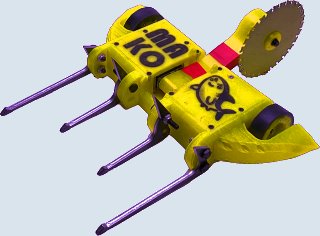

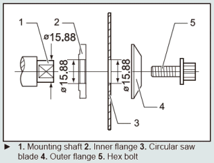
 Comment: Hi. Julian here, the builder of Mako.


 Q: My design for an antweight full body spinner is very tight on space. I don't have room for regular gearmotors, even the little N10 size, and I can't find any right angle gearboxes small enough and fast enough to work.

 Q: What is the usual size of an 'insect sized' arena? [Lagos, Nigeria]
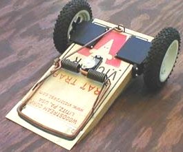


 Q: These weapon performance numbers [at right] from the Run Amok Spinner Weapon Energy Calculator are looking a bit optimistic. I used ChatGPT to calculate the internal resistance of the SunnySky 2450 Kv 2212 motor since they only have the specs up to 1400 Kv version on the site.

 Q: How do robots like Sauron and Vector design their pulleys to fit around the outrunner can? Do they just build it with equal diameter and press fit it on? [Ashburn, Virginia]
 I have been pondering the usefulness of tangential drive for antweight (1 lb) applications, but have concerns regarding its compatibility with foam wheels. In particular, the Repeat Robotics Repeat Tangent motors seem to be effective on the likes of robots like "Super Space Turtle", but I have only seen them used with tires made via custom-molded polyurethane/rubber. Could it be that foam wheels are too "squishy" to create any meaningful contact points with the shaft or simply have a poor friction coefficient (if the latter, could this be mitigated using liquid latex/some other traction coating)? This seemed like a "too good to be true" lightweight 4WD solution. Any feedback is greatly appreciated. [Zanesville, Ohio]
 Q: I'm a new bot builder trying to build an ant for the first time entirely on my own. I'm planning on doing a servo four-bar lifter and I'm planning to use four 30.4mm diameter 14mm wide LEGO tires. I'm curious about what you'd recommend for the drive motors to go with those wheels, given that the robot is a control bot. I've only build heavily aggressive horizontals before so it's a little different.
 A: Mark J. Any specific guidance I might give would depend on design details you have not provided. Beetle, 4WD wedge, Lexan top panel -- are we talking about a BotKits D2? General comments:
 Q: I want to get my D2 beetle running again, but I want to use something stronger than the generic Botkits 22mm gear motors to stay competitive and I can't get the Botkits motors to last on 4S. The Just 'Cuz Dragon 22mm Dartbox Gearmotors look great, but the weird clamp drive motor mounting system the D2 uses won't work with a square Just 'Cuz gearbox.
 Q: 1lb beater bot guy here. I found out that Fingertech sells 2600 kv 2822 motors, which should do nicely for increasing the weapon speed. However, the page for the motor says that the motor draws 24A, and "over double the power output [of the 1100 kv motor] requires a larger ESC." The 40A ESC is a full 6 grams heavier than the 20A ESC, which I also may or may not have already ordered, so I decided to seek a second opinion.

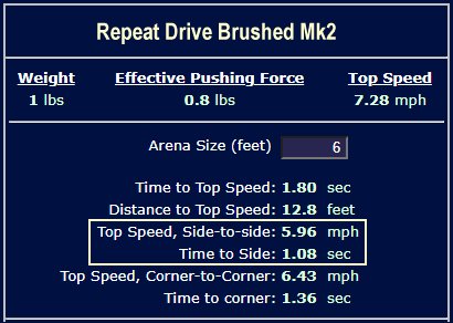
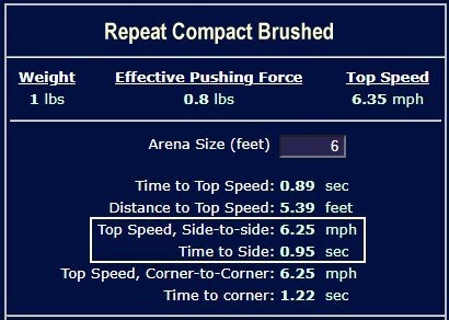
 If the receiver needs a lower voltage, leave the tinyESC leads alone and run the servo power and ground direct to the 7.4 volts:
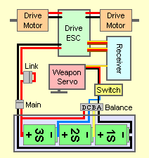 If you still want to use a UBEC, the voltage regulator, battery, and servo are wired in like this, with power and ground (red and black) wires running to the ESCs and the signal wire (white) going to the receiver:
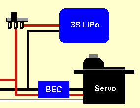
 There are some refinements available, but it's late and it's been a long day.
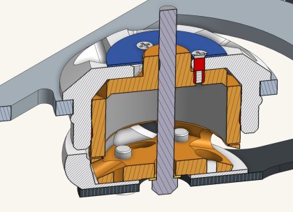 Thanks Alex!
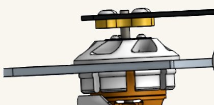 I think that gives a good overview of the weapon hub design.

 1. Let's say my layout uses a two-blade system akin to Droopy's that spins the left blade counterclockwise and the right blade clockwise. Would the body spin clockwise (right) due to the conservation of angular momentum when the left blade is given more power than the right, and the body counterclockwise if the right is given more power? I want to make sure my understanding of the post is correct before continuing.
 Q: What shaft to use for a beetleweight robot? [Indianapolis, Indiana]


 Let's see if I can sort this out for you. In your problem description you refer to "only one output" wire:
 There is a tiny three-position switch near the blue wire attachment to the circuit board. This switch is used to select one of three ESC modes. One of these three modes will give you single-stick "mixed" control of the two motors on CH1 and CH2, but the FlipSky instructions for the switch make no sense:
 Q: It's me, Iceywave. Here to ask an actual question about building a robot!


 Aluminum is in general far too soft to make suitable armor for the current beetleweight level of competition. When they were made eight years ago, both versions of antweight 'Dark Pounder' shown used formed titanium for their bodies, and other 'bots from the team used 'spring steel'. Current wedge material tends toward thick flat panels of abrasion resistant steel. I don't think that "hammered around a tree trunk sheet metal" is a good bet in 2024.


 Second question: I don't know what your previous designs looked like, but if you build the current design I foresee continuing traction problems in your future. You've placed your wheels as far back in the chassis as possible to get chassis clearance in both upright and inverted modes. Doing so leaves a lot of the robot's weight supported by those long forks.
 Q: this was our earlier design, and it had the most abysmal center of gravity possible, which was over the forks, we are currently using 2.25 inch wheels, what do you thing would be the best size option?
 Q: I was desoldering a FingerTech Silver Spark and the little metal tab that I solder to the wire to broke off. I tried adding some solder to the remaining visible metal but its not sticking well. Is there anything I can do to save it or is the motor just screwed?
  A: Mark J. That's how 'Silent Spring' does it: a socket head shoulder bolt with a nylock nut (photos below). Note that you're going to torque this down, so you're going to need a substantial spacer block around the shoulder bolt between the two chassis plates to take the pressure.


 A: Mark J. Thank you, Ryan. Your 'Shock!' weapon design is well thought out with the lower bearing in the weapon disk itself and the upper bearing in the printed pulley. In their question, Redmond spoke of a design with "bearings in a printed hub/pulley attached to the disc" which led to my comment that I wouldn't trust a printed hub holding both bearings. I think you might agree that placing both bearings in the printed pulley/hub would be risky.
 Q: For my horizontal spinner, the motor I want to use is too tall for the robot with the pulley attached as well. There aren't any shorter motors available that can handle the current I need to run, and making the chassis taller would be a waste of weight and harm the rest of the design. I've heard that some robots put the pulley directly on the outside of the brushless outrunner. How would I go about attaching this to, say, a BadAss 2305?
  A: Mark J. The components of a servo mirror the components of a robot drivetrain: a PMDC motor, a gear train, and an electronic speed controller. The servo also has a positional feedback circuit that enables it to attain and hold a specific position.
 Q: Now I did create an antweight of Run Amok however i might have created the wrong kind of antweight what I meant was actually a fairyweight a uk antweight and the rc you send me a link to was convenient and it would be nice to try and find an rc to create a fairyweight version of Run Amok something a little bit shorter not too short for a fairyweight Run Amok scaled R/C per say?
  Q: I'm designing a beetle with a spring powered overhead axe. A spring is cocked and then released, rotating the axe into another robot. I'm going to be using a 21 in-lb torsional spring. I'm aiming for at least 80 joules of energy storage, and according to my calculations that 21 in-lb torsional spring should hold 105 joules:


 First: The drive ESCs are dual-channel units made to independently control two motors with up to five amps of current to each motor. You have both outputs wired together to power a single motor, presumably an attempt to get ten amp capacity from the ESC. This Does Not Work! Each of the two independent channels has its own has its own 'clock driver' to time the output power pulses, so the power pulses will be out of synch with each other. This can cause both control and power consumption issues.

 Many insect-class builders use simple wood screws for this type of connection into soft plastic with good results -- but there are special 'thread forming' screws made with widely spaced and deep threads that are designed to hold in thermoplastics; search for "Plastite" screws. Pick a suitably long screw, drill the correct diameter pilot hole, and sink 'em in.
 If the part will be removed frequently you can cross-drill the chassis and install barrel nuts with machine screws. This type of fastening is commonly used in assemble-it-yourself furniture. They're more work than simple screws and you may have trouble finding small barrel nuts, but the screws will break before they pull thru.
 Although it has fallen a bit out of favor you can certainly use FingerTech Nutstrip. It adds a bit of weight and takes up a little room, but it holds well.
 Q: how do you convert a servos lifting power to a servos crushing power? [Vestal, New York]
 I'm not following your contention that a 'Choo-Choo' linkage has a reach equal to the radius of the driven disk. I make the reach equal to the diameter of the disk plus the length of the "fling" arm attached to said disk (the dark blue arm in the animation). In the animated example the reach is almost three diameters, and the design could be modified to make it more.
 The reach of a slip-geared winch is dependent on the circumference of the pinion gear that drives the spur sector. A small pinion will require a larger portion of its diameter to be 'toothless' in order to provide adequate slip clearance for the spur sector. In the animation, the reach is about 2/3rds the circumference of the pinion.

 Response: P.S. Your response was so quick and cheap that I'm starting to wonder if it's any good
  Q: I'm 3d printing a 1-lb grappler bot. I have a servo that I have been testing with but when I plug it into my receiver it just steals the power from my motors. What am I doing wrong? [Social Media]
 To your questions:
 Shortening Rear Bar [Crank] to 12 mm will prevent the initial 'dip' and allow the spreadsheet to run correctly, but the performance of the system is not very good: there is a very limited range of servo motion combined with a high torque requirement.
 2) The recommended lengths for Front Bar [Rocker]: D are critical for getting best lift height from lifters powering the Rear Bar [Crank] over a full range of motion. Lifters powered by the Front Bar [Rocker] may ignore the recommended Rocker length range, but should note that Rocker motion may be limited by very short Rear Bar [Crank] lengths.
 One last note: You're currently entering measurement values in grams and millimeters so the units for torque are expressed in g-mm. If you enter the lengths as centimeters the torque output will be in the standard g-cm. Yes it's easy to convert, but I suggest staying in standard units to avoid confusion.
 A: Mark J. Since you didn't tell me anything about your current wedge I'm unable to suggest specific improvements. In general, playing the 'lowest wedge' game can be frustrating.
 Q: Hello mark, first I just want to say that this website is
  and I only wish that I had found It sooner!
 Thanks! [Amarillo, or maybe Chicago?]
 Activation of the thwack takes place in the first half a revolution of the drive, so we're interested in torque very low in the RPM range. If we assume that 'throttle response' is a function of torque, we can see from the chart that the Repeat Brushless Drive mirrors the low RPM response of the BotKits gearmotor (presumably their 16MM DC gearmotor). So, a reasonable starting point for your thwack drivetrain might be to input the torque specs of the BotKits gearmotor into the RioBotz design formula. But there's a potential problem...


 If you'd rather swap out your servo I have a couple of low-price options:
 Q: Hello,
 Q: Salutations!
 Q: Hello, it's the builder of Gaston again [see six posts down the page]. I took your advice, and created a completely new design for Gaston. I moved the center of mass closer to the wheels, and switched the motors to these: ServoCity 970 RPM Economy Gear Motor
According to the team tentacle calculator, my 'bot's top speed will now be about 4mph. However, according to the results from the calculator, I don't even need a 0.1 amp hours for a 3 minute match! Did I do something wrong, or are these motors just that powerful? Also, I attached a new rendering of Gaston (don't worry, the wheels and shafts are a work in progress, the body is the main focus). What are your thoughts on the new chassis shape and the motors? Thanks!
Q: Hello, it's the builder of Gaston again [see six posts down the page]. I took your advice, and created a completely new design for Gaston. I moved the center of mass closer to the wheels, and switched the motors to these: ServoCity 970 RPM Economy Gear Motor
According to the team tentacle calculator, my 'bot's top speed will now be about 4mph. However, according to the results from the calculator, I don't even need a 0.1 amp hours for a 3 minute match! Did I do something wrong, or are these motors just that powerful? Also, I attached a new rendering of Gaston (don't worry, the wheels and shafts are a work in progress, the body is the main focus). What are your thoughts on the new chassis shape and the motors? Thanks!
 Everyone knows 1-pounders use those 16mm gear motors (like those from Fingertech) for 2WD systems. Am I able to use four of those motors to make a 4WD system for a 3-pounder, or is it too much weight that could bend the shafts? If this is the case, what would you recommend for a 4WD system that could squeeze into a 3-pound vert?
 1) I'm overweight, and looking to trim some fat around the edges where I can. Currently I have six Shoulder Bolts between two AR500 disks and a TPU pulley, the whole system weighing about 6oz. I had added that many as I was worried about the weapon flexing too much on impact due to the TPU, ultimately warping or bending the weapon. In hindsight however, I could be overengineering a piece I don't have to. Would you recommend removing some of these shoulder bolts?

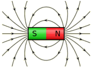 Q: I have an antweight flipper built on a FingerTech Viper chassis. Recently attended my first event, and while the robot survived every match it spent a significant amount of time getting flipped over. This event allowed unlimited magnet downforce. Many events specify a limit on downforce (usually 1 lb for an antweight) and at some point too much downforce over-stresses the drive motors. I am planning to mount magnets on the bottom of the chassis in front of the wheels, but they won't be contacting the arena floor.
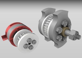 Hello, Mark! I've been working on and off with my ant as of late and have two design-related questions: [Naperville, Illinois]
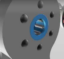 Q2: How would I go about fitting the bearings into the weapon? I don't have access to any fancy or expensive tools and figured it wouldn't be very easy to just press-fit two metal parts together.
 Q: Hi again, this time having a problem with Lipos
 Q: About my recent question concerning chargers, I do have a fingertech, proper lipo charger, which came with the fingertech viper kit, but I don't know how to use it, and also my £3 BBB charged batteries much faster than 90 minutes when it worked. If my fingertech charger isn't suitable either, could you link me with a decent, working one with correct accessories and a video on how to use it?
Many thanks again!
Q: About my recent question concerning chargers, I do have a fingertech, proper lipo charger, which came with the fingertech viper kit, but I don't know how to use it, and also my £3 BBB charged batteries much faster than 90 minutes when it worked. If my fingertech charger isn't suitable either, could you link me with a decent, working one with correct accessories and a video on how to use it?
Many thanks again!
 You'll need to add a switch in the battery line, as covered in the assembly notes on the Bristol Bot Builders website. If the weapon motor spins the wrong direction, reverse any two of the three weapon motor connections to the weapon ESC.
 Q: Hi, Still working on this second antweight and after will definitely move up to a beetle, but still after 4 design revamps am struggling to fit all of my electronics inside my robot - I have looked over multiple designs on the internet but am still having trouble trying to fit everything into a 4' cube - bearing in mind this is a spinner. I was planning to make something not too dissimilar from the pictured robot but was wondering how all of these electronics were fitted in. Probably not a very answerable question but any tips you can give me would be much appreciated.
Thanks! [Oxford, England]
Q: Hi, Still working on this second antweight and after will definitely move up to a beetle, but still after 4 design revamps am struggling to fit all of my electronics inside my robot - I have looked over multiple designs on the internet but am still having trouble trying to fit everything into a 4' cube - bearing in mind this is a spinner. I was planning to make something not too dissimilar from the pictured robot but was wondering how all of these electronics were fitted in. Probably not a very answerable question but any tips you can give me would be much appreciated.
Thanks! [Oxford, England]
 Q: Hello!
 One weakness of the Scorpion Mini is its battery eliminator circuit (BEC). Does the hot chip look like the photo at right, and is it next to the 'BEC' label on the ESC board? That's the voltage regulator that reduces battery voltage to 5 volts to power the ESC and the receiver. Either the voltage regulator has gone bad or your receiver bus is drawing too much power. Take a look at this post in the Ask Aaron Radio and Electronics Archive that covers some of the symptoms that can result from overloading the Scorpion BEC. It sounds like you've cooked the voltage regulator.

 A: Mark J. You're considering two materials with very different properties.
 A: The problem with the tri-blade isn't stability, it's lack of bite. You need to move two of the impactor tips in far enough to make room for a deep impact by the remaining impactor. I only mentioned 'stable' because 'Mini Mulcher' is well known for the serious stability problems it had with an earlier spinner design. See: Polhode Motion for a full explanation.


 Q: "Mounting plates" sold by Fingertech have served me well on ant & beetle motors, is there an equivalently easy solution for fairyweight motors? [Woburn, Massachusetts]
 Q: I stumbled onto some crazy butane jet lighters that are intended for cigars but seem pretty dang impressive. Would it be practical to put one of these in an ant or beetle? [The Aether]
 Q: Hi there. I purchased an Endbots DESC lemon to use in a Beetleweight project, but am finding acquiring a DSM2 transmitter in Europe troublesome. Is it possible to add a different receiver to the project to allow me to use an alternate transmitter? Failing that, are there any other dual channel ESCa that work well for beetles?
 A: Mark J. Did I really say that? A pneumatic system can deliver a great deal more speed and power to a hammer or lifter weapon than a direct-acting electric system -- but they are also a great deal more complex and dangerous. Whether they are 'the way to go' depends on your experience in building combat robots, expertise in metalworking, access to a machine shop, and expectations of performance.
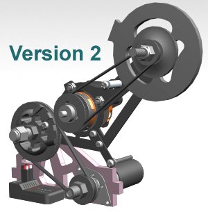 Since the last time I posted my beetleweight has gone from having a hammer to a hammersaw. I had a major issue with the hammer this entire season where the pinion gear thats pressfit onto the hammer motor keeps breaking free of the shaft, killing the hammer.
 Q: Hey Mark, I've taken up the helm of my university's Beetleweight team and we are building a new robot this year. We built one last year but it was a wedgebot and essentially a crash course on how not to build a combat robot: we went way over the weight limit, 3d printed a chassis, and haphazardly threw some silver spark motors in there. Surprisingly enough it ended up working but thankfully I had the foresight to never enter it into a competition.
 Q: I'm building an antweight with a lifter plow, kinda like 'Duck!'. The lifter is powered by twin servos that need to run in opposite directions to work together on the lift, but my transmitter only has elevon mixing and I'm already using that for the drive motors. I have a Y-harness to connect both servos to a single receiver port. Can I re-wire one servo to respond in the opposite direction?
 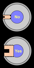 Q: Set screws on my insect-class robot hubs are driving me crazy. They won't hold!!! All I've got is hand tools. Is there anything I can do to make my wheel/gear/pulley hubs more reliable?
  Q: Hey, its me from Anacortes again. I've run into a couple more hitches in the electronics of my beetleweight wedge. A while back you basically had to walk me through how to install the fingertech tinymixer properly, and at the time it seemed to work fine.
 A: Yea, the ESC is toast. All that heat is coming from the charred remains of the former BEC still trying to do something useful and mostly just turning current into heat. Here's what you do:
 Q: Hey its me from Anacortes again. First I want to thank you for diagnosing the BEC problem with my ESC [above]. I never would have figured it out on my own. Anyway, now that I've had some time to reflect on the untimely demise on my ESC, and the fact that I'm way over budget, I'm ready to look for a new ESC. Now, I've seen that some builders seem to be able to save space by using two basic ESCs rather than a single dual ESC. Knowing that I will be running four Kitbots 1000 rpm gearmotors on a 4s lipo, and using a BEC, would you recommend this? [Anacortes, Washington]
 A: Mark J. I don't think you understand how the FingerTech beater bar is used, Jack. Aluminum is used for the 'body' of the beater, but sharp-edged steel machine screws are threaded in as the 'impactors' that acually strike the opponent. The design is popular in part because of the ease with which the impactors can be replaced as they are blunted. It's much cheaper than replacing the whole weapon -- and the sharp edge of your spinner weapon will be blunted quickly.


 Q: Hi it's me from Anacortes again. It has been a week since my first competition with the beetleweight wedge I've been working on. 'Firecracker', as it was called, had its first battle against 'Dark Pummeler', and the short fight ended with my robot in five pieces. This being said, thanks to the kind and encouraging attitude of the other builders, it not a discouraging experience. I've begun a redesign of Firecracker, and along with the new ideas, I have some new questions.
 Q: I've got a 3D printed plastic antweight with a direct-drive drum weapon. The brushless outrunner weapon motor is pressed into the drum. The motor gets so hot after a couple minutes of operation that it melts the plastic and the drum starts to slip out of position. Do I need to put something between the motor and the drum or is there some way to cool the motor? [On-line Forum]
 Q: Okay, so I've noticed that the teeth of the Saifu Antweight kit can be moved around. Normally, the teeth are placed with one side having the teeth in the far left and far right holes, whereas the other side puts the teeth in the middle left and middle right holes (the way I'm describing it makes sense, right?). I was wondering if there would be any advantage against any robots to place all four of the teeth either in the farthest holes or in the center holes. I know that this would fiddle with the way energy is distributed in the drum, but I didn't know if it would be worthwhile, or just an unnecessary thing to play around with.
 Q: This is me again from Anacortes! The Beetleweight wedge I've been building finally has it's electronics! I took your advice and am not going brushless right away, but I have plans to do so in the future. Upon the arrival of the final part, I excitedly botched together a test chassis using some spare 3d printed parts, cardboard, and a lot of hot glue. Everything works after testing using at 2s lipo, but I have run into two problems.


 Mark J. Your question is exactly the type of question we do like to see, Ontario. You've got a problem that has you stumped and it's a problem that other builders might run into as well.

 A: Mark J. 'Good' depends on you design and current requirements.
 Q: Have there ever been any 1-lb robots that used bungee cords to power a spring-loaded weapon (eg axe or flipper)? And were they any good? [Newton Center, Massachusetts]


 The 'speed mod' involves removing one of the four compound gears (the yellow 'Top Hat' gear in the diagram) and mechanically fusing the two gears (red and blue) that share the central gear shaft so that they will spin together as a single compound gear. This eliminates two of the reduction stages, leaving a total reduction of about 16:1 which spins the output shaft 17.5 times as fast.


 Q: I am considering making bottom-mounted wedgelets for my 1lb antweight drumspinner. I would like to know if you have any tips for making and mounting them. [Cleveland, Tennessee]

 Q: What do you think of brush wheels for antweights? Too flimsy? [Syracuse, New York]
 Q: Would an HDPE unibody work for a beetle wedge if it was protected by grade 5 titanium plates? I was hoping the unibody would work as a sort of shock absorber to protect against high energy spinners. [Oak Harbor, Washington]
 Q: So I was thinking to start building an antweight for Massdestruction. I was thinking a overhead grappler (not a crusher) and a wedge. This is gonna be my first combat robot and I'm not even sure she I'm gonna build it. Is this a good one for beginners? Thanks!
  Q: Is there a smaller and lighter ESC solution than a pair of tinyESCs for an insect class bot? I'm having trouble with weight and space on my design. [Saskatchewan, Canada]
 Q: Hi Mark. I have done a design for an antweight (fairyweight in America) motor-in-drum vertical spinner and would welcome any comments you might have. I have done my best to create rounded edges with my mediocre at best CAD skills. [London, England]
 A: Mark J. Yes, lovely rounded edges. It would be very difficult for a vertical spinner to get a good hit on you. I'm worried about vulnerability to horizontal spinners; all of your pretty rounded ramps would deflect a horizontal weapon right up and into waiting vertical hard edges -- Blammo! It's really difficult to be 'round' in all directions.
 A: I like that better. I'm having a bit of trouble with the scale, perhaps because I've never built a UK ant.

 The structure would be:

 The idea is this: A combination of the wider radius of a Bar spinner or Blade combined with the mass of a Drum. Like a squashed Planetoid with thickened equator. Wouldn´t this give more force in the area of impact then in a drum of the same size and mass?

 Q: The German again. I thank you for your honest input and have to reverse the compliments. The design is all based on the info I gathered here and I only can stress the importance of listening and cutting away fancy ideas. I actually design and illustrate common adverts and just love riddles of the real world. But being the offspring of an engineering family I tend to come up with stuff like this. So I will also follow your other rules and cut the spinner out of the first build.
 A: Mark J. Assuming that you have the newer style clamping blade hub as pictured...
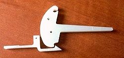
 Q: I am trying to make a spring powered flipper using the same mechanism as 'Dead Air'. The thing is I want to do it in a 150 gram weight class. Do you think this is achievable? [Southampton, England]
 Q: Hi there. Spring flipper guy again. I want my robot to stop reloading when the snail cam reaches the top of the spiral. Is there an easy way to do this?
 Q: I intend to build an underweight beetleweight lifter. The mechanism at the moment is a 4 bar lifter powered by a servomotor. Judging by the T.I. tool, it appears that the front bar 'H' should be driven in a frontbar setup. Is it alright if I attach my servo to the rear bar 'F' though?
[Paris, France]
Q: I intend to build an underweight beetleweight lifter. The mechanism at the moment is a 4 bar lifter powered by a servomotor. Judging by the T.I. tool, it appears that the front bar 'H' should be driven in a frontbar setup. Is it alright if I attach my servo to the rear bar 'F' though?
[Paris, France]
 I'm presently powering it with an E-flite Park 250 motor:
 Q: Hey there sorry if this is a stupid question but I've seen a few US and UK Antweight drum spinners that use there brushless outrunners inside of the drums of spinners on the one side and I'm wondering what they use on other side of the drum to attach it to the chassis/bulkheads as I hope to attempt one myself. Also is there any recommended kind of teeth to use on them e.g screws or possibly something else, Thanks in advance! Ethan [Birmingham, England]
 Q: The description for 'Foiled!' says "Increase effective weight to make wedges useless". What does this mean, and how does it make wedges useless? [Baltimore, Maryland]
 Q: I have built several plastic ants, mostly for fun and for the friends and family to play with (in a safe arena). All of them have direct drive weapons powered by quadcopter motors. The motors specify which direction they are designed to spin based on the threading of the shaft. I never really gave much thought to it at first. I simply turned the power down to about 10 percent, spun the weapon in the direction that the motor was intended to spin, and fun was had by all.
 Rotation on a small diameter shaft can be prevented by using a non-circular shaft (D-shaped, splined, hexagonal, square...) with a matching pattern in the hub. There is nothing to come loose -- the hub simply cannot rotate on the shaft. If the rotor shell of your outrunner motor has some raised pattern at the base of the shaft you can use it as a 'key' to lock into a matching pattern carved into your plastic spinner. The illustration shows a motor with a '+' pattern propeller base that could be used for this purpose.
 Q: If I were to support the motor from both sides (i.e. - have something to support the shaft on the other side) then would you say it's relatively safe? I plan on using the fingertech "chipper" blade.
 A: Mark J. I suspect that the few grams of extra weight on the right side is not responsible for your problem. It's likely a small precision error someplace in the chassis -- not at all uncommon.
 Q: I have a disk for my fairyweight which has two different geometries that I can reverse for different armor types. The disk is 108mm diameter, weighs 35g and is 3mm thick grade 5 titanium. I was wondering if the sharp or flat side would be better for 3d printed armor? [Great Falls, Montana]
 Q: Hello! Guess who? Alright, first things first, I've got a bot still in the works. Should be done soon, hopefully before the end of the year.
 Q: Hey, Mark. I am trying to design a 150g flipper in CAD but I am struggling with component placement. I cannot figure out what is the best material/shape for the flipper part is (currently 1mm thick metal sheet) and where the hinge and snail cam should go. Here is what I have so far: [image at right] [Bristol, England]

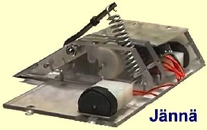 A: Mark J. The 50:1 Pololu motor is unsatisfactory to power your weapon cam: output is much too fast with far too little torque. You need to:
 Q: Hi Mark! A while ago I had asked a question about a beetle crusher, and today I discovered these videos of an ant called Purple Haze: weapon test and fight vs. lifter 'Andrew'. I couldn't figure out how it worked, and I was wondering if you could? [Livonia Mi]

 Q: Hi again, I have a antweight combat robot that has a wedge leading up to a vertical spinner. The wedge is 1mm thick grade 5 titanium, and sits at a 40 degree angle, and screws thread into heat set inserts that are in the 3D printed chassis. The issue is that when I practice driving (with the weapon disconnected) I find that the cap screws are getting in the way of the dummy robot getting fed all the up the wedge. Is there anything I can do? [Great Falls, Montana]


 Your wedge needs to have a lower leading edge than your opponent's wedge if you're going to 'get under' it. That leading edge must lay flat against the arena surface along its entire length, so all sharpening of the edge is done to the underside of the wedge. The final 'hone' of the wedge is done after the wedge is mounted to the robot by placing the 'bot on a flat surface and sliding abrasive paper grit-up back and forth under the wedge to remove any 'low spots'.
 Q: Can you recommend a place where I can get the structural components for my ant? Could I just cut up a plastic cutting board and use that? [Sacramento, CA]

 Q: Do you have any advice for someone who's about to be driven insane by how you have to compress the tires on Fingertech's snap wheels to quark matter densities in order to get the snap ring on? If I spend one more minute with these things I'm going to fall asleep and wake up in Carcosa, if you know what I mean (and you'll know what I mean if you've read The King in Yellow). [North Carolina]
 Q: Because my design requires it, I have to use 4" liteflites for my beetleweight. The issue is that the larger liteflites have a larger inner diameter and are wider than the more common liteflites, so my usual choice of Snap hubs are useless. As I have to make custom hubs anyway, I'm wondering the best way of keeping compression on the hub washer; snap ring or shaft collar? [40 miles north]
 Q: In reply to the Viper kit owner, I've had similar but less pronounced issues with 'Original Robot Do Not Steel', where the robot tends to want to drive in a slightly diagonal line when spinning up. It's probably something to do with the large contact surface between the ground and the blade hub. It's probably something to do with the large contact surface between the ground and the blade hub.


 Q: Well, in that case...
 Q: When did the insect class combat robots first appear? Where was the first insect class tournament? [a question I asked myself, since nobody else had]
 Q: I have a Saifu v2 kit and I want to make it like 'Klazo' from near chaos Robotics with the wedgelets. The wedgelets need to be used to get under 'DDT'. Ok here is the question. Will the wedgelets work? [Ashburn, Virginia]


 Q: Hello Mark. This time I was wondering, what is the easiest way to weigh an insect class robot without having a proper scale?
 A: No. Every component should be individually anchored to the chassis:
 Q: Mark, my old antweight robot has gotten so broken that I have felt that it is beyond repair and I should build a new one. So for my new robot I have gotten a basic chassis drawn up in CAD to try and reuse any parts that I can, but for the weapon, I wanted a spring loaded flipper but the spring compression and release mechanism has been a massive pain for me so just asking if you have any suggestions for designs? [Guangdong, China]
 I'm designing a 3-lb Weaponized 4WD setup. Because of the weapon, to save weight and space, I am looking at making some kind of pulley system for [the drive wheels]. I was wondering how that is typically done? In larger bots I have seen the back wheels powered and the front wheels on dead shafts connected by pulleys. My problem with this set up is that most motors that I am looking at (e.g. 1000 rpm motor) have too short of a shaft for this. Would it be better to have a driven pulley that connects to both wheels on dead shafts or could I alter the gearbox to have a longer shaft?
 Q: Hi
Q: Hi A: Mark J. You're correct to be worried about what happens when a servo takes a sudden impact. An R/C servo is designed to hold the controlled surface firmly against external force -- to the point of breakage. The force of an impact from a beetleweight spinning weapon would be passed along your simple linkage and shatter gears and the housing of the servo. The problem is the 'attaching securely' bit.
 Q: Hi, Mark, I was confused that what is the weight limit in the Beetleweight. I saw the limit is 1.362kg on the FRA forum, but I saw the limit is 1.5 kg on the Kinematic website. What is the weight limit in the Beetleweight? [Guangdong, China]
 A: Mark J. Why do 4-bar questions always come in on weekends when I'm away from the computer that has the 4-bar calculator installed? I can at least give you a starting point...
 A: A blade is easy:
 A: See the diagram at right.

 Q: How do you calculate what servo you need in oz-in as well as speed for this: [upper design at right]
 Take your stainless steel mixing bowls back and get yourself a straight-sided steel cooking pot of suitable size. I'd leave off the angle over the top for the roof mount because spinner shells with a tall 'bracket shape' to their mass can run into stability problems -- see this previous post on spinner instability.
 Angle-sided 'bowl' spinners typically have fairly small impactors mounted along the lower lip of the bowl. They are long enough to allow for several mounting bolts thru the impactor and the lip. 'Sandwiching' the lip between the impactor and a fabricated metal reinforcing strip helps to strengthen the mounting.

 Q: Is there any one good website that shows designs for a bunch of beetle weight robots? I know teams usually have a website but most don't list beetles. [Rockfish, North Carolina]

 Q: How fast should a Motor for an antweight spinner like DDT be? [Baden-wurttemberg, Germany]
 Q: I'm planning to sharpen my ant wedge, and my event organizer (rightfully) requires something to cover any sharp edges to protect blades and builders alike. Whats a good, cheap material that I can quickly take on and off my wedge blade edge that will provide good protection while not dulling my edge?[Charlotte, North Carolina]
 Q: Hey Mark,
 I am looking into building a beetleweight Eggbeater robot. I am trying to find a place to manufacture the actual eggbeater part of the robot. Its 2.5"x3.5"x.625" made out of steel (preferably tool steel). I looked at e-Machine shop to try to manufacture it and their price that they gave me was around $600! That seemed outrageous to me. That's over twice what I am spending on parts for the rest of the robot. I know that robot combat is an expensive hobby, I've built two already, and that the weapon needs to be the sturdiest part of the robot but my question is does this price seem reasonable to you? [location withheld]
 Q: Hey Mark, I am designing my latest ant weight bot to compete at the USATL in May. I want to continue off of the success of Hangar 11. Hangar lost five fights over its carrrier, losing two critical matches to vertical spinners (Altitude and End Game). I want to leverage more clamping ability in my next bot, and I basically want it to be a lifter/clamp bot. This idea came after I won a fight by using the lifter as a clamp bring an opponent to a push out zone. I realized the HXT 12k servo is incredibly powerful and could be effective in both directions. What are the most successful lifter/clamper bots out there? I want to find inspiration. Do you happen to have any suggestions otherwise in terms of design or something?

 A: Depends entirely on your design, New York. In general, torque is WAY more important than degrees of motion.


 Q: Aaron, I have friends coming over from England, and they are young (7,10 ish) and they are into, though have zero experience in, Combat Robotics. I wanted to possibly purchase them Battle Antz from Roaming Robots, but they are out of stock and IMO they are over priced for their quality. However, I like the fact they are small and are beyond RC cars since the have servo lifters, and are very 'cute' in the sense that they seem very put together.
 Response: Wood screws work much better than machine screws in soft plastic, but screws specifically designed for plastic will hold better still and cause less damage to the plastic. I think it's worth the extra effort to find the correct screw. Follow recommendations on correct pilot hole diameter and you'll get excellent results.
 A: I don't think I understand your measurements, Anthony. A steel hole saw 6.375" in diameter with a 0.063" wall thickness but only 0.375" tall? That can't be right! Please clarify.
 Q: Hi Aaron, here is a pic of my Antweight bot so far.

 Q: Aaron, I am trying to design something like a 3lb Juggerbot 3.0 with some slight alterations. I am thinking of using servo with bent arm the will hook into the lifting wedge and act similar to how the Juggerbot 3.0 lifter worked. The point where it connects to the servo allows it to turn. I made the rear end with a flatter edge so I can bolt on a rear guard like 'Pinball'. My concerns are that the servo's drive to the flipper wedge might be able to shift to much and lose power. Thank You.
 Q: Hi Aaron, I was wondering if these parts would work for a antweight pneumatic system
 Q: Based on the photo, do you think my beetleweight will be able to win a match? If so, yay! If not, explain why not. In particular, I am wondering how effective the hammer will be.
 Q: Although it may not flip an antweight 6 inches, the Hitec HS-7940TH Servo has good torque and a blazing fast speed. Could you use this servo to "flip" the other antweight robot? Does the length of the arm change the amount of speed a servo could deliver? Couldn't you use a 4 bar linkage to double the speed, while reducing half of the already large torque rating?
 Q: I have 7.55 oz left for a scoop on my antweight. I want to go with 6AL-4V titanium. How should I mount it, how thick should it be, and how do I bend it? It is for a BattleBots toy.
 Q: How is the beetle 'Cloud of Suspicion' so fast? What does it use for drive?
 Q: I'm getting my beetleweight horizontal spinner's frame waterjetted in a style similar to that of the hobbyweight Fiasco's. Should .0625 Aluminum be sufficient, or will I need something thicker?
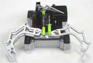 Q: How does the claw mechanism on the antweight 'Grabby' work?
 Q: Did team Inertia Labs build a ICE powered drum antweight?
 Q: What do you think about Inertia Labs' antweight drum spinner 'Hummer' and pneumatic flipper 'Pele'? Do you think it would be good to do something like 'Pele' with the Inertia Labs chassis and flipper kit?
 Q: Were can I get the 'A:1 Complete Antweight Kit' now that Composite Labs shut down?
 A: Servos are way too slow to directly power a flipper. I suppose you could use a servo converted to continuous rotation as a winch to wind a spring for a flipper, but that's too complicated to write about here.
 A: I also mentioned in that post that the winch was too complicated to write about here. I guess you didn't believe me!

