


Privacy Policy

An electric lifter can be an effective 'active' weapon, particularly in 'sportsman' classes that have limitations on spinner weapons. I've edited posts from the Ask Aaron archives into a collection that should answer the most common questions on the design of effective electric lifters.
More detailed information on weapon design can be found in the Robot Weapons archive.
An electric motor-driven lifter must generate enough force to rise the weight of your opponent without stalling or otherwise overloading the motor. A lifter may also be designed to function as a self-righting mechanism to flop your inverted robot back onto its wheels.
- A lifter of modest size and power can be effective in reducing your opponent's pushing force by lifting one or more drive wheels off the arena surface, rendering it easier to push around the arena.
- A more powerful lifter with greater lift height may, when combined with a bit of forward motion, tip over an opponent and reduce its mobility.
- A lifter with the capacity to lift an opponent completely clear of the arena floor might carry it to a pit or boost it over an arena wall.
 Q: How do I calculate the torque needed from a gearmotor to operate a simple beetleweight lifter?
A: The power you'll need from a gearmotor depends on the weightclass and the length of the lifter arm attached to it. For reasonable speed and reliability, select a gearmotor that will stall with about 1.67 times the weightclass on the end of the lifter. Here's the formula to calculate the desired torque:
Q: Is the 1.67 multiplication to provide safety or is the number produced by the equation the actual minimum oz-in?
A: At stall load (maximum torque) the motor has zero speed and the lifter won't actually lift anything -- just barely hold position. Actual lifter speed under load is inversely proportional to the percentage of stall load applied:
Loaded to 90% of stall torque the lifter has 10% of its listed speed;
Loaded to 80% of stall torque the lifter has 20% of its listed speed;
...and so on.
A: A cam lifter slides a pair of thin but wide blades under the opponent then axially twists the blades 90 degrees to lift the 'bot off of its wheels and "high-center" it. The torque required depends on the maximum distance perpendicular to the axis of rotation at which your opponent might be lifted. In the case of a cam lifter that twists the lifter arms rather than levering them upward, you should substitute "Width of the Blade" for "Length of Lifter Arm" to obtain the correct stall torque required from the equation.
A: You're describing a '4-bar mechanism'. The design is widely used in combat lifters, flippers, and some axe/hammer weapons. A search of the Ask Aaron Robot Weapons archive yields more than 100 hits for '4-bar'. There are several advantages:
- A 4-bar linkage can be designed to push forward and up as it extends rather than drawing back and away from the opponent as it rises.
- The extension of the lifter arm can be tailored to keep a fairly constant load on the drive motor as it rises, reducing the motor torque requirement while increasing lift speed.
- The mechanism can be made very compact when retracted, staying away from damage from your opponent's weapons but still able to extend to good height when needed.

Q: Can any of the RS-540 gearmotors be directly mounted to a 12 inch lifting arm for a hobbyweight if the shaft is supported on both sides?
A: The BaneBots P61 132:1 gearbox with an RS-540 gearmotor could be used on a 12" lifting arm for a hobbyweight, if the shaft was well supported. At 12 volts it will provide over 20 pounds of lift force at the end of the arm.
Dissent #1 - You told the guy that asked about a RS540 on a lifter to consider the 132:1 gearbox RS-540 motor. Maybe you should recommend the 64:1 since it has way more than enough torque, or preferably the 45:1, again way more than enough torque.
Counter - I don't agree that the 64:1 and 45:1 gearboxes with an RS-540 motor would provide 'way more than enough torque'. For reliability and maximum lift speed, you want to load the system to no more than 60% of stall torque at maximum lift weight. With a 12" arm and allowing for gearing losses, the RS-540 motor with a 64:1 box stalls at about 10 pounds of lift, and the 45:1 box stalls at less than 8 pounds of lift.
Dissent #2 - All 12 lbs will never be on the lifting appendage at one time. Say a 6" wide bot is on the arm, with one edge at the tip and extending towards the shaft, and in that case it wouldn't be stall torque ÷ 12", it would be stall torque ÷ 6".
Counter - The needed torque is calculated by measuring from the pivot point to the location of the center of mass of the opponent -- not to the closest edge. In your example, the center of mass would be 9" from the pivot. If your arm tip is under the center of mass, you'll need full-weight lift capacity regardless of the width of the opponent.
Having the full weight of the opponent on the end of your lifter is not unusual; the end of the lifting arm can and will lodge in 'bot openings. Large lift torque may also be needed when your opponent is pinned against the arena wall.
 Dissent #3 - No one designs their lifters with that much torque. It's a waste of weight and generally unrealistic. Biohazard is the greatest heavyweight lifter of all time, and it couldn't lift 220 pounds out at the end of its arm.
Counter - Designing for a full-weight lift is entirely realistic. We design our lifters for at least 150% of the weight class they enter. Team Cosmos' very successful hobbyweight 'IO' has a minimum 15 pound lift capacity, and Carlo Bertocchini claims that 'Biohazard' will lift 220 pounds -- the photo at right appears to show it doing just that.
As for being a waste of weight, the BaneBots 132:1 P61 gearbox weighs the same and has the same dimensions as their 64:1 and 45:1 boxes. With the higher gear reduction you get greater lift capacity, less motor stress, lower amperage draw, and faster lift rate at heavy loadings.
A: The usual question is 'How much torque does my lifter need?', but we can back into your question by re-arranging the formula a bit. Here's an example for a featherweight lifter powered by an RS-775 motor:
- Motor Stall Torque: 166 oz-in (BaneBots RS-775 18v @ 18v)
- Gear Reduction Ratio: 64:1 (BaneBots P61)
- Max Torque at Gearbox Output: 166 oz-in × 64 = 10,624 oz-in
- Lifter arm length (pivot to tip): 12 inches
- Lift force at end of lifter arm @ motor stall: 10,624 oz-in ÷ 12 inches = 885 ounces = 55.3 pounds
- Increasing motor stall torque increases lift force -- decreasing motor stall torque decreases lift force.
- Increasing the gearbox reduction increases lift force -- decreasing the gearbox reduction decreases lift force.
- Increasing the lifter arm length decreases lift force -- decreasing the lifter arm length increases lift force.
Robot haiku:
|
For good lifter speed, Aim for twice the motor torque The calcs say you need. |
Q: I'm working on a design for an antweight (US) lifter and was running the calculations using a Silverspark motor to power the weapon. Here's what I have:
Maximum Lifting Weight: 32 ounces
Maximum Torque at Gearbox (oz-in):
Motor Stall Torque: 0.64 oz-in (Fingertech Silverspark @ 6v)
Torque Overage Factor: 2
Gear Ratio Required: ((128 ÷ 0.64) × 2) = 400:1
A: Your math is fine, although I note that you're using a two-pound lift weight and a two-times torque overage factor, which means the lifter could provide four-pounds of lift before stalling. That's a little bit overkill. I usually recommend a total available lift force of 1.67 times the weight class, which would make your ratio calculation:
Q: I plan on running the Siverspark motor at 12v - 14v rather than their rated 6 volts. Does this affect the stall torque, or does it remain constant regardless of the voltage applied to the motors?
A: Stall torque, stall current, and no-load RPM of a PMDC motor increase proportionally with voltage. Bumping up the voltage from 6 volts to 12 volts will double the stall torque of the motor, so your new calculation will be:
 Q: Does the lifter have to be a straight bar for the math to work? My idea involves something similar to the one 'Nyx' uses [pictured at right].
A: The math works for any single-pivot lifting arm. Measure the arm length as a straight line from center of axle to farthest tip of the arm. Fancy bends and angles along the way don't count.
Pay attention to the very large gears 'Nyx' uses to handle the large torque loads on its long lift arm. A small BaneBots gearbox used as the pivot is unlikely to survive the huge torque loads seen in this design.
Q: Can I use a Banebots gearbox, then use external gears and/or chains to achieve the right ratio? I assume that's how 'Nyx' works.
A: Yes. That will reduce the torque load on the BaneBots gearbox. Chains require less precise positioning than gears and are more forgiving of minor misalignment.
Q: When I tried to install the T.i. 4-bar simulator on my computer I got an error message the simulator requires ".NET Framework 1.1". I found the free .NET Framework download on the Microsoft website, but it won't install on my Windows 8.1 computer. Will any of the later versions of .NET Framework work with the T.i. simulator?
![]() A: The T.i. 4-bar simulator written by Adam Wrigley of T.i. Combat Robotics is written in a version of Visual Basic that is no longer supported by Microsoft and is quite difficult to get running on current versions of Windows. Until recently I kept a 'retired' desktop in my basement running 'Windows XP' just to run the simulator!
A: The T.i. 4-bar simulator written by Adam Wrigley of T.i. Combat Robotics is written in a version of Visual Basic that is no longer supported by Microsoft and is quite difficult to get running on current versions of Windows. Until recently I kept a 'retired' desktop in my basement running 'Windows XP' just to run the simulator!
The recommended fix is to download and run the Team Run Amok 4-Bar Lifter Spreadsheet discussed in the post above. It offers the same capabilities as the T.i. simulator and will run in any version of Microsoft Excel from the last 20 years or so.
Q: I've tried unsuccessfully to master 4-bar but cannot get a successful layout no matter what input values I use. For a beetle, what would some of the approximate dimension be? My overall robot dimensions are currently 10" x 6" x 2.25".
 A: I can at least give you a starting point. Team Run Amok's beetleweight 4-bar lifter 'Zpatula' has a front bar powered mechanism with these dimensions:
|
Q: I'm designing a 4-bar lifter powered by a servomotor. Judging by the T.I. tool, it appears that the front bar 'H' should be driven in a frontbar setup. Would it be alright if I attach my servo to the rear bar 'F'?
A: I understand your confusion.
Early versions of the T.i. Four-Bar Simulator were only capable of modeling lifter designs with powered front bars, and the diagrams all showed lifters with that layout. From version 2.0.6 onward the tool could model either front or rear powered bars, but the diagrams were not updated.
You may power either the front or rear bar, but in most cases it is preferable to power the shorter of the two 'upright' bars as that approach requires less torque. Click the 'Change to Rear Bar' button on the simulator screen to switch the calculations to a powered rear bar.
Q: I plan to build a 4 bar lifter. If I power it with two linear actuators each with 150lb force, do I get 300lb of lifting power out of them?
A: You get 300 pounds of actuation force, but that doesn't mean that your lifter has a 300 pound lift capacity:
- Two 150 pound force actuators give you a maximum 300 pounds of force input to the 4-bar system (at stall).
- The actual output force of the 4-bar lifter will vary with the attachment point of the actuators and the geometry of the 4-bar mechanism. The actuators for the 4-bar lifter of heavyweight 'BioHazard' provide more than 2,800 pounds of force to lift a 220 pound opponent. You will benefit from reading the BioHazard Mechanical Design page.
- Actuators slow down as the load on them increases. An actuator that has a speed of 4 inches per second and a 100 pound force rating will slow to half that speed when loaded with 50 pounds, a quarter of that speed at 75 pounds, and will come to a full stop at 100 pounds of load.
Q: What's the difference between a 3-bar and a 4-bar mechanism?
A: Absolutely nothing.

 Q: I was planning on using a 182:1 gearbox and a Banebots 775 motor for a featherweight lifter, but I'm torn between two designs. One is inspired by 'DUCK!' with a short, beefy lifter on the front. The other is based on UK heavyweight 'Shockwave' with a lifter that can rotate 360 degrees around itself. I'd assume that one version is better at doing something than the other, I just don't happen to know what that is.
- What are the pros and cons of each design?
- What problems might be encountered with each weapon design?
A: How did you decide on a 182:1 gear ratio for your lifter before you settled on a lifter design? The gear ratio determines the torque available to the lifter, and the torque required for a simple lever-arm lifter depends on the length of the arm from axle to tip. Examples:
-
A featherweight lifter with a one-foot lifter arm will require torque equal to
1 foot × 30 pounds = 30 foot-poundsto offset the weight of a featherweight opponent and start to lift it. I recommend gearing for twice that level of torque to allow the lifter motor to quickly lift that amount of weight: 60 foot-pounds of torque. A 12 volt BaneBots 775 motor delivers 61 ounce-inches of stall torque at its rated voltage; 61 in-oz = 0.18 ft-lb. That makes the required gear reduction:(1 foot × 60 pounds) ÷ 0.18 foot-pounds = 333:1
- Shortening the lifter arm length to half-a-foot reduces the torque requirement and required gear reduction by half: 30 foot-pounds, achievable with a 167:1 ratio gearbox.
- Shortening the lifter arm farther to a 'Feather Duck!' range quarter-foot reduces the torque requirement and required gear reduction by a factor of four: 15 foot-pounds with an 83:1 ratio gearbox. Maybe even less because such a short lifter can really only hope to lift one end of your opponent.
Pros and Cons
- A 'Shockwave' style long-arm lifter can lift your opponent higher and can also self-right your 'bot. The long lifter arms require more torque to operate, and because the long arms act as levers they can transmit greater shock from a spinner hit back to the gearbox.
- A 'Duck!" style short-arm lifter can really only lift one end of your opponent off the floor and break their traction to make them easier to push. The short lifter arms are by nature stronger, require much less torque to be effective, and will transmit less spinner shock to the gearbox. If you're building a 'brick', this is your preferred approach.
Q: I noticed that 'Sandstorm' uses two individual gearboxes connected jointly to power its lifter. Is this in any way more effective than using one gearbox with more power? If so, why?
 A: Warning: Don't confuse 'power' and 'torque'. Mechanical 'power' is expressed as rotational force (torque) multiplied by its rotational speed (RPM). A reduction gearbox will increase output torque, but will also decrease speed in equal measure -- there is no net increase in 'power' regardless of the gear ratio.
Why use two gearboxes/motors rather than one gearbox with a motor twice as powerful? Electric lifter weapons require a great deal of torque, but there is a limit to how much torque a given gearbox can handle without destroying itself. BaneBots gives this warning for their P80 gearboxes in all ratios:
We recommend maximum torque not exceed 85 ft-lb for all P80 Series Gearboxes. It is possible to mount motors that will exceed this in higher gear reductions. Higher reduction gearboxes should be utilized primarily for speed reduction. Designs utilizing a P60 gearbox and motor combination that will exceed 85 ft-lb should include a method of limiting torque to prevent damage to the gearbox.
 Q: Is there a way for a featherweight lifter to be actuated by a motor with gear and chain without any sprocket hanging out of the bot and without having it be a 4 bar lifter?
I'd like to make a long rear-hinged design -- not all 'up front' like 'Sewer Snake', more like 'Dantomkia' but not gas operated.
A: A long-armed rear-hinged featherweight lifter requires enormous torque to lift an opponent out at the far end of the arm. A short-armed featherweight lifter like 'Nyx' (pictured) can get away with a small sprocket on the lifter axle, but each time the length of the lifter arm doubles the torque required to operate the lifter also doubles. By the time the arm reaches all the way back to the rear of the robot the torque needed raises to gearbox-shattering levels unless a big chain sprocket is used on the lifter axle.
You can run the torque calculations to see for yourself how much torque is needed and shop around for a gearbox that can survive the load and provide the needed reduction ratio -- but you'll find that a suitable unit is heavy, bulky, and expensive. Four-bar mechanisms are popular for electric lifters because the torque requirement for a long lifter arm is greatly reduced. Perhaps you should reconsider your design?
Q: Rather than having a huge plow that can lift up and down, what if I used a small lifting arm in-between two hinged wedges? Any advantages and disadvantages to having a small lifter like that rather than a wide plow?
A: Some random lifter observations:
- A narrow lifter arm as you describe can let an opponent 'fall off' to one side or the other. It's kinda like trying to eat peas with the flat side of a knife, except the peas have wheels and they're trying to drive off the knife.
- You can get away with a narrow arm on a 4-bar lifter that is moving upward and toward your opponent (think 'BioHazard') but the combination of a short and narrow arm with a single pivot lifter that is pulling away from your opponent has a very limited number of real-life circumstances where it might be useful.
- A wide plow lifter has the added advantage of 'getting out of its own way' as it rises, allowing your 'bot to move forward and keep the lifter under the edge of your opponent rather than pulling the lifter away. If either of the hinged wedges in your design is not 'under' your opponent, they will block and push them off the lifter as it rises. Bah!
Q: I'm thinking of adding a 1:1 gear or chain system connecting the lifter to the gearmotor as a simple way to alleviate shock from direct hits on the lifter. Would something like this work? If not, how can I reduce the shock felt on the lifting arm, especially during a heavy collision with a spinner?
A: Inserting a 1:1 gear or chain system connecting the gearbox to the lifter will not significantly reduce shock loading on the gearbox -- shock on the lifter will be passed on at a 1:1 ratio the box. You will often see additional gear reduction between a lifter and a gearbox, and that DOES reduce shock transmission! An external 4:1 reduction will increase the torque from the gearbox to the lifter by a factor of four, and will reduce the torque of shock transmitted back along the lifter toward the gearbox by the same factor.
It's also fairly common to insert a v-belt drive from the gearmotor to the lifter. The v-belt can be adjusted to 'slip' as the torque approaches levels that might endanger the gearbox.
 Q: I am looking at building a 30 pound robot this year, and had a question for the lifter which will be around a foot long.
I was looking at using a BaneBots P61 gearbox for the lifter, but they say to not expose the gearbox to more than 45 ft-lbs of torque. I'll add a chain drive between the gearbox and lifter to get the torque loading down when lifting 30 pounds, but if I run into the wall or the other robot or a weapon with the arm, how do I keep the gearbox from breaking on the impact when all that force goes back into it?
A: Plug 'torque limiter' into your favorite search engine. There are a wide range of industrial devices that will limit torque to the range you seek. If you want to keep it simple (and cheap) a V-belt and pulley system in place of your proposed chain/sprocket can be set to slip as the torque approaches your 45 ft-lb limit.
Alternately, consider a lifter design similar that used in heavyweight 'Polar Vortex'. Their lifter mechanism presses down against the arena floor and is isolated from impact forces acting on the wedge.
Q: How can you self right using a 4-bar lifter? I saw this video on youtube but I just can't figure it out.
A: The video of antweight 'Pad Thai Doodle Ninja' self-righting is taken from an awful angle to actually see what's happening. I think you'll get a much better idea of the process by watching this video of 'BioHazard' self-righting. Getting a 4-bar lifter to flop back upright requires extensive pre-planning and a fair amount of tinkering. You'll notice small extension 'claws' on the back of Pad Tai's lifter that I'm sure were added to get the self-righting to work.
Charles Guan's 'Equals Zero' website has an archive for Pad Thai that includes the design requirements for getting a 4-bar to self-right:
 "[Self-righting] is kind of tricky with 4-bar lifters. You really have to take into account the center of gravity of the bot, and the length and extension of the arm, in order to facilitate this. Generally, 4-bar lifter bots flop onto their backs and come to rest on the arm whenever it is then deployed, as the CG is too far forward, and no self-righting is possible. [The classic video of former Battlebots heavyweight Biohazard shows how a 4-bar can self right.]
Notice how [BioHazard's] center of gravity is far enough back that the bot hinges on its rear edge and does not come to rest on the arm. The arm's retraction then keeps the CG within the line drawn between the arm's contact point and the bot's rear edge, and it gathers enough momentum to push back over. Making it able to do this meant making the arm extend all the way back across the bot. Notice also how Biohazard had a 'tang' at the very back of the arm, a part that sticks up - this aids in the maneuver by making the contact point with the ground further forward, so the 'line' is longer.
This goal meant that I was continually watching the bot's center of gravity in autodesk Inventor, and also continually modifying the linkage to suit. The arm had to have a certain amount of extension to make sure the CG was in the right place, and that extension had to jive with everything else's placement."
Strong end stops and a 'servo saver' on the servo output shaft are mandatory.
Q: I have a question on behavior of servo lifters in the insect weight classes. I don't really understand the internal workings of a servo. If my lifter wedge is attached directly to a servo and it gets hit by a vertical spinner will it:
- Flip upward like it was freely hinged?
- Remain fixed like it was just a solid piece in the front?
- Act in some way in-between?
 A: You're correct to be worried about what happens when a servo linkage takes a sudden impact. An R/C servo is designed to hold the controlled surface firmly against external force -- even to the point of breakage. The force of an impact from a spinning weapon can certainly be passed along a simple linkage to shatter gears and the housing of the servo.
A four-bar mechanism offers advantages over direct attachment to the servo. Aside from the ability of the arm to curve forward and away as it lifts, the four-bar structure itself can direct some of the force of an impact away from the delicate servo and into the more robust hinges attached to the chassis. However, the servo itself is still vulnerable because of its unyielding geartrain. R/C car racers have a similar problem when their front wheels run into unyielding objects. They use a device called a 'servo saver' that replaces the standard servo output disc/bar on their steering servo to absorb shock loads. A servo saver contains a spring mechanism that allows a certain amount of 'give' that lessens an abrupt impact and transmits less of the force on to the delicate servo geartrain. Run a web search for 'servo saver' to find several different designs. Evaluate those designs to see how well each might fit into your lifter concept. |
Q: How do you convert a servo's lifting power to a servo's crushing power?
A: Hobby servos do not come with a rated 'lifting power'. The specs they come with are:
- Speed: The time needed to traverse 60 degrees of rotation under no load; and
- Stall Torque: The maximum (stall) torque the servo can produce.
- Speed: 0.11 sec (at no load)
- Stall torque: 35 kg-cm
Note that servos don't like to spend a lot of time stalled at full load. They don't live long under these conditions.
 Q: I'm 3d printing a 1-lb grappler bot. I have a servo that I have been testing with but when I plug it into my receiver it just steals the power from my motors. What am I doing wrong? [Social Media]
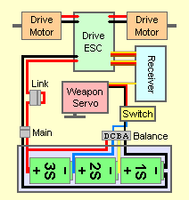
A: A servo can draw quite a bit of current -- often more current than the small battery eliminator circuit (BEC) in the drive motor ESC can provide. If your receiver is powered simply by plugging your ESC into it that's likely your problem. When your servo motor moves it draws current, the BEC can't provide enough current, and the voltage drops below what the receiver needs to control your robot correctly. You'll need a separate high-current BEC to power your servo: something like this.
As shown in the diagram, you'll need to snip away the center red wire in the three-wire cables from your ESCs to the receiver. This prevents the ESC and the new stand-alone BEC from both trying to power the receiver.
Q: I am making an antweight with a lifter. I know there are a lot of variables, but can you give any general recommendations on specific servos?
A: Very generally -- you need speed, torque, and metal gears. A few options:

Note that all of these servos pull several amps of current -- way too much to run them from the Battery Eliminator Circuit in your speed controller, and their best performance requires voltage too high for most receivers. Follow the circuit diagram to run the servo from a battery with a higher voltage than the receiver.
Q: I'm running a 3S lipo pack in my antweight lifter. I've blown up two lifter servos wiring them straight to the battery [see diagram in post above]. I don't have weight allowance or space for a high current BEC. Is there anything I can do to keep my servo healthy?
A: Battery Tap You can tap into the balance connector on your 3S LiPo to feed 7.4 volts direct to your servo while still supplying 11.1 volts to your motors. The amount of current used by a servo is small relative to the drive motors -- just balance charge the LiPos every time to keep the cells happy.
Q: How are typical insect class 4-bar servo lifters built?
A: There are many links, diagrams, and photos for insect-class servo lifters in the Ants, Beetles, and Fairies archive.
Q: I was hoping I could get some feedback on my antweight. I'm trying to clean up this design a little. It has a reverse lifter like 'Firestorm' that uses nutstrip attached to a servo to push the plastic lifter forward. That works for the most part but it doesn’t go forward enough to self right. Also the nutstrip sticks out the back of the wedge, making it susceptible to snagging.
I was wondering if you had a way to fix these two design problems?


A: You have enough 'nutstrip' there to re-arrange into a compact '4-Bar' mechanism that will solve both of your issues. See the diagram below. Play with the lengths of the blue and green bars and the hinged attachment point of the blue bar to your lifter until you get enough extension to 'self-right'. It should all tuck neatly within the length of your 'bot.

 Q: How do you calculate servo torque needed for the servo powered lifter design in the drawing?
I have the T.i. Combat Robotics 4-Bar Simulator but it keeps giving me error messages with this design. I have an HS-5585 servo that I'd like to use for a beetleweight. A: The design diagrammed is Team Run Amok's inverted 4-bar servo lifter. It's a compact and robust design, but the T.i Simulator can't model this layout. A conventional 4-bar used in a lifter has the powered link pushing the 'G' bar forward to raise the mechanism. This design has the 'G' bar stationary and the powered link pushing the 'E' bar forward. That's backward logic to the calculator and it balks. Fortunately, I had this layout in mind when I was writing the new Team Run Amok 4-Bar Lifter Spreadsheet. There is a second version of the spreadsheet called the 'Team Run Amok Servo Lifter Spreadsheet' specifically written for the type of 'inverted' linkage you're referencing. You may download either version from the given link. |
 Q: In the servo lifter diagram, is the point where the blue part connects with the servo a hinge? If so, how do I construct this?
A: All of the 'dot in a circle' connections in the diagram are pivot hinges. Your local hobby shop will have a variety of pivot fasteners to fit servo horns. Websearch: 'servo horn connector'.
Q: Hey Aaron,
I am getting a lot of different results and variations of servo horn connectors when I Google them. Do you know any specific ones/could you find any? I don't mean for you to be my search monkey but I am not exactly certain which variation would be beneficial.
A: The simplest and strongest connectors are probably the Z-bend and L-bend styles. Suggest you read this guide.
 Q: I am decent with math and I have the Total Insanity 4-bar simulator program, but I do not fully understand the program and I do not know how much my arm is going to weigh. I took apart one a Biohazard Pro R/C toy and measured the length of the arms (in the diagram it would be the red bar and the bar that is replaced with the servo) and I saw that it was 2.5" and 4". Would that be effective to scale that down to my antweight? I understand that it's easy to mess up a four bar lifter. Any thoughts on what the best solution could be?
A: I can clear up one of your problems quickly -- the weight of your lifter arm is NOT one of the inputs to the simulator. The input is the weight the mechanism must lift out on the end of your lifter arm. For an antweight that should most likely be one pound.
A 4-bar lifter mechanism can provide a very wide range of output motions from a given input. All the bar lengths and pivot heights are important to the performance of the mechanism, not just the two bars you measured. There is no easy to define 'best solution'. You have to play with the bar lengths until you get a suitable lifting motion, lift strength, and reasonable servo loading. Spend some time with the simulator and get the hang of it. If you come up with a deisgn you think might work, I can check your work for you.
A: You need more than lifting force to have an electric flipper; you also need speed. Twenty times your opponent's weight in lift won't get them airborne if applied slowly. Torque times speed equals power, and you really aren't going to get enough power from a suitably sized electric motor -- unless you have a way to store that power and release it in an explosive burst. Maybe if you used an electric motor to wind-up a spring...
Take a look at the Ask Aaron Spring Flipper Design page.
Q: For my first robot, I was thinking of building a finger tech robotics kit and adding a lifter like Whiplash's without the spinner. Any good?
A: The major flaw with your 'lifter idea' is that you are a first-time builder. FAQ #8 refers you to this list of reasons why a first-time builder should not build a 'bot with an active weapon. That's my honest answer. If you'd rather have "The answer the guy asking the question wants to hear" just click this button:


Copyright 2019 by Mark Joerger -- all rights reserved.