This page is one of several archives of 'Ask Aaron' questions and answers categorized by topic. To see the most recent questions or to ask a new question, go to the Ask Aaron Home Page.
Take a tour of posts in this Ask Aaron Archive that have been referenced to answer new questions. Click the 'Mystery Post Tour' button above to get started.
Date marker: January 2026
Needs a Mixer Fixer
Q: I've been driving my robot around my test box and notice that the robot is turning in the opposite direction as my controller inputs. Any ideas why? [Sacramento-ish]
A: Mark J. Yes -- your ESC channels are plugged into the wrong receiver ports. If you are using channels 1 and 2, unplug the receiver connectors and plug the connector that was in channel 1 into channel 2 and vice versa.
Alternately, you can use the 'Channel Reverse' function on your transmitter to reverse the response of your steering channel (most likely Channel 1 - Aileron). You didn't mention which transmitter you have, but most have this feature. This is handy if you have an "all-in-one" receiver/DESC with no channel plugs (like a Malenki).
I spent a good deal of time creating the Team Run Amok Combat Robot Mixer Fixer -- answer three questions about your robot and it will give you a complete and accurate solution to your mixing problems. Give it a try next time.
Consult the FAQ
Q: what configuration should my electronics be in ? Its a scorpion nano, but i don't know how i am supposed to attach a weapon motor and esc. if i need to get/include anything else please tell me. [Atlanta, Georgia]
A: Mark J. See Frequently Asked Questions #19 for a complete, annotated diagram -- and read the rest of the FAQ while you're there.
Q: sorry, i had a photo attached
A:
Yes, you attached a photo of your weapon ESC. It is an entirely standard brushless weapon motor ESC -- exactly as shown in the FAQ #19 diagram. I chose not to reprint the image here.
Q: also this is my esc [photo attached]
A: Yes, that is a Scorpion Nano. It wires up just as shown in the FAQ #19 diagram. A few specific comments based on your photo:
It may be convenient for you to purchase a set of the
Mini 4-position Terminal Blocks to connect your Nano and weapon ESCs to the leads from the JST connector -- as mentioned in the ItGresa instructions.
Your weapon ESC and weapon motor lack the connectors needed to splice them together. A set of "bullet connectors" will do that job.
Inside the Faraday Cage
Q: A question about antenna in a metal box. I've read here that it is best to put it outside the metal box or at least use radio transparent materials, but how do the heavyweights in battlebots still manage to receive signals? Does poking a hole help? [Central Luzon, Philippines]
A: Mark J. A continuous box of conductive plate or mesh forms a Faraday Cage that can block radio reception -- but most heavyweight robots have substantial gaps for weaponry or feature non-conductive cover plates. Very small holes are not effective at allowing radio signals to enter but gaps of 1/2" or more will allow a 2.4 GHz frequency wave to leak in.
It's also vitally important to position the receiver and antennae away from internal components that produce electrical interference. This comment from Team Monsoon at their Reddit AMA highlights that problem:
"We've never really had any major issues with this version of Monsoon, however when we first went through safety at BattleBots the robot wouldn't drive straight and we had very poor radio signal. The receiver aerials were routed underneath our motor phase cables and creating interference. After a bit of wire re-arranging it was totally fine."
Q: I want to set up my Radiomaster Zorro for arcade stick style driving (throttle controls forward/back and steering is on the aileron). I have done single stick mixing before on a Flysky but I am still trying to learn the Zorro. I think I understand the steps in your EdgeTX Combat Radio Tutorial to set up a single-stick mix, but what would I need to change to make it dual-stick? [Somewhere in California]
A: Mark J. My new combat robot setup guide for EdgeTX uses a Radiomaster Zorro transmitter for its example. This Link will jump you straight into the single stick mixing section of the guide.
This is what the Mixes Screen looks like with a right single-stick mix using CH1 Aileron and CH2 Elevator:
To shift forward/reverse control to the left stick we will remove CH2 Elevator from the mix and add CH3 Throttle in its place:
You'll also need to adjust your left gimbal to be self-centering. Here's a video: Zorro gimbal adjustment.
Once you get the mix set on your transmitter it may still need to be tweaked if the robot is not responding correctly. Maybe a forward command causes the robot to turn left? My Combat Robot Mixer Fixer will ask three questions about your robot and will provide a quick correction.
It Keeps Blinking
Q: I have been trying to pair my FlySky FS-i6 transmitter with a new FS2A receiver but am having difficulties. The FS2A has never been paired before and the FS-i6 has only been paired with the FS-iA6B receiver it came with (successfully).
The issue I have is when I put the receiver into pairing mode (fast blinking) and turn on the transmitter in pairing mode, the receiver immediately exits pairing mode and begins blinking slowly again -- it doesn't switch to a solid light to indicate pairing like the FS-iA6B did.
Do you have any idea why this happens or how to fix it? [Boardman, Oregon]
A: Mark J. Your FS2A receiver is binding correctly, but its LED display is a little different than the FS-iA6B you previously bound.
When the FS2A in bind mode (rapid flashing) recognizes the FS-i6 transmitter in bind mode it will bind and revert to slow flashing -- exactly what you are seeing. Turn off the transmitter and power-down the receiver. When you power back up (transmitter then receiver) the FS2A will correctly display "solid on" indicating that it is bound to your transmitter.
And a Lot More
Q: Can a xt60 connecter handle 30 volts. [Glassboro, New Jersey]
A: Mark J. XT-60 electrical connectors are rated for a maximum 500 volts DC at up to 60 continuous amps. For the short periods seen in robot combat matches they survive 120 amp peak current nicely.
Dirty Receiver Power
Note: This post had a couple of false starts. I've edited it down to where the hamburger got good.
Q: My robot is a beetleweight with an unusually high current draw from the weapon, and I have switched from a Neutron ESC to the Iflight Blitz E80 (the Neutrons kept dying), but now there are issues with drive sides turning off in the middle of a fight, with the robot losing connection for a few seconds, and with the ER4 receivers going bad.
I had been powering the receiver from the BEC on the Repeat Dual ESC but I've been experimenting with using the balance lead of my 6S LIHV battery to power the receiver with a 2S voltage, and I am currently using wires 1 and 3 (marked with an A). Could I switch to using two wires in the middle, such as the ones marked with a B?
I had hoped to have the problems fixed by now, but the next event is NHRL and I can't reliably replicate any of these issues at home to test possible solutions. I am trying to add as many layers of protection as possible to try to fix the possible causes of the issues, such as:
Drawing receiver power from center wires on the balance lead to reduce voltage spikes (not sure if it would actually do that)
Separate (bigger) BEC to reduce chances of voltage spikes to the receiver, and to make sure it can keep up with the current demand during voltage sag
Ferrite rings around all wires from the weapon ESC to reduce voltage ripples to the receiver and Dual ESC
Adjusting capacitor sizes (on the receiver, weapon ESC, and drive ESC)
My main question is: Would powering the receiver from the balance lead reduce voltage spikes and voltage sag since the positive wire is now separated by multiple cells from the main power wire?
I'm trying to do everything possible to solve these issues now since I don't have any more chances to test changes individually. [Raleigh, North Carolina]
A: Mark J. That must be a HUGE current draw To cause such trouble.
About your port tap: The balance port tap you propose creates a "floating ground" within the wiring circuit. The receiver ground is now at a higher voltage potential than the ground used by the ESCs. If you include the ground lead from the receiver to the ESC there will be a dead short across the first two cells of your battery -- a condition known as a "ground loop". See this archived post for a more complete discussion of ground loops.
Going with only a signal wire from the receiver to the ESC prevents the ground loop -- but the ESCs expect to see a receiver signal that ranges from about ~6 volts (high) to 0 volts (low) compared to the ESC ground. If the receiver is setting on a circuit with a ground three cells above the ESC ground, the ESCs are going to see a signal ranging from about 18 volts (high) to 12 volts (low). ESCs aren't likely to respond well to that signal.
The general rule is: "Wire Everything to a Common Ground."
To your main question: Pulling power from the center cells of the battery will not offer significant protection from voltage fluctuation. Current is drawn equally across all cells in the battery and any voltage fluctuations will effect all cells equally as well. Even if you could avoid the ground loop and signal voltage problems the tactic will not solve your voltage issues.
Hard core R/C airplane guys often use a voltage stabilizer on their receivers that "helps to eliminate brownouts and prevents your receiver from rebooting." It's just a good sized electrolytic capacitor that plugs into an unused receiver port to offer a little buffering. But it sounds like the voltage fluctuations you're seeing are way too large to be solved by a capacitor, ferrite rings, or a larger BEC.
You've run out of time for experimentation and you need something absolutely guaranteed to eliminate receiver power fluctuations: stop trying to clean up your existing receiver power source and simply replace it. Your ER4 receiver is happy with anything from 4.5 to 8.4 volts input, so add a dedicated 2S 150mAh LiPo to power the receiver directly. Weight is only about 10 grams and a full charge is good for well better than an hour of operation. You will likely want to include a ground wire from one receiver port to one of the ESCs to provide a reliable signal return path.
What's Left?
Q: Build: Repeat Robotics 16mm Brushed Planetary Motors MK2 and a Scorpion Nano 2.1 brushed ESC. When starting moving one motor stops. After a restart, the motor works again. I've switched out the Scorpion Nano, the motor, and the fully charged 3S battery. The issue remains.
Looking for some problem solving tips. [Social Media]
A: Mark J. OK -- it isn't the motor, it isn't the ESC, and it isn't the battery. Tell me about your radio system.
Comment: Ooo, good call. I'll switch to another Rx and Tx.
Wired Remotes Rule
Q: Wired remote control different structure [Maharashtra, Bharat]
A: Mark J. Sure. Try this:
More Reduction Please
Q: Hello, I am trying to build a 30Lb combat robot and I am dipping into some new electronics I haven't used before. For my drive I have 2, Andymark 775 redlines, geared down by a ratio of 10. I am using 2 Vex Talon SRX ESCs for both motors. For the weapon system I am using a Castle 2028 800Kv brushless motor, with a Mamba monster X esc. My batteries are Powerhobby 4S 15.2V 4200mah 120C GRAPHENE + HV Lipo Battery.
I want to run these batteries in series to provide 8S for the weapons system, while allowing the drive motors to run off each individual battery at 4S. The talons can handle 4S but the redlines are 12V motors. So I'll just change the rate through my drone controller to output less voltage. The castle weapon system is kind of what I'm new at. I have never used it before and I don't want to fry anything with the power system I am trying to implement. Can you help with advanced wiring diagrams for this system? [Bloomington, Illinois]
A: Mark J. I had a similar question two years ago from a builder using dual 3S LiPos for the same purpose. There are some options to consider and some things to watch out for when attempting this type of circuitry; I'll direct you to the original 2023 post for the full set of diagrams and a discussion of pros and cons. Just substitute your 4S batteries in for the 3S batteries in the diagrams. Note also that your Talon SRX ESCs do not have battery eliminator circuits to power your receiver, so you will use the 3-wire cable from the weapon ESC for receiver power.
You didn't ask for comments on your components, but I will note that a 10:1 reduction for the AndyMark 775 Redline motors is low for a 30lb 'bot. With 3 inch wheels a 20:1 reduction would be about right: see Optimizing Combat Robot Drivetrains. The AndyMark Redlines are quite commonly run at 6S voltage in combat robots so you should have no issues running them at full 4S voltage if you run them with an appropriate gear reduction.
Maybe a School Project
Q: Working on making a small battle bot that will fit within a cubic foot. Could you recommend a power supply to use if we need to power 2 motors of 12V and 2 Amps. [Lima, Ohio]
A: Mark J. I don't know of any robot combat event that requires a competitor to fit in a "cubic foot", so can I assume this is a low-budget school project?
Matching a battery pack to a combat robot requires more information than you have provided. I can only give you a couple of general options:
The limited motor specs you provide would be common for a one-pound 'antweight' combat robot. A typical antweight robot with such motors might use a rechargeable 3S Lithium Polymer battery of about 300 mAh capacity. Lithium batteries are both light and compact but they require a specialized charger and must be charged and stored with care to prevent spontaneous fires. The cost of such a battery plus an inexpensive 3S charger could be around $40.
Some budget minded robot builders run their antweight robots on an 9-volt alkaline battery via an adapter cable. Your 12-volt motors will run a bit slower on 9-volts but will operate well enough. Alkaline batteries cannot be recharged, but a good quality 9 volt battery might power a simple antweight robot for over an hour before replacement.
I will mention that combat robot motors are often "over-volted" to provide greater power and speed. If you switched to 6-volt motors, they would provide improved performance over equivalent 12-volt motors when run on a 9-volt battery. Most small 6-volt gearmotors will survive quite well at 9-volts for the short periods combat robots are operated -- if the wheel size and drive train gear reduction are reasonable.
The Brushless Version
Q: Humorous Post Is there a specific transmitter you recommend to help control the ludicrous speed of brushless drive motors used in insect-class combat robots? [Brushless Hipster]
Q: I'm wiring up a beetleweight Peter Bar Kit with Rectified Robotics 35A bi-directional ESCs and Repeat Robotics Max Drive motors. On power up the drive ESC lights go blue, then quickly solid red. The drive works but the throttle is inconsistent. Sometimes there is limited power and sometimes the motors will run full speed. Any thoughts in what is causing the solid red light? [Redacted]
A: Mark J. Have you checked the charge on your LiPo pack? A red LED on those reprogrammed READYTOSKY ESCs is a low voltage warning: maybe reading voltage too low for a 4S but too high for a 3S. Put a full charge on your battery and give it another try.
You might also want to clean up those solder connections and remove the stray solder on a couple of your power chips. It looks like your soldering iron has too little heat for this type of work. Some soldering paste and pre-tinning the wires would help a good bit, as would some practice on something less sensitive and expensive than an ESC.
Date marker: January 2025
Invert Makes it Worse
Q: I just finished my invertible antweight horizontal spinner. My transmitter can't do an invert correction mix, so I added a tinyMixer module to do both the single-stick mix and the invert trick. When running upright everything is fine, but when upside-down I flip the invert swich and neither the throttle or steering are right. This is worse then no invert switch. Is there something wrong with my mixer? [Hidden in an iCloud]
A: Mark J. Your mixer is fine. It turns out that there are two different mixer module set-ups that give correct response to transmitter input when the robot is right side up, but one of them does not respond correctly when the throttle channel is reversed to compensate for inverted operation.
Invert Switch - Some DESCs and mixing modules have an 'Invert' function that uses a switched transmitter channel to reverse throttle response for inverted driving. If you have correct throttle and steering response but your 'Invert' switch just messes up your steering, this two-step fix should get it working:
Swap the positions of the two mixer or ESC plugs on your receiver -- unplug them and plug them back into each other's ports; then...
Physically reverse the polarity of the power leads from the ESC to the right-side motor.
Telemetry Complication
Q: Hi, Mark. In the Radio and Electrical archive you mention the binding relationship between transmitters and receivers:
"A receiver can only be bound to one transmitter at a time, but you can have any number of receivers simultaneously bound to the same transmitter."
Does this same relationship apply to "telemetry" receivers that send a radio signal back to the transmitter? Thanks. [Sacramento, California]
A: Mark J. Telemetry receivers like the FlySky FS-iA6B make things a little complicated.
A telemetry receiver binds to the transmitter in the same way a non-telemetry receiver does: it stores a code supplied by the binding transmitter and checks commands it receives against that code to make sure the command is valid.
The complication arises because a telemetry receiver must store its own code on the transmitter so that its telemetry transmission is recognized as a valid source. The transmitter has only a limited amount of memory for this purpose.
The actual number of telemetry receivers a transmitter can be bound with varies with the transmitter protocol and with the specific multi-protocol adapter, if one is in use. Transmitters with which I am familiar have capacities that range from a dozen to sixty-four telemetry receivers at a time. Consult your transmitter documentation to find the applicable number.
Better Ways to Spend
Q: For a beetle weight: Have 2 brushed (max current= 4.9A) drive motors and 1 brushless motor (max current = 22A) for vertical spinner running off a 3sLiPo. How do I spec the Ah rating for the battery? Assuming worst case:
- 2 motors each draw 4.9A = 9.8 + 22 = 31.8A.
- Need it to run for 3 minute match = 0.05 hr
- Ah = 1.6 required
but ideally it could run for multiple matches without being recharged.
Does this estimate seem right? Would it be bad to have to much Ah? Would it be overkill to get a 3300mAh battery? [Winchester, Virginia]
A: Mark J. Your approach to the calculations is correct, but a couple of things are not quite as they appear. You may benefit from reading Frequently Asked Questions #21, #29, and the Ask Aaron Spinner Weapon FAQ. Here is some background info:
Your unspecified brushed drive motors likely do have a stall current around 5 amps, but in a properly designed drive train they will rarely see even half that current draw. If they did draw that much current for three minutes they would turn into useless incandescent blobs. Current consumption is proportional to the load placed on the motor, and maximum load is limited by the weight on the drive wheels and the traction coefficient. The Tentacle Torque Calculator can provide an estimate of the battery requirement for your drivetrain, but there isn't much variation from one three-pound 'bot drive train to the next. Allot about 100 mAh for the drive.
The "max current" listed for brushless motors is the greatest sustained current they can draw for an extended time period. For short periods they can draw much higher current -- but again, their current consumption is proportional to the load placed on them. During spinup for a rotational weapon the current draw may be much greater than the "max", but once the weapon is up to speed current draw drops to a much lower sustaining level. The Runamok Spinner Spreadsheet can provide an estimate of the current requirement for a weapon system based on the rotational mass of the weapon, terminal weapon speed, and the number of times the weapon is expected to spinup from a dead stop during a match. Again, there isn't a great deal of variation for reasonable weapon sizes in the weight class. A 22 amp "max current" weapon motor is fairly tame for a beetle, but you didn't mention the size or mass of your weapon.
Most beetles can get by with a 600 mAh 3S battery. Going to higher voltage levels will increase current draw: at 4S an 850m mAh battery is more or less standard.
Weight is precious in a combat robot and builders generally do not waste weight or space on an oversized battery. A 600 mAh 3S battery weighs about 50 grams -- a 3300 mAh 3S bettery can weigh 300 grams. There are MUCH better ways to spend that 250 grams than on an oversized battery.
You Can Use What You Have
Q: I'm looking at building a featherweight robot for a competition next year. I have transferable experience in most aspects of building a combat robot but my radio control knowledge is limited.
I have recently purchased a RadioMaster Pocket ELRS transmitter to use with a drone but I don't see robot drivers using these. Can I use this transmitter for a combat robot? Many robot builders talk about OpenTX. Do I need a separate transmitter module to plug in the back of my transmitter for that? Should I buy a FS i6 like many people recommend? I'd like to stay as cheap as possible while still getting good quality equipment that I won't have to replace soon. [The Emerald Isle]
A: Mark J. Your RadioMaster transmitter will do very nicely. It runs EdgeTX firmware which is a newer development from OpenTX. There is nothing your will need for a featherweight combat robot that the RadioMaster cannot provide. The drawback is that both OpenTX and EdgeTX are very complex systems that can be difficult for new users to figure out.
Most of my guide to Programming an OpenTX Transmitter for Combat Robotics applies to EdgeTX transmitters as well. EdgeTX menus are a little different (Video) but the functions are essentially the same. Take a look at the guide and see what you think.
Q: I built a 150g fairyweight using a FlySky GT5 pistol grip transmitter and a Malenki Nano to control the n20 motors and a spinner. I got it all wired up, but when I pull the transmitter trigger the bot spins/turns and when I twist the transmitter wheel the bot goes forward/backward. Is something I can do to fix this? Seems like I need to swap channels 1 and 2 on the transmitter but not sure. [Parts Unknown]
A: Mark J. There aren't too many things you can get wrong when setting up a Malenki Nano and a simple transmitter like the FlySky GT5. The most common problem is getting the polarity wrong on one of the drive motors, which causes the exact symptoms you report. The fix is simple:
Identify the N20 motor that spins backward when the 'bot is given a 'forward' command.
Swap the the positions of the two power leads for that motor where they solder onto the Malenki.
That should do it.
For more complex mixing problems I recommend the Run Amok Mixer Fixer. Answer three questions about your robot and this interactive web page will give you a complete and accurate solution to your mixing problem.
Reply: Yep this fixed it. Thanks!
It's Just Too Much
Q: I'm using a Flysky i6x transmitter with a Malenki Nano receiver/ESC in my fairyweight, but the turning is too fast. How do I turn it down? [Social Media]
A: Mark J. The easiest and most flexible solution is to assign a 'Dual Rate' for CH1:
Hold down 'OK' to open the 'MENU' screen.
Tap the 'Down' key to highlight 'Functions Setup' and tap 'OK'.
Tap the 'Down' key to highlight 'Dual rate' and tap 'OK' to select.
Tap the 'OK' key to select 'Rate' and use the up/down keys to set the value to '50'.
Press and hold the 'CANCEL' key to save and return to the previous menu.
With this Dual Rate set you will have reduced steering response when switch SWA (top left on your FS-i6x) is 'UP'. Flipping switch SWA 'DOWN' will restore full steering response -- handy for a victory gyro dance. You may adjust the '50' rate value up or down for more or less steering response. See my FlySky Combat Programming Guide for detailed instructions.
Q: Could you set 'End Points' for Ch1 to get the same steering sensitivity adjustment?
A: The short answer in this particular case is 'Yes', but it is preferable to use a 'Dual Rate'.
Long Transmitter Wonk Answer You may want to skip to the next question.
'Dual Rate' is a 'Transmitter Level' function that adjusts the input from the control stick before it is sent thru the mixing process.
Setting a dual rate on CH1 to reduce steering sensitivity will work with either transmitter or on-board mixing.
'End Points' is a 'Receiver Level' function that effects all commands delivered from a specific receiver port. With transmitter mixing it would restrict both steering and throttle commands on one side of the 'bot and have no effect on the other side.
Setting end points on CH1 to reduce steering sensitivity will work only with an on-board mixing module on the 'bot.
Messing Around With Channel Trims
Q: I'm basically brand new to combat robotics and I'm currently building a 1lb ant weight robot and just started testing with driving. When I throttle forward my left wheel starts moving before my right wheel does and vice versa happens when I attempt to go backwards. I'm using a FS-i6, a scorpion nano dual esc, and repeat robotics brushed motors. Ive also tried to mess around with trimming but haven't had any success. Any help would be appreciated!
A: Mark J. The Scorpion Nano ESC usually comes from the factory with its own mixing ability turned on, so I'll assume that you're using the ESC mixing.
The only transmitter adjustment available to correct unequal motor startup with ESC on-board mixing is the CH1 trim setting located below the right side stick. Since you've been 'messing around' with trim settings it might be a good idea to perform a "Model Reset" from the "System Settings" menu on your FS-i6 transmitter to restore factory defaults before proceding.
Prop up your robot with the wheels off the ground.
Push the throttle stick slowly forward. If the left wheel starts moving before the right wheel, click the CH1 trim once to the left.
Continue the throttle test and trim adjustment until both wheels start motion at the same time.
If you are using transmitter-based mixing you have more precise control options to tweek motor synchronization. See the "Unequal Motor Start-up" section of Transmitter Tweeks for Better Driving Control.
Instructions for turning off the Scorpion Nano on-board mixing can be found at Palm Beach Bots.
For specific help in setting up transmitter mixing and adjusting the sub-trims on your FS-i6 see my FlySky FS-i6 Combat Guide.
Left Weapon Spins Clockwise
Q: Hello. I was examining a previous question about the successful 3 lb robot Droopy regarding how it produces motion through torque reaction and gyroscopic precession. I have some questions:
1. Let's say my layout uses a two-blade system akin to Droopy's that spins the left blade counterclockwise and the right blade clockwise. Would the body spin clockwise (right) due to the conservation of angular momentum when the left blade is given more power than the right, and the body counterclockwise if the right is given more power? I want to make sure my understanding of the post is correct before continuing.
A: Mark J. I think I may be responsible for your confusion. My original description of Droopy's locomotion had an error in the direction of weapon spin. I promptly corrected that description in the Ask Aaron Design and Construction archive, but I suspect you were reading a copy of the original version that I had overlooked in the 'Ants, Beetles, and Fairys' archive. I corrected that version today.
Here's the correct description as given to me by Droopy's builder Tommy Wong:
Acceleration of the blade on the left side (clockwise rotation) causes the right side to lift up and pivot due to the simultaneous effect of two variables:
Torque Reaction - The conservation of angular momentum causing the bot to rotate in the opposite direction;
Gyro Effect - Rotating the gyro-causing vertical component CCW off axis, lifting the right side, analogous to a vertical spinner being rotated CCW.
2. If I were to program this robot such that I could flip a switch or push the throttle to make the weapons spin in the intended directions (at say, a constant 50% power), and use the aileron to shift the power from (50% left, 100% right) to (100% left, 50% right), how would I set it up/go about doing so? Is this even remotely possible?
A: Most transmitters are capable of this type of multi-channel mixing. It is essentially a simple(?) modification to the standard robot Elevon mix. A transmitter using OpenTX or EdgeTX firmware would have a very different setup than say a FlySky FS-i6, but such a control scheme is entirely do-able. If you tell me what transmitter you have and where you want the controls located, I can assist.
Sorry if the hamburger is bad. Thank you for your time. [Hidden in the iCloud]
The hamburger is fine and you are welcome. My apologies for causing your confusion.
Q: Hi, gyro walker person from yesterday here.
1. I originally had the spin direction opposite that of Droopy's (left CCW & right CW rather than left CW & right CCW), but in hindsight there must be some merit to spinning the blades in the latter directions given Droopy's success, so let's use that as a reference.
A: There is considerable merit to spinning the blades in the directions used by Droopy. You can try the reverse directions to see the result but I don't think you'll like it.
2. While I don't have the transmitter on hand, I plan on using the FlySky FS-i6. This is a rough idea of my proposed control layout:
Throttle UP: both weapons spin up in the intended directions at 50% power
Throttle DOWN: both weapons are stationary/slowed down to a halt
Aileron LEFT: robot turns left (100% power left blade, 50% power right blade?)
Aileron RIGHT: robot turns right (50% power right blade, 100% power right blade?)
If there is a more optimal control layout that you think would work better, I am open to input. Hope this helps.
A: I feared you would want to do this with a FlySky FS-i6. The available pre-programmed mixes assume reversing ESCs with "off" in the center, but you'll be using single-direction ESCs that interpret the output from a spring-centered joystick as 50% throttle. For safety purposes we can't have your 'bot snap to 50% throttle on two spinner weapons as soon as the transmitter is turned on. To safely attain the precise controls you've specified we'll need to use custom mixes. The FS-i6 has only three custom mixes -- that may not be enough...
Three Hours Later...
OK, I think I've got it. I don't have a FS-i6 in my workshop at the moment so I'm unable to test, but it works on paper. Suggest you read thru my FlySky FS-i6 Combat Programming Guide to become familiar with navigating the FS-i6 menu system and the processes for entering new values into the function fields.
This is where I warn you that the project you have chosen is not an easy build. The machine itself will be difficult to construct, will likely require multiple revisions, and you will find the process of entering and troubleshooting the required transmitter programming frustrating and daunting.
Here we go...
Receiver ports:
The ESC controlling the left motor will plug into receiver port 3
The ESC controlling the right motor will plug into receiver port 4
In the FS-i6 "Functions" menu:
Set Endpoints for CH3 to low side: 100%, high side: 0%.
This limits the "throttle" stick input to 50%.
Set Endpoints for CH4 to low side: 0%, high side: 0%.
This prevents unintentional "rudder" input from impacting the motor speeds.
Set Custom Mix#1
Mix is: ON
Master: CH3
Slave: CH4
Pos Mix: 100%
Neg Mix: 100%
Offset: +50%
This mirrors the "throttle" stick output to receiver ports 3 and 4.
Set Custom Mix#2
Mix is: ON
Master: CH1
Slave: CH3
Pos Mix: 0%
Neg Mix: -50%
Offset: 0%
This adds throttle to the left motor when the "aileron" stick is moved left of center.
Set Custom Mix#3
Mix is: ON
Master: CH1
Slave: CH4
Pos Mix: 50%
Neg Mix: 0%
Offset: 0%
This adds throttle to the right motor when the "aileron" stick is moved right of center.
I might hope that a kind reader with an FS-i6 might enter the above settings and report the channel outputs from the "Display" function.
At 'power on' channels 3 and 4 should be at "low" output - all the way left in the display.
As the left vertical "throttle" stick is raised from bottom to top, channels 3 and 4 should increase to 50% power - centered in the display.
As the right horizontal "aileron" stick is moved to the right, channel 4 should increase to maximum - all the way right in the display.
As the right horizontal "aileron" stick is moved to the left, channel 3 should increase to maximum - all the way right in the display.
This is all too 'fiddly' to be right on the first try...
Reply: Hi. Thank you so much for answering my torque reaction walker inquiries. I know it was probably a hassle, but I greatly appreciate your help and commitment to this website.
Response: You are very welcome. I enjoy a good challenge, and I have a need to pay back the combat robot community for the help given to me when I needed assistance.
I've received a bit of feedback on my proposed mixes that confirms the approach is correct. I've annotated the mixes above with possible improvements. Still waiting on actual confirmation from someone with an FS-i6 in hand -- stay tuned.
My Frustrations
Q: Power consumption [Tamil Nadu, India]
30 seconds later...
Q: How to calculate average power consumption [Tamil Nadu, India]
A: Mark J. I no longer answer questions from builders competing in India due to serious safety concerns for builders and spectators at many robot combat events in the region.
I am also frustrated by my interactions with Indian builders. Here is a 2021 post from the Ask Aaron Archives that both answers the current question and illustrates my frustrations:
Really Bad Hamburger
Q: Sir my motor amp is 520 a how much mah battery is required for 4 minutes in robowar arena sir please answer my question [India, via a proxy in New Jersey]
Q: Sir I want to select a battery for Robowar in I am using 2 propdrive 50-60 motor each on 200amp on 22.2v for weapon and 2 R997 motor on 60amp each on 22.2v for drive motor for 66 lbs category and total total time should be active is 6 minutes please answer my question sir [India, via a proxy in Oregon]
A: You didn't bother to read the link I provided, did you? A quick summary: current drawn by electric motors is proportional to the loading placed on them. You have information about your motors, but you need to know the wheel size, drive gear reduction, and physical details about your weapon in order to estimate motor loading.
Ask Aaron is not a free engineering service. We provide tools and information needed to solve your robot design and construction calculations, but we won't do your homework for you. Since you aren't willing to use the tools or instructions provided by Ask Aaron, you might learn something by watching Robert Cowan go thru his process of estimating battery capacity requirements for a robot with a large spinner weapon: Robert Cowan Video: Battery Capacity Calculations
If It Can Be Seen
Q: Can I use the receiver of my flysky i6xs led for my safety led in the us [Dillsburg, Pennsylvania]
A: Mark J. I answered this question from another builder a few weeks ago. From the archives:
The requirement for a power indicator is typically something similar to the SPARC ruleset section 8.6:
8.6. All Robots must have a light easily visible from the outside of the robot that shows its main power is activated.
In small robots this requirement is often met by an existing small LED on an ESC or receiver positioned such that it may be seen thru a transparent top panel. The light does not need to be visible from all angles...
If your receiver LED cannot be seen well enough to satisfy the event organizer, Itgresa.com offers Robot Power LEDs with a cable that can be plugged into an unused port on your receiver. Six colors, easy to mount, wide voltage range, cheap. Buy a couple and keep one as a spare.
I have followed the steps for dual motor robot control on my FS-i6X transmitter and it mostly seems to work as it should. My biggest issue is that I must go through the set up every time I turn on the transmitter. This is very annoying as I have quite a few adjustments to make it to get the custom settings I want. Then as soon as I cycle the TX off and back on, the settings are wiped out and I must do them all over again.
A possibly related oddity, when I follow the "Quick and Dirty Set-up" directions I have nothing on receiver ports 1 and 2. I must instead plug my motor controller into ports 3 and 4.
Any idea why the settings are not being saved or why the output signals are going to ports 3 and 4? Any help is greatly appreciated. [Direct Email]
A: Mark J. The FlySky FS-i6 has a remarkable range of features for such an inexpensive transmitter, but quality control may suffer a bit at their very low price point. Sometimes you get a bad one, and I believe you have a bad transmitter.
I see an occasional mention of an FS-i6 transmitter that will fail to save settings in the way you report. Here is a video from someone looking for a solution to that problem. However, having an Elevon mix appearing on receiver ports 3-4 rather than 1-2 is both new and very strange.
This behavior is not normal. I would return the radio to the seller for replacement. If it is not practical to return the radio there are a couple of actions worth trying:
Reset the transmitter to factory settings: YouTube video
Q: I'm moving up from my FingerTech Viper antweight kit to a beetle, but I am having some issues controling my new robot with the Flysky FS-CT6B transmitter from the Viper. I have a Scorpion ESC wired to two motors. When I move my joystick up and down it only moves one motor, and then I move my stick left and right it moves the 2nd motor.
I read somewhere that my transmitter might be in "drone" mode and I need to program it into "robot" mode, but everything was fine with my antweight. Is there an alternative solution?
A: Mark J. The problem is that your old transmitter and new ESC are both providing the channel mixing needed for single-stick control:
The Flysky transmitter that came with your Viper kit came pre-programmed for correct single-stick control of the two ESCs that drive the antweight's two motors.
The Scorpion ESC that you have chosen for your new robot has built-in single-stick mixing to control the beetleweight's two motors.
If the transmitter and ESC both have mixing turned on they cancel each other out and you have no mix at all. The simple solution is to turn off the ESC mixing.
Different models of Scorpion ESCs have different methods of disabling the MIX option:
The Scorpion Nano has a soldered-in mix jumper. Cut the "MX" jumper to turn off mixing.
The Scorpion Mini has two removable jumpers. Pull off the "MIX" jumper to turn off mixing.
The Scorpion CL has four option switches. Turn off switch 1 to turn off mixing.
A Simple Indicator
Q: Hi, I want a power indicator for my combat bot, but I am not sure which one to use, can you suggest some good LEDs or strobe lights? Also while researching on protective cases for leds in order to not damage the LED during battles, I found polycarbonate cases for LEDs meet my needs but I am not sure where to get the stuff? Can you help me with this? [Ryerson University, Toronto]
A: Mark J. The requirement for a power indicator is typically something similar to the SPARC ruleset section 8.6:
8.6. All Robots must have a light easily visible from the outside of the robot that shows its main power is activated.
In small robots this requirement is often met by an existing small LED on an ESC or receiver positioned such that it may be seen thru a transparent top panel. The light does not need to be visible from all angles and it certainly does not need to be a strobe light.
If you want a discrete power LED you do not need a protective case, just mount it out of the way.
You can certainly construct your own indicator light but the components (plug, cable, resistor, LED) are difficult to purchase in small quantities and some calculation is needed to select the correct resistor value. Itgresa.com offers Robot Power LEDs with a cable that can be plugged into an unused port on your receiver. Six colors, easy to mount, wide voltage range, cheap. Buy a couple and keep one as a spare.
An Italian Dinner
Q: Greetings! I hope you're doing well, I did a bit of searching and wasn't able to find anything so I figured I'd go ahead and ask, do you have any tips for creating wiring harnesses to not be spaghetti messes / hard to cram into bots? It's a habit I've had for years now that I finally want to take the time to address to work on overall build practice and cleanliness. Any advice is greatly appreciated! [a Starlink Server in NYC]
A: Mark J. Thank you for your kind greeting. All is well for us here at the Run Amok homestead, and I hope the same for you.
Until recently my general advice on fighting spaghetti was to get your soldering skills up to where you weren't afraid to cut all those wires down to their shortest possible lengths. That helped clutter and also saved a surprising amount of weight.
But now you can take that up another level. Just 'Cuz Robotics produces a wide range of custom power distribution boards for small robots that range from simple connector organizers to full "motherboards" with BECs, power switches, power lights, servo support, and receiver integration. If you crave clean and neat you'll find all you need there.
Note: I have no connection to Just 'Cuz Robotics and I receive no compensation in any form from them or from any manufacturer or distributor of robot components or services.
Just Keep Fighting
Q: Hi, when building battle bots which temperature sensors/ impact sensors do you recommend using? [Parts Unknown]
A: Mark J. It is the nature of combat robotics to push components well beyond their design limits.
Temperature sensors are seldom found in robots below the heavyweight class. In heavyweights they may be used to identify design problems during testing, but during a match you can't back off just 'cause something overheats.
Given that the magnitude, angle, and location of impacts in combat are unpredictable, the data from impact sensors is effectively useless. When a part fails, replace it with a stronger part.
All of our robots include a non-structural piece of wood. If the wood bursts into flame we know that it's getting hot in there.
More Powerful Forces at Work
Q: Is there a good way to attach JST or JR/Futaba servo connections to receivers and ESCs without just covering the connection in hot glue? In the RC world, everyone just seems to just plug it in a go for it. I'm worried about serviceability, especially while testing. If I need to replace an ESC during a tournament, I realize I will be cutting out hotglued connectors because we are in a bad spot. However, while we are testing and tuning the robot or practicing our driving, I'm concerned about random disconnects. [Warren, Ohio]
A: Mark J. Connectors in "the RC world' are not expected to continue operating after being exposed to the forces we encounter in combat robotics.
The connectors themselves are usually less an issue than the length of wire attached to them. A three-wire receiver cord that weighs a tenth of an ounce at rest can exert well more than a pound of force under the acceleration forces referenced above. Tie your wires off as close to the receiver as practical -- ideally to the receiver itself so they may move together as a unit. A slender zip-tie will suffice and is easy to cut and replace when needed.
A little hot glue goes a long way. If the wires are correctly tied off you only need a dot of hot glue at the connector for insurance.
Thrust Vectors and Trig
Q: I'm building a three-wheel kiwi drive beetle and I'm looking for a mix for my EdgeTX/OpenTX transmitter. Your EdgeTX combat guide has a mix for a four-wheel Mecanum omnidrive but not for a kiwi drive. Is the mix for my three-wheel kiwi drive omnibot similar to the Mecanum? Do you know where I can find an OpenTX kiwi mix? [Direct Email]
A: Mark J. I have expanded my descriptions of omnidrive mixes for EdgeTX/OpenTX transmitters and moved it to a new location. The new page has an extended discussion of 3-wheel Kiwi drive to accompany the Mecanum drive mix: EdgeTX Omnidrives.
Q: I'm running a 4s Lipo battery in my beetle for the benefit of my weapon motor. The problem is that although my drive ESC is OK with 4s my drive motors can't be pushed above 3s.
I'm using the Quick and Dirty FS-i6 Combat Set-up from your FlySky FS-i6 transmitter guide. Can I change the transmitter settings to reduce the voltage that my drive motors get and still run the higher voltage through the weapon motor? [Direct Contact]
A: Mark J. Since your drive ESC can handle the higher voltage, a simple change to the Elevon mix can limit the drive ESC power output to 3s level. The process follows "Step 1" of the Quick and Dirty set-up with one small change:
Flip all the toggle switches along the top of the transmitter 'up' and pull the left control stick all the way 'down'. Push the power switch 'up'.
Press and hold the 'OK' key 'til the 'MENU' screen appears.
Tap the 'Down' key to highlight 'Functions setup' -- tap 'OK' to select.
Use the 'Down' key to scroll down the list to 'Elevon' -- tap 'OK' to select.
Use the 'OK' key to scroll to 'CH2', then use the 'Down' key to decrease the setting from 100% to 75%.
Press and hold 'Cancel' to exit and save the Elevon settings.
Tap 'Cancel' to return to the 'MENU' screen.
An electrical engineer will tell you that limiting ESC throttle does not actually limit voltage, only current. Fortunately your motors do not have an EE degree so they won't know the difference.
Warning DO NOT calibrate the ESCs with the throttle limited to 75%. The recalibrated ESC will interpret 75% throttle as full 4S voltage.
Keeping TSA Happy
Q: I will be attending a tournament that will require me to fly. Are LiPo batteries allowed on planes? And if so, what would be the best way to transport them? [Rancho Cordova, California]
A: Mark J. Yes, you can fly with LiPos -- with certain restrictions. Here is the official guidance from the Federal Aviation Administration: PackSafe - Lithium Batteries.
Quick summary:
Lithium batteries not installed in your robot must be packed in your carry-on baggage.
Any number of Lithium packs for personal use may be carried, but each battery pack is limited to a capacity of 100 watt hours (= amp hours × voltage).
Discharge the packs to storage voltage and tape over the connectors. The batteries will be removed from your bag for inspection, so pack them near the top and be ready to tell the TSA agent their watt-hour capacity.
Your specific airline MAY allow you to carry-on up to two larger capacity packpacks not to exceed 160 watt hours each -- but do not count on it!
In Theory your robot may be packed in checked baggage with a battery of any reasonable size installed but unplugged. I would consider this to be asking for trouble. If possible, pull the battery and pack it in carry-on.
A Little Out of Balance
Q: Hello, I'm working on a new ant, and I'm trying to figure out the best way to organize my components in my new chassis, and the biggest problem for me is being able to easily remove and replace the battery between fights. However, at competitions I have seen a few people just plug their bot in on a charger between fights without removing the battery or using the other little white cable for charging.
Do you know how these people can charge their batteries without removing them from the chassis? Thanks! [Redmond, Washington]
A: Mark J. A battery formed from multiple cells in series can be charged by simply attaching the main power plug into a suitable charger. This charges the cells in electrical series, and the charger "sees" only the total voltage of the battery, not the voltages of each individual cell. If charged in this manner, the charge state and peak voltage of each cell may depart from optimum over the course of multiple charge cycles. For most battery chemistries this is not a significant problem, but high performance LiPoly batteries can become volatile if this is allowed to go on for too long.
Charging a LiPo battery via the little white balance plug will restore the charge status of each individual cell in the pack to optimal levels -- but this does not need to be done with every charge. Model airplane and drone users often only balance their LiPos every 3rd of 4th charge. If you have big, expensive LiPos that take a lot of abuse in your heavyweight 'bot you may want to take very good care of them and balance on every charge. If you have an understressed $15 LiPo in your antweight, just plug the main power leads into your charger between matches and run a balance plug discharge-recharge cycle when you get back home.
If it's difficult to get to your battery connector to unplug it for charging, FingerTech offers a small charging jack suitable for antweights that can be mounted thru an external panel.
HOWEVER -- It is preferable to charge your LiPos out of the 'bot and in a charging bag. If your battery is buried in the depths of your 'bot it is nigh impossible to evaluate it for damage, and charging a damaged battery under these conditions can torch your 'bot and create chaos in the pits. Some event organizers prohibit in-bot charging for just such reasons. Check with your events before showing up with a 'bot that will not be allowed to compete.
Q: That jack was the thing I saw people using so I will definitely pick one up, but one more question:
Will charging the bot with the jack still irreversibly damage the LiPo over time? The company who makes my battery discontinued the particular MAH/C rating model so I'm not sure I could easily get more of them. I have 4 of them in good condition but would prefer not to lose any.
Thanks!
A: The list of "bad things" that will irreversibly damage a LiPo in a combat robot is quite long. I don't believe that topping off the battery three or four times before restoring the balance of the cells will result in any noticeable decrease in longevity.
I would be far more concerned that battery damage from something higher up on the list of "bad things" would pass un-noticed and that charging the damaged LiPo would abruptly turn it into a small but effective blow torch set loose inside the 'bot.
If you would prefer not to lose it, do not put it in a combat robot.
My knowledge in the world of robots has since increased immensely, and I recently competed at my second ever event with my FingerTech Beater Bar 'Flying Purple People Eater' at the August 2023 NHRL Event. I was pretty happy with it! 2-2 with only losses to "Jamo" isn't bad!
One thing I noticed at the event was that my driving was a little subpar, I was able to survive but I struggled to stay aggressive, I wasn't comfortable enough with my own robot to be able to confidently get hits, even in fights I was winning. I spent quite a bit of time driving the thing around but was still struggling to control it properly.
My question for you is, do you have any tips for getting more comfortable in driving? Obviously I understand that nothing beats actual time in the box but I would like to know if there is a good way for me to prepare and familiarize myself with my own robot better.
Thanks! [Worcester, Massachusetts]
P.S. -- I've been working on a new custom bot which (if parts come in on time) I'm hoping to have built by around mid December, giving me time to prepare for the NHRL January New Bots event. The thing is essentially a custom Peter Bar kit running brushed drive and 2 ar500 weapon bars.
A: Mark J. Welcome back, Team Stamina.
A common question: "Why is everybody driving better than I am?"
A common answer: "They aren't. Their robots are set up better than yours."
Many teams that are credited with skillful driving actually owe the precision response of their robot to other factors:
Careful chassis design and set-up for reliable traction; and
Taking full advantage of transmitter settings to match response to their driving style.
Compared to four-wheeled robots, two-wheeled robots like your Flying Purple People Eater (FPPE) are naturally less stable in a straight line and can be difficult to hold in a smooth constant rate turn. Adding gyroscopic forces generated by a vertical spinner weapon makes matters just that much worse. Some things to consider:
FPPE looks a little nose-heavy with a full-width plow and the beater bar well out in front of the drive wheels. A two-wheeled bot should have two-thirds of the weight of the robot on the drive wheels -- see page 46 of the Riobots Combat Tutorial. With less weight on the drive wheels you're wasting traction, and a robot with free-spinning and sliding wheels is difficult to drive. It may be possible to move some heavy components to the rear of the robot to add weight onto the wheels, but weight balance is best calculated and adjusted during robot design.
Foam tires like those on FPPE can take a lot of abuse but offer relatively poor traction. Coating the surface of such tires with liquid latex or silicone rubber can greatly improve traction and driveability. See this post in the Ask Aaron Archives.
If you're still having traction problems and you compete in a steel-floored arena, you might consider adding just a little magnetic downforce a bit ahead of your drive axle. Check with your event rules to see if this is allowed. There are multiple posts in Ask Aaron about magnetic downforce, and there is a link to a magnetic downforce calculator in our Robot Design Tools page.
Many drivers will set-up a single-stick channel mix on their R/C transmitter and never touch the settings again. They wonder why everyone else is 'driving' better than they are. This puts them at a serious disadvantage.
It is much easier to adjust the transmitter to make the robot respond correctly to the way you drive than it is to adjust the way you drive to make the robot respond correctly.
Hopefully you have a transmitter that has the features needed to adjust the R/C system to mesh with your driving style. Such transmitters need not be expensive:
Watching your driving at the August NHRL event, it looks like you might benefit from reducing the turn sensitivity in your channel mix. FPPE often turns too far in one direction and has to be nudged back in the other direction to get back on target.
Once you have your robot properly responding to your driving input your driving skills will improve very quickly.
Q: We have already purchased 3s (max) speed controllers for our drive system. We are only allowed a total of 28v in our bot. I am just confused on how I can make the 3s drive system work with a 6s weapon motor.
A: The the circuit diagram below shows one method by which the drive motors can be wired to run on 3S and the weapon on 6S.
Note that the two batteries are not equally loaded:
The lower battery supplies all the current to the drive system and half of the current to the weapon;
The upper battery supplies only half of the current for the weapon.
It is possible to wire the batteries such that they are approximately equally loaded with each powering one drive motor and half the weapon, but it requires a tricky "floating ground" that is easy to screw up, plus a second receiver for the ESC that uses the floating ground in order to avoid a "ground loop" short circuit. I include the diagram for the floating ground circuit for completeness, but I do not encourage its use:
For more diagrams and information about floating grounds and the dangers of ground loops see this post in the Ask Aaron archives.
If you were allowed to have both a 6S and a 3S battery in the robot the circuit becomes much cleaner with the 6S powering only the weapon and the 3S powering the drive motors. A single receiver can be used for both power circuits:
No BEC -- No Problem?
Q: I have never made a combat robot but I am making one now. I'm going to use the FingerTech Brushless Mega Spark motors and their BL20A-R ESCs for my beetleweight.
In buying the parts, I see in the description of the ESCs that it says,
"No on-board BEC. Must provide 5V to radio receiver via other ESCs or separate dedicated BEC." Would this be a problem for the functioning of the robot, and if so how do I fix it? [Social, Media]
A: Mark J. A typical R/C radio receiver requires power in the 4.5 to 6 volt range, but the Mega Spark motors run on an 11.1 to 14.4 volt battery. A Battery Eliminator Circuit (BEC) takes in the full battery voltage and feeds a regulated 5 volt power line direct to the receiver. This eliminates the need for a separate lower-voltage battery to run the receiver.
If none of your drive or weapon ESCs have a built-in BEC you will need to add a stand-alone BEC to supply power to your receiver. FingerTech sells a BEC suitable for use with their ESCs. The sketch at right shows how the BEC is wired in with brushless ESCs.
There Is No Split
Q: I am building my first 15 lb bot. When purchasing batteries, how do I determine the minimum continuous discharge rate I need? [Detroit, Michigan]
A: Mark J. Take a look at the "Selecting the Right Li-Poly Battery" section of the Ask Aaron Li-Poly Battery FAQ. You'll do well to read the entire FAQ.
Q: And should we split the allowed voltage for our competition 50/50 between drive and the weapon?
A: Typically, the drive and weapon systems are wired in parallel so that each system receives full battery voltage -- there is no "split". See Frequently Asked Questions #19 for an example wiring diagram.
Turn it On and Wait
Q: My Malenki receiver/ESC is not connecting to my transmitter even though it has done it before. How do I fix this problem? [Social Media]
A: Mark J. The Malenki-Nano has an unusual method for entering 'bind mode' and can 'unbind' from your transmitter under some conditions.
To re-bind the Malenki-Nano to your transmitter:
With your transmitter off and any weapons disabled, power on the Malenki.
Wait for the blue LED on the Malenki to start flashing. This may take a couple minutes!
Turn your transmitter on in 'bind mode' -- check your transmitter documentation.
Wait for the blue LED on the Malenki to stop flashing. This should take only a few seconds.
Power off the Malenki.
Power off the transmitter.
In routine use it is good practice to turn your transmitter on before powering up your robot.
Heads or Tails
Q: I am looking for an r/c brushed motor controller that has a third channel to flip. I have a Sabertooth 2x32 ESC that does not have flip mode. I want the ability to hit a switch on the TX to make the rear of the robot become the front.
It would even be better if I could program my radio to do it. I currently use a Jumper T16 radio for the robot, but I also have Taranis Qx7 and Futaba 14sg transmitters. [Social Media]
A: Mark J. I don't know of any currently produced ESCs that feature an invert mode, but an invert switch is very easy to implement on OpenTX transmitters like your Jumper and Taranis. See the 'Simple Invert Switch' section of my Taranis Transmitter Combat Guide.
Alternately, the FingerTech tinyMixer plugs in between your receiver and ESC and has a third channel plug to provide an invert function. The tinyMixer does allow you to turn off the mixing function to allow you to use transmitter mixing while retaining its invert function.
NOTE: Many builders find the distraction of switching in and out of invert mode to be more trouble than it is worth. With practice, driving inverted can become natural and fluid. The choice is yours.
It's Small and Light but...
Q: Hello,
I have a question involving powering my receiver and BECs. I am swapping to a brushless drive from a previously brushed DESC-based system with a BEC built in (scorpion nano), but neither of my brushless ESCs (drive or weapon) have a BEC built in. Would it be a bad idea to just plug in my old brushed DESC to an unused port on my receiver to use as a BEC with my new brushless system? it seems to be lighter than most available BECs ive seen online and I have space open in my chassis.
Thanks! [Redmond, Washington]
A: Mark J. Your Scorpion Nano is light and small, but according to the manufacturer's website the output from the BEC is both weak and a non-standard voltage:
The Scorpion Nano has a receiver battery eliminator circuit (BEC) that... can provide up to 100 mA of current at 3.3V to the RC receiver and other attached electronic circuits.
If your receiver has telemetry that sends information back to the transmitter (e.g. FS-iA6B) it will most likely require more than 100 mA of current; and
Most receivers require an operating voltage above 4.0 volts -- a typical BEC will output 5 or 6 volts.
Something like the FingerTech 5V 4A Switching UBEC Regulator is inexpensive, weighs about the same as your DESC, has a 6 to 23 volt input range, has a standard 5 volt output, and provides ample current to simultaneously run a telemetry receiver and a lifter servo. I'd grab a stand-alone BEC and never worry about adequate receiver current and voltage.
As Many As You Like
Q: If I bind my Flysky T6a transmitter to a new receiver for a second robot will I lose my settings and single stick mixing? Will the settings come back if I re-bind the transmitter to the original receiver? [Las Vegas, Nevada]
A: Mark J. The transmitter is not bound to a receiver, it is the receiver that is bound to a transmitter. The binding process simply instructs the receiver to respond only to signals from a specific transmitter. Binding does not effect transmitter settings, but may effect receiver failsafe settings.
A receiver can only be bound to one transmitter at a time, but you can have any number of receivers simultaneously bound to the same transmitter. Binding a new receiver to a transmitter does not effect the ability of the transmitter to communicate with the original receiver.
Note: Telemetry receivers that send data back to the transmitter are a special case. They must store a code on the transmitter, and the transmitter has only a limited amount of memory devoted to store those codes. The number of telemetry receivers a transmitter can be bound with varies with the specific transmitter protocol and with the multi-protocol adapter if one is in use. Consult your transmitter documentation.
Turn Signals Optional
Q: NO POWER WHEN TURNING LEFT AND RIGHT [Johannesburg, South Africa]
A: Mark J. TELL ME ABOUT YOUR ROBOT
I take the problem statement above to mean that the robot does not respond to rotation commands from the transmitter, but perhaps the robot is a tracked or 4-wheel robot that has physical trouble when turning. In either case, I need to know a great deal more about the electronic components, the design of the robot, and the symptoms in order to provide useful suggestions to eliminate the problem. The hamburger is bad.
It Doesn't Go There
Q: how do I connect my zeee 11.1 volt lipo to the fs-i6 reciever? when i unplugged the small white plug from the reciever there was a spark and the reciever started smoking. [Vestal, New York]
A: Mark J. Your LiPo battery does not connect to the receiver, Vestal. Your FlySky receiver has an operating range of 4.5 to 6 volts, which is typical.
The red/black two-wire connector from your Zeee LiPo battery connects to the drive motor ESC (and the weapon ESC, if present). You may need to replace the ESC connector if it does not match. A special Battery Eliminator Circuit (BEC) in the ESC reduces the LiPo voltage to 5 volts and sends that power to the receiver thru the ESC's three-wire cable. I gave you the wiring diagram below in response to one of your earlier questions.
The LiPo white 4-wire battery balance connector is not used for power output -- it is used only for battery charging. I'm not entirely sure what you plugged into what, but smoke from the receiver is a very bad sign. I suspect the receiver is toast.
Flip to Lift
Q: Can you point me in the right direction of using a toggle switch on the Flysky i6x to tell a servo to go to a specified position? I am building my first antweight lifter. I just want to be able to engage and disengage the lifter with a flick of a switch. [Social Media]
A: Mark J. It's not difficult:
Most versions of the FS-i6 transmitter firmware default to assigning radio channels 5 and 6 to variable knobs VrA and VrB, but the Aux Channels function of your transmitter can re-assign radio channels 5 and 6 to any of the four transmitter switches (SWA, SWB, SWC, SWD).
The End Points function sets the range of response of a device plugged into a specific receiver output. Move the switch you've assigned to the lifter servo channel to the position you wish to set, then dial in the servo position you want.
Q: what do the plugs for the fs-i6 reciever look like? [Vestal, New York]
A: Mark J. The FS-iA6B receiver typically included with the FlySky FS-i6 transmitter uses standard three-wire servo connectors, as shown in the pic. The wire colors may vary.
...but there are other FS-i6 compatible receivers, and some have different connectors or require direct soldering of the output wires.
Mechanical vs. Solid State
Q: We recently purchased a White Rodgers 586 solenoid to turn our weapon on and off and we're wondering if it's a single use only or if it can be reused? Thanks a ton. [Behind a North American Security Cloud]
A: Mark J. Builders have moved away from mechanical solenoids toward solid state controls that are less likely to fail from high physical shock loading. That said, mechanical solenoids can last indefinately if:
The current demand is within their specs; and
They are adequately shock mounted.
I speak from experience: do not hard mount the solenoid to the chassis. I favor wire rope isolators for this purpose.
When a solenoid fails in a combat robot it is typically from a single 'out-of-spec' event rather than from cumulative damage or wear. There is no need to replace a high-quality solenoid for each event, but do carry a spare in your parts box.
Call Me Sentimental
Q: I recently bought a fsi6 transmitter, but I was wondering what transmitter do you guys use? [Vestal, New York]
A: Mark J. Team Run Amok has always used Futaba R/C systems. For reasons both practical and sentimental we still use the transmitter purchased for our assault on Robot Wars in 2001 -- the venerable Futaba T6XAs. I've patched in a 2.4 GHz conversion module to keep it legal and compatible with modern receivers.
Futabas are expensive, but you get value for your money: silky smooth control sticks, comfortable ergonomics, intuitive set-up, and a really well written manual. After more than two decades my T6XAs still performs flawlessly.
Wings Do, Drones Don't
Q: I can't figure out how to mix channels on my turnigy evolution pro transmitter. Is there a trick to it? [Web Forum]
A: Mark J. The Turnigy Evolution Pro is designed for control of multi-rotor drones. Drones use on-board 'flight controller' hardware to blend their complex multi-motor mixing and gyro inputs, so they have no use for the simple two-channel transmitter mixes that winged aircraft (and combat robots) use. Thus it is not surprising to discover that the Evo transmitter has no channel mixing -- most drone transmitters do not.
If you want single-stick mixing for your robot you'll need to use a dual-channel ESC with built-in mixing or add a mixing module between the receiver and motor controllers.
Don't Assume that any random R/C radio system will meet your combat needs. The Team Run Amok: Radio Selection Guide recommends that you download the user manual for any radio you're considering. If the manual doesn't make sense or you can't find the full checklist of features your robot needs, move on to another radio.
Two Sticks, One Wheel, and a Trigger
Q: I know that you recommend twin-stick transmitters for control of combat robots. In your eyes, why are pistol grip transmitters inferior to the traditional transmitters for this purpose? [Web Forum]
A: Mark J. I can write at considerable length on this topic. Let me stick to the basics:
Pistol Grip
The layout of a pistol grip transmitter is entirely focused on control of a vehicle that requires only two input axis: throttle and steering.
One hand has three fingers and the base of the thumb wrapped around the 'grip' and one finger on the trigger.
The other hand has thumb and fingers grasping the 'wheel'.
The thumb of the trigger hand has some mobility to press a button or rotate a thumb-wheel, if the controller is so equipped. Access to any other control inputs requires creative solutions.
Twin Stick
The layout of a twin-stick transmitter is designed for control of a model aircraft that requires four inputs; throttle, roll, pitch, and yaw. These four axis of control may all be controlled using only the thumbs of the left and right hands. The standard combat robot control layout places forward/reverse and rotation control on one joystick, leaving one hand and one joystick free for other controls and adjustmnts:
Combat robot control adjustments all have analogous aircraft functions found on standard twin-stick option menus:
The standard aircraft 'Elevon' mix is used to place motion and rotation on the right joystick. This is typically turned on by simply selecting the mix from a menu.
Options on the Elevon mix allow adjustment of the rotation response rate to help with fine control and avoid steering over-correction and limit 'gyro' wheel-lift.
Adjusting the response of motors on opposite sides of the so that they start rotation at the same time when given a 'forward' command is easy to accomplish with the aircraft-standard 'Subtrim' function. This prevents wild skewing off-axis when trying to launch forward.
For the reasons above -- and more -- most combat teams use twin-stick controllers. This gives you a large pool of combat robot users to turn to for help with setup and operation questions. To my experience advanced pistol grip transmitters have unique menu layouts and procedures that vary by brand. You may find it difficult to find help with your questions about your specific transmitter.
Q: When I push the throttle stick forward on my FS-i6 transmitter the motors on the left side start moving before the motors on the right side. This makes the robot kick around to the right when it starts to move. I watched a video that showed how to use the transmitter channel trims to correct this problem but it isn't working for me like it did in the video. Is something wrong? [Baltimore, Maryland]
A: Mark J. Using the stick trim to correct unequal motor start-up does not always work. On FlySky transmitters it only works if you have reversed the response on CH1 xor CH2 to get the channel mixing response to work correctly.
Rather than try to explain why this is true, my radio guides recommend use of the Subtrim function to equalize drive motor start-up response. Subtrim lets you adjust the center positions of individual receiver outputs and will correct the problem on all transmitter brands regardless of any channel reversing that has been made.
Prop the drive wheels off the ground and push the throttle forward slowly 'til motors on one side just start to turn. Select the receiver port controlling motor(s) on the side not yet turning (usually: left is Ch1, right is Ch2) and adjust the 'Subtrim' setting until the drives on both sides of the robot turn at the same slow rate and direction.
FS-i6 Subtrim Adjustment:
Hold down 'OK' to open the 'MENU' screen.
Tap the 'Down' key to highlight 'Functions Setup' and tap 'OK'.
Tap the 'Down' key to highlight 'Subtrim' and tap 'OK' to select.
Tap the 'OK' key until the desired channel is selected.
Use the 'Up/Down' keys to change the subtrim position to get both sides turning at the same slow speed.
Press and hold the 'CANCEL' key to save and return to the previous menu.
Is That a Typo?
Q: I cannot find this in the archives - how do you connect the malenki nano to the KST DS215MG servo? The servo has a black, brown and red wire. Thanks in advance. [Franklin, North Carolina]
A: Mark J. Black, brown, and red wires are not standard -- is that a typo? The KSTs I've seen have yellow, brown, and red wires:
Voltage + is always the center wire in the servo wire ribbon (red).
Voltage - is the darker of the two outside wires (brown).
Signal is the remaining outside wire (yellow).
The diagram uses Futaba wire colors:
Voltage + is red;
Voltage - is black;
Signal is white.
Voltage When It Matters
Q: I'm working with the Tentacle Drivetrain Calculator to look at the performance of a few different motor options for a new antweight. I plan on using a 3S lipoly battery, but I'm uncertain of what value I should enter in the operating voltage field. Should I enter 12.6 as the actual resting voltage of the fully charged pack, our should I enter the conventional 11.1 volts that 3S lipolys are rated? [Social Media]
A: Mark J. The value to enter for 'Operating Voltage' is the voltage the battery will supply to the motors under operating conditions. When placed under load by supplying significant current, the battery's resting voltage will almost instantly sag down toward the rated voltage. Since we are interested in conditions when the motors are operating and thru all phases of a several-minute match, I recommend that you use the rated voltage of the battery -- 11.1 volts in this case.
It Isn't Only Driving Skill
Q: What's the biggest mistake you see new builders making? Is it an error with weapon design? A problem with the drive train? What needs the most improvement? [Fort Collins, Colorado]
A: Mark J. An effective combat robot must have balance between all of its systems.
Weapons give the opportunity to deal damage -- if you can apply them to your opponent.
Your drivetrain provides the ability to maneuver and approach your opponent -- but the control of the robot is only as good as the interface between the driver and the machine.
Setting up that critical control interface to make the robot responsive and well controlled is the element I most often see that needs improvement.
I see plenty of examples of combat robots with poorly set-up transmitters: machines that wander about like lost sheep, unable to reliably point their nose at their opponent, incapable of driving across the arena in a straight line, and spinning around uselessly when attempting a simple turn. Many builders set up their single-stick mix and think that the rest is up to developing their 'driving skill'. A lot of what is credited to 'great driving' is simply proper transmitter set-up.
If you're interested in using the full capability of your computerized transmitter or need suggestions on which radio system to buy in the first place, Team Run Amok has several guides on the subject.
Depends on the Transmitter
Q: Is it possible to program a switch on my radio control so that depending on its position it inverts the mix? I say this thinking about a robot that can run inverted, so that by doing this it can achieve better control when it is inverted. [Social Media]
A: Mark J. Some transmitters can do this, some transmitters cannot. What transmitter do you have?
Q: At the moment I'm using Flysky FS-i6 but I'm going to switch to Taranis X-Lite.
A: Bad News - The FlySky is a great inexpensive radio, but the stock firmware can't assign custom functions to a switch. You're out of luck there.
Good News - The Taranis X-Lite uses OpenTX firmware and an invert switch is very simple to implement. See: OpenTX: Simple Invert Switch.
Glitchy Pot
Q: I have a Spektrum DX6i transmitter with an AR410 receiver in my robot and it has been working fine. Recently the throttle stick will sometimes only give the weapon motor power after the halfway point, then 3/4 of the way up it will stop and go through the full range of speed again as I move the stick to the end. Setting the trim all the way to one end helped a little. Any idea what the problem might be? [Social Media]
A: Mark J. The symptoms fit a dirty or faulty potentiometer on the transmitter throttle stick. Plug one of your drive motor ESCs into the receiver weapon port and see it the drive motor behaves the same way as weapon. If it does you can try to clean the pot [Cleaning a DX6i Potentiometer] or for about $15 you can buy a whole new gimbal and pop it right in.
Mister Mixer Fixer
Q: Feel dumb because I've screwed up my transmitter and can't figure it out. I have right and left on my transmitter doing forward and reverse and vice versa, what do I have screwed up here? [Boulder, Colorado]
A: Mark J. A few months ago I got tired of answering 'what's wrong with my transmitter mix' questions and decided to answer all possible mix problems at once. I wrote an 'expert system' program [a primative and specialized A.I.] that asks three questions about what your bot is doing and spits out a precise and direct solution. I call it the Run Amok Mixer Fixer.
From your description, the answers to the three questions the Mixer Fixer chooses to ask are:
Robot spins to the right (clockwise) in response to 'Forward' command.
Robot goes straight forward in response to 'Right' command.
And the Mixer Fixer solution is:
Use the 'Reverse' function on your transmitter to reverse the response of the receiver port that your right-side drive ESC plugs into - typically Elevator 'CH2' for an Elevon mix.
Next time you have a mixing problem -- with either a transmitter mix or an on-board hardware mixer -- let the Mixer Fixer sort it out for you!
All Together Now
Q: I have couple of motors connected to couple of tiny ESCs which are then connected to channel 1 and channel 2 of a flysky receiver.
I have turned on the "mixing" on my transmitter and the motors are working in the correct direction when I move my stick on the transmitter. My problem is that my left motor engages and starts running some time before my right one kicks in - if I move my stick up by 10%, only my left motor has started to run, but my right motor is stationary. It's only when I move my stick up to 20% that my right motor starts moving. I have searched quite for some time on the net on how to calibrate the "mixing", but I can't seem to find anything.
I have tried adjusting trims and mix offsets but nothing is helping. What can I do? [Social Media]
The mechanical trim settings by the sticks on the transmitter adjust the center position of that stick axis. If multiple output channels are 'mixed' on that stick axis they will all be affected. 'Subtrim' lets us adjust the center positions of individual receiver outputs. Two motor controllers mixed to a single transmitter stick can be individually adjusted so that both motors power up together at slow speed rather than one motor turning on first resulting in a very slow turn instead of a slow forward crawl.
To set subtrims: prop the drive wheels off the ground and push the throttle forward slowly 'til one motor just starts to turn. Select the receiver channel the other motor is plugged into and slowly increase the 'Subtrim' setting 'til both motors turn.
Tap the 'OK' key until the desired channel is selected.
Use the 'Up/Down' keys to change the subtrim position.
Holding the 'OK' key down for 2 seconds will zero all subtrims.
Press and hold the 'CANCEL' key to save and return to the previous menu, or tap the 'CANCEL' key to exit without saving the changes.
It's also possible that the problem is not with the radio -- the right-side drivetrain may be binding or rubbing on the chassis. Check that it is spinning freely. It's a good idea to 'run in' new gearmotors for a few minutes in both directions at moderate speeds before putting them under load in your robot.
Q: I just switched to full brushless and for the first time find myself running a setup where none of the speed controllers have a built in bec. How do I wire in an external bec? Thanks for the help. [Social Media]
A: Mark J. Wire the BEC in between the battery power buss and the receiver -- just like the ESCs. You may plug it into any available port on the receiver.
They Sell a Lot of These
I have an HK-T6A transmitter that takes 8 AA batteries, and they never seem to last as long as I'd like. Has anybody come up with a rechargeable battery that works as a substitute? [Social Media]
A: Mark J. FingerTech Robotics sells a lot of those radios with their combat robot kits. They sell a Turnigy 3S Transmitter Lipoly Pack that fits perfectly into the 8xAA battery compartment of the HK-T6A and will last multiple events before needing a recharge. A matching female connector to solder into your transmitter is included.
...or Buy a Modern Transmitter
Q: Just built my first bot using a Viper kit. It is very tricky to drive in that moving the joystick the smallest amount makes it turn sharply, resulting in it constantly overturning. I have a transmitter called FlySky Model FS-CT6B that came with the kit. Do you know if there's a way I can make the joystick less sensitive to turns? [Social Media]
A: Mark J. The FlySky FS-CT6b is a primitive transmitter that requires connection to a PC to adjust most control functions. It's awkward and outdated but it does have the ability to adjust steering sensitivity.
On page 11 of the manual are instructions for downloading the required software and connecting the transmitter to a PC.
On page 17 of the manual are instructions for adjusting the 'ENDPOINT' settings. To reduce steering sensitivity you will reduce both the left and right endpoints of Channel 1. Try about 50% for both.
There is a 'How To' guide for setting up the PC => Transmitter link available on the FingerTech site that is easier to follow than the FS-CT6b manual: T6A Radio Programmer Setup Win10.
Q: Why does FingerTech use this awkward transmitter with their robot kits? The full-featured FlySky FS-i6 costs about the same.
A: From a manufacturer's standpoint the FS-CT6b makes sense. FingerTech can load their standard transmitter set-up file on a large batch of transmitters in very little time: turn transmitter on, plug in the cable, press upload, next. For the FS-i6 they would need to wade thru the transmitter menu and manually enter a FS-i6 combat set-up. That takes much more time and involves possible entry errors. Most Viper kit owners just make do with that stock set-up and never change anything.
Date marker: January 2023
Bought a Bargain Bot
Q: I bought a robot someone built: twin 24v motors and two 24v Victor 883 ESCs. No transmitter or receiver, but supposedly plug and play to put in. I'm researching that and have found a 6-channel system that may work - just waiting on few answers from the manufacturer.
There is an on/off switch harness that the last user did not use. He says that he found a way to do whatever it was doing with the transmitter he used. The on/off switch has only two wires, not 3-pin so I guess it does not plug into the 3-pin connector on an ESC. Seller mentioned where it went in quick discussion but my brain did not record it so now I'm lost on where to put it.
The only place I see a possible two-wire connection is the Brake/Coast jumper. Is this where it goes to turn the ESC off? [Franklin, Ohio]
A: Mark J. There is no place to wire an on/off switch on the Victor 883 ESC itself. The brake/coast jumper controls how quickly your motors come to a stop when the ESC gets a stop command from the radio -- keep it on 'brake'. Power is controlled by adding a switch to the positive input wire from the battery (see diagram). You will need a high capacity switch or removable link capable of handling the full current demands of the motors -- which may be substantial.
Q: I want to put a master switch in between the battery and ESC. How do I wire an on/off switch? Do I use 3 or 4 post switch?
A: The device labled 'Removable Power Link' in the diagram is the master switch. In large robots this switch is usually a 'removable link' for safety purposes. A removable link is just a two-pole connector with one side shorted by a loop of wire -- pull the connector apart and the circuit is broken.
Smaller class robots can use a simple single pole single throw (SPST) switch of suitable capacity, or you can make a removable link out of a small two-pole connector.
Q: A follow up question on the Bargain Bot. The bot has two 24v motors each attached to their own 24v Victor 883 motor controller. Seller of the bot said I just needed to hook up an RC Receiver and matching/bound transmitter and it would be good to go. Well I've bought two transmitter/receiver sets now.... just tried the second one. Same issue with both (beside poorly translated Chinese manuals): 883's flash that no PWM signal is found. I have hooked each 883 to different channels on receivers and turned on the transmitter before powering up the bot: no change. I reversed the cable with signal wire on different pin: no change. The ESCs always flash orange indicating no PWM signal.
Am I missing a part? Do I need to power the receiver separately? I was thinking it got power from a regulated voltage circuit built into the 883, but could be wrong on that.
A: Some ESCs have a built-in voltage regulator called a Battery Eliminator Circuit (BEC) to power the receiver. The Victor 883s do not have a built-in BEC so you do need to power the receiver separately. If your robot is as old as I think it is the builder may have used a separate receiver battery pack for this purpose. I would suggest adding a 'stand alone' BEC to power the receiver: something like this.
The diagram below shows how a stand-alone BEC is wired in parallel to a generic motor controller. You may plug the BEC output into any unused port on the receiver. You want and need only one BEC for your system.
Q: Do I need a converter of some sort from RC type control signals to PWM signals of these larger motor controllers in bots??
A: The Victor ESCs were originally designed to work with a special control system that had a higher voltage magnitude Pulse Width Modulation (PWM) signal than typically comes from an R/C receiver. For best signal reliability they require an IFI PWM Signal Driver to boost signal voltage. I see from a photo included with your question that signal drivers are already installed on your receiver cables. Keep them in place and you'll be fine.
Q: The BEC you linked to says it is a "Brushless Receiver Servo Power Supply". I think my motors are brushed so should I get a brushed version?
A: You do have brushed motors (they look like Bosch GPA 750s) but there is no difference in BECs for brushed and brushless applications. The BEC just provides 5 volts to the receiver power buss. I suspect that the BEC manufacturer added 'brushless' to the description in hopes of getting a few extra search hits.
Q: I see BECs in 5 volt, 6 volt, and adjustable voltages. Are receivers 5 volts these days?
A: Acceptable receiver voltage ranges vary with manufacturer, but I know of no receivers that cannot handle 4.8 to 6.0 volts. The 6 volt BECs may be preferred by R/C aircraft builders to get a little more speed from their control surface servos. For your purpose either 5 or 6 volts will be just fine.
The Five Volt Buss
Q: I have a new antweight bot and a flysky fs-i6 transmitter. What setting do I need to put in for the rx setup? It's set to a cutoff of 4.00V, the alarm at 4.20V and the high at 5.00V. Do I have to 'up' the number for high since im using a 7.4 lipo, or will that setting be fine? [Social Media]
A: Mark J. You're talking about the "RX Battery" setup screen in the FS-i6 transmitter "Systems Menu" that sets parameters for receiver voltage telemetry. You can leave the settings as they are. Your receiver gets power from a regulated 5-volt supply in your Viper's tinyESC motor controllers. That regulated voltage does not increase with higher voltage main battery packs.
A Cool Dry Basement is ideal
Q: I've been fighting combat robots for a while now and have learned a lot thanks to the awesome community and resources out there. I first want to extend a huge thank you to you and everyone else. Unfortunately, life is starting to get in the way and I will have less time for robot fighting. What's the best way to store a combat robot long term? In particular, any tips on safely storing LiPo batteries? Thank you. [Beaverton, Oregon]
A: Mark J. The combat robot community is most certainly awesome and giving, but it's sometimes difficult to seperate the factual from the apocryphal. Pick your sources carefully. Yes Reddit, I'm looking at you.
Combat robots come in all sizes and are constructed from a wide selection of materials and components. Fortunately the common materials require no special storage conditions. Storage at room temperature and humidity is just fine, with a few precautions:
Bleed off any pneumatic system pressure and leave all valves open.
Any foam rubber tires should be removed and stored in sealed plastic bags to limit degradation of the rubber.
The LiPo battery should be removed and examined for signs of damage. A swollen 'puffy' battery should be disposed of immediately. See the Ask Aaron LiPoly FAQ for disposal instructions.
If healthy, balance charge or discharge the battery as needed to 3.8 volts per cell. Your charger may have a "Storage Charge" setting to achieve this voltage level, or you may charge/discharge manually.
Place the battery in a LiPo charging bag or a vented fireproof container. Store at room temperature away from flamable materials and limit temperature fluctuations.
Some sources recommend storing LiPo batteries in your refrigerator; DO NOT do this. Condensation forming on and in the pack when removed from cold storage can ruin the pack.
Returning the LiPo to service after prolonged storage may take a couple of charge/discharge cycles to restore the pack to full capacity.
Maybe Something in the Middle?
Q: Apologies if this is a stupid question and exposes me as a relative newcomer to the sport, but I've recently and unexpectedly gotten my hands on a Taranis X9D+, which is a significant step up in complexity and customizability from the Flysky FS-CT6B that I've been using. However, I'm running into some trouble choosing a receiver to use with it in my beetleweight. Due to its price, form factor, and availability from online retailers, I'd been considering using an XM+, but that then raised the issue of dealing with it only outputting SBUS rather than straight PWM, something I'm not familiar with.
As a beginner, do you think the added features of the X9D+ are worth the headache of upgrading, given that I currently have a functional transmitter/receiver pair? Is there an obvious choice of receiver that I'm overlooking? Any input would be greatly appreciated! [Biddeford, Maine]
A: Mark J. Many people were kind enough to assist me when I started out in combat robotics. I appreciate the opportunity to pass on that help. Thoughtful newcomers are always welcomed here at Ask Aaron.
You have two radio systems out at the extreme ends of the performance spectrum, and I'm not fond of either for most combat robot applications.
Your FS-CT6B is a very basic radio just barely adequate for combat robotics.
LCD Screen: No, the transmitter must be plugged into a computer to change settings. Quick adjustments are a problem.
Fail Safe: No options. You have to hope that your receiver and ESCs work it out correctly.
The Manual: A marginal Chinese translation ("This function offer the great help to beginner") and few combat users to ask for help.
Transmitter Channel Mixing: None. For single-stick robot control you'll need an on-board mixing module with limited adjustments.
Exponential Rate Response: Not on any channel. This limits your bag of tools to maintain fine control in combat.
New drivers typically don't appreciate how important these missing functions can be in improving their ability to achieve smooth and effective control of the 'bot. A well set-up full-featured radio system can make the driving task fluid and natural. You will benefit from stepping your transmitter game up a bit.
It's a VERY big step up in function and capability to the Taranis X9D+.
I cannot think of a single combat robot control challenge that the X9D+ cannot handle -- but all that adaptability and flexibility comes with the price of a complex user interface that requires the user to build functions from scratch rather than select them from a system of menus. Functions that are very simple to implement on a menu-driven transmitter may require a good bit of programming and de-bugging on the Taranis OpenTX firmware, but functions that are impossible on a standard transmitter can be relatively easy to implement.
Take a look at my Combat Guide for the Taranis Q X7 Transmitter. The Q X7 runs a slightly different version of the OpenTX firmware, but the process of creating functions is the same. The guide should help you decide if you are willing to take on the process required to set up these transmitters. I consider OpenTX radios to be massive overkill for most combat robot users.
About SBUS ReceiversCombat robot components in general do not play well with SBUS output so, unless you construct your 'bot around a drone flight controller module, an SBUS-only receiver like the FrSky XM+ drone receiver is right out. If you're going to stick with your Taranis ACCESS protocol transmitter you'll want a receiver with PWM outputs: perhaps the Archer R4 or R6.
My Suggestion:
Sell your X9D+ and obtain a full-featured menu-driven transmitter. Take a look at my Combat Guide for the FlySky FS-i6. The FS-i6 is likely the most commonly used transmitter in combat robotics. It checks off all eleven of the points in my Combat R/C Functions Evaluation List, sells for about $50, and has a wide selection of compatible AFHDS 2A receivers. It will not work with the FS-R6B receiver you probably use with your FS-CT6B, but the tiny FS2A receiver would be a fine choice for your beetle.
Too Much to Ask
Q: I'm playing with my little FS-i6x transmitter and I don't see a way to mix 4 wheel strafing. Am I correct that the FS-i6x cannot mix mecanum or X-drive, but that the Taranis QX7 can?
Seems like the kind of thing that could be solved with a firmware hack? Or do I just buy my way out? [Reddit]
A: Mark J. You're asking a lot from a very inexpensive R/C transmitter. A Mecanum drive transmitter mix requires four custom mixes each involving three channel inputs. The FS-i6x has only three custom mixes and each can have only a single input. No firmware hack is going to help.
You could buy an on-board Mecanum mixing module for your 'bot from Robologic or a few other suppliers. They run $50 or $60. I would recommend puting that money toward a more capable transmitter.
Q: Can you tell me the best kind of battery for a beetle weight robot as I would love to start making one soon and obviously I'll need some sort of battery to power it? I would truly appreciate the help and advice. [Stratffordshire, England]
A: Mark J. It's not good design practice to start with a battery and select a robot design based on the restrictions imposed by that battery. That's like picking a restaurant before you know what type of food you want; you may end up eating a burger at a Chinese cafe.
Now, you CAN simply select a 3-cell Lithium Polymer battery with 850 mAh capacity and a 35C discharge rate. Such a battery is almost certainly adequate for a first-time beetleweight build, but is likely bulkier and heavier than required. Decide on a design and suitable components for your robot, then we can select a battery correctly sized to your task.
Plug In a Module
Q: I'm considering an upgrade from my FlySky FS-i6 transmitter to the Taranis Q X7. Will I have to replace all my FlySky AFHDS 2a protocol receivers? [Dallas, Texas]
A: Mark J. Out of the box the Q X7 supports only the FrSky ACCESS protocol, but the transmitter has a "Module Bay" on the back that accepts JR-style plug-in transmitter modules to allow use of various receiver protocols. Add a single or multiple protocol module supporting the AFHDS 2a protocol and you're good to go.
It Says in the Manual...
Q: Fingertech tinymixer is not working when I turn on my transmitter. When I turn on my bot the led lights up and blinks but as soon as I turn on the transmitter the led goes off and it doesn't do anything. I have three receivers one tgy-ia6 and two fs-ia6 with a turnigy evolution pro transmitter. Without the tinymixer the bot drives but I'm having to move the stick diagonal to move forward and reverse. That's why I got the tinymixer to fix the problem. I have two tinymixers both are doing the same thing. My bot is the fingertech viper kit. [Winston-Salem, North Carolina]
A: Mark J. FingerTech Viper manual, page 5:
Remember to always turn the transmitter ON before powering on the robot, and always turn the transmitter OFF after powering off the robot.
Turning the transmitter on first and off last is a good habit to develop for R/C equipment in general. I don't have a Viper in my shop at the moment to test but it's possible that the tinyMixer is looking for a transmitter signal when it powers on and does not boot up properly without one.
Try starting your 'bot with the transmitter already on and write back if this does not solve your problem.
Follow Up: I received an email from Kurtis Wanner at FingerTech who tells me this behavior is definitely not typical for a tinyMixer. He suspects a hardware failure of unknown cause on both of Winston-Salem's tinyMixers. Replacement units are on their way.
An Unexpected Reversal
Q: I would like to run by Featherweight robot off two batteries: a 4S for drive and a 6S for weapon. Would the wiring shown in the attached diagram with a single removable link on the negative ground be OK, or do I need a link on each of the positive battery leads? [On-line Forum]
A: Mark J. The diagrammed circuit will work just fine... until the link is removed. With the link gone the higher-voltage 6S battery will back-drive current thru the 4S battery to find a new path to ground:
This will result in reverse current thru the drive ESC and forward current applied to the weapon ESC. Reverse current applied to the ESC will typically destroy the device, and back-driving a LiPo battery can be destructive as well. If you really want to run two batteries at different voltages you will need two power links.
Mirror, Mirror...
Q: I'm having problems with the gyro my receiver messing up the drive. Can I turn off the gyro? Any ideas on how to fix it would be much appreciated. I am using the FS-i6x as my transmitter and the FS-BS6 as my receiver. [Asking Tech Questions on the Wrong Forum]
A: Mark J. The FS-BS6 receiver is designed to pair with the FlySky FS-GT5 transmitter -- your FS-i6x is not equipped to adjust or turn off the receiver's internal gyro. However... the receiver gyro only affects the output on receiver port CH1. If you leave your Elevon drive mix as it is and mirror CH1 to another port (CH3, CH4...) you can plug the ESC lead that was in CH1 into the mirrored port and eliminate all gyro influence.
To mirror CH1 to the CH4 port: Go to the MIX page in the FUNCTIONS menu on your FS-i6x transmitter and set up Mix #1 like this:
=======Mix=======
Mix#1 Mix is Master Slave Pos. mix Neg. mix Offset
Q: My fairyweight has a Malenki-Nano ESC/receiver driving two N20 gearmotors and I'm having weird drive issues that I'm hoping to fix by mixing my Flysky FSi6:
I push the stick forward: the 'bot spins to the right (clockwise)
I pull the stick back: the 'bot spins to the left (anti-clockwise)
Left on the stick goes all forward
Right on the stick goes all back
Can I add a transmitter mix to fix this? [The Aether]
A: Mark J. The Melenki-Nano has on-board mixing; don't complicate things by turning on transmitter mixing as well.
Swap the places of the two drive ESC plugs on your receiver - unplug them and plug them back into each other's ports; and
Use the 'Reverse' function on your transmitter to reverse the response of Elevator 'CH2'.
The suggested fix requires a little translation to adapt it to the Melenki-Nano combined receiver/ESC, but a few minutes with a soldering iron and we'll have you up and running.
The motor leads are misplaced: the leads for the left motor have been soldered into the 'R' ports on the Malenki-Nano, and the leads for the right motor leads have been soldered into the 'L' ports. The left motor is the one on your left with the robot moving forward away from you. Mark the top wire of each pair of motor leads to avoid confusion, unsolder them, and swap the positions of the 'Left' and 'Right' pairs. Solder the left motor leads into the 'L' ports on the Melenki-Nano, but stop before you solder the right motor leads...
The motor on the right side of the 'bot was spinning the wrong direction because its polarity was reversed. Since we already have the leads unsoldered the easy fix for this is to swap the top and bottom leads when you solder them into the 'R' ports on the Malenki-Nano.
Done!
Lost in the Firmware
Q: I've upgraded to a Taranis Q X7 radio and I'm having some trouble setting it up for my beetle. The model setup menus don't make much sense to me and all the help sites I've found are for airplanes and drones. Can you help me find a basic robot setup? Just an Elevon mix and a switch controlled weapon channel will do. [Harrisburg, Pennsylvania]
A: Mark J. The Taranis Q-X7 uses OpenTX 2.2 firmware that is a remarkably flexible, but the user interface is very different from standard transmitters. I just finished a full revision of the Team Run Amok "Programming the Taranis Q X7 Transmitter for Combat Robotics" guide. It has complete walk-thrus for:
A Single-Stick Drive Mix
Output Channel on a Switch
Dual Steering Rate Switch
A Simple Invert Switch
Limiting Motion on a Servo
Servo Reversing
Mix Troubleshooting, and more.
That will get you up and running.
The Friday Harbor Trilogy
This set of three posts follows the challenges of a parent and son building a FingerTech Viper combat robot kit and hustling to get it ready in time for a tournament a week away. Their problems are entirely representative of the issues new builders are likely to encounter. I've put them back in the order received to make their progress easier to follow.
Part 1: Use the Parts Provided
Q: My son is 10 and new to combat robotics. I am trying to help him with his FingerTech Viper kit, but have zero background in this hobby/field. He has his first battle next weekend, and suddenly the wiring for one of the parts doesn't work. He says that the wires are really sensitive and he can't get them just right so that they stay connected. I've included a picture of the part he's talking about. Is there something he's supposed to do? Thank you so much for your help. I tried searching the archives but wasn't sure what terms to use. Thanks again. [Friday Harbor, Washington]
A: Mark J. The part you're pointing to in your picture is the R/C radio receiver. The two 3-wire connectors are correctly positioned and appear to be well inserted. These connectors are quite reliable and seldom if ever give trouble. You should remove the plugs and verify that the metal pins in the receiver are straight and engage correctly when the plugs are re-inserted -- but I think your connection problem is elsewhere.
Pulling on one wire will move other wires within the system and make it difficult to trace the source of the trouble. I notice in the large photo you provided that you are using large yellow 'Wire Nuts' to connect the power leads instead of the 'Mini Terminal Blocks' that come with the kit. The small gauge wires used in the Viper kit will not make a reliable connection in a connector made for lager gauge wires -- I believe that is where your problem resides.
Those terminal blocks cost more than wire nuts and are included in the kit for good reason. Find them, use them, and your problem will disappear.
Part 2: Reversed but Not Inverted
Q: You helped us with the wiring issue on our Viper kit yesterday. My son changed out those yellow caps and everything works great - thank you! This is the next issue. From my son:
"I can't figure out how to fix the steering. The steering is inverted. If you switch the wires, it will go forward but the steering is inverted. If you switch the wires again, it drives backwards but the steering isn't inverted."
I did search the archives for "inverted steering" and saw a couple things but wasn't sure if it was the same thing as what he's describing above; it didn't seem like it. Thanks again. [Friday Harbor, Washington]
A: Mark J. That's a common problem with a simple fix:
Switch the 'wires' you've been moving so the robot drives forward when given a forward command, then;
Swap the positions of the plugs in the receiver:
Take the plug out of the 'CH1' receiver port and plug it into the 'CH2' port;
Take the plug that was in the 'CH2' port and plug it into 'CH1'.
Some robot terminology for future reference:
"Reversed" means the steering responds in the wrong direction.
"Inverted' means the robot is upside-down.
Your Viper will operate when inverted because the wheels are large enough to move it around when upside-down. When inverted the steering will be correct but the forward/backward commands from the transmitter will be reversed. You should practice driving with the robot inverted as it is fairly common to have your robot flipped during a match.
Part 3: Showing Up is Half the Battle
Q: One more question (hopefully) about the Vipertech kit my son is working on, for competition tomorrow. Now the problem is that one of the motors isn't working OR at least one of the wheels is not spinning. I attached a picture of the set up, and another with me pointing to the side that's not working. I looked through the ViperTech manual and tried to make sure his connections looked like the picture? I also searched your archives with the terms "one wheel not spinning" and "motor not working". Thanks again, we have both benefited from your help a lot so far, and are learning a lot. Just trying to get the bot going for our event that starts in less than 24 hours. Eek. [Friday Harbor, Washington]
A: Mark J. I'm working thru a longer response, but a problem of this type is difficult to diagnose from a distance. With hands-on I'm sure the problem could be found and fixed in five minutes. I wanted to quicky post this reply to ease your anxiety.
Do Not Hesitate to show up at the event with a non-working robot. Let the organizer know that you have a problem and ask if they might find someone who could help. The robot combat community will come to your aid with time, expertise, and (if needed) tools and spare parts.
OK, I'm back. I note that you said, "that one of the motors isn't working OR at least one of the wheels is not spinning."
First: From the photo, it looks as though the wheels may be rubbing hard against the chassis. Loosten them and move them a bit out on the axle to get some clearance between tire and robot. Try that first!
Assuming that is not the problem:
Diagnostics:
The power lights on the motor controllers are lit, indicating that they are receiving power. When the radio commands full forward throttle the lights on both speed controllers should be solid green, and when commanding full reverse the lights should be solid red. If this happens, the radio is not the problem.
Remove the wire leads from the non-responsive motor and replace them with the wire leads from the functioning motor.
If the motor still does not respond to transmitter commands: the motor is faulty.
If the motor does now respond: the problem is related to the speed controller.
As best I can tell from the photos, your wiring is correct. Re-check the connections in the problem area identified in the diagnostic above.
I note that you have abandoned the 'Mini Terminal Blocks' that come with the kit and now have power wires taped together with blue masking tape. That is not a reliable connection method. While that may or may not be the cause of your non-responsive motor it will cause trouble at some point. I STRONGLY suggest that you use the terminal blocks.
Reply: Thank you for your response. It was exactly what we needed to hear. We're going tomorrow with our almost working bot! Thanks again.
A Florida Big Mac
Q: Why are the wheels spinning by themselves [Miami, Florida]
A: Mark J.The Hamburger is Bad. There are a good dozen reasons why the wheels might be spinning by themselves; I need much more information before I can offer a useful opinion.
How fast are the wheels spinning?
Are the wheels spinning forward, reverse, or one each way?
Can you stop the spinning by adjusting the throttle or steering input on the transmitter?
Are you using a "Pistol Grip" or a "Twin Stick" style transmitter?
What specific transmitter are you using?
What specific receiver are you using?
Are any indicator lights on the receiver lit?
Have you successfully 'bound' the receiver to the transmitter?
What speed controller(s) are you using?
Are any indicator lights lit on the speed controller(s)?
What color are the speed controller indicator lights?
Are the speed controller indicator lights steady or do the blink?
Answer however many of those questions you think might be useful and get back to me.
Beneath the Surface
Q: What is a "surface radio"? I've heard that some [combat robot] teams use them but I don't understand what's special about them. Are they better than other radio types? Why are they called surface radios? [Costa Mesa, California]
A: Mark J. A bit of the history of R/C systems will be helpful:
Once upon a time a Surface Radio (or 'Ground Radio') was any hobby radio operating on the 75 MHz band, a set of frequencies reserved by the Federal Communications Commission (FCC) strictly for non-flying R/C vehicles.
The 72 MHz Air Radio band was reserved for exclusive use by hobby R/C aircraft because their elevation would make them extra succeptible to interference from any ground-based transmissions on the same frequency band.
In the late 2000's more sophisticated Spread Spectrum R/C systems on the 2.4 GHz band became widely available. These systems could rapidly change to different frequencies within the band and would screen out commands from transmitters not 'bound' to the receiver. With these improvements model aircraft no longer required their own radio band to avoid interference so both air and surface remote controlled vehicles jumped to the 2.4 GHz band.
When 75 MHz band radios became obsolete the term 'surface radio' shifted to mean a pistol grip style radio designed for R/C cars. While you can certainly use a 'twin stick' to control ground-based vehicles, a pistol grip transmitter is not practical for aircraft control.
The features available on even modestly priced twin-stick radios make them much better suited to combat robot control, but for some drivers the control layout of a pistol grip is very appealing. In my experience it is very easy to transition to a twin-stick radio.
Drives Well But Turns Funny
Q: My drive motors weren't perfectly in sync with my left motor moving forward slightly before my right motor causing a turn to the right instead of straight forward motion. I followed the process from your Transmitter Tweeks for Better Driving Control page to adjust the transmitter subtrims and solved that problem. Both motors now start up together when moving forward, but when I try a slow turn one motor will still start before the other.
It's a small annoyance, but is there some transmitter adjustment I can make to equilize the turning like I did the forward motion? [The Bay Area]
A: Mark J. Yes we can correct that. Your problem is that you've used the subtrims to align the signals you're sending to your drive motors, but those signals are not well centered in the 'deadband' of the motor controllers. When the signals move in opposite directions to turn the robot, one signal leaves the deadband before the other and that motor starts to turn too early.
You can center the signals by clicking the throttle stick trim once 'forward' and trying a slow turn.
If turning synch is better: keep stepping the trim 'forward' until the motors start turning motion together.
If turning synch is worse: step the trim 'reverse' until the motors start turning motion together.
Most drivers never even notice a little turning de-synch, but I'll add these instructions to the 'Transmitter Tweeks' webpage for those who find it bothersome.
Q: Mark, I have a servo that is capable of 270 degrees of rotation, but my transmitter (FS-i6) is only able to get 130 or so degrees out of it. I can tweek the endpoints to get it a little further, but its still not the full range I require. You mentioned 'Dual Rate' as a potential solution in your 'Combat Transmitter Functions Quiz' but I'm not sure what that procedure is like. Is this something possible with this transmitter? Or would I need to find a different solution? [Roseville, California]
A: Mark J. Adjustments to the 'End Point' and 'Dual Rate' functions can give you small increases in maximum servo rotation, but for significant increases there are other solutions.
Software With many transmitters it is possible to apply an unconventional custom channel mix to extend the command signal sent to the servo by as much as 100%. This can double the rotation of the servo controlled by that channel -- IF the servo is capable of such extended rotation.
The Mix function is usually employed to adjust the position of a 'Slave' channel in response to the position of a different 'Master' channel but it is possible to set slave and master to the same channel to potentially increase the signal output range. The screen image at right shows what this type of mix would look like for Channel 2 on a FlySky FS-i6.
Check to assure that the servo does not bind and stall at the end of travel in either direction. You may adjust the 'Pos. mix' and/or 'Neg. mix' settings downward to prevent binding if needed -- the 'Pos' setting effects travel in one direction from center and 'Neg' effects the other direction.
Although I've used this programming trick on transmitters from a variety of manufacturers, this technique does not work with the FS-i6 firmware. Fortunately, there are alternative solutions that will work with any transmitter...
Hardware A simple solution is to use a small plug-in 'Servo Range Extender' available from multiple sources. A simple 'servo stretcher' can be had for less than $10, while a more sophisticated adjustable unit runs about twice that figure. Bristol Bot Builders is one of many sources for such a device.
Servo Hack If you would rather 'do it yourself' there is a fairly simple servo hack that requires opening up the case and adding small resistors to the ends of the servo position potentiometer. This requires a ohmmeter, soldering skills, and enough patience to experiment a bit. One of several 'How-To' videos.
Q: So I've built a 4wd antweight bot with 4 N20s for drive run by this dual brushed ESC. I've sorted out my own custom mixing for the right stick on my FlySky FS-i6 (Master Ch2 Slave Ch1 Pos. Mix and Neg. Mix -100% -- Master Ch1 Slave Ch2 Pos. Mix and Neg. Mix 100%) but I've got two problems with control.
1) If I push the drive fully forward my bot is real zippy fast and I have a little trouble controlling it. Great for rushing, not so great for turning. But if I only push the drive a little forward in an attempt to slow down, one side starts driving before the other and I turn instead of going forward. So I need to either go faster than I'd like, or start by turning away from a straight line.
2) My other problem is that I turn SO FAST. All 4 motors are spinning to turn me around and it's very easy to spin out, especially with my plastic wheels on a smooth floor.
I would like to get my motors synced up better and slow down the turn rate, but I'm not sure where to start and I only figured out my current mix through trial and error. Any ideas?
A: Mark J. I'm not sure why you decided to create custom mixes when you could just turn on the built-in FS-i6 Elevon mix but since you went to all the trouble to figure it out we'll just leave it alone and fix your other issues. Both of your problems are common and have fairly easy solutions.
Unequal Motor Start-up:
It's not uncommon for one of the motor controllers to 'kick in' and start motor motion on one side of the robot just a bit sooner than the other side. One side starting a bit early will point the 'bot off at an angle and require delicate correction to re-aim under acceleration. To eliminate the problem completely you can use the 'subtrim' function to set forward motion start points equal.
The FS-i6 Subtrim function adjusts the center positions of individual receiver outputs. Each side of a dual motor controller mixed to a single transmitter stick can be individually adjusted so that both sides power up together rather than one side turning on first.
To set subtrim: prop the drive wheels off the ground and push the throttle forward slowly 'til motors on one side just start to turn. Select the receiver channel controlling motors on the side not yet turning (usually: left is Ch1, right is Ch2) and slowly increase the 'Subtrim' setting 'til those motors turn at the same slow rate.
Hold down 'OK' to open the 'MENU' screen.
Tap the 'Down' key to highlight 'Functions Setup' and tap 'OK'.
Tap the 'Down' key to highlight 'Subtrim' and tap 'OK' to select.
Tap the 'OK' key until the desired channel is selected.
Use the 'Up/Down' keys to change the subtrim position to get both sides turning at the same slow speed.
Press and hold the 'CANCEL' key to save and return to the previous menu.
Excessive Steering Sensitivity:
It can be difficult to maintain the delicate touch needed to correct path deviations in combat, and having the robot respond to a small stick input with a large turning motion makes it much more difficult. An intended small correction becomes way too much and you zigzag ineffectively across the arena.
We'll set a Dual Rate for Ch1. A rate of 50% is a good starting point -- adjust up/down to your own liking.
Hold down 'OK' to open the 'MENU' screen.
Tap the 'Down' key to highlight 'Functions Setup' and tap 'OK'.
Tap the 'Down' key to highlight 'Dual rate' and tap 'OK' to select.
Tap the 'OK' key to select 'Rate' and use the up/down keys to set the value to '50'.
Press and hold the 'CANCEL' key to save and return to the previous menu.
With this Dual Rate set you will have reduced steering response when switch SWA (top left on your FS-i6) is 'up'. Flipping SWA 'down' will restore full steering response.
Q: I'm planning on making my own battery pack from some LiFe cells (Lipos are banned at this event). I get how to solder these in series/parallel to get the right voltage and capacity. But I also know I need to solder a balance connector on here for charging and I'm not sure how it gets wired. It's a 5S2P setup if that helps. [Roseville, California]
A: Mark J. Balance connectors for battery packs with cells in parallel groups treat each group as a single cell. Your 5S2P pack will wire the balance connector like this:
Spin or No Spin
Q: I have a FlySky FS-i6 transmitter for my beetle with the weapon controlled by channel 3. I recently saw another builder with an FS-i6 who used one of the transmitter switches as a safety that kept the weapon from spinning until it was flipped down. Can you tell me how to do that? [The Heartland]
A: Mark J. It's easy to set up a channel 3 safety switch on a FS-i6 transmitter by activating 'Throttle Hold' in the function menu:
Open the 'Functions' menu and scroll down to 'Throttle Hold'.
Flip the 'Throttle Hold' switch (SWD on the far right end) up to enter 'Not Engaged' mode.
Tap 'Up/Down' to turn 'Hold' on.
Tap 'OK' to select the 'Value' setting.
Hold 'Down' to set 'Value' to 0%.
Flip the 'Throttle Hold' switch down to verify that 'Hold' is off in the 'Engaged' setting.
Press and hold the 'CANCEL' key to save and return to the previous menu.
The default 'power on' safety system will not allow the transmitter to become active unless all four toggle switches are in the 'up' position and the channel 3 stick is all the way down. Once the transmitter has power, the channel 3 stick is held inactive by the 'Throttle Hold' switch being in the 'Not Engaged' up position. The channel 3 stick will remain inactive until switch 'SWD' is flipped down to release the throttle hold.
Q: Hi again, this time having a problem with Lipos
I bought a 2s LiPo charger from the BBB shop and when I attempt to charge any of my Turnigy 300mah LiPo batteries, the light is red for about for seconds, then flashes briefly and repeats this. I have plugged these batteries into my robot, but it's not turning on?
Thanks for your help! [Eton, England]
A: Mark J. This same charger is sold on Amazon.com as the Blomiky H102. Several reviews of the Blomiky report problems similar to what you describe. The miracle is that most of these little £3 ($5) chargers actually do kinda work. Yours doesn't. Send it back to the Bristol Bot Builders shop and ask for a new one.
Note: The Blomiky advert on Amazon estimates that the H102 will take about 5 hours to charge a 1000 mAh battery -- that's about 90 minutes to charge your 300 mAh pack. You might want to consider spending a bit more for a faster charger.
Q: About my recent question concerning chargers, I do have a fingertech, proper lipo charger, which came with the fingertech viper kit, but I don't know how to use it, and also my £3 BBB charged batteries much faster than 90 minutes when it worked. If my fingertech charger isn't suitable either, could you link me with a decent, working one with correct accessories and a video on how to use it?
Many thanks again!
A: You have options:
If you're happy with the charge rate and simplicity of your little £3 USB charger, you could buy a couple more of them (one to use and one as a spare) and live with the fact that a £3 charger isn't likely to last very long.
The GT Power C6D Mini that came with your Viper kit is a very capable charger, but I'm not surprised to hear that you can't figure out how to use it. It has a horribly complex and poorly translated Chinese manual. Sorting thru all the available menu options for battery type, diagnostics, and charge rates is quite a challenge. I've found a video demonstrating charging with the C6D Mini, but the demonstrator already knows what he's doing and doesn't take the time to explain his actions.
For small capacity LiPo batteries you do not need a complex or expensive charger, but you do need something reliable. The Turnigy E3 Compact 2S/3S Lipo Charger is a very simple and inexpensive (£9) balance charger that plugs into a standard wall outlet (available in US, EU, and UK plug styles) and will charge small 2-cell or 3-cell Lipo batteries in a reasonable length of time. Just plug the battery into the correct port and charging starts automatically.
The Turnigy E3 with the UK plug is currently out-of-stock at HobbyKing, but there are other sources for this charger. Look around -- I think it's the right charger for you.
Technical K.O.
Q: Why would my combat robot be browning out when it gets hit? [Bellevue, Washington]
A: Mark J. It would help a great deal to know a bit about your robot and more details as to how it behaves when hit. You're asking the equivalent of, "Why won't my car start on a cold morning?"The Hamburger is Bad.
A true 'brownout' occurs when the voltage supply to the receiver and ESC logic boards drops below the minimum level required for their operation. That voltage source may be a Battery Eliminator Circuit (BEC) onboard an ESC, a separate stand-alone BEC, or if running a 2 or 3-cell LiPo the receiver may be directly powered from the main battery itself.
Maximum and minimum allowable voltage levels vary, depending on the manufacture of the device. Some have a wide voltage operation range, others have a low tolerance for variation.
A brownout may cause the receiver to drop its output signal, which may in turn cause drive and/or weapon ESCs to reset and go thru their start-up sequence. This leaves your robot a 'sitting duck' until the sequence resolves. Inconvenient.
The brownout itself may have several causes, including but not limited to:
Exceeding the current capacity of the BEC, perhaps with a high current drain telemetry receiver;
Exceeding the current capacity of the main battery by stalling drive or weapon motors; or
Some specific ESCs are known to falter and reset when they take a good hit, mimicing a true brownout.
As you have told me nothing at all about your robot I can give very little direct advice. You might start troubleshooting the problem by adding a stand-alone BEC to power the receiver and disabling all the on-board BECs currently operating. The first few posts found by a searching this archive for "brown" may provide some additional guidance.
Spindizzy
Q: Are there any Heading Hold Gyros that you could recommend? I just read your page about them and they sound like the perfect thing for my bot, however I don't know what I should be looking for in a gyro when buying one. [Yuba City, California]
A: Mark J. It's been a few years since I wrote the Beginners Guide to Combat Robot Gyros and your question gives me a good excuse to update the page. I've re-written the "Gyro Types" section to better discuss the merits of 'heading hold' versus 'rate' gyros in the modern era of powerful spinner weapons.
Particularly with lighter weight classes, a good weapon hit can send a 'bot spinning so violently that a 'heading hold' gyro can lose its directional lock and behave erratically. Many builders have switched to 'rate' gyros that do not try to keep a heading lock because they are less susceptible to this type of confusion. You lose some of the 'on rails' feel a heading hold gyro provides, but your 'bot won't go crazy if it takes a good hit.
What you're looking for is a single servo gyro with a remote gain control. These used to be fairly common, but with R/C aircraft moving toward integrated 'flight controllers' they are now hard to find.
I can recommend the Futaba GY4400. The GY4400 allows you to switch between Normal (Rate) and AVCS (Heading Hold) modes, so you can try both to see which you prefer. Futaba makes great products that come with detailed manuals.
On a smaller budget, you might try the SKYRC GC301. This is an R/C car gyro that claims to be heading hold, but I suspect it's actually a rate gyro. You can expect the instructions to be sketchy and poorly written, but for the price you can afford to play around with it.
All Messed Up
Q: I'm having trouble with my R/C mix on my beetle. I have an elevon mix, but when I pushed the stick forward it spun to the left. I tried to fix that, but now when I push the stick forward it spins to the right and when I push the stick right it backs up. How do I sort this out? [A Horse with No Name]
A: Mark J. I get a fair number of questions about fixing R/C mixes. In the past I referred such questions to a multi-step process to diagnose and correct the mix. It worked, but it took a while and the diagnosis sometimes had you changing things and then changing them back. Inefficient.
I recently finished an online javascript 'expert system' to handle this type of question. The Run Amok Mixer Fixer asks just three questions about your mix and then tells you exactly how to fix it -- no trail and error! Give it a try.
You Took It All Away
Q: I am trying to use a Scorpion Mini ESC in conjunction with a servo powered lifter; both the drive & lifter are powered by a 2S battery. I snipped the BEC jumper because it limits power to the servo to 5v, which I don't want. However, the ESC won't talk to my HK-T6A RX now. The ESC blinks meaning it isn't getting a signal, and the RX doesn't light up. I have tried recalibrating the ESC, re-binding the RX, and replacing the RX, but nothing changes. The bot DOES work when I put in an un-snipped ESC, which narrows it down.
Any idea how I can make a BEC-disabled Scorpion work? [Social Media]
A: Mark J. Cuting the BEC jumper on your Scorpion ESC does not allow full battery voltage to flow to the receiver -- it removes ALL power output from the ESC via the three-wire receiver cables. Your receiver is no longer getting any power at all.
You have two options to supply full battery voltage to the servo:
Re-enable the battery eliminator circuit on the Scorpion Mini to provide 5 volts to the receiver, then disconnect the receiver-end red 'power' wire from the servo three-wire cable and attach it directly to the '+' power input on the ESC. This will provide full 7.4 volt power to the servo.
Since your HK-T6A receiver can safely operate at up to 9.6 volts, you can leave the Scorpion BEC disabled and connect the receiver power bus directly to the 7.4 volt battery. Use a spare receiver cable and connect the red (+) and black (-) wires to the ESC power input terminals. Plug the cable into any unused receiver port and both the receiver and servo will run from full 7.4 volt power.
NOTE The three-wire receiver cables are not made to carry a lot of current. If your servo pulls more than about 3 amps at stall, consider heavier gauge wire for the power leads.
Easy Tank Steering
Q: I bought a FlySky FS-i6 to use with a BotKits D2 beetle for my son. He's 5 and I figure "tank style" steering with the forward and reverse from the left stick powering the left wheels and the right stick controlling the right wheels will be the quickest and easiest way to learn. Looking through the guide I don't see this option available in your FlySky Combat Guide. Can you tell me how to set this up? This is all a bit new to me and I'm not familiar with some of the terminology, but we are learning and wish to get it going soon.
Thank you for the help. [Direct Email]
A: Mark J. Dual-stick tank steering is not a popular option, but it is easy to set up the radio for this style of control.
If you are using the BotKits-recommended 'Scorpion Mini' dual motor controller or another dual motor controller with "on-board mixing" you will first need to turn that off. For the Scorpion controller this is done by removing the "MIX" jumper on the circuit board. Two jumpers are located next to the calibration button: LIPO and MIX. Remove the MIX jumper by pulling it upward away from the board. Consult the user manual for other dual motor controllers.
Radio Set-up:
If you've turned on 'mixing' or other transmitter program functions, perform a Model Reset from the System Settings menu to clear all settings.
Plug the right side motor controller into CH2 on the receiver.
Plug the left side motor controller into CH3 on the receiver.
You may need to use the transmitter Reverse function on CH2 and/or CH3 if testing shows that one or both sticks give a reversed response.
The D2 kit with Scorpion Mini controller should 'failsafe' correctly with default transmitter settings.
Confusing Terminology
Q: For those of us still learning the ways of radio control, what would be the purpose of "mixing" and "inverting"? [Social Media]
A: Mark J. The terminology can be confusing, but the purposes are easy to understand:
Mixing is typically used to interpret the motion of a single transmitter stick (or trigger) to send control instructions to the motors on opposite sides of the Robot to cooperate in moving the robot forward/reverse, while interpreting motion of a second stick (or input wheel) to command the motors to spin at different speeds or directions for turning motion. The process literally takes the two transmitter stick inputs and 'mixes' them together in differing combinations for the two sides of the robot drive system.
Invert is a programmed function assigned to a transmitter switch that modifies the forward/reverse commands sent by the radio to correct the controls when the robot has been flipped upside-down (inverted). Some drivers prefer to correct inverted controls "in their heads" -- not easy in the heat of combat.
Q: I'm newer to building Bots. I finished my first antweight and I'm working at a beetleweight. I researched how to properly store the Lipos, so I keep them at proper storage charge in a ventilated heavy steel box. I have a pretty large house and I have the batteries in the all-concrete basement. I don't really know how much toxic smoke they would output of they "went off". Is it enough to go through my home ventilation system and kill everybody or what?
A: Mark J. You probably have a dozen lithium ion batteries in your home: laptops, tablets, phones, drills, and 'bots. They all have the same base chemistry. You hear about lithium ion batteries in polymer cases (LiPos) blowing up because they suffer from much greater abuse in hobby service. Promptly dispose of any damaged, swollen, or 'puffy' LiPos.
Spontaneous ignition of properly stored LiPos is quite rare. The smoke from a LiPo fire is toxic and should be avoided, but the quantity produced by a couple insect-sized batteries 'going off' in your home is much more "bad smog day in SoCal" than "kill your family in their sleep".
Q: How many batteries for a heavyweight combat robot? [A server in Manhattan]
A: Mark J. There isn't a simple answer to that question that would not be misleading. A typical heavyweight combat robot will wire together - in a series-parallel assembly - multiple packs made up of dozens of individual 3.7 volt lithium cells in order to provide the voltage and current capacity needed for the specific drive in use. A separate assembly may be required to operate a weapon motor at a higher voltage than the drive system. So:
Dozens of lithium cells;
Wired into multiple packs;
Combined into a pair of assemblies.
Q:Hi Mark!
on battlebots there is this crazy robot called 'SMEEEEEEEEEEEEEEEEEE' and it appears to have two separate, wireless drive pods. what would a wiring diagram look like for this?
Thanks! [Oxford, England]
A: Mark J. 'SMEE…' comes in a variety of sizes, including the purchasable 3-pound "Smeetleweight" RTR. They all share the same simple drive system wiring.
Two receivers - one in each 'pod', are both bound to a single transmitter. Although the motor control channels could be 'mixed' for single-stick R/C control, it may be best to apply a true 'tank steer' control system with the right motor assigned to CH2 (elevator) and the left motor assigned to CH3 (throttle).
Q: About my question regarding the all-long SMEEEEEEEEEEEE would I be able to do this on an antweight scale with some of the Antweight N20 Red ESC that the Bristol Bot Builders sell by directly plugging the ESC into the receiver and plugging a 2S lipo directly into the receiver?
Thank you very Much!
A: Assuming that your receiver is OK with 7.4 volt input, yes -- that's exactly how the Red ESC is intended to be used.
However - I don't believe that the dual-pod 'SMEEEEEEE' design translates well to a UK Antweight that has to fit into a four-inch cube.
If you want to use the general design, save weight and run a single receiver and battery with a long receiver wire over to the far ESC/motor combo.
Q: Hi Mark!
Does an antweight walker get an extra size bonus as well as a weight bonus?
Thanks!
A: Rules vary by event. I've previously suggested that you contact the organizers of events you plan to enter for specific guidance on robot construction. To the best of my knowledge the answer is:
Really Bad Hamburger
Q: Sir my motor amp is 520 a how much mah battery is required for 4 minutes in robowar arena sir please answer my question [India, via a proxy server in New Jersey]
Q: Sir I want to select a battery for Robowar in I am using 2 propdrive 50-60 motor each on 200amp on 22.2v for weapon and 2 R997 motor on 60amp each on 22.2v for drive motor for 66 lbs category and total total time should be active is 6 minutes please answer my question sir [India, via a proxy server in Oregon this time]
A: Didn't bother to read the link I provided, did you? A quick summary: current drawn by electric motors is proportional to the loading placed on them. You have information about your motors, but you need to know the wheel size, drive gear reduction, and physical details about your weapon in order to estimate motor loading.
Ask Aaron is not a free engineering service. We provide tools and information needed to solve your robot design and construction calculations, but we won't do your homework for you. Since you aren't willing to use the tools or instructions provided by Ask Aaron, you might learn something by watching Robert Cowan go thru his process of estimating battery capacity requirements for a robot with a large spinner weapon:
This question from Anacortes came in two years ago. I happened to re-read it today and relalized that my answer had been less than clear. For the record, I've re-posted the Q&A below and updated the copy in the archives.
Q: I'm having trouble calibrating the invert function in my tinyMixer. I plug the INV wire into a Ground pin on my receiver then power on the tinyMixer, and it flashes, but when I turn on the transmitter, it starts flashing faster instead of showing a solid light. Is there anything I could be doing wrong? [Anacortes, Washington]
A: Mark J. I think you're fine, Anacortes. The calibration instructions read:
To calibrate, plug the INV wire into a Ground pin on your receiver then power on the tinyMixer. It will begin to flash.
Center your transmitter trims and sticks and power it on.
Remove the INV wire from the ground pin. The LED will go solid and save the center position. Cycle the robot power to reboot.
When the fast flashing starts you may remove the INV wire from the ground pin. You should see a solid light after the INV wire is removed. Cycle power, insert the INV wire onto the SIGNAL pin on the channel you want to use for inverted function, and you're good!
When Up Ain't Up
Q: I've recently finished my first antweight, a FingerTech Viper with the lifter kit and the usual HobbyKing HK-T6A radio. Everything is running smoothly except for one thing: left and right controls on my joystick are correct, but it moves forward when the stick is pulled down and and backwards when the stick is pushed up. I'd like 'up' to be forward.
Is this configuration normal, or did I wire something backwards? I tried reversing CH1 and CH2 with the programming cable, but that flipped left and right too. [A Little to the Left]
A: Mark J. When you buy a T6A transmitter from from FingerTech as part of a Viper kit it comes pre-programmed with a single-stick mixer control. However, variation in kit assembly can put things awry. Two steps will set your mix right:
Reverse CH1 and CH2 as you have already done. This will correct forward/reverse (good) and will also reverse the steering response (bad).
Unplug the ESC connectors from the receiver posts and replug the connector that was in CH1 into CH2 and vice versa. This will put the steering back in order.
Update - Looking back thru the archives, I realized that transmitter mixing problems are a common problem with builders writing into 'Ask Aaron' for help. Existing guidance on the topic did not give simple and direct solutions for all the ways combat robot mixing can be done incorrectly -- so I wrote a new mixing troubleshooter for combat robots! If your transmitter or on-board mix isn't behaving correctly, the new Run Amok Mixer Fixer will give you specific steps to solve the problem with no 'trial and error'. Give it a try:
Q: Hey, sorry in advance if any of this is super naive, but I'm in the process of building my first beetleweight, and I'm all but a beginner with electronics. I'm just messing around with it tonight, trying to make sure I understand something, but I can't seem to get it to work.
What I'm trying to do is just to connect one motor and ESC to my receiver, and to run that one motor. I'm using a Vex Motor Controller 29, and I made the alterations to it like it says in Jameson Go's blog post. I'm running this to a Servocity 730rpm planetary gear motor. The battery is a 4s 850 mAh Turnigy LiPo. [Photo at right]
So what I have is the two wires coming off the ESC onto the motor, those are all good. Then on the other end of the ESC, I have the white signal wire and the a black ground wire going to my receiver, as well as an orange positive current wire and another black ground wire going to the battery, but when I plug them in, nothing happens.
Is there something I'm missing in the wiring system, or must it be an issue with my soldering or something else I've done? Any help much appreciated. [The Usual Places]
A: Mark J. You appear to have correctly modified the VEX 29 ESC for high voltage operation. You have also properly connected the ESC to the battery, motor, and receiver. Unfortunately you're missing a vital component.
A conventional ESC obtains power directly from the battery and uses an internal battery eliminator circuit (BEC) to send constant 5 volt power to the receiver via the 3-wire receiver cable.
The VEX 29 is designed to operate by obtaining power from the receiver and passing that power on to the motor. This requires that the receiver be connected directly to the battery and eliminates the need for a BEC -- the VEX has none. The receiver and ESC both operate at full battery voltage.
The alterations you made to the ESC allow it to operate at a higher voltage than your receiver could directly tolerate. In the new circuit the VEX 29 connects directly to the battery and motor, and the only connections to the receiver are the signal and ground wires. No power source for the receiver is included in your circuit.
Your test circuit needs a 6V nominal (3.5-7.4V) power source to directly power the Element-6 receiver. This could be a stand-alone BEC connected between your battery and receiver, a small battery pack, or even another ESC that has its own BEC.
Reduced Frustration
Q: In your FlySky FS-i6 Transmitter Combat Guide you recommend installing a complete replacement stick assembly if spring centering is needed for all axes on the left transmitter stick. Why not just install the cheaper self centering throttle conversion kit? [Columbus, Ohio]
A: Mark J. The conversion kit from Banggood is about $6, and the complete stick assembly is about $10.
Installation of the full stick assembly is a cinch -- four screws hold it in place and a single electrical plug handles the wiring.
Installation of the throttle conversion kit is tight, exacting work with small parts that can get lost and a tiny spring that hooks over hard-to-reach posts while under tension.
For me, the time savings and reduced frustration is worth more than the difference in price.
Q: I saw BattleBots competitor get split in half, but each half was still able to respond to radio commands. On social media the team said their drive pods and the center weapon pod each had their own receivers, and that all three receivers responded to one transmitter. What type of transmitter can send independent signals to three receivers? Since a six-channel transmitter uses six radio frequencies, does this use eighteen frequencies? [Social Media]
A: Mark J. Any R/C transmitter can send a signal to multiple receivers -- only one radio frequency is used and the signal received by each receiver is identical. Here's how it works:
Modern 2.4 GHz R/C systems require that a receiver be 'bound' to a specific transmitter. A receiver 'bound' to a specific transmitter will ignore any signals from other transmitters. Each receiver can be 'bound' to only one transmitter at a time, but as many receivers as needed may be 'bound' to a single transmitter.
Dozens of times each second the transmitter sends out a 'frame' of Pulse Position Modulated information derived from the positions of each of the active sticks/knobs/switches on the transmitter. Each frame is a series of short pulses with the time between the start of one pulse and the start of the next providing the position information. A six-channel PPM signal frame is shown below.
This signal is sent on a single radio frequency and accepted by all receivers bound to the transmitter. Each receiver deciphers this signal and routes the position information for each channel to an assigned output port on the receiver as a Servo Control Signal. Servos, speed controllers, and R/C switches all understand and respond to this signal, where the position (or speed) is represented by the length of the pulse.
For a standard single-stick control mix the left side drive motor is controlled by the signal from receiver port 1, so the left pod will have the Electronic Speed Controller (ESC) for its drive motor plugged into port 1 of its receiver -- the other ports on this receiver are not used. Likewise, the right drive pod will plug the ESC for its drive motor into port 2 of of its receiver, and the center pod will plug its the ESC for its weapon motor into whichever port has been selected for its control.
So, each receiver has access to all of the transmitter control signals, but each 'pod' only makes use of the Servo Control Signals that apply to components in that pod. It's not uncommon for a large combat robot to make use of multiple receivers. It helps avoid long signal wire runs and offers some redundancy in case of unusual situations, such as you describe.
Bulky, Complex, and Expensive
Q: I've been watching some old Comedy Central series BattleBots episodes on YouTube and something caught my eye. Some teams were using what looked like Logitech flight sim joysticks meant for PC gaming to control their bots. Do you know why these were used as opposed to more standard controls? Why you don't you see them anymore? [Social Media]
A: Mark J. Those joysticks were part of the IFI Robot Controller System, as originally developed for the F.I.R.S.T. Robotics competitions in the late 1990s. Battlebots encouraged teams to use these 900 MHz controllers because they were less susceptible to interference than the 75 MHz hobby radios available at the time. The IFI system was bulky, complex, expensive, and had very limited control options. They were made obsolete by the frequency-hopping 2.4 ghz radios now in use.
So Many Holes!
Q: I have an Endbots DESC with attached Lemon receiver. The brushless ESC for my weapon has white and black wires that go to the receiver. Where on the Lemon receiver do I solder these? [Social Media]
A: Mark J. Assuming that you want weapon control on Channel 3, the white 'signal' wire solders in the hole right under Th -- which stands for Th rottle not 'Three'. The black 'ground' wire isn't needed, but you can solder it in the round hole under GND if you like.
Why do I assume you want to use CH3? You didn't tell me about your transmitter or your weapon, but on a US standard twin-stick transmitter the Th rottle is assigned to the 'ratcheted' vertical axis on the left stick. That axis is not spring-centered, so you can set your weapon speed and leave the stick alone. The other channels are possibly less convenient:
CH1 El evator and CH2 Ai leron are used by the Endbots DESC -- off limits.
CH4 Ru dder is typically a spring-centered left/right stick axis -- awkward for a forward-only weapon ESC.
CH5 Ge ar and CH6 Au xilliary are often assigned to toggle switches -- which may or may not meet your control needs.
Where Does the Juice Go?
Q: is it better to wire the battery into the receiver or the esc? [Cupertino, California]
A: Mark J. See Frequently Asked Question #19 for a description of basic combat robot wiring. The battery is wired to the ESC. Most ESCs have a Battery Eliminator Circuit (BEC) that will reduce the battery voltage to a safe level and supply power to the receiver via the 3-wire cable(s) that connect it to the ESC.
There are specialty ESCs made for antweight and fairyweight robots that plug only into the receiver and require the receiver to be connected direct to the battery. See this archived post for their wiring diagram and limitations on their use.
An Unpopular Transmitter
Q: Hey, has anyone had any experience with Spektrum DX6e in robot combat? I'm not quite sure how to set up mixing or plug in the weapon into the 4 channel receiver. Any help is good help. Thanks, Phoenix [Perth, Australia]
A: Mark J. The DX6e is not popular in robot combat. The programming menu system (non-standard and unique to Spektrum) is designed to configure complex control options for a wide range of aircraft types, but finding and setting the functions needed for a combat robot can be confusing.
I've written combat programming guides for Futaba, FlySky, and Tarranis transmitters but I have no complete guide for Spektrum. Although you haven't told me anything about your robot, your control preferences, or your 4-channel receiver, I think I can walk you thru a basic set-up.
Mixing I'll assume your transmitter is set with US-Standard 'Mode 2' stick assignments with channels 1 and 2 controlled by the right stick. Plug the left ESC into receiver CH1 (elevator) and the right ESC into CH2 (aileron). Follow this step-by-step video that sets up an 'elevon' mix for an airplane -- the same mix will put robot throttle and steering control on the right control stick. If a 'forward' command from the transmitter results in one motor forward and the other motor backing up, look up the 'Reverse' function in the Spektrum manual (page 26 in my copy of the manual) and reverse the motor channel that is responding incorrectly. More troubleshooting help.
Weapon Control I'll guess that you have a 'spinner' weapon. Your drive mix uses channels 1 and 2 on the receiver, so your simplest option is to plug the weapon ESC into receiver CH3 ('throttle' left stick vertical) or CH4 ('rudder' left stick horizontal). If you would prefer assigning weapon operation to one of the transmitter switches it's relatively simple to do:
Go to the 'Channel Assignment' screen (manual page 16) and change Channel 4 to AUX1.
Select 'NEXT' to go to 'Channel Input Configuration'.
Scroll to AUX1 and assign it to whichever switch you like. Switch 'C' would do nicely.
Save, exit, and plug your weapon ESC into receiver CH4.
I don't currently have a Spektrum in my collection to check the programming, but the video and my notes should get you a start. Write back if you get stumped.
NOTE - Earlier Spektrum transmitters (DX6, DX6i...) had a problem with their mixing that did not send full throttle commands even with the stick at full travel. If your DX6e has this problem, see the special instructions in this archived post.
Date marker: January 2021
Q: The Bristol Bots Builders shop sells an N-20 motor with a built-in ESC. They say it gets rid of a lot of wiring clutter in a 150-gram 'bot, but I don't understand how it wires up. What does the wiring diagram look like for two of these motors? [Reddit]
A: Mark J. The BBB N-20 wiring diagram is very simple. The battery connects to the receiver power and ground leads on an unused port, and the three-wire motor leads plug into the appropriate receiver ports for signal and power. Very neat and tidy, but drawing power thru the receiver ports creates a few limitations:
Your receiver must operate at the same voltage as the motors, which limits your choice of receivers. For their 150 gram kits BBB uses the Flysky FS2A AFHDS receiver, rated for 10 volts.
You'll need to construct a cable with a switch to run from the receiver power + and - pins to your battery connector. Make sure you get the polarity correct!
Don't try to power a weapon thru the receiver ports -- the thin circuit board traces cannot carry much current. If you need weapon power split off separate battery leads to the weapon ESC to power it directly.
NOTE: Yes, you can use the same trick robot builders use to run the VEX 29 ESC at higher voltage than the receiver -- but that would ruin the tidy wiring layout and defeat the whole purpose of the compact motor/ESC package.
Q: I've been looking into receivers and I'm confused about "supply voltage". My current robot uses a 6CH AFHDS Receiver with a stated supply voltage range of 4v to 6.5v, but I run it on 11.1v and it seems fine.
For my next robot I'm thinking about using a Flysky FS2A with a stated supply voltage range is 3.3v to 10v, but I want to run it on 14.8v. Is that gonna work, or am I gonna smoke the receiver? Thanks! [Anonymous]
A: Mark J. In most combat robots the receiver is not directly connected to the battery; the battery pack connects only to the Electronic Speed Controllers (ESCs). Most robot ESCs and some aircraft ESCs have a 'Battery Eliminator Circuit' (BEC) that sends a nice, steady 5 volts out to the receiver via the 3-wire receiver leads, while passing the full pack voltage to the motors on demand. I suspect that is how your robot is wired.
That 5 volt power feed falls within the 'supply voltage' requirement of all hobby-grade receivers, and that is the voltage your receiver will 'see' as long as your main battery voltage remains in the range accepted by your ESC.
If none of your ESCs have a built-in BEC you can purchase a 'stand alone' BEC that connects to your battery and plugs into your receiver to provide that same steady 5 volts. Search for 'BEC' in this archive for more information on battery eliminator circuits.
Q: Hello. I need your help. I have a flysky i6x Transmitter and I have accessed the factory menu where I set on the self-centering option and the wherever is the throtle the connection between tx is made with rx. How can I undo that because I can't access the factory menu. Thank you. [Bucharest, Romania]
A: Mark J. The Factory Menu is the only method I know for toggling the 'safe start' parameters to allow startup with the throttle centered/down. If you cannot now access the factory menu, reset all of your gimbal trims to zero and try again.
If you are still unable to access the factory menu you can do a Factory reset from the System menu. This will wipe all changes and model settings and return the transmitter to the 'new from box' settings.
Q: I've learned a lot about my Taranis Q-X7 transmitter from reading your combat guide. Thanks for writing that up!
I've got a problem trying to do something not covered in your guide that I thought you might help with. In addition to my combat robots (two ants and a beetle) I'd like to use the transmitter for an 1/12th scale R/C race car I've had for years. I have a very simple radio set-up to control the single-motor ESC (on channel 3) and the steering servo (channel 2). When I power everything on the steering servo is correctly centered and responsive, but the drive motor immediately powers up and runs at medium speed. I have to pull the throttle down about half way below center to get it to stop.
Is there something wrong with the ESC or is there some adjustment needed to the transmitter? [Pensacola, Florida]
Robot ESCs and R/C car ESCs have different expectations in the 'center position' signals they get from the receiver.
R/C car ESCs are made for use with 'pistol grip' style transmitters that send a 1300 micro-second pulse length at their 'neutral' throttle position.
Robot ESCs are designed to operate with 'twin-stick' style transmitters that send a 1500 micro-second pulse length at their 'neutral' throttle position.
Your R/C car ESC interprets the 1500us signal it receives from your twin-stick transmitter at stick center as a command for 40% forward speed, and it zips forward. Fortunately, your Taranis transmitter can be simply programmed to provide the 1300us neutral point signal your ESC expects:
Go to the Model Setup menu and scroll to the 'OUTPUTS' screen:
Select your throttle channel (CH3)
Choose 'Edit'
Scroll to 'Subtrim'
Adjust the value to -39
This should give you a number in the upper right corner of the screen close to '1300us' which is the neutral signal expected by your car ESC. Exit out of the menu and give the new set-up a try with your car. You'll still have full range proportional throttle and full reverse/brake action. Any residual 'creep' at neutral can be adjusted out with your channel 3 trim.
Combat robot drivers who wish to use a pistol grip transmitter with their robot ESCs have a similar problem, but with a different solution. Team Run Amok has a page with details and instructions:
Q: In your Taranis Q-X7 Combat Guide you say that it's possible to program a Mecanum wheel omni-drive mix in OpenTX firmware. What would that look like? [Buena Vista, California]
A: Mark J. It's surprisingly simple, Buena Vista. Mecanum drive requires four wheels, four motors, four speed controllers, and a transmitter mix to sort out the the right signals and provide omni-directional control (video).
Assuming that you want a standard single-stick drive on the right stick with the added side-strafe control on the left 'rudder' axis, your channel layout and MIXER page are shown in the pictures above.
Real omni-drive jockeys may prefer putting strafe on the right stick and rotation on the left. Just swap the 'Ail'eron and 'Rud'der assignments in the MIXER screen to give that a try.
Q: I'm having trouble setting up my new FS-i6 transmitter with my endbots desc. I set up the FS-i6 with elevon mixing according to the instructions in your FlySky FS-i6 Transmitter for Combat Robotics guide but I can't get the channels to behave. Moving the stick up with neither channel reversed, the right side moves forward and the left backwards. Reversing channel one has no effect, and having channel two or both reversed results in the left moving forward and the right backwards.
What am I missing? The wiring is the same as I had working on my last transmitter and I'm pretty sure I had just reversed one of the channels. Thanks! [Boulder, Colorado]
A: Mark J. The odd responses to stick input that you describe are expected if you have both transmitter 'elevon' mixing and Endbots DESC on-board mixing turned on. The transmitter mixing is much more configurable, so leave it on and turn off the Endbots mixing.
The Endbots DESC has an absurdan unusual method of selecting on-board mixing: it toggles on/off each time you calibrate the DESC. Recalibrating your DESC will turn off the on-board mixing and should fix your problem.
Reply: Desc mixing did the trick, thanks!
Q: So I recently got a FrSky QX7 Transmitter to replace my dying HobbyKing entry transmitter, but frankly, I'm a little overwhelmed - seems a lot of the OpenTX and Taranis tutorials are geared towards planes, so filtering out and applying the information I want is proving tricky. I've successfully bound the receiver to the tx, but I need to do the following:
Setup an invert switch
Mix for drive and steering on the right stick
Turn down the output on the steering mix to make it more controllable
Trim the throw of the weapon servo on channel one, as the linkage only allows for around 40 degrees of rotation, while the servo is trying to output 45.
All simple enough on the old Tx! Can you point me in the direction of some good guides, or give me some pointers?
Thanks!! [Glasgow, Scotland]
A: Mark J. I'm not so sure that all of those functions are simple, or even possible on your old HobbyKing transmitter - but they are certainly functions that the Q-X7 can handle. There is very little that an OpenTX transmitter cannot be set-up to do, but all that capability comes with a large and complex system of menus and adjustments. Figuring out how to implement even simple functions can be a challenge. But don't worry, I've got you covered:
Taranis Q-X7 Combat Guide
I've answered a wide range of individual questions about using the Taranis Q-X7 transmitter for combat robots. The OpenTX firmware used in the Q-X7 offers features previously unheard of in a transmitter priced below $100, but the user interface is radically different and intimidating for even experienced radio users.
I decided to author a combat robot guide for the Q-X7 based on the format of my FlySky FS-i6 transmitter combat guide, but exploring the OpenTX firmware with step-by-step examples setting up functions commonly found in combat robots. Work through these examples and you'll have a good working knowledge of the OpenTX firmware.
Q: I have a 3S LiPo and I want to run the drive on the full 11.1 volts and tap the balance plug to get 7.4 volts for the receiver and servo. I'm worried about screwing something up and getting a short thru a 'ground loop'. How do I do this safely? [Social Media]
A: Mark J. You're wise to worry. If you tap the balance plug incorrectly you will have the receiver 'ground' at a different voltage potential than the drive 'ground' and bad things will happen: wires melting, LiPo cells exploding, the works.
When tapping the balance plug for a voltage less than the full battery voltage, always use the full-pack ground (pin 1) on the plug. You could, for example, get 7.4 volts from the balance plug by tapping pin 2 and pin 4, but failing to include pin 1 creates the dreaded ground loop that shorts out one or more cells thru the receiver ground bus.
Make sure everything uses the same ground and you'll be fine.
Q: How do I charge a 36v Li-ion battery {link deleted] like those found in hoverboards? [Roseville, California]
A: Mark J. Call me crazy, but have you considered a 36v lithium charger? Lithium batteries need 'smart' chargers that carefully monitor the charging process. Hoverboards and scooters have on-board charger electronics and just need a power supply, but you'll need a complete charger. Do not use any charger not intended to charge the specific type of lithium battery you're using. Improper charging can very easily result in a fiery and explosive failure of the battery.
Note The battery you reference does not have the high discharge rate commonly needed in a combat robot. A typical combat 4400 mAh LiPo battery would have a max continuous discharge rate of more than 250 amps, while the battery you reference has a discharge rate of only 30 amps. If you can live with that low discharge rate, shop around a bit; I've seen that same battery from other sources for half that price.
If you're interested in the technical details of lithium ion battery charging, check this article at Battery University.
Q: I'm using a 20A Afro esc flashed with blheli to power a Turnigy 2209-980 brushless outrunner. I'm also using a Turnigy 850mAh 3 cell battery to power all the electronics. 30c-60c discharge. At low and high rpms, the weapon, when it gets a good hit on something, shuts off and re calibrates. I have installed a large capacitor between the battery leads that helps with this problem quite a bit. Anything above 50% power on the throttle shuts down the weapon when it gets a good hit. Rapidly throttling the power all the way up to 100% also achieves this.
While watching the electronics during the incident, they all seem to shut down for a quarter of a second before coming back on and re calibrating. On my previous robot with a drum spinner, I also had this issue with a 750kv motor. During the competition I was able to wait for the electronics to come back online and drive away. If you need any other information about the electronics or the robot, just tell me. [Arlington, Virginia]
A: Mark J. The clue to the cause of the problem is that your installation of a 'large capacitor' across the battery leads helped. You're getting a serious voltage drop when the weapon motor is pulling a lot of power and your electronics are 'browning out'. Two possible solutions -- I'd do both:
Since ALL your electronics are shutting down I'm suspicious that it's the receiver that's causing the system reset when the voltage dips. Remove the 'large capacitor' from the battery leads and connect it across the power and ground pins on an unused receiver port. This will sustain voltage on the 5-volt receiver bus.
How old is your battery? The math says that it should provide (60 × 0.85 =) 51 amps of peak surge power, but it sounds like it isn't doing it. The current batch of Turnigy 850 mAh 3S LiPos are rated 60c-120c and should have no trouble keeping up with your weapon motor.
Q:'UnMakerBot' builder Zach Goff says his lightweight champion has a reprogrammed quadcopter brain that keeps it from flipping over. Is this real? How does it work? [Bay Area, California]
A: Mark J. Many combat robots use a single-axis 'heading hold' gyro to improve straight-line tracking and provide steady turn response. The solid-state gyro accomplishes this by adjusting drive motor speeds to make the actual turn rate (yaw) matches the turn commands coming from the R/C transmitter.
Zach has expanded on this by repurposing a multirotor flight controller with three solid-state gyros aligned at right angles to each other to detect rotation in any of the three axis of motion: pitch, roll, and yaw. Unlike an aircraft, a combat robot has no direct control over motion in the pitch and roll axes -- but information about movement on those axes can be used to modify robot motion in a way that may keep it out of trouble:
A sudden up-pitch to the front or rear of the robot may indicate a weapon strike that threatens to flip the 'bot over. If you still have wheels on the ground, a command by the pitch gyro for hard acceleration away from the detected strike may keep the robot upright and on its wheels.
A 'gyro dance' caused by too high a turn rate on a robot with a vertical spinner weapon can be detected by the roll gyro, which can then command a reduction in the turn rate or weapon speed to keep the 'bot on its wheels and avoid a vulnerable position.
The hardware found in a stock flight controller can perform these functions, but the firmware must be modified to direct robot-correct responses. This isn't a project for the timid, but you can gain some advanced help in keeping your 'bot on the ground.
Q: My son is making a 3lb battle bot. He wants to run the drive motors off of a 2s 300 mAh battery and run the weapon on a 3s 1100 mAh battery. I sent a sketch up of how he wants to wire it up. Somebody on [social media] said we would have a "ground loop" and I'd blow something up. What's a "ground loop", and do I really have a problem with this circuit? [Orlando, Florida]
A: Mark J. I've re-drawn your sketch for clarity.
A ground loop may occur when you have two or more batteries wired in series to obtain a higher voltage and some component taps into the wire connecting the two batteries in order to operate at reduced voltage. This can create a 'floating ground' at a higher voltage potential than the ground used by other components that will 'dead short' thru the receiver ground leads and melt receiver leads and/or destroy one of the batteries. You can see an animated diagram and a more complete discussion of ground loops in this archived post.
Your circuit has no ground loop. It does use two batteries, but they independently power two separate components that each share a common ground. No floating ground -- no ground loop. It will work, but there is a simpler circuit that will accomplish the same power distribution.
The simpler solution is to wire all ESCs to a single 11.1 volt battery and restrict the output of the transmitter sticks controlling the drive motors by transmitter programming. The function used to do this has different names on different makes of radio; check your transmitter manual for 'Adjustable Travel Volume' (ATV), 'Travel Adjust', or 'End Points' for instructions. Setting the ATV to 66% on forward, reverse, left, and right stick commands will reduce the voltage the drive motors 'see' from 11.1 volts to 7.4 volts. One battery, one power switch, and simpler pit procedure.
Q: My FS2A 4 channel receiver has the failsafe only on the third set of pins. What small receiver can I use with my FSi6x transmitter that will failsafe correctly? [Social Media]
A: Mark J. The FS2A receiver WILL failsafe correctly with your FSi6x, but the set-up process is not well described in the receiver documentation. Chinese radio gear is like that. Here's what the docs say:
Failsafe settings:
The receiver can normally receive the transmitter signal, push the rocker to the the failsafe set, long press the receiver bind button, the blue light flashes quickly several times and then always bright , failsafe settings is successful.
Allow me to translate Banggood English to [Actual English]:
"The receiver can normally receive the transmitter signal,"
[Turn on the transmitter and receiver]
"push the rocker to the the failsafe set,"
[Move the transmitter sticks and switches to the failsafe positions and hold them there for the next step]
"long press the receiver bind button, the blue light flashes quickly several times and then always bright,"
[Hold down the receiver bind button 'til the LED flashes, then stays steady]
"failsafe settings is successful."
[You're done]
This is a separate process from binding the receiver, and is done after binding is completed.
Q: Hi there. I purchased an Endbots DESC lemon to use in a Beetleweight project, but am finding acquiring a DSM2 transmitter in Europe troublesome. Is it possible to add a different receiver to the project to allow me to use an alternate transmitter? Failing that, are there any other dual channel ESCa that work well for beetles?
Thanks, James [Smithton, Scotland]
A: Mark J. Hi James. I don't have an Endbots DESC lemon here in the shop, but I believe that it is just a Endbots DESC board with modified RX input pin locations that allow a Lemon-RX to be flipped over and soldered to the back of the board. De-soldering the Lemon-RX should allow you to wire any receiver onto the exposed channel pins. I would suggest writing to Endbots to verify this; they accept support requests at Sales@endbots.com
Failing that, the popular Beetle DESC at the moment is the Scorpion Mini from Robot Power. It is a fair bit larger and heavier than the Endbots DESC, but has a much higher current rating (6.5 amp continuous) and will handle up to 28 volts.
Some builders prefer using two of the single-channel Wasp ESCs from Robot Power. A pair of them are a little lighter than a single Scorpion Mini, and it's easier to find space in a cramped beetle for two small boards than one larger one.
Q: Hello Mark. First of all congratulations for your website which is very enriching for novice builders like me (we are French).
My question: We are working on the design of a pneumatic combat robot (20 kgs), we have tested the chassis part and made the choice of HPA to actuate the jack. The best to control the valve is an ESC or a relay?
Thank you for your reply. [Provence-Alpes-Côte d'Azur, France]
A: Mark J. I'm glad that you are enjoying Ask Aaron! You have a choice of three types of R/C interfaces to control your pneumatic valve:
A mechanical relay with an R/C interface like the Polulu 2804. Mechanical relays are subject to damage and failure under heavy shock loading and for that reason are not recommended for combat robot use.
A solid-state R/C switch like the Polulu 2802. Solid-state switches have no moving parts to fail under shock loading and are a better choice for combat robots. Some solid-state switches require adding a 'flyback diode' across the power output terminals when used to operate an inductive load like your solenoid valve -- be sure to check the manual. The Polulu 2802 requires no diode.
A small ESC like the Fingertech tinyESC would provide a forward/reverse current rather than on/off if plugged into a switched receiver output. You could get around that with transmitter programming or you could find a single-direction ESC, but an R/C switch would be easier.
Q: Is the goBILDA Element-6 Radio Control System any good for an ant or beetle? [Glendora, California]
The manual is only two pages long, and the first page is a picture of the transmitter.
The manual makes no mention of if or how the system failsafes -- a proper failsafe is mandatory for robot combat.
The feature list is quite basic: servo reversing on 4 of the 6 channels, standard trims, two non-standard mixes, and a very limited dual-rate switch.
The included receiver is large for an insect robot, and the uncommon S-FHSS protocol limits the range of replacement receiver choice.
For the same price you can buy a full-featured FlySky FS-i6 radio with much greater capability.
Q: Hello, the battery pack i need for my Featherweight Bot, to drive the motors is a Turnigy nano-tech 1300mAh 4S 25~50C Lipo Pack, but cant find one available anywhere. Can you recommend a suitable replacement? Thanks [Annesley, England]
A: Mark J. I don't know how you determined that you 'need' that particular LiPo pack, but the 25~50C version has been replaced by an improved 'Turnigy nano-tech 1300mAh 4S 45~90C Lipo Pack' with superior discharge performance.
The 45~90C pack weighs 10 grams more and is a millimeter longer and wider than the 25~50C version, but can provide 80% greater current output if needed. It's widely available and will work well in any robot that used the older version.
Q: In a recent post you mentioned that there are specific transmitter adjustments that could help with keeping a two-wheeled robot running straight instead of weaving or veering from the target. Are there things other than adding a gyro? Can you list some specific adjustments? [Way Up in the Rockies]
A: Mark J. I wasn't trying to be cryptic. I've covered specific transmitter tweeks that can help with straight tracking in assorted posts and radio articles and I assumed that I'd tied them all together in a single place. Apparently that is not the case, so I've created a new transmitter guide covering this topic:
Note that transmitter tweeks aren't going to solve mechanical issues with your robot. If your chassis isn't straight, a gearbox is binding, or a motor controller is faulty, you need to address those physical problems first.
Q: We're having no luck pairing our Turnigy T6A-V2 transmitter to an Endbots Lemon RX DESC. Do we have to use the Turinigy receiver/transmitter as a pair or is it possible to connect the new Endbots DESC to our transmitter? [The Aether]
A: Mark J. The Lemon receiver and your Turnigy transmitter operate in the same frequency range, but they speak different languages.
Your Endbots Lemon RX DESC requires a transmitter operating on the DSM2 radio protocol;
Your Turnigy transmitter sends signals in a 'flavor' of the AFHDS protocol that is compatible only with the HK-T6Av2 receiver.
Several manufacturers make transmitters capable of communicating via DSMX/DSM2, but they'll cost a bit more than you paid for your entry-level T6A.
Q: I've read posts where you recommend twin stick transmitters over pistol grip transmitters for "very good reasons". What are the very good reasons? I always thought it was more personal preference than one was actually better than the other. I initially used twin sticks but found it frustrating as I couldn't go exactly straight forward or backwards without turning a little bit when driving a two wheeled bot. [Denver, Colorado]
A: Mark J. Builders inexperienced with the full range of control options available on an aircraft radio may well believe that any radio that they can slap a steering/throttle mix onto is going to be just fine for their 'bot. In the heat of a fight with some adrenaline pumping, they find their 'bot quite difficult to control: start speed motor differences, over-correcting on steering, trouble carving a smooth turn, and (yes) weaving along a straight line. They start to think they aren't good drivers, when the problem actually lays in their equipment and setup.
The requirements for precise control of a differential-steer robot are much closer to the requirements for control of a fixed-wing aircraft than those needed for a car or boat. Just having sticks instead of a knob/trigger won't make you a better driver, but the suite of settings that come with a good twin-stick aircraft transmitter certainly can -- if you're willing to learn what they do and how to apply them. You'll also have a much larger pool of users to help with any difficulties you encounter, and a greater selection of transmitters and receivers. You'll also pay less for equivalent quality equipment.
If you're having trouble getting a twin-stick transmitter set-up to your liking, I'll be pleased to help.
Transmitter Functions Quiz
There are features available on your transmitter that will make your robot respond better to the commands you give and make you more comfortable at the controls. Chances are that you're overlooking at least a couple tweeks that could make you a better driver. Let's see how much you know about transmitter functions.
Which common low-speed robot control problem can be corrected by appropriate use of the 'Subtrim' transmitter function?
If you use the 'Mode' function to switch your transmitter from the US standard 'Mode 2' to the European standard 'Mode 1' stick assignments, what will happen to your EleVon mix rotation (steering) stick assignment?
Which specific transmitter features are needed to program a switch that will correct stick commands when your robot is flipped over? Can the FlySky FS-i6 do this?
What is the effect of adding positive exponential response to the rotation (steering) channel on your transmitter?
The servo powering your antweight lifter has a little less range of motion than you planned for when you designed the mechanism. Which transmitter functions can help with this problem?
Q: I'm using a fingertech tinyMixer in my beetleweight for its invert function 'cause my flysky i6 can't be programmed for a transmitter invert. I have the tinymixer plugged into receiver ports 1 and 2 for right stick control, but I'm having trouble getting the mixing to work correctly. The troubleshooting plan you have in the 'transmitter-side' channel mixing doesn't seem to work with on-board mixing. Can you step me through setting up the tinyMixer? [Robot Forum]
A: Mark J. You're correct, the transmitter mix troubleshooting protocol likely won't sort out your tinyMixer without causing invert function problems. This alternate protocol will do the trick with your tinyMixer:
The tinyMixer 'LR' lead must be plugged into the steering channel port on the receiver (Ch1 for an Elevon mix).
The tinyMixer 'FB' lead must be plugged into the throttle channel port on the receiver (Ch2 for an Elevon mix).
If the mixer plugs are wrong the invert function won't work correctly, so we can't swap them to correct mixing problems.
Throttle Test Power up the transmitter and robot, then push the throttle stick forward a little.
If the robot moves forward: good! Skip down to the Turning Test.
If the robot moves backward: select REVERSE from the transmitter functions menu screen and reverse channel 2.
If the robot spins to the left (counterclockwise): physically reverse the polarity of the power leads to the left motor.
If the robot spins to the right (clockwise): physically reverse the polarity of the power leads to the left motor.
Turning Test Push the steering stick a little to the right -- a slow 'spin right' command.
If the robot spins right: you're done!
If the robot spins left: select REVERSE from the transmitter functions menu screen and reverse channel 1.
That should do it. There are additional tweaks available from the transmitter's Dual Rate , End Points, and Exponential Response adjustments that may make your robot easier to operate. You can learn about them here.
Date marker: January 2020
Q: I've got a FS2A mini receiver from Banggood bound to my FS-i6X transmitter. The transmitter failsafes are all turned on but the receiver just ignores them. The failsafe setting instructions on the Banggood site don't make sense to me:
Failsafe settings:
The receiver can normally receive the transmitter signal, push the rocker to the the failsafe set, long press the receiver bind button, the blue light flashes quickly several times and then always bright, failsafe settings is successful.
I know that other builders use this receiver. What am I doing wrong? [Punta Gorda, Florida]
A: Mark J. The Banggood FS2A receiver doesn't communicate with the transmitter in the same way a real FlySky receiver does, so setting the failsafes has a different process. I can't read Chinese, but I've become pretty good at translating "Banggood English" to [Actual English]:
"The receiver can normally receive the transmitter signal"
[Turn on the transmitter and receiver.]
"Push the rocker to the the failsafe set"
[Move the transmitter sticks and switches to the desired failsafe positions and hold them there for the next step.]
"Long press the receiver bind button, the blue light flashes quickly several times and then always bright"
[Hold down the receiver bind button 'til the LED flashes, then stays steady.]
"Failsafe settings is successful"
[You're done.]
That's what the instructions are trying to tell you. Next time buy a receiver with instructions that you understand.
NOTE - The very similar Banggood Mini Frsky D8 receiver does not respond to the above failsafe setting process, or to any failsafe process. It is not suitable for combat robot use. Sorry.
Q: I'm having some difficulty making a brushless saw weapon motor run off the Channel 5 switch of my FS-T6a radio. When I first built my 'bot I simply plugged the weapon ESC (Great Planes GPMM2130) into Channel 5 and when I flipped the switch the motor would reach full throttle. This has been working fine, but at the last event it stopped working. Flipping the Channel 5 switch now just makes the weapon ESC beep and twitch the motor. Plugging into Channel 6 gives a similar response on its switch.
What's going on here, and how can I bring back on/off switch control? [Whereami, Idunno]
A: Mark J. Your weapon ESC has a 'Safe Start' arming sequence that requires a 'full-off/full-on/full-off' sequence from the radio to arm itself before operation. The FlySky T6a has an unusual interaction between the transmitter switches and knobs; the switches just activate and deactivate their associated knobs. Those knobs got bumped out of 'full on' position and now the ESC never gets a 'full-on' command -- it's failing the arming sequence.
Here's your correct arming sequence every time you power on the 'bot:
With everything off, set both transmitter switches (SW.A and SW.B) off and rotate both knobs (VR.A and VR.B) full right.
Turn transmitter 'on'.
Turn robot power 'on' (one or two beeps).
Flip weapon switch 'on' (one or two beeps).
Flip weapon switch 'off' (four beeps) - ESC is now ready.
Comment: The ESC made the beeps and started to work. I turned it off and on a couple of times and it still works. Thanks!
Q: I've upgraded my R/C system to a Spektrum DX6i and I swear that my bot is slower now. I'm using tinyESCs and Elevon transmitter mixing. The mix rates are set to 100%. Is there some setting I've overlooked? How do I get my speed back? [Anaheim, Azusa, and Cucamonga]
A: Mark J. This is a known issue with Spektrum Elevon mixing. Due to an error in transmitter firmware the two mixed channels each only provide about half the full travel response. You can bump the mix rates up to the maximum (125%), but that still doesn't get you all the way to full throttle. Here's the complete fix:
The Programmable Mix Fix - Double the response of the elevator channel by mixing it with itself in a programmable mix:
From the main screen, press and release the roller to access the "ADJUST LIST".
Scroll to "MIX 1" and select.
Set both master and slave channels to "ELEV"
Set the "RATE" for both "D" and "U" to 100%.
Set "SW" to "ON".
Set "TRIM" to "ACT".
Exit to the Main Screen.
You can repeat the above steps on "MIX 2" with "AIL" for master and slave channels to bring the turn rate up to full speed if you like, but most 'bots have their turn rate set too high already. I'd leave the turn rate alone.
Alternate Solution - If you'd rather not fiddle with the transmitter, you can change the response of your motor controllers to provide full throttle at the lower signal level. Follow the calibration procedure on the setup sheet that came with your tinyESCs.
Q: That's got it! New question. My DX6i transmitter is currently powered by four AA alkaline batteries, but I have a spare 2s lipo battery that will fit inside the battery compartment. Can I patch in a matching connector and power my DX6i transmitter with the rechargeable 2s lipo or would it be too much voltage?
A: The Spektrum transmitters have a wide range of acceptable voltage input. I'm told that they will operate without issue from 2s, 3s, and even 4s LiPo packs. So, you can do it, but the capacity of a LiPo small enough to stuff into that battery compartment is going to be pretty small compared to a set of high-quality, low self-discharge NiMH AA cells.
Q: I want to run the weapon in my new beetleweight at 6s [22.2 volts] but that's crazy high for my drive motors. What's the best way to reduce the voltage to the drive?
A) Resistors?
B) A 12V step-down voltage regulator?
Can I do this without creating a ton of heat? [Houston, Texas]
A: Mark J. The correct answer is C) None of the above.
Resistors do not limit voltage -- they limit current. Because your drive motor impedence varies with the load, a fixed power resistor in series would not provide a constant voltage reduction, but would limit current and reduce drive motor torque. Unsatisfactory.
The linear voltage regulator you found has a maximum current flow of 600 mA, and that current rating drops with increasing input voltage. Certainly not enough current to operate your drive motors. Bogus.
If your drive ESC can handle 6s voltage you can effectively limit the voltage your drive motors will 'see' by limiting the throttle response at the transmitter. Check your radio manual for 'Adjustable Travel Volume (ATV)', 'End Point Adjust', or 'Travel Adjust' for set-up options.
Alternately, if you are using transmitter Elevon mixing you may limit throttle response by setting the Elevator (channel 2) response to less than 100%. Start with 50% and adjust as needed to tune the drive motor performance to a suitable level.
Q: I'm building an antweight with a lifter plow, kinda like 'Duck!'. The lifter is powered by twin servos that need to run in opposite directions to work together on the lift, but my transmitter only has elevon mixing and I'm already using that for the drive motors. I have a Y-harness to connect both servos to a single receiver port. Can I re-wire one servo to respond in the opposite direction? [Ontario, Canada]
A: Mark J. I can save you a lot of time and frustration. R/C airplanes have a similar problem getting the twin servos controlling wing flaps to respond in opposite directions, and they have a quick and simple solution to the problem. A web search for "servo signal reverser" will reveal multiple sources for a tiny, inexpensive device that plugs into a servo lead and reverses its response. Do that!
Q: Hey, its me from Anacortes again. I've run into a couple more hitches in the electronics of my beetleweight wedge. A while back you basically had to walk me through how to install the fingertech tinymixer properly, and at the time it seemed to work fine.
But now that I've put the chassis of the robot together, the right side drive motors suddenly reverse direction for a split second when I use more than 75% throttle. This happens every 1-3 seconds of drive, making it largely uncontrollable. I suspected that the tinymixer was the cause, and sure enough, when I removed it the motors responded to power normally.
I wanted to get some driving practice in, so I was just driving it around when the RX battery alarm went off on my FS-i6 transmitter and the robot became unresponsive. The transmitter RX battery display shows no bars and the speed/direction lights on the Scorpion are not responding to transmitter inputs. Is this some sort of hardware problem, or is somthing wrong with my setup? I'm running four kitbots 1000 rpm gearmotors with Scorpion mini esc and a 1300mah 95C 4s lipo. [Anacortes, Washington]
A: Mark J. Your FS-i6 radio is bi-directional: the transmitter 'talks' to the receiver, and the receiver sends telemetry (like the voltage level at receiver) back to the transmitter. That telemetry function causes the receiver to draw a lot more power than a passive receiver.
I looked up the specs on the BEC output for your Scorpion Mini. Its max output decreases with increasing input voltage to the Scorpion:
On a 2s LiPo (7.4 volts) the BEC on your Scorpion can supply 100 mA of current -- that is enough for your bi-directional receiver.
On a 4s LiPo (14.8 volts) the BEC on your Scorpion can only manage about 30 mA of current. That's enough for a standard receiver, but not enough for yours.
Your BEC couldn't keep up with the current demand. It overheated, the voltage dropped, and you ran into a series of worsening failures:
The tinyMixer has an operating input range from 5-12 volts and would be the first component to suffer from dropping voltage. The odd reversing of the right-side motors occurred when the voltage from the overheating BEC fell below 5 volts. Removing the tinyMixer temporarily resolved the problem, but the current draw from the receiver was still too great for the BEC.
Your FS-iA6B receiver would be happy anywhere between 4.0 and 6.5 volts. After you removed the tinyMixer and and tried to get in some driving practice your BEC continued to overheat and the voltage continued to drop. Your receiver sent one last telemetry signal as the voltage plunged below 4 volts, triggering the RX low-voltage alarm on the transmitter.
Q: Ok so it just so happens that I have a BEC laying around. I jerry-rigged it to the wiring to power the receiver directly and removed the red wire power pins from the Scorpion receiver leads. The low-voltage alarm has stopped and the RX telemetry bars are full, but the robot still won't move. Any thoughts or ideas?
A: Patching in the stand-alone BEC got power back to the receiver and restored operation of the radio system, but the Scorpion ESC is internally powered by the output of its own BEC and that has failed. You can try re-connecting one of the red power wires from the Scorpion to the receiver to see if you can back-power the ESC circuits. I don't think it'll work, but it won't take much effort to try.
Q: OK, I plugged the red power back into the receiver, and now the left drive motors are responding properly but the right side is still dead. Also, the ESC heats up considerably whenever the robot is turned on now. I don't remember it heating up that quickly before the RX alarm went off. What can I do next?
A: Yea, the ESC is toast. All that heat is coming from the charred remains of the former BEC still trying to do something useful and mostly just turning current into heat. Here's what you do:
Make a little paper boat;
Drop in the Scorpion Mini;
Take it to the beach;
Set fire to the boat; and
Sail it off into the sunset.
Q: Hey, its me from Anacortes again. This time I'm having trouble calibrating the invert function in my tinyMixer. I plug the INV wire into a Ground pin on my receiver then power on the tinyMixer, and it flashes, but when I turn on the transmitter, it starts flashing faster instead of showing a solid light. Is there anything I could be doing wrong? [Anacortes, Washington]
A: Mark J. I think you're fine, Anacortes. The calibration instructions read:
To calibrate, plug the INV wire into a Ground pin on your receiver then power on the tinyMixer. It will begin to flash.
Center your transmitter trims and sticks and power it on.
Remove the INV wire from the ground pin. The LED will go solid and save the center position. Cycle the robot power to reboot.
When the fast flashing starts you may remove the INV wire from the ground pin. You should see a solid light after the INV wire is removed. Cycle power, insert the INV wire onto the SIGNAL pin on the channel you want to use for inverted function, and you're good!
Date marker: June 2019
Q: I've seen plenty of cheap lipo chargers on the market that you just plug the balance connector into and it starts charging. Yet with most higher end chargers they let you adjust the current going into them relative to the capacity of the battery. I assume thats in the best interest for the cells lifespan, but is there any risk in damaging the battery short term by using the first type of charger? [Roseville, California]
A: Mark J. Setting the charge rate is important for reasons beyond battery longevity. The safe charge rate for most LiPo batteries is '1C', which is one times the capacity of battery in amps. Charging a LiPo at a higher rate risks overheating and combustion of the battery; ALWAYS make sure that you charge your battery at a safe rate.
These inexpensive 'plug-n-play' LiPo chargers have a fixed charge rate: typically about 1 amp. This rate is optimal for 1000 mAh batteries.
Batteries with greater capacity may be charged at this rate without additional risk, but will take proportionally longer to charge. You probably don't want to wait three hours for your 3000 mAh battery to be ready to go.
Small insect-class LiPo batteries with less than 1000 mAh capacity should definitely not be charged at a 1 amp rate! Doing so is inviting explosive combustion.
I'll add that you should never attempt to charge a lithium battery that shows signs of physical damage, including any swelling or 'puffiness'. It's also an excellent idea to charge your LiPo batteries in a flameproof container such as a LiPo charging bag.
Q: I am running a Dr. MadThrust 1700 kv motor for my weapon on my 15 lbs robot. I need to find a battery pack or make my own that will be able to run that motor and I cannot use Li-Poly batteries. I know that I need a pack around 3000 mAh but I don't know about the discharge rate. Do you have any advice? [Dublin, Ohio]
A: Mark J. The standard solution for robot events that do not allow Li-Poly batteries is a switch to safer and universally allowed lithium iron phosphate packs -- also known as 'LiFe' as a contraction of their LiFePO4 cathode material.
LiFe packs have lower discharge rates than Li-Polys, so you'll want to go with larger capacity packs to obtain higher amp peak drain. A pair of 3S 30C 4200mAh packs in series will get you in the ballpark. LiFe cells have different charge requirements than Li-Polys, so make certain that your charger has a specific LiFe setting.
The Dr. MadThrust 1700 kv motor is rated 105 amps of current, and the 30C 4200mAh packs are rated for 126 amps continuous current output with a 168 amp peak. The peak current draw of your weapon motor under load depends as much on weapon size/weight/gearing as it does on the motor but you gave no weapon info. I think you'll be fine -- LiFe packs are more forgiving than Li-Poly packs, and a spinner weapon will pull high current only briefly while spinning up before settling at a much lower level. Best luck.
I'm having some trouble with TinyESC V2s and an FRSky X4R receiver on 4S Lipo (fully charged). When I power up with the remote turned off, everything works fine. Red flashing lights on both Tinys, red flashing light on the X4R.
As soon as I turn the remote on, the Tinys get really hot and power browns out on the reciever within seconds, a few seconds later it shuts off entirely. At the same time, the Tinys get really hot.
I've tried using only one Tiny at a time, to see if the trouble is with one of them and to prevent conflicts with the BECs. Same thing happens.
The motors are Silver spark clones, but I doubt that's important since they aren't even running when this happens (they do run fine for the few seconds before power browns out though).
Thanks for any help. [British Columbia, Canada]
A: Mark J. You've been caught in a trap caused by your particular combination of components, Vancouver:
Your X4R receiver has a telemetry function. As soon as a transmitter link is established the X4R starts transmitting a telemetry signal and its power consumption goes up. FrSky says the X4R pulls up to 100 mA in full operation -- that's a lot for a receiver.
When the transmitter is turned on it links to the receiver;
The receiver starts transmitting telemetry back to the transmitter and its power consumption spikes;
The BECs in the tinyESCs can't keep up with the increased current demand from the receiver and they overheat;
As the voltage drops, the receiver browns out then quits.
There doesn't seem to be a way to turn off the telemetry function of this receiver. Add a stand-alone BEC that can provide 100 mA of receiver power from a 14.8 volt supply and you'll be fine. Alternately, switch to a receiver without telemetry.
Q: Hey I'm back! Another one of the problems I've been procrastinating about is that my Flysky FS-i6 transmitter has lately been maxing out the input one way or another when I barely twitch the stick. Since you seem to have quite a bit of knowledge about this transmitter, do you have any ideas of what I might do to fix this? Also, thank you so much for answering all of my questions. [Oak Harbor, Washington]
A: Mark J. You're welcome, Oak Harbor.
I suspect your problem is mechanical. The FlySky FS-i6 is a great bargain, but to sell such a full-featured transmitter for under $40 they had to cut a few quality corners. In particular the stick gimbal assemblies are not great, and it sounds like one of your gimbal potentiometers has gone flaky.
The good news is that you can buy a replacement stick assembly for less than $10. Select the 'Direction' model to replace the right gimbal that self-centers both axis, or the 'Throttle' model to replace the left gimbal that centers only one axis.
There are multiple YouTube videos that will guide you thru the simple process of replacing the stick assembly. Try this one: How To Replace A FlySky Defective Gimbal. If you need to correct the stick centering after replacing the gimbal there is a trick the maker of the video didn't know: the 'Sticks Adjust' function of the Secret Menu will take care of it. Best luck.
Q: As a clarification to my earlier question, I forgot to mention that both sticks are doing this, and it was not a problem when I first received it. I'm not running a servo off the BECs on the tinyESCs, just the receiver. Does this affect your advice?
A: Gimbals wear out over time -- cheap ones wear out fast. Replacing two gimbals will run $20 plus your time and effort. Replacing the whole transmitter will cost $40 and solve any possible transmitter issues. Let's make sure its the transmitter:
Go into the 'Functions' menu and select 'Display'. Move your sticks around. Are you seeing the same glitchy behavior on this display that you are having with your robot?
If yes - go into the 'System' menu, scroll all the way to the bottom and perform the 'Factory Reset. This will wipe out your programming, so make some notes before you proceed. Try the 'Display' test again. If it's still bad you need new gimbals or a full new transmitter.
If no - the transmitter is fine and the receiver becomes suspect.
Let me know what you find.
Q: There has been no change in the behavior of the sticks. This transmitter also had had problems with binding, so I think I'll just get a new one and use this one for spare parts.
Q: I'm having issues getting my HobbyKing Transmitter to failsafe. When I cut power to the transmitter, my servo which I modified for continuous rotation keeps going in its last direction. However, that same exact transmitter channel will properly failsafe drive motors, a brushless, and even a store bought continuous rotation servo I have. I have tried the solution in the archive using the bind plug and setting the sticks but to no success.
Are there any other options or should I just go get a real radio? [Roseville, California]
A: Mark J. The Ask Aaron archives have a few different binding sequences to set failsafe for different transmitter/receiver systems, including a specific sequence for the HK T6A-V2 transmitter paired with the TR6A-V2 receiver. Other HK transmitter/receiver pairs may not respond to that sequence. Worse, that sequence is not officially documented and is subject to firmware changes, which are frequent and often unannounced with HobbyKing products.
A receiver with failsafe capability may offer one or more failsafe modes:
Hold last instruction - not suitable for combat robot drivetrains or spinner weapons;
Send a specific programmed position instruction - a good robot response; or
Shut off the output signal and hope that the connected device knows what to do. Quite a few radios do this. When it works it works well, but when it doesn't...
It sounds like your particular transmitter/receiver is using that third mode and that most of your ESCs and servos are responding with a correct shut-down, but that your modified servo does not have the correct response.
HobbyKing radio systems are poorly documented, subject to change without notice, and generally user hostile. My opinion is that they are not worth the frustration they cause for anything beyond very simple applications. I'd suggest an upgrade. A 'real radio' will not only solve your current problem, but the added features will -- if properly applied -- improve your ability to better control your 'bot.
Q: I've just read your new FlySky FS-i6 Transmitter Combat Guide. Well done on making this excellent resource, I learnt heaps, I have one question. Is there any way to use one of the transmitter switches to quickly reconfigure elevon control settings when the bot is running inverted? [New Zealand]
A: Mark J. I'm glad to hear you're enjoying the FlySky combat guide, New Zealand.
The bad news is that you'd need to spend a fair bit more than the cost of the FlySky FS-i6 to get a transmitter you can program to perform an invert mix fix with a switch. The programing you want requires at least four custom mixes that can be assigned to a transmitter switch: instructions are given on the Team Cosmos website. Your FS-i6 has only three custom mixes and none of them can be turned 'on/off' with a transmitter switch.
The good news is that you can add a bit of hardware that will give you a switchable invert solution. Several on-board mixers like the FingerTech tinyMixer have two inputs for the channels to me mixed plus a third input cable that plugs into an auxiliary channel (5 or 6) on your receiver. Assign that auxilliary channel to one of the transmitter switches on the FS-i6 with the 'Aux Channels' function and a flip of that switch will change the mixer output to inverted operation.
Q: Following with interest. I've been trying to figure out an 'invert' switch on my Taranis Q X7 and I can't seem to do it properly. Either left/right inputs is inverted or forward/back is. Am I simply trying to do something beyond the transmitter's capabilities? [Reddit comment]
A: Taranis transmitters use the highly configurable 'OpenTX' firmware. There is very little that an OpenTX transmitter cannot do, but figuring out how to implement even simple functions can be a challenge.
Here's a video showing how to setup an inverted airplane 'flight mode' on a Taranis transmitter. The same method works for inverted robot control -- don't reverse the rudder or aileron channels, just the elevator.
UPDATE - There are many guides for the Taranis Q-X7 out on the 'net, but they all address model aircraft applications. I've written a guide aimed at setting up functions common in combat robots. Plenty of examples, and plenty of screen shots.
Q: I'm in the process of building my first ever beetleweight robot. I have a Hobbyking 6ch radio set featuring an HK-T6A V2 transmitter and an HK-TR6A V2 receiver. I'm using a Sabertooth 2x5 dual ESC to send power from a 2200mAh 3S lipo battery (I know, it sounds like overkill, but it's my first build and I'm still learning.) to a couple of cheap gearmotors.
I'm having a bit of trouble trying to setup the radio gear. I followed all the instructions on binding the system:
I connected one of the ESC's plugs into the receiver the correct way up (with the ground wire away from the label)
I connected the bind plug into BAT on the receiver
I connected the battery to the ESC, causing the red light in the receiver to blink consistantly
I held down the bind button on the transmitter while turning it on, causing the receiver's light to then shine solid
I turned off the transmitter, then disconnected the battery from the ESC
I removed the bind plug
I turned on the transmitter, then reconnected the battery to the ESC.
By this stage, the light in the receiver should be shining solid, but instead, it's flickering like it's having trouble. I tried operating a servo but it's not responding very well.
Any idea what's causing this problem? Is it because of the battery, the receiver, the ESC, or is it something else? [Mandurah, Western Australia]
A: Mark J. You've done your homework and followed the receiver binding process correctly. There are a couple of 'first ever' builder traps that are possible sources for your problem:
LiPo batteries ship with a partial charge for safety and storage longevity. Give the battery a full charge and try again.
You mention a servo. The Battery Eliminator Circuit (BEC) on your Sabertooth that provides 5 volts to the receiver can provide a maximum of 0.1 amp of current, decreasing to as little as 0.01 amp as the supply voltage increases. That's enough to run the receiver but adding a servo can cause the voltage to sag below the required level. That sounds very much like what's happening to your receiver (flickering light). If you're going to power servos or other devices thru the receiver ports you're going to need a BEC with greater current capacity.
Q: Hi. It's the one asking about the Hobbyking radio gear. Thanks for diagnosing the problem. It turns out the radio gear does work fine with just the Sabertooth ESC, so fitting the servo was the problem, as you pointed out. Also, based on your recommendation, I have just recently placed an order for a BEC rated at 3A. Will this be enough so I can operate the servo as well?
Also, I don't know whether or not you have already posted a wiring diagram of how this should be fitted together? I really don't want to mess this up.
A: You're welcome, Mandurah.
Different servos will draw different levels of current, but three amps should be ample unless it's some monster servo. A 'standard' servo draws about 0.5 amp under heavy load.
The diagram should give you confidence:
Most BECs come with a pair of power input wires that connect to the main battery supply and a three-wire cable that plugs into any free receiver port. If your's is different, write back and send a picture.
It's best to have only one power source powering the receiver. The center red leads on the cables from the Sabertooth to the receiver carry power from the on-board BEC to the receiver. If you examine the connectors on these cables you will find the little barbs that hold the connector pins into the plastic holder. With a small probe you can unclip that barb. Pull the center pin backward out of the holder and tape it back out of the way (video). Do that for each of the Sabertooth cables.
Alternately, you can simply clip the red center wire on each of the Sabertooth receiver cables.
Comment: Hobbyking radio and Sabertooth ESC guy here. Just wanted to let you know the BEC has arrived and has been installed based on the diagram. Everything now works perfectly.
Thank you so much for all your help and knowledge. You are a credit to the whole robot combat community.
A: Aw, shucks, 'tweren't nothin'.
Q: I was about to replace my FingerTech tinyMixer (accident, don't ask) when someone told me my FlySky i6 radio could do mixing and I didn't need a stand-alone mixer. Is that true? My radio didn't come with a manual in the box. [The Aether]
A: Mark J. Yes, the FS-i6 transmitter has perfectly good mixing. Unfortunately, the FlySky-i6 manual is so poor that even if you had a copy you'd still be a long way from setting mixing up correctly. I strongly recommend that you download a manual for any radio system you're considering before you buy it -- if it doesn't make sense to you, pick another radio.
I'm working on a full guide for combat robotics use of the FS-i6, but in the meantime I can give you enough help to get mixing enabled. Note that a lot of this makes very little sense -- like pressing and holding the 'Cancel' button to save your new settings. Chinese radios...
General FS-i6 Menu Navigation
To enter the main menu, long press the 'OK' key. Use the 'Up' and 'Down' keys to select the desired section and press 'OK'. Then use the 'Up' and 'Down' keys to select the desired section ('System' or 'Functions') and press 'OK'.
Navigation Within a Section:
Use the 'OK' key to select a parameter to modify.
Use the 'Up' and 'Down' keys to modify the value of the selected parameter.
Long press 'Cancel' to exit and save the new parameters, or short press 'Cancel' to exit without saving.
Set-up Elevon Mixing:
Open the Main Menu and select the "Functions' section.
Scroll down to 'Elevon'.
Turn elevon mixing on and set Channel 1 to 50%, Channel 2 to 100%.
Long press 'Cancel' to exit and save the new parameters.
Plug your left drive ESC into receiver port #1, right drive ESC into receiver port #2 -- just like you did with your FingerTech mixer. If the robot does not respond correctly to stick inputs, follow this troubleshooting checklist.
If you think the turn rate of your robot is too slow, go back into the 'Elevon' menu and increase the Channel 1 control rate upwards from the 50% rate entered as default. Do not tinker with the 100% control rate on Channel 2.
Come back in a couple weeks and I'll have the full combat guide for the FS-i6 ready.
Q: I'm trying to set up a Fly Sky FS-GT3B pistol grip transmitter with a Scorpion Mini ESC. I got the receiver to bind, but controls are kinda 'haywire'. When I power on, the motors just start running. Any help would be greatly appreciated, thanks! [Robot Forum]
A: Mark J. Robot controllers like the 'Scorpion Mini' expect the spring-center 'neutral' signal from the radio to be in the middle of the signal range. Your Fly Sky and many other pistol grip transmitters have the spring mechanism for the throttle trigger set off-center to give more control range in the forward direction. That works fine for R/C cars that don't much care about precision in reverse, but your Scorpion ESC interprets that offset transmitter signal as: back up at 1/3 throttle.
Fortunately, we can correct that interpretation by recalibrating the ESC to recognize the new 'center point'. You may want to disconnect the motors from the Scorpion Mini during calibration to prevent run-away:
Turn on transmitter, remove any transmitter trims and leave all controls spring 'centered'.
Power up the Scorpion Mini and receiver.
Press the ESC 'calibrate' button. When the 'Status' LED goes out, release the button.
Move the transmitter throttle and steering controls thru their full range (forward/back and left/right) several times.
Return controls to spring-center.
Press and release the 'calibrate' button again. The 'Status' LED will light up.
Verify calibration: both motor LEDs on the controller board should be off with the transmitter controls at rest.
Power everything down -- your ESC will retain these settings in memory.
Next we'll set up the channel mixing needed to get correct throttle and steering response from the pistol-grip transmitter. The setup is different than 'transmitter-side' channel mixing with a full-featured twin-stick radio. The FlySky FS-GT3B has no mixing capability, so we'll 'make do' with the Scorpion Mini's limited on-board mixing:
The Scorpion 'steering' lead plugs into the Fly Sky receiver channel port #1.
The Scorpion 'throttle' lead plugs into Fly Sky receiver channel port #2.
Throttle Test Power up the transmitter and robot, then pull the transmitter throttle trigger back a little -- a 'forward throttle' command.
If the robot moves forward: good! Skip down to the Turning Test.
If the robot moves backward: select REV from the transmitter setup screen and reverse channel 2.
If the robot spins to the left: reverse the motor lead connections for the left motor.
If the robot spins to the right: reverse the motor lead connections for the right motor.
Note If your 'bot has multiple motors on each side of the 'bot and not all of those motors are turning in the same direction, reverse the motor leads to the ESC for any motor(s) spinning the wrong direction.
Turning Test Turn the transmitter wheel a little to the right -- a 'spin right' command.
If the robot spins right: you're done!
If the robot spins left: select REV from the transmitter setup screen and reverse channel 1.
That should do it. There are additional tweaks available from the transmitter's Dual Rate (D/R), Adjustable Travel Volume (E. POINT), and Exponential Response (EXP) adjustments that may make your robot easier to operate. You can learn about them here, then check your Fly Sky manual for instructions on implementing them on your transmitter.
Q: Followed your instructions and, success! I can't thank you enough! This, paired with a 4s battery gives me a lot more power and control than before.
A: You're very welcome. Now get out there and beat up some robots!
Q: My 'bot will have two 10 amp drive motor ESCs and one 40 amp weapon motor ESC. Do I put 10 amp fuses on the drives and a 40 amp fuse on the weapon, or should they have lower rating to better protect the electronics? [Petaluma, California]
A: Mark J.Do Not Fuse controllers on a combat robot! Your motors and speed controllers should be considered as their own expendable fuses -- you want them to survive absolutely as long as they can to keep you in the match. It's a long drive back home with a robot that lost because a fuse blew out too soon.
The ONLY fuse protection you should consider for your combat robot is a full power circuit fuse to keep your LiPo battery from going into thermal failure. This is required by some tournaments. A direct short caused by inflicted damage or catastrophic component failure in the power circuit will pull so much current from the LiPo that it quickly overheats and bursts into jets of smoke and flame, toasting your robot. For a properly selected battery, that level of current will be well in excess of the maximum draw expected from all the robot's motors under the most extreme anticipated conditions.
General Rule - estimate the maximum expected current draw of all weapon and drive motors under their greatest stress: drive pushing hard against an immovable object and weapon simultaneously starting up under unusually high load (e.g. inverted and weapon dragging on the arena floor). You can use the 'burst' ESC ratings as a rough estimate. Select a battery fuse rated for TWICE that current level. If the tournament does not require a power fuse, consider doing without.
Q: Hi, it's me from the Oak Harbor area again! I am ready to get the wiring connected my Beetleweight wedge, but I don't have enough expertise in wiring to make a connection scheme that does what I want, nor do I want the risk of breaking my new components.
I need a way to connect two 2s Lipos to two brushless escs and the receiver using BEC, as well as incorporating a Fingertech mini power switch. I would like, if possible to have it guarantee power is drawn from each battery equally, and that all the power is not diverted to a single motor/ESC when the bot is turning, as the ESCs and Motors are only able to withstand 8.4 volts each. Can you think of a way to achieve this? [Oak Harbor, Washington]
A: Mark J. The usual approach to your design is to use a single battery of sufficient capacity to power both motors. The two ESCs are wired in parallel to the battery and draw power as needed.
Using two batteries of smaller capacity offers no electrical advantage and complicates the wiring. To get equal power draw the two batteries are wired in parallel, fed thru the switch, then split out again to the two ESCs in parallel. Voltage to either ESC/motor does not exceed 2s LiPo level.
For either one or two batteries, if your ESCs have built-in battery eliminator circuits you should clip the red (power) wire on ONE of the two ESC leads to the receiver to avoid BEC conflict.
Q: It's me from Oak Harbor again with some clarification about my earlier question. The reason I am using two batteries is so they will fit into my robot, and I cannot use one of the ESCs to power the receiver, because the receiver has a power input port that is separate from the channel output ports. Could you show how a BEC would be added? Also, thank you so much for all the helpful advice that this site contains.
A: You can power the receiver thru any port - the BAT power port that appears on some receivers is a throwback to the pre-BEC days when receivers had their own battery packs and a separate port was needed to keep the battery from taking up one of the servo output ports. The power and ground lines from all the receiver ports tie together in a common power bus internally.
Save the space and weight and use the BEC in either of your brushless controllers to power the receiver.
Q: I wired up my spinner 'bot with a pair of 3-cell lipos to run each of the drive motors at 11.1 volts and my weapon motor at 22.2 volts - see the attached sketch. When I plugged in the batteries one drive motor kinda worked for a second but before I could test the weapon motor (no belt to the spinner) the receiver cables to the ESCs melted and smoked.
I checked the wiring and it's exactly as I've drawn it. What went wrong? [Columbus, Ohio]
A: Mark J. I've re-drawn your wiring sketch and removed the weapon components to focus on the problem.
Your circuit is designed very cleverly to share the load equally between the two batteries; each drive motor draws current from only one of the batteries and the weapon draws from both batteries. If you simply had motors wired up directly with no ESCs or receiver everything would be fine; each drive motor would get 11.1 volts and the weapon motor would receive 22.2 volts. Unfortunately, the motor controller and receiver internal circuits cause a problem that isn't obvious in the block circuit diagram.
The black 'ground' wires in the three-wire receiver cables each connect directly to the 'ground' loops on each ESC circuit board. Each ground loop also connects to that ESC's negative power input.
Your two drive ESCs are connected to two different 'ground reference' potentials in the power circuit:
The lower ESC in the diagram has a ground at zero volts (black power wire) and power at 11.1 volts (blue power wire) so it 'sees' a net potential difference of 11.1 volts. Its black receiver cable wire connects to that zero volt 'ground' - so far so good.
The upper ESC in the diagram has a ground at 11.1 volts (blue power wire) and power at 22.2 volts (red power wire) and it also 'sees' a net potential difference of 11.1 volts. Its black receiver cable wire connects to that 11.1 volt 'ground' - hmmm...
At the receiver end, the two black wires from the two ESC cables connect to a common 'ground bus' -- that creates a direct short between the 11.1 volt blue power wire and the zero volt black power wire.
VERY FORTUNATELY the small gauge wires in the receiver cable couldn't handle that much current and melted before the battery went into runaway thermal overload and burned your shop down.
General Rule Everything in your power circuit should connect to the same 'common ground' potential to avoid unanticipated or hidden over-voltages and circuit shorts.
I've drawn a proper 'common ground' circuit (minus receiver for clarity) that has all the ESCs sharing a single zero-potential ground. It does not split the load equally to the two batteries, but it has no ground loop and will not burn down your shop:
It is possible to get your "balanced battery loading" circuit to work without smoke and explosions. The revised circuit uses a second receiver for the ESC that uses the floating ground to allow separation of the two grounds at differing potentials. A lot of things can go wrong with this style of circuit but I will provide a diagram in case you decide to live dangerously.
Q: I want to build a switch! I'm looking at Team Whyachi's pictures and drawings on their website, and I'm confused as to how how they're able to use a metal socket screw to close the circuit. Even if there was a nylon washer separating the cap from the copper "bridge" and the two contacts, wouldn't the thread/screw body still touch and you'd get shocked if using a metal allen key? And how do they know how many turns it takes for full contact without overtightening the screw? [New York, New York]
A: Mark J. The Whyachi switch socket screw is completely isolated from the electrical circuit by a nylon 'top hat' grommet that extends thru the contact bar hole. The screw is isolated only to prevent the Allen wrench from accidentally shorting to another exposed electrical component. Direct current at normal robot-level voltages will not give you a 'shock' on touching a terminal -- you won't even feel it.
The Whyachi switch uses spring pressure to make contact, not screw pressure.
Tightening the screw pulls the contact bar down against spring pressure to break contact;
Loosening the screw allows the contact bar to rise up by spring pressure to make contact.
'Four turns' is a recommendation, not an absolute.
Take a look at Charles Guan's 'Overhaul 2' Build Log - Part 9 for details on the simple and compact switches he made for the purpose. Search that page for 'master power'. Keep it simple.
Q: I have a brushless motor that is rated 12 to 15 volts and two drive motors that are rated 3 volts. How do I power them without burning up the drive motors or not giving the brushless motor enough power? [Danville, Illinois]
A: Mark J. The only '3-volt' gearmotors I know of are made by Tamiya, and they are not nearly strong enough for the current level of robot combat. The motors are weak, the plastic gearboxes shatter, and the skinny little axles bend. Worse, I don't know of any electronic speed controllers that will work from a 3 volt power supply -- most won't operate below 6.5 volts. You'd be well advised to dump those motors and go with something more commonly used in combat robots.
If you insist on running Tamiya gearmotors, or if you've got a motor I don't know about, you can use a 4-cell LiPo battery (14.8 volts) and program your radio transmitter to limit the drive motor controller output to a maximum 25% of full throttle -- effectively limiting motor voltage. Twenty years ago we ran Tamiya motors at more than 7 volts without trouble; if you're afraid of burning up drive motors you're in the wrong sport.
You'll need an R/C transmitter that has 'Adjustable Travel Volume' (ATV), sometimes called 'Travel Adjustment'; check your radio manual. Most combat-capable radios have this feature. Set the travel volume on the drive train throttle and turning channels to 25%, and leave the weapon channel at 100% so your brushless weapon motor will get the full 14.8 volts. This technique is a little hard on the drive motor controllers, but those Tamiya motors draw so little power that it won't be an issue.
I'd much rather see you get proper drive motors and a weapon motor that can all run on at the same voltage -- they're certainly available.
Electrical Engineers: don't bother to write in to tell me that electronic speed controllers aren't really voltage limiters. You're right - but with the duty cycle set to a max of 25%, the current limiting will keep the drive motors healthy.
Q: Can I use my Quantum pistol-grip radio for an antweight robot? [The Aether]
A: Mark J. Yes, with a little added hardware. Your Quantum radio, like most pistol-grip R/C systems does not have the 'mixing' capability to to control a robot. Your steering 'wheel' (radio channel 1) controls your steering servo to point your front wheels, and your throttle 'trigger' (radio channel 2) controls the motor speed controller for forward/reverse motion. To control a 'tank-steer' robot the control channels must be 'mixed' to each control the motor(s) on each side of the robot, but in different ways:
The 'trigger' must instruct both motor controllers to respond together to move the robot forward/reverse; and
The 'wheel' must instruct the motor controllers to respond in opposite directions to turn the robot.
Fortunately, you can add a small an inexpensive bit of electronics called a 'channel mixer' to your robot to sort this all out. These are available from multiple sources. Many builders use the FingerTech tinyMixer for its robot-friendly design and functions.
Q: Great site! I'm getting a lot of good info as my son and I are building a beetleweight.
He wants to use a pistol-grip style radio, we're looking at the Spektrum DX5C with the SRS6000 receiver due to its built-in gyro. My concern is that it only lists a failsafe on the throttle channel. I see that some of the Spektrum receivers have the (sometimes undocumented) ability to switch to a mode where all of the channels will fail in the bind position if you bind it the right way, but I have not found any info on this receiver yet.
Looking through the radio archives, you have a lot of suggestions for radios/receivers with good (or at least passable) failsafe capabilities. However, when I search for them they seem to all be coming up as "discontinued" items. Do you have any suggestions for current receivers, or know of a good list somewhere? [Fredericksburg, Virginia]
A: Mark J. Well, now you've opened up the jumbo can-o-worms. Where to start...
I'm assuming that you've found our Robot Combat Radio Guide, but in case you haven't I'm gonna suggest that you take the time to give that a read. And since you mentioned gyros, our Guide to Combat Robot Gyros will be handy as well.
Combat robots 'borrow' most of their R/C gear from model aircraft because their control needs are the closest to those of our machines. Better than 90% of the transmitters you see at tournaments are twin-stick aircraft units. A fair number of novice builders decide that pistol-grip or gamepad-style transmitters would suit them better because they are familiar with their use in R/C cars or gaming. The great majority of those builders soon realize that combat robots have much different control requirements than cars or games and quickly switch to twin-stick. I strongly suggest that you skip over the "this doesn't work as well as I thought it would" stage and buy a twin-stick radio to start, if only for the much greater selection and the much larger support base from other builders.
Radio gear has been changing at a ridiculous rate since Chinese manufacturers jumped into the game headfirst a few years back. New transmission protocols, open-source firmware, onboard serial networks... which is why all the receivers you've found in the radio archives are outdated and no longer in production. Our robots don't really need all this new fancy stuff that's aimed mostly at the drone market, but we make up such a tiny portion of R/C gear sales that we have to go along with whatever happens in the larger industry.
The upside of the Chinese R/C takeover is a stupendous drop in prices. The downside... well there are several downsides:
Unreadable Documentation The quality and completeness of the manuals for Chinese R/C systems is truly awful. Here's an actual quote from one:
The time-recorder is used calculating comparable bo stipulated time unexpectedly, or the possible time of flight under the state that the fuel fill it up with, it is very convenient. The pattern of the timer-recorder is the count-down. Pour time-recorder from set for time is it is it count to change, show surplus time at interface to begin.
I recommend downloading the manual for any radio you consider purchasing to see if you can make any sense of it -- before you buy. I also recommend going with a system that is in use by a large number of combat robot builders, so that you have a knowledge base to tap when you realize the manual doesn't cover what you're trying to do.
Factory Support There isn't any. That's why you need your friendly knowledge base.
Initial Quality When you're paying $50 for a radio system with features that would have cost you $350 fifteen years ago, something's gotta give. The feel is cheap, the switches and gimbals wear out, and sometimes it doesn't work right out of the box. At these prices, you just go buy another one. Some are better than others.
Unreadable Documentation I know I already mentioned this, but it's so bad I wanted to put it in twice.
Alright, so what radio do I recommend? I personally prefer Futaba radio gear such as the '6J' for high quality and excellent manuals -- but they are not widely used in robot combat so a new user would not have the knowledge base of established users they might need. Consider one of these:
Flysky FS-i6 Probably the most common system in use in robot combat, and certainly a good choice for a first system. Comes with a very useable receiver that fully failsafes on all channels, with a wide variety of specialized receivers available should the need arise. About $50 - includes receiver
Taranis Q X7 A very sexy system widely used in robot combat. Better than usual quality, looks great, but it's a complex radio that will intimidate novice builders. Does not come with a receiver, but multiple full-featured receivers are available. About $120 - plus receiver
A quick word about 'failsafe' As fully discussed in the Robot Combat Radio Guide, there are at least three different things a receiver can do to on signal loss that qualify as a 'failsafe'. Some of these are suitable for robot combat, and some are not. Make sure you understand the differences.
One last thing I don't recommend receivers with built-in gyros. A gyro has to be specifically oriented within the robot relative to 'up' and 'forward'. This can make fitting your receiver-gyro unit into a small robot awkward. Robots also have special requirements for gyro shut-off when the robot happens to be inverted that a receiver-gyro combo is unlikely to provide. I you want a gyro, get a stand-alone unit.
Sorry for the long and rambling answer, but I did warn you that this is a big can of worms. If you'd like to hear other opinions on this subject there is an active 'Combat Robotics' group on Facebook that would love to give you a full spectrum of opinion -- and then some.
Q: My antweight horizontal bar spinner bot currently uses:
two 22.2:1 silver sparks for drive paired with the tinyESC's, and
an EMAX 2204 weapon motor, driven by a 12a BLHELI esc.
I'm thinking about switching the brushless ESC to a 20a. The whole bot currently runs off of a single Turnigy nano-tech 450mAh 3S 65C Lipo. Can that battery handle the upgraded ESC? [Ballwin, Missouri]
A: Mark J. There are some fairly common misconceptions about hobby-grade brushless ESC amperage ratings that I need to clear up:
Increasing the current rating of your brushless weapon ESC will do absolutely nothing to the current drain on your battery or to the performance of your weapon.
Your '12 amp" brushless speed controller does not use 12 amps of current. It can safely control up to 12 amps of current flowing thru it for use by the weapon motor.
The hobby-grade brushless ESCs borrowed from model aircraft do not monitor or limit the current flowing thru them. It is the weapon motor and the load placed on it by the weapon that determine the current consumption of your weapon system.
A 12A rated brushless ESC can safely flow 12 amps of current for a long period. However, if the load on the weapon motor has it 'asking' for 50 amps, your battery will push 50 amps thru your 12A rated BESC -- until the ESC vaporizes.
Replacing your 12 amp rated brushless ESC with a 20 amp rated brushless ESC will not provide more current to your weapon motor. The ONLY reason to move to a higher amp rating is if the ESC you were using failed due to overload.
If you are looking for increased weapon motor performance, bump up the voltage or go to a higher output motor.
Q: Last year I used a 3s 30c 450mAh battery on my wedgebot that uses four 22.2:1 silver sparks for drive. This year I'm switching to a 300mah battery with the same C rating, but I just now realized that this changes the amount of current the battery can supply safely. Am I still within a safe operating window for that battery? [Ballwin, Missouri]
A: Mark J. Let's do a quick check. The calculation is: 'C' rating × Amp Hour rating = Safe Current. For your new battery that works out to:
30C × 0.300 Ah = 9 amps
The
Tentacle Torque Calculator can estimate the peak current consumption of your drivetrain. It reports that a FingerTech Silver Spark motor at 11.1 volts (3s) will consume 2.4 amps at stall, so if you somehow manage to stall all four of your drive motors at the same time you could pull as much as 4 motors × 2.4 amps = 9.6 amps -- but you aren't gonna stall all those motors!
You didn't tell me the weight of your 'bot or the size of the wheels, but a 'worst case' four-motor beetleweight with overly large 3" wheels would break traction at around 1.5 amps per 22.2:1 Silver Spark for a max 6 amp total battery drain. Your battery is safe.
Q: Are Auto reset breakers a good idea for Amp spikes In a combat robot? [Hagerstown, Maryland]
A: Mark J. A better idea is to design your robot with components spec'd to handle the current loads -- with some to spare. You really don't want to be a sitting duck for 15 seconds while your breaker resets.
Additional Problem Auto reset breakers are not designed for the physical shock loads combat robots experience. A sharp impact will trip the breaker well below its current rating, which makes them worse than useless.
General Rule Unless tournament rules require, don't put ANYTHING into combat that can shut down the robot without your intervention. This includes battery voltage cutoffs and any type of fuse. Audible warnings or telemetry alerts are fine 'cause they leave the critical decision to stop or continue with the driver.
Put in all the safeguards you like for testing, but I'd much rather get a few more seconds out of a component and risk it failing than save the component and lose the match. If your budget is so low that you can't afford to burn a few components for a win you're in the wrong hobby.
Q: I have a question on DX6i Spektrum transmitter. On the main board there is only 1 BLUE capacitor. I need the part # for this or the rating. With this part I will have a working radio, so help me out please? Thanks in advance. [Spur, Texas]
A: Mark J. I didn't have a DX6i in my workshop, but builder Travis Schmidt found the answer for me: it's a 220uF 16v electrolytic capacitor. Thanks, Travis!
Q: My horizontal spinner has a big reaction on weapon startup that rotates the robot opposite to the weapon direction. I'd like to activate a high-traction 'foot' that presses down against the arena floor to brace the robot against rotation when the weapon is under high spinup load. Is there a sensor that will detect high current flow to the brushless weapon motor that I can use to activate the foot? [The Forums]
A: Mark J. There is a simpler and more workable solution. A heading hold gyro of the type used in R/C helicopters will detect an unwanted rotation of your 'bot and signal the drive motors to compensate for the rotation. The gyro is lightweight, inexpensive, uses your existing drive train, is simple to implement, and has the advantage of operating when the robot is moving rather than locking you in place 'til the weapon is up to speed.
Q: I'm building my first robot - a hobbyweight with drill motors. Are there any receivers that will operate on 18 volts, or do I need a separate receiver battery? I'm using a Spektrum Dx6i transmitter. I asked about this on one of the forums but didn't understand the answers. [North America]
A: Mark J. Builders often fall into jargon to answer new builder questions without realizing how confusing that can be.
Most electronic speed controllers (ESCs) used for robot drive motors have a 'Battery Eliminator Circuit' (BEC) that supplies ~5 volt power to the receiver via the three-wire cable that connects the ESC to the receiver. If any of your ESCs has a BEC (check their docs) you will not need any additional power for the receiver.
If your ESCs lack BECs you can purchase a small and inexpensive external 'universal' battery eliminator circuit (UBEC) that connects to the main battery and plugs into any available receiver port. A 'Switch Mode' type UBEC is preferable for battery voltages greater than 12 volts.
Q: For controlling a brushless motor via a switch on the transmitter, it's as simple as just plugging the ESC into the correct channel, right? That is a huge relief if so.
A: If you're running a single direction 'forward-only' controller, all you need to do is plug it into a switched auxiliary channel. With default transmitter settings:
The 'off' setting on the switch sends the same signal to the controller as a throttle stick pulled all the way down.
The 'on' setting on the switch sends the same signal to the controller as a throttle stick pushed all the way up.
Q: My Flysky FS-i6s manual does not give functionality descriptions for the auxiliary switches and buttons: Nul, VRx, STx, KEY and SWx. I am sure there is a common list somewhere on the net but I have not found it. Can you help? [The Aether]
A: Mark J. Welcome to the exciting world of Chinese R/C manuals. I strongly suggest that you download the manual for any R/C system you intend to purchase and make sure it makes sense to you before you buy. Setting up a transmitter with a poor manual is frustrating and time consuming. To your question:
The assorted switches and buttons on the FS-i6s have no inherent functions. Should you wish to use the timers (manual section 5.2), fly modes (section 5.3), or auxiliary radio channels (section 6.7) you may assign those functions to the switches/buttons in any combination that you find convenient. The noted manual sections cover the assignment process.
Note The FS-i6s is designed for quad-copter use and setting up the transmitter for robot combat requires some deep thought and imagination. It is not on my 'recommended' list for this reason. The Team Run Amok Combat Robot Radio Functions Guide will help sort thru transmitter functions to find a radio better suited to combat robots.
Q: The servo for my FingerTech antweight lifter add-on is giving me problems with its range of motion being too big. The servo tries to push the lifter against the top of the wedge. Could a servo saver be useful in allowing room for error? [Boxborough, Massachusetts]
A:
Servo savers protect against momentary shock loads, which is not what you have here. Prolonged straining against the servo saver spring will pull a lot of current and shorten servo life. Be nice to your servo and fix the problem correctly. Two options:
Mechanical The arm on the servo that drives the lifter is on a splined shaft. Remove the screw holding it in place, wiggle the arm free, and rotate it one spline farther 'up' before replacing. Limited precision, but it may be just what's needed if the problem is all with the 'down' location.
Electronic Your R/C Transmitter has a function to adjust the range of servo motion that can be set to precisely position the servo at each end of travel. If you're using the FS-CT6A radio from FingerTech, see Section 14 of the radio manual for instructions on setting the servo 'Endpoint'. Servo travel adjustment instructions for other radios may be listed in their manuals under 'Adjustable Throttle Volume' or 'Travel Adjust'.
Adjusting the function settings on the CT6A transmitter is awkward; it requires a special cable to connect the transmitter to a PC running software downloaded from the FingerTech website. More advanced radios have built-in display panels and function menus that make performance adjustments quick and easy without a cable or PC. Next time spend an extra $15 for a better transmitter.
Q: I'm currently doing the electronics for my 3 pound bot but I'm running into some issues:
When I move the stick forward or to the right, my robot goes forward.
When I move the stick backwards or to the left it turns to the left.
I've tried reversing motor polarity and different channels but it still isn't working. I'm using the Scorpion Mini ESC with mixing and an HK-T6A radio. Any suggestions? Thanks! [Berkeley, California]
A: Mark J. Let's look at the separate responses of the left and right motors:
Your left motor is responding correctly. It spins forward on stick forward or stick right, and spins backward on stick back or stick left. That indicates that you have mixing enabled, the ESC is calibrated, and that channels 1 and 2 on the transmitter and receiver are sending correct signals.
Your right motor is responding incorrectly. Stick movement in any direction causes it to spin forward. Given that the left motor is responding correctly, the behavior of the right motor indicates a fault with an ESC motor channel or mixer circuit.
You can verify this by swapping the two ESC plugs in the receiver. If the right motor still spins only forward, the ESC is absolutely at fault.
Response: That makes 100% sense. Thanks so much for catching that. I tried swapping the plugs in the receiver and it did what you said it would do. I will contact botkits for a replacement immediately.
Q: Hi Mark. Is there a practical way to determine a rough percentage of how much stored kinetic energy is actually being transferred to an opponent?
Thanks, David [Livermore, CA]
A: Mark J. I enjoy estimating energy transfer from the pitch and volume of my opponent's screams, but I suspect that you're looking for something more objective.
If your radio gear is set up for telemetry (a FlySky FS-i6, for example) you can add a compatible optical tachometer to read the RPM of your weapon from the transmitter. Convert the RPM of the weapon before and after a good 'hit' into stored energy levels; the difference in energy was transferred by the impact.
With a horizontal spinner a good part of that transferred energy may go into throwing your 'bot across the arena in reaction, but with a vertical spinner the greater portion of the energy should go to your opponent.
Q: Channels 5 and 6 on my FlySky T6 transmitter can each be assigned to a knob or a 2-way switch. I'm using one of the knobs for channel 6, but it would be more convenient to have a 3-way switch for my purpose. Can I replace one of the knobs with a high-mid-low switch? I can solder. [Sarasota, Florida]
A: Mark J. Yes, it's fairly easy if you know your way around a circuit board. We can replace a knob's potentiometer with a 3-position ('center off') toggle switch and a pair of resistors that will give high/mid/low signal control.
Open the back of your transmitter and locate the potentiometer on the back of the knob you wish to replace. The ones I've seen have been 5k ohms. It has red, brown and black wires attached, as shown at right. Note: there may be a white wire attached with the black wire; keep them together. Transfer the wires to the toggle switch with resistors attached as shown at far right. The resistors should each be roughly half the value of the potentiometer -- in this case about 2.5k ohms.
Would you like to see it done? There's an overly long, excruciatingly detailed, and very shaky YouTube video.
Date marker: January 2018
Q: I've seen several types of game controller style R/C transmitters. Do you recommend an XBee interface for an Xbox wireless controller or a compact controller look-alike transmitter such as the Blade MLP4DSM? [Fort Collins, Colorado]
A: Mark J. Game controllers work wonderfully well for controlling software designed to be controlled by game controllers. Nothing in the real world has that same relationship with game controllers.
Get a conventional R/C transmitter. Their features and design have been refined over the last five or six decades to be an effective and transparent interface between your hands and real-world objects like combat robots. It really won't take you long to adapt.
Q: Hello! Could you please tell me how to connect one speed controller to two dc motors so that they move together like one motor? [Livonia, Michigan]
A: Mark J.The hamburger is bad. The answer depends on how precisely you need them to move 'together like one motor' and what type of 'dc motors' you use.
If you need two brushed DC motors to power wheels on the same side of a tank-steer robot or gear together to a common output shaft, the motors can be wired in parallel to the output of a single-channel electronic speed controller; see the diagram.
Each motor will receive full battery voltage at full power.
The speed controller must be rated for the combined current of both motors at full load.
The unloaded rotation speed and power of the two motors will be similar, but not identical.
If that's NOT what you're doing, write back with details of your application. Multiple brushless motors should generally not be connected to a single speed controller.
Q: There's a bloke offering to group buy A123s on the Facebook [robot combat] group. Now this raises a couple questions given.
What is the advantage of A123s over
[off-the-shelf] battery packs like Turnigys? An A123 pack seems to be invariably heavier, bulkier and larger. But it seems to be popular so there must be a reason.
Why are most of the cells found online pre-used?
I had a sniff on Alibaba and there's a couple vendors offering USD1-2/cell with reasonable
[minimum order quantity]. What's the big deal with the offering in that FB post? [Cheltenham, England]
A: Mark J. The 'bloke' offering A123 cells in the forum is the president of the Robotics Society of America, a professor of robotics at San Francisco State University, has long standing in the robot combat community, and has for many years run the "world's largest robot competition". He and I dislike each other, but he isn't just some random bloke -- judge me by the enemies I have made.
A123 cells operate on a different chemistry (lithium iron phosphate) than the more common LiPoly (lithium cobalt). There are multiple advantages to the A123 chemistry, but for our purposes the primary advantage is safety. Unlike LiPolys:
They will not fail explosively if mishandled during charge or discharge;
The phosphate anodes will not burn, and;
They are not subject to thermal runaway.
You can chop an A123 cell in half with an axe and it'll just sit there -- do not try that with a LiPoly. A small but growing number of US competitions do not allow lithium-based batteries other than A123 for safety reasons, and some builders simply aren't comfortable risking their machines and workshops by use of volatile batteries.
New A123 cells are expensive and available from a limited number of places, so online sources often scrounge bargains from short-stock or surplus. A good many A123 cells go into commercial/medical/industrial products that cannot afford to risk battery fires. When these devices are taken out of service the excellent longevity of the cells means they are still entirely useable for hobby purposes.
The 'bloke' has tested samples of the cells he is offering. He has a reputation to protect and we know where he lives. Vendors found on Alibaba are comparatively risky.
I have no personal involvement in this offering; source your batteries whence you will. If you're looking for A123 cells, the 'bloke' has some.
Q: So... why don't you and Mr Calkins get along? [Livermore, California]
A: We have incompatible taste in clothing. Robot questions, please.
Q: What's your opinion on Tesla's new proprietary cells? When they have become more widespread, will they have a place inside combat robots or will they be more likely unsuitable? [Cheltenham, England]
A: Mark J. Electric automobiles have different needs than do combat robots. The Panasonic-Tesla cells are based on a lithium-nickel chemistry which is not generally as safe as the A123 and has lower energy density than lithium-cobalt. Panasonic has not released the exact specs of the Tesla cells but it's known that the prime design focus was on stable performance over thousands of charge-discharge cycles -- not something of great interest for combat robots. There are available lithium cells that better suit our needs.
Q: What are the good but relatively inexpensive radio control systems being used in 2017? I was going to get the DX5e but Spektrum has discontinued it [Illinois - I think]
A: Mark J. You can still find DX5e radios if you really want one - try eBay - but there are better radios available for sub-$100. No radio system in that price category has all the features and documentation you might want, but I generally recommend the popular FlySky FS-i6 radio. Take a look at this post farther down in this archive for my recommendation reasons and for alternate suggestions if you want to spend a little more.
Q: My antweight is a direct drive drum. When I tested it,
I need to push the joystick slow or the motor stops and sputters.
On big impact the motor stops, and I need to push the joystick slow again or as mentioned earlier the motor stops and sputters.
Why is this happening? [Arlington, Virginia]
A: Mark J. The more info you can provide about your 'bot, the better chance I have to give a direct and useful answer. Given the symptoms, I'm gonna guess that the motor is a brushless outrunner, since brushless is 'in' and an 'inrunner' style motor would be a horrible mistake for this purpose.
Possible cause #1
Brushless motors rely on the brushless ESC to provide power to the correct motor windings at precisely the correct time. With the non-sensored brushless motors commonly used in insect-class combat robots, the ESC is not given data on the position of the rotor relative to the motor coils -- it has to take a guess based on small changes to the electrical properties of the motor as it rotates. At slow speeds and heavy loading, the ESC may guess incorrectly and send power to the motor windings at the wrong times. What you call 'sputtering' is in this case more correctly called 'cogging'.
I suspect that the ESC you have chosen for your weapon is a poor match to the motor. There are so many different motors and ESCs that it is very difficult to track their compatibility. I suggest that you join the Combat Robotics group on Facebook and tell them:
the exact make and model of your weapon motor;
the exact make and model of your weapon ESC;
the voltage and mAh capacity of your battery;
that you're using them for a direct drive ant weapon;
the diameter and weight of the drum;
that your motor is cogging badly; and
that you need some help.
Someone in the group may have experience with that motor and/or ESC and may offer an alternative ESC that is more compatible with your motor and usage. But, before you do that...
Possible cause #2
It's also entirely possible that your battery is not fully charged and/or does not have enough capacity to deliver full voltage under the heavy load of your unspecified weapon motor starting up from a full stop. The drop in voltage can 'brown out' your electronics and cause a sputtering of the type you describe.
LiPoly batteries are shipped with only a partial charge, so before you go off and ask the Facebook group for help give your battery a FULL CHARGE and try another test.
Five Days Later...
I haven't heard back from Arlington, nor have I seen any posts on this topic in the forums. I'm guessing that a battery charge did the trick.
Q: I am planning a heavyweight in the future and I need a 72 volt battery but can't find any good ones so maybe puttting a lot of small ones in would work. But how do you bundle up a lot of (relatively) smaller batteries in a pack to make 72 volts?
P.S don't tell me anything about amperage just voltage. [Arlington, Virginia]
A: Mark J. I'm concerned that you're considering a heavyweight build but that you do not understand how to connect a group of batteries in a series circuit.
I'm also concerned that you don't want to discuss amperage.
Q: Here is a hypothetical question. If you used a 40 volt battery to drive a 20 volt maximum motor how would you get the motor to run without it breaking? I hope this does not lead to the hamburger is bad. [Portsmouth, Ohio]
A: Mark J. A couple of more-or-less practical methods:
If running a LiPoly battery, you can 'tap' into the balance plug to pull power from only half the cells for your 20 volt max motor. This can also work with a multiple-cell pack you make for yourself, as shown in the illustration at right.
Disadvantage - some of the individual cells will be drained more than others which may unbalance charging. The whole pack must have excess capacity for this to work.
Go ahead and wire the ESC for the 20 volt motor right into the 40 volt supply, but restrict the R/C channel controlling the ESC to 50% of full 'throw' or 'volume' at the transmitter. See the 'Adjustable Travel Volume' section of Programming R/C Transmitters for Combat Robotics. Technically this restricts current rather than voltage, but in practice the motor will never 'see' more than 20 volts.
Disadvantage - it is VERY hard on the ESC to spend equal time flowing and restricting current flow under all motor load conditions. You may blow the ESC, but it will save the motor. Make sure the ESC can handle the full 40 volts.
Do not try to add fixed resistance to the motor circuit to control voltage! The effective resistance of the motor circuit changes with load and motor speed -- you will either allow too much current thru the motor or massively reduce motor performance.
Q: Hello, I have 2 questions. Bot info:
A 12-Pound Tombstone clone
Two wheels: 2.375" diameter, 0.5" width
Two RS395 Banebots motors
4:1 P60 Banebots gearboxes
Hobby King ACK-5312CP 330KV weapon motor
1) I'm very new to this, could you double check my gearbox choice (or even motor choice if necessary)?
2) I will be using A123 LiFe batteries (3.2v, 1100 mah 30 amp discharge). If my calculations are correct (which I doubt) 1 of these batteries should be able to power the weapon and drive for 25.714 minutes.
How many batteries do you think I need? Thanks for the help. [Hicksville, New York]
A: Mark J. I can't see all your input fields in the image you sent from the
Team Tentacle Torque Calculator
, but it's clear that you have not entered the correct values for the RS-395 motor. Let's start over with the correct values:
The 20:1 ratio P60 gearboxes with the 2.375" wheels give the best performance from the RS-395 motors in a moderate size arena: around 5.5 MPH, reaching that speed in about 6.5 feet. That's ample speed and power to push around a big spinner weapon. The 26:1 gearboxes would be a little easier on the motors, but the 20:1 should be fine.
The RS-395 motors run well between 12 and 15 volts -- you'll need four LiFe cells wired in series to provide 12.8 volts. The drivetrain will use about half of the capacity of the 1100 mah cells in a 5 minute match.
Your weapon motor is a powerful choice for a hobbyweight. It operates in the 22 to 30 volt range, so you will want a separate battery to operate your weapon. That battery will require between 7 and 9 LiFe cells wired in series. You have not given me enough information about your weapon to calculate the battery capacity (mah) needed. Heavier, longer blades will use more battery power to spin up, and the reduction ratio between your weapon motor and blade will also impact current usage. Example, courtesy of the Team Run Amok Excel Spinner Spreadsheet:
A steel bar 15" long by 2" wide by 0.5" thick running a 2:1 reduction from the ACK-5312CP motor at 28.8 volts (9 LiFe cells) would spin to about 1300 joules energy storage in roughly three seconds. Assuming six spin-ups from a dead stop in a 5 minute match, total weapon current consumption would be about 520 mah.
So, you'd need one four-cell LiFe battery to run your drivetrain and one 7 to 9 cell LiFe battery to power your weapon. Combined, they should run your 'bot in combat for about 10 minutes on a full charge.
Are you sure you wouldn't like to build a nice wedge robot instead?
Q: Thanks for the quick response. My weapon's current plan is a 5 pound 12 inch diameter 1/2 inch thick S7 steel asymmetrical "disc", shaped somewhat like a teardrop. The thickness is to avoid vertical spinners from breaking the blade. None of this is set in stone but the 12 inch diameter, and somewhat the weight.
My fights will only be 3 minutes long. The bot does strategically not need to be fast - in fact it should be as slow as reasonable to save weight and power consumption. The 26:1 gearboxes look best to me to that effect.
I hope to have as little power left over after a fight as reasonable, perhaps only enough to last 4 minutes in total. That being said, I still think I can squeeze 12 LiFe A123-18650 batteries into my bot, in 2 groups of 4 and (with slight design alterations) 2 groups of 2. But of course the fewer needed, the better.
Funny you should mention wedgebots, as I eventually hope to build a bot to take down Original Sin! Anyway, do you have any blade alteration or battery number suggestions? Thank you.
A: A 12" diameter, 1/2" thick steel disk weighs more than 16 pounds, so your 'teardrop' design must have a LOT of material cut away from the full disk. A simple steel blade 12" long, 1/2" thick, and 2.875" wide weighs 5 pounds. A 5-pound weapon is heavy for a hobbyweight, so be careful with your weight calculations.
The number of cells I'm suggesting for your batteries are not there for current capacity, but simply to obtain the voltage needed for your two motor systems running at differing voltages. You can't run your drive motors at 30 volts, and running your weapon motor at 15 volts would drop it's power output from 1000 watts to 250 watts. 'Tombstone' has this same problem and solves it the same way that I suggest you do: two battery packs with differing voltages.
I'm a bit concerned about the ability of the cells you have selected to provide the start-up amperage needed by your monster weapon motor. The motor is rated 40 amps continuous, but can briefly draw as much as 140 amps under starting load and will draw over 70 amps for as much as two seconds while staining to pull that heavy weapon up to speed. Given that your cells are rated for 30 amps continuous draw, pulling more than twice that current may damage the weapon battery. You may want to reconsider your LiFe cell choice.
Q: Thanks for the advice. I'm happy to lock in 4 1100 mAh batteries (the yellow ones) for the drive power with 26:1 gearboxes, if you think that's not too many.
A: My earlier explanation was not sufficiently clear. A battery pack for a specific application must supply three things:
1) Adequate capacity to power the device for the required time (mAh).
2) The current needed by the device -- without damage to the battery (amps); and
3) A suitable voltage for the device (volts);
We have calculated that the drivetrain for your robot will use about 330 mAh of total current in a three-minute match, so your 1100 mAh cells have that well covered.
We have also calculated that the peak current draw of the drivetrain is about 10 amps, so your 30 amp continuous output cells also have that well covered.
That leaves voltage. To get adequate performance from your chosen drive motors you need a battery pack that will supply 12 to 15 volts. Each of your cells produces 3.2 volts:
One cell = 3.2 volts
Two cells wired in series = 6.4 volts
Three cells wired in series = 9.6 volts
Four cells wired in series = 12.8 volts.
You require four cells wired in series to supply adequate voltage to your drive motors. Fewer will not do. You could get by with smaller cells, but you need four of them.
Q: Now for the weapon power. Apparently the bigger A123s (green) are back in stock. They have a very slightly lower voltage (3.2V) but a higher amperage(50A), plus a maximum impulse discharge of 120A.
However, as I understand it, the same number (7-9) of these green batteries would be needed for the weapon motor's voltage as of the yellow batteries. Since the greens weigh more and are slightly bigger, this is less ideal. LiPos are not allowed at my upcoming event. Is there another battery you recommend instead?
Not using 100% of my motor's capability seems ok to me, as it might help prevent breakage (I think). Obviously I want to use as much as possible, but I'm okay with using less. Perhaps not filling up the voltage requirement completely but satisfying the corresponding Amp requirement would do the trick. The green A123s might be better at that. I currently have 1-1.5 pounds to spare for batteries, and the fewer cells I can reasonably use the better. What do you think?
1 yellow = 0.088125 pounds
4 yellows = 0.3525 pounds
8 yellows = 0.705 pounds
12 yellows = 1.0575 pounds
1 green = 0.18125 pounds
4 greens = 0.725 pounds
8 greens = 1.45 pounds
I plan on ordering the parts this week so I can experiment with a prototype before I finalize the bot.
A: Your problem is that your weapon motor is, as I mentioned before, a powerful choice for a hobbyweight. It requires both high voltage and a high peak current capacity. Having a big weapon motor and not running it at full voltage is a serious waste of power. Power varies with the square of voltage, so dropping a couple of cells cuts your power by almost half:
With each drop in power your spinup time increases and your weapon power storage drops. That big weapon motor is causing you more problems than it solves. If you want to run at a lower voltage you'd be much better off with a smaller motor designed to run at that voltage.
If you ask around the on-line forums, someone is going to suggest that you build a 9-cell battery pack to power the weapon and 'tap' the pack at 4-cells to power the drivetrain. This is possible, but I cannot recommend it. You'll be drawing more mower from some of the cells than others, and the draw from that big weapon motor may 'brown out' the drive and electronics. Proceed on that path at your own risk.
I think I'd go find a more reasonably sized weapon motor that would run well at four or five cells, downsize the weapon rotor, and run the whole bot off a single battery pack.
Q: How do I reprogram brushless motor controllers to make them useable for brushless drive motors? Is it easy? [Space Coast, Florida]
A: Mark J. Builder Robert Cowan has a nice video that covers the entire process of 'flashing' the reversing SimonK firmware onto brushless ESCs. I wouldn't call it either simple or easy: SimonK Firmware Flashing Tutorial.
Q: Is there a rule of thumb for how much battery capacity to have for a spinning weapon? [Manassas, Virginia]
A: Mark J. Too many variables for a 'rule of thumb' -- how about a calculated solution? The Team Run Amok Spinner Excel Spreadsheet calculates the mass, moment of inertia, stored kinetic energy, tip speed, spin-up time, AND the approximate battery capacity requirement for your spinner weapon. You'll need Microsoft Excel to run the spreadsheet.
In general, the capacity needed for your weapon will be much less than the capacity needed for your drivetrain.
Q: Hi, we were hooking up the batteries for my vertical spinner antweight and my receiver smoked up. But we tried 2 of them 1 is a turnigy and 1 is a spectrum dx6i so we know it is not a coincidence. I had a 450 mah 11.1 volt lithium polymer battery. Will this lead me to the hamburger is bad? Why is it smoking? [Arlington, Virginia]
A: Mark J. I admire your determination, Arlington. Not content to kill just one receiver, you killed a second one to make sure you were doing something wrong. Let's see if I can keep you from killing a third.
You didn't mention how and to what you were connecting the battery. The battery should connect to your weapon and drive motor controllers (ESCs), and the 3-wire connectors from those devices should plug into the receiver. Your drive motor ESC has a 'battery eliminator circuit' (BEC) that reduces the battery voltage to a level safe for your receiver (5 or 6 volts) and feeds that voltage to the receiver via the 3-wire connector. Do Not Connect the main battery direct to the receiver -- 11.1 volts will generally destroy them (smoke).
Buy another receiver and follow the wiring description in the Ask Aaron FAQ #19. Make sure you get the polarity correct.
----------
P.S. - I'm genuinely sorry for your misfortune. I've had a few trying days but I promise I'll be more sympathetic in my answers to your future questions.
Q: Combots typically suffer a severely high number of gees upon impacts, and improperly mounted battery packs can get sliced open if secured with zip ties, for example. Is it advisable to use hard case battery packs, does it offer the extra protection and make it easier to mount, or are there factors which make it a no-go or a suboptimal solution? Thanks in advance.
A: Mark J. We discuss general LiPoly mounting considerations in the Ask Aaron LiPoly FAQ. Actual mounting technique varies with the size of the battery, but you're correct that zip-tie mounting is to be avoided! Hard case lithium batteries are worth considering, but the selection of hard case batteries is poor compared to LiPoly soft-packs.
My favorite mounting technique at the moment is to make a fabric sleave to hold the battery. Tabs on the sack can be bolted to the chassis and the fabric distributes loading on the battery over a large area.
Q: Hello! I'm here with a question: I'm looking for a remote for my bot that is under $100, has multiple channels, and runs on a 2.4Ghz connection. As a side note, I was wondering exactly what parts are needed to connect a remote control to a bot's controller, and how exactly these parts are set up. Thanks! [Rossville, Illinois]
A: Mark J. For a sub-hundred-dollar radio recommendation -- see the post directly below.
Q: I'm a new builder with a very tight budget and I'm thinking about buying a FlySky T6a radio system for my 'bot. I know it's a very basic radio, but don't think I have any other options that fit my budget. Is there another radio I should consider? [Blue Horizon]
A: Mark J. Start by reading thru my R/C radio functions guide. Radios with poor manuals and complex set-up are terribly frustrating for builders new to R/C systems. The HK-T6a manual is useless and the transmitter must be plugged into a computer to set any and all of the functions. You will need to beg for help in the on-line forums, but the radio is used by many builders and - with patience - it can be made to work for combat robotics.
While the $25 China-direct price tag of the T6a is very attractive to budget builders, by the time you add in the USB cable ($4) to program the transmitter from your computer and the shipping from China ($18 for 10-day delivery) you're pushing $50. For that price you can buy the 'next step up' FlySky FS-i6 radio system from any of several US-based hobby shops on eBay.
The FlySky FS-i6:
comes with a fairly readable manual;
requires no external computer or cable to program;
has an LCD screen and menu system for easy in-field adjustments;
boasts more functions and greater expansion capability than the HK-T6a; and
is a much nicer looking transmitter.
I'm not a fan of scrimping on your radio, but if $50 is all you have the FS-i6 is a much better choice than the HK-T6a.
Q: What if I have a bit more money in my budget for an R/C system? [Ex Proprio Motu]
A: I don't know of a full radio package under $100 that is a better choice than the FS-i6, but a number of very nice R/C systems open up if you can push into the $100 to $200 price range. For example:
For someone new to computerized R/C transmitters looking for a quality radio with all of the functions needed for robot combat, my choice is the Futaba 6J. This 'entry level' Futaba has by far the best manual in the class, silky smooth control sticks, intuitive set-up, and comfortable ergonomics. You'll likely never need to upgrade from this radio.
Are you looking to seriously geek-out on technology, dive deep into open source operating systems, and seek immediate nerd-cred in the pits? Consider the FrSky Taranis Q X7. Designed to be hacked and tinkered, the distinctively styled X7 offers near endless opportunities to experiment and customize. Not for the timid.
Before You Buy ANY Radio - download and read its manual. If you can't understand it, buy a different radio.
Q: I can't get my FlySky HK-T6a radio to failsafe. When I shut down the transmitter the drive motors just keep doing whatever they were doing. The manual says nothing about failsafe setup but I know other builders use this radio. How do I get it to failsafe correctly? [East of the Rockies]
A: Mark J. Although the HK-T6a is an undeniably good value, the documentation is miserable and set-up is openly user-hostile. If you only have $25 to spend on a radio system this will do the job, but it's like spending $1 on a hamburger -- you shouldn't expect much. Take a look at my R/C radio functions guide to help sort out what features are and are not useful in a combat radio system.
Back to your problem: the HK-T6a can be configured to failsafe to user-determined settings, but the skimpy manual does not mention how this is done. I was able to find a forum post that claims the following procedure sets failsafes correctly:
Insert the 'Bind' jumper in the 'Bat' port on the receiver.
Connect power to the receiver (LEDs on receiver start flashing)
Hold down the transmitter 'Bind' button.
Turn on the transmitter and wait several seconds for the receiver LEDs to stop flashing.
Release the 'Bind' button on the transmitter.
Set the transmitter sticks and switches to the desired failsafe positions.
Remove power from the receiver.
Remove receiver 'bind' jumper.
Turn off the transmitter.
Removing the receiver bind jumper before powering down the receiver appears to set the failsafes to 'hold last position' -- which is exactly not what you want in a combat robot drive train. Best luck.
Q: Hi, I'm having some trouble getting my R/C switch to failsafe. I have a battleswitch and a R620 Orange receiver. I've tried rebinding the receiver with the sticks in the right place but I can't get the battleswitch to failsafe at all. Any suggestions? [UK]
A: Mark J. Different receivers have different failsafe capabilities and binding procedures. It's important to read the receiver instruction manual carefully to fully understand how your receiver responds to transmitter signal loss and how to set failsafe options.
The Orange R620 receiver has two failsafe modes on signal loss:
Smartsafe Mode [default]: locks all outputs (except throttle) in their position at time of signal loss. That's an unacceptable failsafe response for a combat robot.
Preset Fail Safe Mode: establishes failsafe positions for each channel. That's an ideal failsafe response, but it takes a little work to set it up.
If you bind the receiver in the usual way you get the default 'Smartsafe' mode. To get the 'Preset Fail Safe Mode' you need to modify the binding process as follows:
Insert the bind plug in the 'BIND' port.
Power the receiver -- leave transmitter off [receiver LED flashes].
Remove the bind plug from the port immediately [receiver LED blinks slowly].
Set transmitter sticks and switches to the desired failsafe positions.
Follow your transmitter manual instructions to turn on your transmitter in 'bind' mode.
Other Orange receivers have different failsafe protocols, as do receivers from other manufacturers. Check the receiver manual for details -- preferably before you buy the receiver.
Q: Hi Mark. In some [robot combat] videos I saw on youtube I see a little LED light, what is that? Is that the receiver or something? [Out in the Internet]
A: Mark J. Most tournaments require a visible 'power on' indicator light as a safety feature. If the light is on, the robot is active and dangerous. In small 'bots this function is often met by the indicator light on a speed controller, but in larger robots there is typically a dedicated power light.
Q: can i damage my lipo if i use them in my bot until they run out? [Quebec, Canada]
A: Mark J. You will damage your LiPoly battery if you discharge it below about 3 volts per cell. DO NOT continue to use a damaged lithium battery! See the 'Recognizing a Damaged Li-Poly Battery' section of our Li-Poly Battery FAQ - and read the rest of the FAQ while you're there.
Most electronic speed controllers have a feature that shuts down the robot at around 3 volts/cell to protect your lithium battery from over-discharge. With this feature turned on it is safe to run your robot 'til it stops. This is handy for practice, but you don't want your ESC to shut your robot off in combat! Check your user manual to learn how to turn this feature on and off.
Q: i recently bought my first transmitter, a spektrum dx6i, and i found out the antenna on the receiver is really long.. what should i do with it to make it more compact? [Quebec, Canada]
A: Mark J. Several different receivers can be used with the DX6i transmitter and you didn't mention which receiver model you have. Perhaps it's the Spectrum AR610 with two antennas: one short and one a few inches long? 900 MHz radios like the Spektrum have MUCH shorter receiver antennas than the older 75 MHz radios -- they were about 20" long!
Do not cut the antenna wire. Try coiling the part of the longer antenna between the receiver and the shrink-wrapped 'amplifier' around a short piece of plastic soda straw. A piece of tape will hold the coil in place.
Date marker: January 2017
Q: Are there any R/C transmitters made like game controllers, or can I hack a game controller to control an R/C transmitter? [direct email]
A: Mark J. I don't know of any currently available game controller style standard R/C transmitters, but you can hack an existing controller for R/C. This seems like a good idea to gamers who are very familiar with the controller-style layout -- but the thing is, you aren't going to like it.
All those games you play on your favorite console were designed and tuned to respond correctly to the inputs of the game controller, but real-world stuff like combat robots have their own real-world control requirements that are much better dealt with by the control range and layout of conventional transmitter inputs.
Everybody I know who went thru all the trouble to hack a game controller for robot combat quickly gave it up and went to a conventional controller. They simply work better. Suck it up and learn to use a real transmitter.
Q: In response to the guy who asked about gaming-like transmitters, Team Bronco use the Vexnet Joystick, which is designed very much like the controller of a gaming console. Wouldn't this work for them? [Fremont, California]
A: Mark J. Sometimes I know more about the builder than shows up in the question and answer. The question came from a novice builder of insect-class 'bots.
The VEXnet System Bundle is $399.99;
The required VEX ARM Cortex-based Microcontroller is way too large for an insect-class 'bot;
The VEXnet System Bundle is $399.99;
The VEXnet system is not plug-in compatible with standard combat robot components, like motor controllers;
The VEXnet System Bundle is $399.99;
Have you tried to read the manual>?
The VEXnet System Bundle is $399.99;
Adjusting system settings requires knowledge of the 'easyC V4' or 'ROBOTC for VEX Robotics v4.x' languages;
Did I mention that the bloody thing costs four-hundred bucks?
Team Bronco extensively modified the VEXnet system to get it to operate with their combat robot. Unless you have the experience and specialized resources available to 'Team Bronco' and fully understand what you're getting into I cannot recommend that you invest in this entirely non-standard control system for your combat robot.
Q: Hey Mark. Care to be a hero today?
I recently purchased a new 'Weta 2' from Kitbots. At some point the drive system started to get a little bit funky. I'm not sure if I just dug around the insides too much and maybe did something to it, but I don't believe that it was like this upon delivery. I've asked countless people about this gearmotor/esc issue and has eluded them all, including both Pete Smith and Kurtis Wanner of Fingertech fame.
Mark J.: The video shows the robot initially responding pretty well to transmitter commands, but when it enters a left spin on hard left transmitter stick it slows rapidly to a stop. A hard right stick yields the same result on a right spin.
I have tried to rectify this issue by swapping out the drive ESCs with new ones. Same issue. I even bought a pair of botkits 22mm gearmotors and tried those out instead. Same issue. I even suspected that perhaps the weapon ESC was taking too much power away from the drive system. But upon disconnecting power to the Weapon ESC and trying again...well. You know. Same thing. And yes, both the batteries I used to test this were at full charge.
Before I go out and spend all of my money replacing everything imaginable to no longer experience this, I thought I'd come to you. Do you have any idea what could be going on?
Thank you sir, David R. [Livermore, CA]
A: Mark J. So, you 'asked countless people' before finally becoming so desperate as to ask me... It's good to know where I rank.
It isn't the battery - you have two, fully charged
It isn't the drive ESCs - you swapped them out
It isn't the drive motors - you tried another set
It isn't the weapon ESC - you disconnected it
"How often have I said to you that when you have eliminated the impossible, whatever remains, however improbable, must be the truth?
- Sherlock Holmes, "The Sign of the Four"
If it isn't any of those components, what's left? Improbably: it's your radio. I recognize the radio you're using in the video: a $25 Chinese unit known for awful quality control. Try running the 'bot with the receiver unpacked from that tight Weta electronics bay to make sure the circuit board isn't getting warped. If that doesn't help, borrow another radio for a test. I know it's unlikely -- but what else can it be?
Update: David R. replaced both the radio and speed controllers for different brands and got things working. The true cause of his problem remains a mystery. An interaction between radio/ESC and drive motors that were particularly electrically 'noisy' perhaps?
Q: My robot will be using separate (LiPo) battery systems for the battery and weapon at different voltages. Is it safe for the two systems to share a common ground? [Tennessee]
A: Mark J. Safe yes, but radio-frequency interference can travel along a common ground and cause mysterious glitches in electronics. It's good practice to keep grounds separate where possible. If you run into a difficult to trace electronics problem you might try independent grounds -- and keep your power leads as short as possible.
Hold on... you're not planning on a common ground thru the chassis, are you? That's a very poor idea! Any lose or damaged connection has a chance to short to the uninsulated chassis. Plus, the whole framework becomes an antenna to radiate interference. Don't do that!!!
Q: Does this Flysky FS i6 transmitter [eBay link removed] seem good? im a young builder and im kinda low on money since im a student. It look like a copycat of a turnigy 6 ch i saw on hobbyking. Also, i live in canada so every spektrum transmitter is at least 150$ so this transmitter is affordable for me. [Quebec, Canada]
A: Mark J. It's difficult for me to recommend any of the inexpensive computerized Chinese radios to novice builders. The Flysky FS i6 has the required functions for combat -- but like many other Chinese radios the manual is incomplete, poorly written, and assumes prior experience with R/C radio systems. Read the manuals to see if you can make sense of them before you buy any radio system:
The documentation does not even cover all of the features of the radio; for example, there is no mention of setting up the failsafes. A web search for "FS i6 failsafe" will get you to a demonstration video, but the video assumes that you have prior knowledge and experience in setting failsafes. This radio would be very frustrating for a first-time user.
Update In the years following this post the FlySky FS-i6 has become the standard low-budget radio in combat robotics. I have written a guide to Programming the FlySky FS-i6 Transmitter for Combat Robotics to make up for the poor documentation from the manufacturer.
Q: Is the OrangeRx R610V2 a good receiver for the Spektrum DX6i transmitter? [Bristol, England]
A: Mark J. Do you think it's wise to trust the performance of your carefully designed, finely built, expensive combat robot on a receiver that costs less than a cheeseburger and fries?
Opinion: quality control on cheap HobbyKing electronics is awful. Sometimes they simply don't work right out of the box; sometimes they work for a bit and fail without reason; sometimes a good impact kills them. Documentation is awful and support is generally non-existent. For backyard RC hobby toys where a failure just means you have to play with another toy that afternoon, the low price justifies the lack of reliability. For combat, no.
Disclaimer: many builders use Orange receivers and transmitters, as well as other HobbyKing-sourced electronics. The OrangeRx R610V2 is compatible with DSMX transmitters like the DX6i, but you may have some trouble binding it to your transmitter. See this discussion for help in setting the DX6i to 11ms mode. Personally, I'd stick to Spektrum receivers.
Q: So which receiver would you suggest? I didn't realize Spektrum had light ones. Would the AR6100E work? For some reason eBay price for new is 9£ but off website is $50. Can I trust it?
A: The AR6100E is not suitable for combat robots. Different Spektrum receivers failsafe in different ways. Some work for robots and some don't.
The AR6100 series receivers aren't useable for robots. They have the Spektrum 'SmartSafe' system that locks everything except channel 3 in the position it was in when the receiver lost signal. That's exactly NOT what you want a robot to do when it failsafes.
The AR6115 has an acceptable failsafe response. On loss of signal it returns channel 3 to the position it was in during binding and removes servo output pulses to all other channels. Most ESCs will respond to loss of servo pulse by shutting down. This isn't the best response but will be OK with most hardware. The AR400 failsafes the same way.
The best failsafe response comes when the receiver sends a pre-set servo output pulse on all outputs. If you need this type of failsafe in a really tiny 'bot the two-gram AR6300 Nanolite 6-channel micro receiver does this, as do several other Spektrum receivers.
You can check the type of failsafe response for all the Spektrum receivers thru the Spektrum Receiver Guide by downloading their manuals and searching for 'failsafe'.
Can you trust eBay dealers? Depends on the dealer. There are counterfeit Spektrum receivers out there, so be careful. I'd buy from a source more reputable than eBay.
Q: Hi. I'm soon going to compete at a ant weight competition, and this time I have two robots. So what would be the best, easiest way to switch between robots with one dx6i. Thanks [direct email]
A: Mark J. Your Spektrum DX6i transmitter has a function called 'MODEL NAME' that can save the set-up info (mixing, trims, channel reversing, exponential response, dual rates...) for up to ten different robots. Check your transmitter manual for how to set this up -- I think its on page 35. Enter and save the set-up info for the two 'bots under two different model names and switch between the two models when swapping 'bots. If the two bots should happen to use identical transmitter settings this is not needed, but optimum settings for different robots are unlikely to be the same.
If you have two receivers: Bind both receivers to the DX6i. Select the correct model name for the robot you're driving, power up the 'bot and go.
If you have one receiver: This gets more complicated. You have to unplug everything from the receiver, move the receiver to the other 'bot, plug everything back in, tie down the receiver, and remember to switch model names in the transmitter. You may not have enough time between matches for all that plus the other things your robot may need in the limited time you have between matches when running two 'bots in the same weight class.
I strongly recommend a receiver for each robot.
Q: Sorry if this was asked before but are there alternative ways to control steering better than 'tank treads'? Most of the bots in my weight class seem to be jerky and hard to control. Thank you. [Bristol, England]
A: Mark J. The control problems you're seeing aren't the fault of the 'tank steer' method. The problem is that most builders do not take time or do not know how to correctly adjust the features of their radio gear to provide smooth and precise control.
It's important to know about the many available functions on a modern computerized radio transmitter. Which functions are useful in robot combat? How do those functions interact with each other? How do you adjust those functions to correct a control issue?
Team Run Amok has several guides to assist robot builders in the selection, set-up, and troubleshooting of remote control radio systems. Of special interest is the Transmitter Programming for Combat Robots Guide. The guide was written for a Futaba transmitter, but the functions covered are common to most computerized transmitters.
Another common problem: unreadable manuals that come with cheap Chinese radio systems. Many of these manuals are poor translations that make very little sense. If you can't understand the manual you have very little chance of setting up the radio properly. Here's an actual example:
The time-recorder is used calculating comparable bo stipulated time unexpectedly, or the possible time of flight under the state that the fuel fill it up with, it is very convenient. The pattern of the timer-recorder is the count-down. Pour time-recorder from set for time is it is it count to change, show surplus time at interface to begin.
Download the manual for any radio you are considering purchasing; if you can't make sense of it you should buy a different radio.
Pushing concerns about proportional control and reception aside, how is this even possible? Is it legal within the rules considering it has an active weapon? [A server in California]
A: Mark J. A friend has a drone that uses an app in his iPad to control flight via a direct Wi-Fi connection. Multi channel proportional control is good, and range is about 50 meters. It also sends real-time video back to the tablet. A quick search on Amazon for "wifi toy" brings up a bunch of flying and rolling toys controlled by android and IOS devices.
The tech is available, but I don't know of a simple off-the-shelf 'plug-n-play' system suited for combat robots. It's still an electronics geek undertaking.
Robot Marketplace does offer a line of Renegade Wi-Fi Robot Controllers [no longer available] that provide the basis for a Wi-Fi robot system, but they aren't cheap and there doesn't seem to be a controller app for your phone/tablet included.
Hardcore electronic hobbyists can piece something together with Arduino and Wi-Fi boards, but it's not a simple project.
The event in the video was put on by the Central Illinois Robotics Club (CIRC). Legality of radio systems is generally a decision made by the event organizer. The primary concerns are that the radio does not interfere with other robots and that it provides an adequate failsafe response on signal loss. If that could be demonstrated I would have no problem allowing Wi-Fi control in a tournament.
Comment: Hi! I'd just like to chime in on this question.
I was at this competition, and I'd just like to confirm that it wasn't 'plug-n-play' - the builder wrote his own app. I belive that it used bluetooth (although wifi as you suggested probably would have faired him better). When he exited out of the app on his phone the robot immediately stopped, so it passed fail-safe inspection. [Westerville, Ohio]
Response: Thank you for the added info. With the availability of full-featured hobby-grade R/C systems at very reasonable prices, there really isn't any reason to develop your own control system -- except for the challenge and novelty.
Q: Hi Mark!
I've noticed that some robots run weapons and drivetrains at different voltages. For example, Tombstone runs an Etek-R weapon motor over 50 volts and NPC drive motors under 30 volts. How do these robots provide different voltages to the different motors? Do they have separate batteries, or do they use some sort of voltage regulator?
Thanks, Ian M. [California]
A: Mark J. Big combat robots like 'Tombstone' run separate batteries for the weapon system and the drive motors if differing voltages are needed. A voltage regulator capable of providing the current needed for multi-horsepower drive motors would be heavy, bulky, expensive, inefficient, potentially unreliable, and would not reduce the total battery capacity needed to power the robot systems.
Voltage regulators are commonly built in to Electronic Speed Controllers to provide a low-current 5 or 6 volt power supply to power radio receivers, gyros, and other small electronic devices. Larger stand-alone voltage regulators are available that can provide a few amps to power servos for small lifter/clamper applications in insect-class robots. Having only a single battery to charge simplifies between-match procedures.
It's possible to tap into only some of the cells of a multi-cell LiPoly battery via the balance connector to draw intermittent high-amperage at reduced voltage -- but this can cause trouble by imbalancing the charge level between battery cells.
Q: Mark,
Long time reader/worshiper of the website, first time contacting.
So, first and foremost, my condolences about Aaron. I can't imagine what it must be like to have to go through such a tragedy.
Secondly, on a lighter note, I was wondering if there was a way to rig two controllers to the same receiver. We have a Dx6i controller already, as well as an AR600 receiver already. We were planning to get a pistol grip controller for the drive, and use the dx6i for the weapon. Any advice about which controller/how to rig it up will be exceptionally useful. Thank you so much for all of the information that you have provided already through this website!
-Camden, Captain of Team Xenos [Ohio]
A: Mark J. Thank you for your condolences, Camden.
A digital 'spread spectrum' radio receiver like the Spektrum AR600 'binds' to a single R/C transmitter and ignores signals from any other source. A single transmitter can be bound to multiple receivers, but a receiver can bind to only one receiver at a time -- you cannot use a single spread spectrum receiver to process signals from multiple transmitters.
My recommendation: use two receivers with your two transmitters. Bind each receiver to its respective transmitter, then plug your weapon into one receiver and your drive into the other.
Q: Do you know of a source of right angle 3 pin PWM connectors? I have a tight squeeze where I don't have room for the wires coming straight up from the PWM connector. By PWM connector I mean the interface from the RC receiver to the ESC.
I could bend the wires over at a 90 degree angle, but I am worried about inducing a break in the wire from the sharp bend. [Texas]
A: Mark J. I've never seen right-angle servo plugs -- they'd interfere with each other in the tight quarters, wouldn't they? There are receivers with plug connectors in the end rather than the top which helps in tight spaces, but the plugs themselves are all alike.
Suggestion: it's possible to remove the metal connectors from the servo plug (video), shave away some plastic from one side of the plug to allow a gentle wire bend, then re-assemble the plug. I've done this in tight spaces and never had a wire breakage issue.
Q: do i need to strap my lipo in my antweight if there is almost no room for it to move, just enough to expand a little.. the chassis is a UHMPWE frame milled out of a single block [Quebec, Canada]
A: Mark J. What exactly is holding it in place? If it has its own compartment, that's great. If it's just wedged in with other components, a good hit can shove it so hard into those other components it can crush them, or shove them into the battery to crush it. Go 'belt and suspenders' and secure EVERYTHING!
You can use zip-ties for hard-cased things like receivers and ESCs, but narrow ties will cut into a squishy LiPoly and/or crush the internal structure on hard impact. Wide straps for the battery, please.
Q: Hi lipo guy again ; ) can i use these Velco battery straps to strap my battery securely to my chassis?
A: I don't know how large your battery is or what mounting opportunities your chassis allows, but you're on the right track to use a 20mm wide strap that will spread the load out and not cut into your soft battery. You can pick up Velcro straps like these at office supply stores -- they're used to bundle computer cables and keep them tidy. The buckles aren't needed and they take up weight and space; just fasten the strap to the chassis and wrap around the battery.
Q: Hi lipo guy again, i use this battery and the space is very tight. i was just wondering, i also use 2 tiny esc and a minimixer from fingertech. can they puncture the batery? or im i ok with the strap only and the other electronic resting on it or near it
A: I like to tie down everything. The tinyESCs and mixer are small enough to mount with squares of foam mounting tape which takes very little room or weight. Good for receiver mounting, too.
Why are you running a mixer? Does your radio transmitter not have mixing options? You can save space and weight if you can switch to transmitter mixing.
If you don't mount everything will something be damaged bu a big spinner hit? I can only say that I'm not willing to take that chance and I don't think you should either.
Q: so if i unederstand well, if everything is strapped, bolted, glued or smash so hard it become one with the chassis, i dont need any foam around the battery, just the strap wll do the job well?
A: No. Every component should be individually anchored to the chassis:
Nice wide straps are good. Use an appropriate number - size dependent.
Bolts associated with items that have mounting brackets are good.
NO GLUE! NO TAPE! NO ZIPTIES! Exceptions for foam mounting tape (servo tape) to secure light electronics and zipties for wires and very small electronics.
A good spinner weapon hit will generate HUGE G-FORCES. Just cramming multiple items into a tight space is not acceptable. Components will compact and move in unpredictable ways, placing stress on connectors and fragile bits. Tie individual items down!
Foam is OK if you have one item in its own enclosed space. That's not what you've got.
This is all general advice. An antweight is different than a heavyweight, and your particular arrangement may have oddities that I don't know about. It's the little things that lose robot combat matches -- take care of them.
Q: can i replace the battery i showed u before with this NiMH battery [dead link deleted]? it is listed as 9gram on other website and since its my first robot.. im a little bit concerned about lipo fire..
A: You should be a little concerned about LiPo fires -- enough to take precautions. Unless a LiPo is crushed, cut, improperly charged, or otherwise abused they're fine.
The NiMH battery you found is a poor choice for your application:
The Turnigy nano-tech LiPo battery you linked to earlier can supply a peak 7 amps, which is more than adequate to allow your motors to produce their full rated power. It takes up 7 cm3 of space and weighs 13 grams.
The 'Dynamite Speedpack' NiMH battery you found does not list a current output but the small size of its connector wires indicates a MUCH lower current capacity -- likely no more than 1 amp. It takes up more than twice as much space (16 cm3) and, in spite of that 'other website', weighs four times as much (at least 52 grams).
Take reasonable precautions and stick with the LiPo.
Q: can i bring an antweight combat robot on a plane for a competition? [Quebec, Canada]
A: Mark J. The battery is the problem. On flights in the US you can carry small batteries, including LiPoly, in carry-on bags. Rules in Canada are different. The Canadian Air Transport Security Authority offers specific guidelines for air transport of batteries that vary by the capacity of the battery. The way I read it, insect-sized batteries should be fine in either checked or carry-on bags -- but the website warns:
Not all airlines allow lithium batteries carried in personal devices such as laptops or cell phones in checked baggage. Please consult your airline for more information.
So, pack your robot as carry-on and you should be fine, or check with your airline about packing in checked baggage.
Q: Hello Mark, this time I was wondering, just what is the best way to test a transmitter? The best solution I could come up with is sticking the robot in a fridge or cabinet and have it drive into the door so you could hear whether or not the controller penetrates the surface. Is there anything more reliable than that or no? [Kentucky]
A: Mark J. As much as I enjoy the thought of a combat robot going berserk inside a refrigerator, you need to test your radio in a place where you can see what it's doing. An impact 'clunk' won't tell you if it was running straight and steady or lurched sideways into the door. Try putting your 'bot outside and driving it around while you watch thru a window.
Some radio transmitters have a special function to test reception. Spektrum transmitters call this 'Range Check' but other manufacturers may have a different name for it. This feature reduces transmitter power output to simulate difficult reception conditions. Check your radio manual.
If you decide to test the 'bot in your refrigerator, latch the light 'on' and put a video cam in with it. If it goes crazy you'll be the King of YouTube!
Q: Respected Sir,
I have a pair of Victor Talon SRX's to control the drive motors of my robot.
I would like some guidance on how to connect the receiver to the driver such that one channel is for steering and the other for throttle. [Kerala, India]
A: Mark J. Controlling your robot using one channel for steering and one for throttle is done by 'channel mixing'. This is not a special connection of the motor controllers to the receiver, but a programming function in the transmitter usually called 'Elevon Mixing'.
Turning on elevon mixing is specific to your transmitter make and model. Consult your radio manual for instructions on enabling mixing, then refer to How to setup Elevon Mixing for a Combat Robot to complete the set-up. Read the rest of the guide to radio functions while you're there -- you might find other useful advice.
Policy Note: 'Ask Aaron' is
closed to questions from India
and other global locations where robot combat arena safety is dangerously inadequate. I've made an exception in this specific case for my own reasons, but the policy remains in effect.
Q: Is it possible to convert an R/C throttle signal to analog so I can use the throttle stick on my receiver to control something like a lifter? [Quebec, Canada]
A: Mark J. That's exactly what an Electronic Speed Controller (ESC) does -- it converts the digital output from the R/C receiver to an analog current level, with or without reversing.
To control a lifter it's handy to also have feedback on the position of the lifter. A standard R/C servo has a small ESC, positional feedback, plus a motor and geartrain all built into a single unit. Very handy for insect class lifters.
There are a variety of other R/C interfaces for other specialized purposes.
'Ask Aaron' gets a lot of questions about Lithium Polymer (Li-Poly) batteries -- enough to merit a special 'Frequently Asked Questions' page on the topic. Comments welcomed.
Q: In your LiPoly Battery FAQ, I'd recommend adding a "how to charge" paragraph, highlighting the importance of charging via balance-charge, and discharging only to storage voltage (the latter's particularly important, because lithium ion batteries by contrast SHOULD be fully discharged from time to time) I would never have figured those things out if someone didn't tell me. Also, this video really helped explain how to use a standard charger. [Killeen, Texas]
A: Mark J. I appreciate your feedback on the LiPoly FAQ. Adding that charging video is a fine addition. I'll take this opportunity to clear up some misconceptions about LiPolys and Li-Ions:
LiPoly batteries sold on the hobby market are lithium ion batteries. They're packaged in a lighter, flexible polymer casing rather than the rigid case used in conventional lithium ion batteries.
Discharging any lithium ion cell below its minimum safe voltage will cause permanent and irreparable damage.
Lithium ion batteries in commercial products have protection circuitry built-in. The Li-Ion battery in your computer or phone that says it's 'completely discharged' has been shut down by the protection circuitry while the cells are still at a safe voltage.
LiPoly batteries sold in the hobby market are raw Li-Ion cells directly wired together without protection circuits. They are susceptible to being over-discharged if the circuit they are powering does not incorporate undervoltage protection.
Most speed controllers used in combat robots have a 'LiPoly protection' mode that shuts down the controller when the battery voltage drops to some specified level. Most combat robot builders will (correctly) turn this protection off to prevent the controller from shutting the 'bot down in combat.
Next time 'somebody tells you' about lithium batteries, check their sources.
Q: Thanks for clearing that up for me. I think you've still highlighted an important point worth mentioning: that "raw" batteries for robots need to be treated differently than that of your phone or laptop - it strikes me as an easy (and dangerous) mistake for new builders to make.
A: I think you're right. I'll add a note to the LiPoly FAQ. Thanks!
Q: Hey, I would like to consolidate some of my understanding on lithium-polymer batteries. If I want to run two separate batteries in together in a single robot, then the milliamp hours are not cumulative, but the voltage is -- am I correct? So, if for example, I run two 6,000 mah 11.1 volt batteries together, the result would be a 6,000 mah 22.2 volt power source? Do I also need to be wary of running the batteries in series or parallel? Thanks a lot! [Bellevue, Washington]
A: Mark J. With two batteries you have a choice:
Two 11.1 volt 6000 mAh batteries in series will give 22.2 volts with a 6000 mAh capacity.
Two 11.1 volt 6000 mAh batteries in parallel will give 11.4 volts with a 12,000 mAh capacity.
You can get either double the voltage or double the capacity, not both.
As long as the batteries are the same voltage and capacity you'll be fine running them either in series or parallel.
Q: Hi, I'm a bit of a noob, so I have a [Spektrum] Dx6i [transmitter] and I'm not sure how to reverse the elevon for mixing?
Thanks! [direct email]
A: Mark J. So you've got your transmitter mixing all set-up, but when you move the aileron stick to the left the robot spins to the right? Or maybe when you push the elevator stick forward the robot backs up or spins? Yes, I can help you sort that out.
You might also be interested in reading thru the Troubleshooting Robot Control Problems section of the Team Run Amok Transmitter Programming Guide. The guide is written for Futaba transmitters, but the control troubleshooting section applies to all brands.
If you have a specific problem you can't sort out, write back and give me the details.
Q: if i power an electric motor to use it as a weapon for a lifter a little bit like sewer snake with the ''throttle'' stick on my transmitter, will it send a constant signal and so i wont be able to stop the lifter at the end of his course, like if it was a spinner? [Quebec, Canada]
A: Mark J. Your weapon motor will not be powered directly from the R/C receiver. The receiver output will instruct either a speed controller or a relay board to do the hard work of controlling the weapon motor. How the weapon system handles power when the lifter at the end of weapon travel depends on the specific device controlling it:
'Sewer Snake' uses an electronic speed controller to control its lifter motor. When the weapon reaches the desired position or the end of travel the driver releases the spring-centered transmitter stick and power to the weapon motor shuts off.
Some electronic speed controllers have provisions for limit switches that will cut power when the weapon reaches the end of travel. See the VEXpro Jaguar FAQ for an example.
The electric lifter on Team Run Amok's beetleweight 'Zpatula' uses a Team Delta dual relay board [discontinued] that has inputs for 'limit switches' that stop the weapon motor automatically when it reaches the ends of the lifter travel. This allows the weapon to be controlled by a simple toggle switch on channel 5 of the transmitter; flip the switch and the lifter goes up, flip it back and the lifter returns to the start position.
Search the Ask Aaron Robot Weapons archive for "directional limit switch" to find an earlier post on this topic with a link to additional help.
Q: I hot glued some wires to insulate them, and after a particularly intense match, I found that the glue had melted. Other than that, the insides were fine. Is this concerning? It's a Beetleweight robot with a 1000 mAh battery, if that makes any difference. [Andover, Massachusetts]
A: Mark J. It's concerning that you'd use hot melt glue on something that has the potential to get hot!
It would help if you'd mentioned what the wires are connecting and where you applied the 'insulation'. Common low-temperature hot melt glue starts to soften around 140 degrees farenheit. Some parts of your wiring -- motor connections, for example -- can routinely get MUCH warmer than that.
If you need to apply a coating to insulate an electrical connection that gets hot, pick up a small tube of Silicone sealant at your local hardware or auto store. It's an excellent insulator, easy to apply, and when cured it withstands at least 400 degrees Fahrenheit without complaint.
Q: Hey Mark, question regarding 'coil' and 'contact' voltage for a solenoid. I've got a solenoid here that has a 24V 'coil' but the contacts can handle up to 48 V. I'm planning on using an 8S lipo for the weapon battery so continuous voltage would be somewhere in the realm of 30V. So I guess I can't power the coil directly with the weapon battery? What am I supposed to do... use a separate battery pack just for my solenoid coil? Seems a little counter-intuitive. [Charlottesville, Virginia]
A: Mark J. You bought the wrong solenoid. Manufacturers typically offer a variety of coil voltages for a given solenoid to allow flexibility in the control circuits. There is some tolerance for over/under voltage on the coil, but it's typically +10%, -25%. Check the specification sheet for your specific solenoid.
What you're 'supposed to do' is return the solenoid and get one with the coil rating you want.
If you don't like that option, it is possible to add a power resistor in series with your coil to allow it to operate at voltages higher than its rating. The formula to calculate the resistance needed is:
Resistor Ohms = ((Operating Voltage ÷ Rated Voltage) - 1) × Resistance of Coil
Example: to safely operate a 24 volt coil with a resistance of 60 ohms at 30 volts requires an additional resistance of:
The power resistor will require a power rating equal to the power consumption of the coil at its rated voltage -- see your contactor documentation.
Q: Mark, I see what you mean, looking at the specs for a White-Rodgers solenoid. My solenoid in question is the Whyachi C1 contactor. The data sheet mentions only a 24 VDC coil and current ratings for 48 VDC for the contacts... not as clear. Any advice on this? Thanks.
Ask Team Whyachi (info@teamwhyachi.com) what the actual voltage tolerance is.
Run it and hope it holds up.
Q: Do LiPo's come charged fresh out of the box? The other day I was fitting some connectors to an unused, uncharged battery, when I produced a spark and a tiny wisp of smoke. [Andover, Massachusetts]
A: Mark J. Lithium polymer batteries are severely damaged if discharged below about 3 volts per cell, so they are stored and shipped with a partial charge -- typically about half of their rated capacity.
Watch that battery carefully for early signs of damage - like 'puffy' swelling of the wrapping. Discard it if you see problems.
Q: Hey Mark -- A user from China just recently asked a question very similar to mine but I want to expand on it just a bit. This is the first year I am planning on using LiPo batteries in my robot for their energy density. My wheelmotor ESCs have Lipo protection so I'm not too worried about pushing their limits there. I'm more worried about my weapon.
The motor I'm planning to use on my spinning weapon has a stall torque of 285 A, and some calculations on the spinner spreadsheet says my required battery capacity should be in the realm of 2 A-h. The Lipo I have (temporarily) selected has a continuous discharge rate of 275 A and burst discharge of 550A. My main concern is that I am activating this weapon with a relay, not an ESC.
As far as I know, main Lipo failure/fire modes are accidental over-discharge leading to low voltage, being damaged or punctured, and being inappropriately charged. Assuming I'm choosing a battery with plenty of extra capacity for safety factor, and it is thoroughly padded from impacts, would you expect a problem? I'm mostly worried about the millisecond motor stalls experienced during relay activation. The weapon is powered with a belt drive so impacts should not completely stall the motor either.
Thanks for the help! [Sayville, New York]
A: Mark J. I think you have a good understanding of the issues and have made a good battery selection for your purpose. Watch the LiPo for any signs of out gassing (a 'puffy' expansion of the battery case caused by gas release) and dispose of the battery if you see such an indication of impending battery failure.
About LiPo protection mode on ESCs: unless strictly required by the event rules, turn the LiPo protection 'OFF' in actual combat. You do NOT want your ESC shutting your robot down when you're winning with 30 seconds left in the match! You can get LiPo sensors that emit a loud warning buzzer when the battery voltage hits the danger zone, giving the driver the option of shutting down to save the battery or continuing to stay in the match. Burn the battery if you need to, just win the fight!
Q: This video on combat robot construction says that an LED should be plugged into the receiver so when the machine is on it will light. Is that right? If the Receiver lost connect the LED will not light but the power is still on. [Tokyo, Japan]
A: Mark J. The video is correct. The receiver is powered with five volts from the Battery Eliminator Circuit (BEC) in the motor controller. The receiver output has three leads: power + (red), ground (black or brown), and signal (white or orange). The signal lead carries a pulse coded digital signal that is typically shut off when the receiver loses contact with the transmitter, but the power and ground leads are a simple pass-thru from the five volt power source and are 'on' whenever the motor controllers have power from the battery.
A power indicator light can be fitted anywhere on the far side of the main power switch from the battery, but it is convenient to connect it to the power and ground outputs on an unused receiver port as that provides a constant low voltage suitable for an LED with a small resistor.
Q: Hello Aaron
I want to ask if I can use the Polymer Lithium-Ion Battery when I use the Motenergy ME0708 Motor as weapon motor ? If not Why? Thanks a lot. [Hebei, China]
A: Mark J. In theory, you can power any motor with any type of battery you like. The problem here is that the ME0708 motor can draw an enormous amount of current -- more than 4000 amps at 48 volt stall. LiPoly batteries are subject to damage if they are asked to supply more current than they can safely deliver, so you must either find a LiPoly battery with very great current capacity, or you must use some sort of 'soft start' system to reduce the current draw for the first part of your weapon start-up. Search the Ask Aaron Robot Weapons Archive for 'servo slower' to find a previous post on this topic.
Many builders will choose to equip other battery types (sealed lead acid, nickel metal hydride...) that are not prone to damage from attempting to meet the large current demands of very powerful motors rather than risk damage and possible explosive failure of a large LiPoly battery.
Q: Hey, Marc,
When did the combat robot community make the switch from 75MHz FM controllers to 2.4GHz? [Austin, Texas]
Q: I am building a hovercraft [HOVERING COMBAT ROBOT], i want to know that can i connect two different ESC's on two Different channels like one on throtlel channel for hull EDF (upward thrust) and one on elevation channel for forward thrust. [San Jose, California]
A: Mark J. Yep, that's how it's done. Your rudder servo will connect to (wait for it...) the rudder channel and you'll be ready to hover away.
Q: When you have a robot with 2 active weapons, such as a pincer at the front and a rear axe to self right, how do you change the Remote Control? [Brussels, Belgium]
A: Mark J. With two weapons (not a good idea), each is controlled by a separate R/C channel.
Q: And what is needed to programme weapons, and make the 6 wheel drive work?
Q: And how do you control Mechanum wheels on an RC?
A: It's faster to check the archives before you ask a question -- it's been previously discussed in this archive.
You'll need a Mecanum R/C mixer - there's no 'h' in Mecanum. Note: a Mecanum drive robot has four wheels -- not six.
Q: I've got hold of a piezo gyro and a mixer for use in one of my latest projects, and in order to avoid the 'death spin' I have a small r/c bypass switch that allows me to shut down the gyro when the robot gets flipped. However, as a result of this, the steering signal now goes through at least half a metre more wire than the forwards/backwards signal, as well as two separate electronic devices (the gyro and bypass switch), before it reaches the mixer. Will this introduce any delays or interfere with the mixer, and should I think about shortening the wires? [Scotforth, England]
A: Mark J. Let's see, half a meter at the speed of light is about 0.000000003 second. I think you can live with that delay. The signals from the receiver to the ESCs aren't relative time-based anyhow.
I would shorten the r/c leads just to get rid of clutter and weight, but a bit of extra signal wire isn't a performance issue. You'll be fine.
Q: What is your view on using a 'conversion' kit to convert an older 35/40/72/75 mhz set to 2.4 Ghz? I use one and have found it quite good ( [opinion about really cheap plastic cases on a certain well-known transmitter brand deleted] ) but then I only run antweights and I don't really have the need for anything more complex than dual rates and servo reverse... [Lancaster, England]
A: Mark J. If you have an old transmitter that you particularly like, perhaps because you are comfortable with its features and set-up menus, it is certainly tempting to install a kit to convert it to full 2.4 Ghz spread spectrum functionality. This was once an expensive proposition, and available only for high-end radios that offered replaceable transmitter modules. Now there are quite inexpensive kits that can be installed in nearly any transmitter.
The kits do require a bit of work, some minor case modifications, and soldering skill. The transmitter's antenna is replaced, multiple wires from the conversion board must be soldered to specific spots in the transmitter, and the new 'bind' button must be affixed to an accessible place in the case. Here's a real-time video of a builder converting a Futaba transmitter, and this is the kit used in the video.
For most builders, it will be a better upgrade to simply purchase an inexpensive 2.4 Ghz R/C system. If you decide to convert be sure to verify that the failsafe capability of the new receiver is suitable for use with combat robots.
Q: Is it possible to power four servocity 730 rpm motors and a HS-5585 servo off of a 3 cell lipo battery or should the motors be powered by a 3c battery and the servo by a 2c battery with it all connecting to the speed controler? [Bellevue, Washington]
A: Mark J. Several points:
It's a very poor idea to run a servo above its rated voltage. The problem isn't the servo motor, it's the servo's internal electronics that control the motor direction and position. Exceeding the voltage rating for those components can lead to an abrupt failure.
Small hobby servos do not connect directly to the battery or to the speed controller. They plug into the receiver via a three wire lead that supplies both power and a control signal to the servo. In this arrangement, the power to the servo is at the same voltage level running the receiver.
The receiver is usually powered at 5 volts by a Battery Eliminator Circuit (BEC) in the Electronic Speed Controller (ESC). The BEC will typically supply enough current to power the receiver and perhaps a couple small peripheral devices, but not enough to power a heavy-duty servo like the HS-5585.
It is a very poor idea to run a receiver above its rated voltage. Check the specs on your specific receiver for the acceptable voltage range.
My recommended solution is:
Connect your ESC to a 3-cell LiPo battery of sufficient capacity to operate the drive motors for the length of your match.
Clip and/or remove the power wire (red) from the control leads that run from the ESC(s) to the receiver to prevent the BEC from attempting to power the receiver.
Connect a small 2-cell LiPo to the receiver via a spare servo lead -- red is positive, black (sometimes brown) is negative. You may plug that lead into any unused receiver port. It will power the receiver and servo.
This does add another battery that needs to be charged, but it is the simplest and most reliable set-up. The stall power requirements of the HS-5585 servo are not given in the specs, but I'm guessing at about 5 amps. The receiver requires very little power, perhaps 15 milliamps.
Q: I am spinning a 13 pound disc on a LW with a 4:1 ratio from a 3in AmpFlow. I run 2 Dewalt powerdrive units to 8in carefree tires. I want to now run two 4s Lipo packs in series to run it all. What C rating and Mah rating would you recommend? [Tucson, Arizona]
A: Mark J. Greetings, Tucson! Good to get a question from my childhood home. How are things in the 'Valley of the Sun'?
We have tools here at 'Ask Aaron' that can estimate battery capacity requirements for drivetrains and weapons:
The
Tentacle Drivetrain Calculator"
estimates that the drivetrain for a 60 pound robot with two DeWalt PowerDrive gearmotors running from a 29.6 volt battery and driving 8" wheels will use 2.2 amp-hours of current in a typical 3-minute match with a maximum sustained current draw of 63 amps. It also calculates that the 8" wheels are a bit too large for best performance in a reasonably sized arena -- the robot will take more than 40 feet to accelerate to its predicted top speed of 17 MPH. Consider smaller wheels?
Our Run Amok Excel Spinner Spreadsheet requires more information that you have supplied to calculate weapon performance and power consumption. As noted in our Spinner Weapon FAQ a '13 pound disc' can have very different performance and power requirements depending on its diameter. You also didn't mention which of the 3" 'mini' AmpFlow motors you'll be using.
Assuming a 12" diameter aluminum disc 7mm thick with small impactors (13 pounds) driven by an F30-150 AmpFlow motor at 29.6 volts thru a 4:1 reduction, the spreadsheet estimates the weapon will spin up to a peak 6100 joules of energy in about 4 seconds. Guessing at 6 full spin-ups in a 3-minute match, the current usage for the weapon is predicted to be 1.03 amp-hours. Real world peak current draw at start-up may brush 340 amps. Run the spreadsheet again for your weapon setup if my assumptions aren't close.
That all adds up to about 3200 milliamp-hours and a peak draw around 400 amps. I like to add a 'cushion' of about 20% to the battery capacity for unexpected events, so a pair of 4000 milliamp-hour packs at about 100C burst 50C continuous would be adequate.
One observation: the AmpFlow motor should be OK at 29.6 volts, but I'm concerned about pushing the DeWalt motors that high. Dropping the wheel size would make me feel better about the higher voltage, but most builders run the 18 volt DeWalts closer to 24 volts.
Q: Hi - So I'm building a bot, and for the drive I am using the Sabertooth 2x60 motor controller, I have 2 motors @24v each... now I bought 3 Lithium Iron batteries @ 12v 21ah, I was going to run these in series for 36v, but then realized the Sabertooth only takes in 30v max... should I only run 2 batteries in series for 24v for the drive? That would leave me with one 12v battery left, and I have a 24v motor for the weapon, what would be the best thing to do in this situation? Should I run 2 batteries in series for the drive, and connect the remaining battery in series to the weapon to provide 36 volts to the weapon and reduce voltage drop when I use drive and weapon at the same time? Thank you very much for your help! [El Dorado Hills, California]
A: Mark J. What on earth are you building that requires 21 amp-hours of battery capacity? That's gotta be way too much for a 3 minute match with any robot that might use a Sabertooth 2x60 ESC. Recalculate?
The Sabertooth 2x60 ESC has an absolute max 33.6 voltage limit. You really don't have a choice but to run just two of your LiFePO4 (12.8 volt) batteries in series for your drive motors. You haven't mentioned any robot details, so I can't comment on performance at 24 volts.
Although it's possible to add the third battery 'upstream' from the drive motors to give 36 volts to the weapon motor, it wouldn't help the voltage drop. Bumping the voltage to 36 volts would increase the current draw of the weapon motor by 50% without adding any additional current capacity to the circuit. The voltage drop would actually be larger. Consider just running two batteries.
Q: Hi Mark. I have a question about running two speed controllers together. First a bit about my setup. I have 4 motors and want a "tank drive" setup using 2 2x12 sabertooth motor drivers. My transmitter/receiver is a FlySky FS-T6. I have searched high and low and can't seem to find anyone with a similar case, let alone a wiring diagram that is similar to my case. Most use 1 2x12 and drive only 2 motors.
My question is, is what I am trying to do possible? I have a photo of my wiring diagram [at right]. Can you suggest any changes? The problem I am having is the motors do not seem to spin the right direction. Moving the stick forward makes the left side motors go backwards and the right side go forward. Moving the stick backward does the opposite (the left side motors go forward and the right side goes backward).
I am also confused about the #4 dip switch (the one that controls mixing). Is it necessary to use the #4 dip switch if I plan on using mixing on my transmitter?
Thank you for any help you can provide. I'm a newbie and am now wondering if I got into the wrong hobby! I'm going insane! Bleh!! [The Land of Opportunity]
A: Mark J. Getting 'mixing' correct is one of the more difficult things for a newbie to figure out. Yes, it is entirely possible to use two Sabertooth 2x12 ESCs to drive four motors. Your wiring diagram is fine, your DIP switch settings are correct, and you're very close to getting it to work. All you need are a couple of minor programming tweaks to the transmitter.
I'm assuming that in your diagram the two 'M1' motors are on one side of your 'bot and the two 'M2' motors are on the other side. I'm also assuming that you have channel 1 and 2 mixing enabled on your FlySky transmitter. On most transmitters this is called 'Elevon' mixing but the FlySky seems to incorrectly refer to this as 'V-tail' mixing (channels 2 and 4 on other transmitters). This isn't a problem, but it is needlessly confusing. Just one of the annoying things you have to put up with on a cheap Chinese radio...
Here we go. When you move the elevator stick forward the robot spins to the left:
Step 1: Enter the 'Setup' menu on your FlySky transmitter and select the 'Reverse' function. Select Channel 1 and change it from 'Nor' to 'Rev'. Press OK to leave the menu and try the forward command again:
If both motors are now spinning forward, great! Go to Step 2.
If both motors are now spinning backward go back to the 'Reverse' function menu, change channel 1 back to 'Nor' and change channel 2 to 'Rev'.
Step 2: Check the turning response. Move the aileron stick a little to the right (spin right command):
If the robot spins right, your basic setup is complete.
If the robot spins left, swap the positions of the channel 1 and channel 2 plugs in your receiver. Check the forward command again -- you may need to re-do Step 1 to get correct forward/reverse function after swapping the receiver plugs.
That's it! You may need to adjust the V-tail response settings from the default 50% to 100% to get full throttle from the Sabertooth ESCs. See this video on FlySky mixing if you need help with how to do that.
Once you get your 'bot running, you may want to explore some of the other functions on your transmitter that may make the 'bot more comfortable to drive. The Team Run Amok Transmitter Programming Guide will give you some help there. It was written for Futaba transmitters, but the functions covered are similar on most transmitters.
Q: Hi Mark, I am the dual Sabertooth guy running 4 motors guy. aka Mr. Land of Opportunity aka Joe H. Thank you so much for answering my question, when I checked the site and saw you answered, I refreshed the page a couple times to make sure it was really happening!
I made a couple errors (of omittance) by not giving more details of the robot. My sincere apologies for that. Quoting you...
"I'm assuming that in your diagram the two 'M1' motors are on one side of your 'bot and the two 'M2' motors are on the other side."
On the diagram I submitted to you, each M1 & M2 represent the sides of the bot (M1 & M2 on left run together, M1 & M2 on right run together). But to clear up any confusion (again, my apologies!) I spent last night making up a diagram that is a little easier on the eyes and more clear. I also clearly labeled the motors this time!
"I'm also assuming that you have channel 1 and 2 mixing enabled on your FlySky transmitter. On most transmitters this is called 'Elevon' mixing but the FlySky seems to incorrectly refer to this as 'V-tail' mixing (channels 2 and 4 on other transmitters)."
I was using the regular mixing, which was a mistake that led me to contacting you, how confusing! I did a factory reset before trying anything you suggested. When I go into Elevon, it looks like that controls CH1 and CH2. V tail has CH2 and CH4 listed. When I hooked everything back up and ran through the tests you suggested, I was getting some really sporadic results, some of which resulted in the red error light flickering. I decided to call it quits at that point so I didn't damage anything. I tossed my batteries on the charger (thinking that could be a problem if they are low.)
But that makes me wonder if I do actually have this wired incorrectly. I say that because when you said my wiring was correct, you did that with the assumption that both M1s were on one side, and M2s were on the other side.
"If you are using multiple Sabertooths running from the same radio receiver, only one should have the 5v line connected. You can either take the red lead out of the connection housing or just clip the wire with a pair of cutters."
I am assuming when they say "only one" they mean "only one Sabertooth" should have the 5v line connected. The image they use as the example in that document is small and bad quality, so it's difficult to see what's going on there. That might explain the sporadic results and the red error light. I will make another attempt to hook everything up after work tonight, and I will report back. Thank you so much for your time and expertise.
A: Mark J. The updated diagram helps a lot, Joe. I had to make a few assumptions that turned out to be incorrect. We'll have you running in no time.
Yes, you do have the 'bot wired incorrectly for the way the motors are positioned:
Usually a 'bot with twin ESCs like you have is wired so that each ESC controls one motor on each side of the 'bot. That way if one ESC completely fails the other ESC can still control both forward/reverse motion and left/right turning -- albeit somewhat limited by dragging two inoperative wheels around. This was the set-up I assumed you had.
The way your 'bot is wired has each ESC controlling both motors on the same side of the 'bot. This can certainly work, but if one of the ESCs fails you'll be limited to driving back and forth in an arc. Your bot isn't working because each ESC is receiving signals for both the left and right side motors instead of just the signal for the side it controls. We can fix that...
...but let's clear up a couple of other things first:
Mixing: early versions of the FlySky transmitters had problems with mixing and had some of the menu options miss-labeled. It sounds like they've fixed that issue. Yes, Elevon mixing is the correct mix to use if it is now correctly implemented on the FlySky transmitter.
Sabertooth 5v lines: this isn't what's causing your main problem, but running 5 volt feeds from both of the Sabertooth ESCs to the receiver can cause some glitchy behavior. I wanted to fix your main trouble without inundating you with tasks, but since we're already on the topic: disconnect the red receiver pigtail wire from one (and only one) of the Sabertooth ESCs. Fold it back and wrap it with electrical tape. Problem avoided.
Charging the battery: it was a good idea to charge the battery. A low battery can cause all sorts of difficult to diagnose trouble. Nice call.
Now the main fix. We can do this two ways:
We can re-route the motor power wires to have each ESC control motors on both sides of the 'bot; or
We can re-route the receiver signal wires so that each ESC gets only signals for the side of the 'bot it controls.
Since I don't know how large a pain it would be for you to re-run the motor power wires, I'm going with #2. You've already got plenty of receiver pigtail length to accomplish that fix. If you'd rather implement solution #1 write back and I'll walk you thru that process -- but for now let's just get your 'bot running.
Take a look at the new receiver wiring diagram below:
There is no need to split the channel 1 and channel 2 signal leads and run both signals to both ESCs. The left side ESC will get signal and ground from channel 1 (no 5v connection) and the right side ESC will get signal, ground, and 5v feed from channel 2. Note that the S1 and S2 connections on each ESC are 'jumpered' so that they both get the same signal input.
Prop the 'bot up off its wheels and power it up.
Give it a little forward throttle. Check that the two wheels on each of the sides of the bot are spinning in the same direction.
If one wheel spins one way and the other wheel on the same side spins the other way: switch the motor power leads for the backward spinning motor at the ESC power output terminals.
If the wheels on each side of the robot spin the same direction (both forward or both backward), move on.
Now go back to our earlier post (a couple posts down) and work thru the steps to get both sides to spin forward on forward throttle, and turn correctly in response to response to turn commands.
I went thru that pretty fast. If something doesn't make sense just drop me a note.
Q: Dear Mark,
By now, I have read at least 85% of your forum, which has become like a bible to me. Thank you for this, and for keeping Aaron's dream alive. I'm sure it hurts in an unimaginable way, no parent should ever experience it and it is so easy to give up, but you did not.
What's cool about what you guys have done, combat robotics and robotics in general is the cumulative nature of the learning experience, the more you learn, the more there is to learn and your site is like a never ending stream of fresh info.
I built a 2 wheeler bot with 2 CIM motors with 16:1 P80 gearboxes and 12" wheels, 2 Victor SP speed controllers. This will eventually become a self balancing ride-able scooter for my kids (after I figure out my IMU / Kalman filter issues), but for now I added some casters (kids call them 'training wheels' lol) and it is an R/C experimentation platform to figure out how things work in combat robotics. My kids want a battlebot and I decided to do it, but I'm taking steps and experimenting with some smaller scale stuff, like this 2 wheeler and a 4 wheel hockey bot that's in the works (thanks to the Tentacle calculator, which is an invaluable tool).
I have 2 questions:
For my 2 wheeler with Victor SPs, I tried using the IMX-1 mixer (from Robot Logic). I like it a lot, it is very simple (just plug and play) the steering feels good and the reversing channel works like a charm. I use a Spektrum DX6i, just because that's what I have. The issue I'm having is the fact that I have no idea how to fine tune this system. Basically what I'm noticing is that one of my motors is a bit slower. I also notice that when I push the Elevator stick all the way up, the LEDs on the Victor on the faster motor light steady, which tells me it is at its max, while on the slower Victor, the LEDs are rapidly blinking and never reach the steady max state. I tested the Victors separately (without the IMX-1) and I can reach full speed at full stick throw without issues, the motors have no binding, everything feels pretty equal. When I try to calibrate them with the IMX-1 board, I get a consistent result, one motor is always slower. I know I can probably offset the Victors separately by eye then plug the mixer and at some point I might achieve similar speeds, but this is very annoying. Is there anything I'm missing, any other trivial way to trim things with this system? I'm thinking in the heat of the battle, it's slightly awkward to not being able to make fine adjustments. Maybe something I can do within the DX6i? I can't wrap my brain around it because any adjustment I try in the TX, makes a mess after it gets mixed through the board.
Kind of related to 1., I read most (if not all) posts related to transmitters and I noticed you have a preference for the Futaba T6J as an entry level (~$200 and under) TX for combat. Right now, this is what I do to get mixing done through my DX6i [when not using the IMX-1 mixer]:
ELEVON > ACT (makes 50% throws)
MIX1 > ELEV-ELEV ACT > ELEV UP 125% - ELEV DOWN 125% > TRIM ACT
MIX2 > AILE-AILE ACT > AILE LEFT 125% - AILE RIGHT 125% > TRIM ACT
Then I apply the D/R & EXPO settings as you recommend in your posts.
For the most part it is very usable, but I can't figure out a way to add flipping/reversing (for driving inverted or with the rear) and there's that diamond shaped throw pattern best described in the IMX-1 mixer's manual:
"Unlike our mixer, some RC transmitters and mixers use an add and clamp algorithm that reduces the controllability of your robot. This "simple" way to do tank/elevon mixing will cause your motor outputs to clamp to their maximum everywhere outside an inscribed "diamond" in your joystick's range of motion. This means that when your stick is anywhere within a triangle in each corner of its range, your robot is trying to spin as fast as it can. Our algorithm gives you smooth proportional control all the way to the corners of your stick's travel. The only time your robot spins at its maximum speed is when you jam the stick all the way to the corner."
I drove with and without the IMX-1 and there is a noticeable difference, the IMX-1 algorithm is indeed nicer. But I don't like the lack of fine tuning options, I think doing all the mixing and flipping inside the TX is much more elegant and simple (and less points of failure in combat).
My question is: Will the Futaba T6J allow more control over the mixing compared to the DX6i? Will it allow me to assign a button/switch for inverted mix (inverted/backwards driving)? I looked all over and could not find any info on how to program the 6J for combat. Does your guide for the 6XAP (or the older Battlebots-era guides for the 9C series) apply to the 6J at all?
Sorry for the many words, so many questions to ask... Thank you in advance for your time and for your great service to all the noobs.
Andrei
New York, USA
A: Mark J. Thank you for your kind comments about 'Ask Aaron'.
Question #1 has a fairly simple solution, once we find the right component to adjust:
The IMX-1 mixer - A very nice unit, and as you note it's completely 'plug and play'. Its simplicity is a strength, but it also prevents any fine tuning of the outputs. Nothing to be done there.
The DX6i transmitter - It has lots of tweaks, but nothing that can balance the throttle output after it's already gone thru the mixer. That leaves us with...
The Victor SP speed controllers - Take a look at page 6 of the Victor SP Quick Start Guide and follow the calibration procedure for each of the two speed controllers with the mixer in place. After calibration both of the Victors should give full throttle in both forward and reverse.
Question #2 [a cluster of three questions] is a little trickier to answer. As you've noticed, the Elevon mixing in the Spectrum transmitters is not optimized for robot use. You've implemented the standard work-around in order to get full-range PWM output. Unfortunately, this fix takes up not only the mix option but also both of the programmable mixes!
Among the reasons I prefer Futaba radio systems is their superior mixing implementation. With a Futaba transmitter you do not need a 'work-around' to get full PWM output, and their mixing does not use the add and clamp algorithm -- you have full response all the way out to the far corners of the stick travel, just as you do with the IMX-1 mixer. The 6J transmitter also has 'sub-trims' which allow trim adjustments on individual receiver outputs rather than just on the transmitter stick inputs. This is very handy for adjustments to individual channel outputs after transmitter mixing has taken place: if one motor is a little slow, or if it 'creeps' at neutral.
More good news: programming the Futaba 6J for robot use is nearly identical to programming the Futaba 6XAPs. The menu layout is a little different, and a couple of the function abbreviations have changed, but the Team Run Amok Futaba Programming Guide should walk you thru the 6J with very little trouble.
Now the bad news -- I've never found a method to assign an invert function to a switch on any of the commonly used R/C transmitters. Full-function hobby R/C systems are built for model aircraft, and there isn't an instance where an aircraft needs to reverse the response direction of a channel in flight. Even using the programmable mixes won't get the job done. [Note: Open TX based transmitter like the Taranis Q X7 were not common at the time this answer was written -- invert switches are simple in Open TX.]
My advice: re-calibrate the Victor SPs to work properly with your IMX-1 mixer and continue to use its invert function. You'll need an on-board mixer anyway when you get around to experimenting with piezo gyros.
Q: How to operate a wireless Bluetooth control using dpdt switch??? Not joystick [India]
A: Mark J. Assuming:
your bluetooth transmitter is designed for input from a potentiometer-based joystick; and
you want low-medium-high voltage to signal motor reverse-off-forward...
A potentiometer control, as on a joystick, is typically used as a 'variable voltage divider' to send a variable voltage to your Bluetooth transmitter. A typical potentiometer circuit is shown in the illustration at right.
You need a Single Pole Double Throw (SPDT) switch, also known as an 'on-off-on' or 'center off' switch. A 'momentary' style switch that returns to center when released is desirable. The diagram on the right shows the circuit to replace a 10K ohm potentiometer for simple reverse-off-forward control.
In the center position the signal wire will be at 1/2 input voltage.
Switched to 'voltage', the signal wire will be at input voltage.
Switched to 'ground', the signal wire will be at zero voltage.
Q: Hi Mark, Sage here. Hope you're doing well.
I have bought the iMAX Quattro B6 charger. Although the site states 60W per port, instead it's 50W per port. Soon I'm gonna buy 6S 5000mah LiPos. (Although I'd realistically need about 2000mah worth of battery capacity in a match, I'll just double it to be on the safe side. I read it in the Riobotz Combots Tutorial. Plus 25% reserve for unexpected situations.)
What bothers me is that my charger might take too long to charge my batteries. The manual states: "For 50W charge power, current is regulated accordingly. Eg. 11.1v battery, charge current approx. 4.5A. Eg. 22.2v battery, charge current approx. 2.2A." The current is user selectable but I kinda have a bad feeling that it won't allow me to increase it past 2.2A. That's gonna take >2hrs to fully charge my battery!
Is the charger too puny for my application or will I be fine with it? If the charger is puny, I thought of some alternate ways to make it work:
First, I can use 2 small battery packs instead of a big one. Like a pair of 3S 5000mah batteries in series or 6S 2500mah batteries in parallel. I'll also buy another charger. In this way I have 8 charging ports and 10 batteries in total, 2 in my bot and 8 on charge. And so I'm effectively doubling the power pumped into the batteries from 50 to 100 watts as I'm utilizing 2 ports at once, which halves the charging time to just above an hour for one set (2 batteries).
Second, instead of five 6S 5000mah batteries, I can buy 7 or 8 and just hope I don't run out of charged packs and stick with just a single charger.
What do u think Mark? Which way should I go? [India]
A: Mark J. I know you're asking about your battery charger, but there are a couple of assumptions hidden in your question that I think I'd better address before I get to the charger...
Mounting LiPoly batteries properly is tricky -- they're a little 'squishy'. If you just strap the pack to the chassis with a couple narrow zip-ties, a hard impact will cause a lot of localized pressure that can crush the battery enough to cause an internal short. Shorted LiPolys burn! Ideally, the battery pack should be padded and securely enclosed within a rigid container.
Good LiPoly mounting does not make for quick and easy battery swaps. If you're planning on swapping packs between matches you'd better place a lot of thought into making those swaps quick and foolproof. If your robot took a lot of damage and you need to scramble to get it ready for the next match you don't need any extra trouble when swapping out the battery.
Now, back to the charger:
You're worrying way too much about battery power. Your calculations are telling you that you only need 2000 mAh for a full match, you added 25% to that for good measure, and then doubled the whole thing! If you only pull down the charge on a battery pack by 2000 mAh in a match, your charger can top that off in an hour. If you get in a rush, you can easily run two matches back-to-back on a fully charged 5000 mAh pack. You've got enough battery power to run 10 full matches without any charging at all!
Your current charger is fine, and I think five battery packs is overkill. Given that there's a lot of time between matches in the early rounds of a tournament, your current charger with just three 5000 mAh packs should get you thru a tournament just fine.
Q: Can a Gyro sensor could be used as a substitute by attaching it to the robot's wheel so that the sensor spins around as the wheel turns? [Houston, Texas]
A: Mark J. A substitute for what, exactly?
There is some general confusion about the operation and uses of R/C peizo gyros. Our Gyro Guide answers many of the questions about how and why to use a peizo gyro in a combat robot.
The gyro is mounted on the robot chassis and is connected to the R/C receiver. It monitors the turning motion of the robot and compares it to the turning signal output from the receiver. If the turning motion differs from the turning signal from the receiver, the gyro adjusts the turning signal to correct for the difference before passing it on to the motor controllers.
Mounting the gyro to a wheel would only let it monitor the rate at which the wheel was rotating, not if the robot was turning at the rate the radio was commanding. It would also make it hard to wire the gyro to the receiver and motor controllers!
Q: Hi Mark... bang bang guy here. I have read the transmitter requirements in the archives, and I have become more confused as to which remote to buy. I have seen many transmitters on the net but I am terribly confused! Can you please suggest some which have been used in combat and are trusted and are also not too expensive?
I would like to use the left vertical axis for controlling both the motors together (like the bot going straight and reverse) and the right stick for steering. I will definitely need a inverting function 'coz my bot will be invertible. I also have a weapon to control.
There is also one more confusion. As in bang control, we can make two types of turns:
one is 360 degree turn - the left and right drive wheels running a same speed but opposite direction;
the other is a half turn, in which only one side drive moves and other is stationary.
I understand how we can achieve the 360 turn by just operating the steering throttle, and
smooth turns by using combination of both the throttle and steering sticks, but how will I be able to make a half turn?
And also, can we get ready-made transmitters with the left vertical control axis already positioned to self-center? If not which transmitter should I buy so that I can get parts easily for that modification? Please help me out as I am buying a transmitter for the first time and I dont want to make mistakes.
Also can you explain the modes, the control which I want comes in which kind of mode? Will I require a mode switching?
Thank you SOOOO much! [India]
A: Mark J. Lots of questions -- but that's why I'm here.
Your control preferences are entirely normal for combat robots and can be met by just about any full-function 6 channel radio system.
Throttle on the left vertical stick axis and steering on the right horizontal stick axis is my preference as well. It requires 'Elevon Mixing' (sometimes called 'Delta Wing') which is a very common function, and a 'Mode 1' transmitter. Your motor controller inputs will plug into channels 1 and 2 on the receiver.
A 'Mode 1' transmitter has the 'Throttle' (channel 3) assigned to the vertical axis on the right stick and the 'Elevator' (channel 2) assigned to the vertical axis on the left stick. A 'Mode 2' transmitter has these reversed. A true Mode 1 transmitter will have the vertical axis on the left stick spring-centered - you won't need to worry about changing it.
If you purchase a transmitter with 'Mode Switching' capability either the right or left stick may have the vertical axis spring-centered. It's fairly simple to open the transmitter case and swap the spring centering mechanism from one stick to the other as needed.
I know that the Avionic RCB6i radio is available to Indian builders at a good price. Features include:
mode switching;
Delta Wing mixing;
position-settable failsafes on all channels;
3-position switch on channel 5 to operate a reversible weapon controller forward/off/reverse;
2-position switch on channel 6 to operate the invert function on the 'RageBridge' controller;
all of the most needed combat control functions (servo reverse, dual-rates, digital trims, model memory); and
a user manual that makes sense.
Another possible radio would be the Orange T-Six transmitter and matching Orange R620 receiver. Inexpensive and widely used in combat robots, the Orange radio has more features than the Avionic but lacks the position-settable failsafe controls and useful 3-way switch on channel 5 that the Avionic offers. For your purpose, I'd buy the Avionic.
Once you get used to proportional control of your robot you won't need to worry about the type of maneuvers you had to resort to with your 'Bang Bang' system. If you really need a 'half turn' it can be accomplished by combining equal amounts of throttle and turn input. The turn input will command one motor forward and one motor backward, and the throttle input will balance out the backward motor command with an equal forward command leaving that motor motionless.
Q: Which transmitter would u suggest to buy for first timers ? regular aviation style or the gun style ( piston style) used for rc cars. also can you tell me how is the control on the piston style controller, my bot runs on skid drive. I am more into wedgebots. I also run one weapon bot .
A: Mark J. Unless you have a VERY strong personal preference for pistol-grip style transmitters there is no reason to consider their use for a combat robot. Pistol grip transmitters in general do not have the Transmitter Functions needed to properly and safely control a combat robot, and the few that do are quite expensive. Read thru our Radio Guides to learn about radio selection and programming, and purchase a full-featured twin-stick style radio system.
If absolutely necessary a pistol grip transmitter can be used to control a skid-steer robot by using the channel mixing function found on many speed controllers. Channel mixing takes the output from the transmitter throttle channel and splits it between the two motor control channels of the controller to direct them both forward/reverse as needed. The transmitter steering output is likewise split between the two motor control channels to provide differential power to the motors on either side of the 'bot for turning. But seriously, you don't want to use a pistol-grip transmitter for your combat robot.
Q: Hi Aaron, how I can build the remote control for a battlebot? ¿Tienes algún esquema del circuito? [Ecuador]
A: Mark J. I VERY STRONGLY recommend that you NOT attempt to build your own radio control for a combat robot. Commercial radio systems are rugged, reliable, loaded with features, and inexpensive. You aren't going to achieve any of those attributes by building your own system. Even a $25 Chinese R/C system would be far preferable to a home-brew radio. Don't do it!
Q: when did 2.4ghz radios become popular? [Havertown, Pennsylvania]
A: Mark J. February 3rd, 2008 at 10:24 AM pacific standard time.
Q: that's very specific.
A: That's when RoboGames decided that tracking transmitter frequency crystals was too much bother and mandated spread-spectrum radios for their combat events. The 2.4 gHz radios would have taken over eventually, but RoboGames pushed the issue.
About that same time RoboGames also decided that the single most popular large combat class - Hobbyweight robots - was too much bother and dropped it. Superheavys and Feathers followed. Power corrupts.
Q: hello i am preparing for techfest i need urgent guidance about how to use 2.4 ghz transmitter to move weapon and locomotion [India]
A: Mark J. If you're in need of urgent guidance you would be well advised to search the FAQ and the Ask Aaron archives to see if your question has been previously answered rather than wait for me to get back to you. In this case, it has been discussed and answered in great detail.
Start by reading thru the . Pay particular attention to question #19, but read the whole thing -- if you don't know how to rig your R/C transmitter to control your motors there's a whole lot more you're gonna need to learn about.
Many Indian robot builders use solenoids to control their robot motors, so you'll want to read the special Solenoid FAQ to see if that option will work for you.
There are many, many, many questions on this topic answered in the Ask Aaron archives.
The archive has answers to many questions on speed controller selection for drivetrains.
The
archive has answers about weapon motor controller selection.
The Radio Archive will supply details on programming your transmitter for intuitive control of the drive and weapon motors, as well as help on battery selection.
That should get you a start.
Q: Hi aaron, excuse me I have a question... Is this battery enough for 2 motors banebots Rs550 for build a sumo robot? This robot weigh 3kg without force magnet. [link to cheap Hong Kong 5000 mAh 4S Lipo battery removed] [Ecuador]
A: Mark J. Scroll down to the next post for an answer to battery capacity required for a 3kg sumo robot powered by RS-550 motors. The 5000mah battery you found has at least five times the capacity you need for a sumo match. To give a more precise answer I would need to know the motor gearing and wheel diameter of your robot.
Advice: since you don't need a battery this large, spend some of the money you're saving to buy a better quality Lipo -- something from a different distributor.
Q: Hello,
I am using a duratrax 550 motor to drive a 3 kg robot 6WD. The motor will be geared 21:1 and the wheel size is 36mm in diameter. I am having trouble with the selection of the correct battery (lipo?) for it. Would appreciate it if i am given some advice on this matter. Many thanks [Singapore]
A: Mark J. A single Duratrax 550 motor? I'm going to assume two motors, as one motor would be an odd design for a 6 wheel drive robot. I'm also going to assume this robot will compete in the 3kg sumo division.
Two RS-550 motors is a whole lot of power for a 3kg robot. Acceleration performance will be excellent, and the motors will be very lightly loaded so they won't consume much power. The Tentacle Torque/Amp Calculator says the motors will consume only a bit over 5 amps total under heavy pushing before the wheels break traction and limit greater current flow. Total power consumption for a three minute long match (very rare in sumo) would be about 300 mAh. Any small three-cell LiPoly pack with 400 or more mAh capacity should be fine for your purpose.
Q: I see builders asking a lot of questions here about weapons and motors and once in a while a question about wheels. Are there questions that builders should be asking but aren't? [Western US]
A: Mark J. Weapons give the opportunity to deal damage if you can apply them to your opponent, and your motorized drivetrain gives the ability to to move toward your opponent -- but the it's the interface between the driver and the machine that allows the robot to be responsive and well controlled. We get very few questions about tweaking the control interface to make the robot drivable.
I see plenty of examples of combat robots with poorly set-up transmitters. Machines that wander about like lost sheep -- unable to reliably point their nose at their opponent, incapable of driving across the arena in a straight line, and spinning around uselessly when attempting a simple turn. Many builders don't even know what functions are available on their transmitters that might be useful to them.
If you're interested in using the full capability of your computerized transmitter or want to know which radio system to buy in the first place, Team Run Amok has a few guides on the subject:
Q: hello sir,i am building a thirty kg drum bot i am deciding to use radio system for drive the four locomtion motor and a weapon motor.But still now i have no idea about the radio system ,as i am a eee student i have good knowledge on circuit.so now tell me where exactly i have to start and learn and do it? [India]
A: Mark J. Read thru the next six or eight posts in this archive. In those posts you will find links to:
our R/C Radio Reception guide;
an article on How R/C Radios Work;
our Combat Radio Function Guide;
an R/C robot circuit diagram in our FAQ;
our Radio Transmitter Programming Guide. and
our Combat Robot R/C Gyro Guide.
It's not like I'm trying to hide this stuff.
___________
Q: Hey Mark, I've been planing a new beetle weight after my first competition (An 8"x8" plate of steel with chunky lite flites) and I was planing on using modded VEXtrollers with the kitbots 1000RPM motors. The problem is that VEXtrollers don't have BEC built in, and I really don't have much money to buy a dedicated BEC of reasonable quality, so I was wondering if I could an off the self Radio Shack voltage regulator. If I can, what should I look for, but if I can't, why? There must be a reason why, because if they worked easily, RC guys would be using them. [Woodburn, Oregon]
A: Mark J. If all you're powering at 5 volts is your receiver, you can certainly stop by Radio Shack and buy yourself a 7805 linear voltage regulator IC and wire it as shown in the diagram to power your receiver. The capacitors (35 volt rated) are optional, but will give cleaner power to your receiver.
So why don't R/C guys do this? Linear voltage regulators are inefficient. They waste a lot of power to do the job and lose capacity as the input voltage rises. That makes them a poor choice if you have multiple servos plus your receiver drawing power.
A 'dedicated BEC of reasonable quality' like you are trying to avoid buying is a switching power regulator. More complex but more efficient, a switching regulator also doesn't lose capacity at increased voltage inputs. Take your pick.
Q: VestedMadScientist here again, this time with a more technical question. I have a Spektrum AR6210 DSMX receiver and a lightweight BattleKit with F30-150s (I also have a Vantec RFDR36R, but that's still in the mail), and I'm a bit concerned with whether or not the aluminum chassis will interfere with the radio signal. Is there an optimal place to mount the receiver, or does it really matter? [North Carolina]
A: Mark J. The Spektrum AR6210 manual provides advice on mounting and orientation of the main and remote receivers (yes, a two-piece receiver). Keep the receiver away from electrically 'noisy' devices like the ESC and motors, and don't tape the wire antennas down directly to the aluminum -- space them up on a foam strip. As long as the receivers aren't enclosed on all sides by conductive material (metal, carbon fiber...) you'll get a good signal.
For more radio help, see our R/C Radio Reception Guide:
Q: can u please tell me how to control a servo wirelessly? [West Bengal, India]
A: Mark J. The simple way is to use a standard R/C radio system. See: How R/C Radios Work.
If you're looking to wirelessly control with Arduino, try this tutorial: Wireless Servo Control.
A web search for "wireless servo controller" will give you other options.
Q: Dear Aaron, I am new to this field of robowar but I wanted know what type of transmitter and reciever can be used in robowar (6 or 8channel?) ?
I wish I could make robo like Sewer Snake. [New Delhi, India]
A: Mark J. Have a look at my Combat Robot Radio Function Guide. A typical combat robot will only use three channels, but you'll probably want a five or six channel radio for the useful extra features that come with them. The guide will help you sort thru the many available features to pick out the right radio system.
Q: I read old posts from Battlebots forum and it says Vladiator was extremely hard to control. Gage has to aim it, not drive it to attack others. Was that common for extremely powerful ramming bots? [Chinese Forum]
A: Mark J. That was a common control problem, and it still is. A high-power ramming 'bot will wildly spin its wheels all the way across the arena and can be difficult to keep pointed in a straight line, let alone make fine turning control motions. A peizo gyro can help with the straight line issue, but properly modulating power for a controlled turn under full throttle is pretty much beyond the physics of the situation. You really can't do much more than point, pull the trigger, and hope.
Q: Hello sir my name is DpD me & my team make a robo for robo war it consist 2 high tork moter & 4 side veg bot so,what is a circuit diagram for robot & Rimot control? [Maharashtra, India]
A: Mark J. See Frequently Asked Questions #19. Your 'bot won't have a 'Weapon ESC' or 'Weapon Motor', but everything else is correct.
Q: How to make a non weapon simple 4 side wedge robot with non wire less rimot control ?
A: I've never built a non-wireless combat 'bot, and I don't know what the Indian rules allow. Other Indian builders would have experience with wired remotes, so I suggest asking for guidance at the 'Combat Robotics India' Facebook page.
'Combat Robotics India' is a closed group that requires an invitation to join. If you need an invitation, write back to me with your Facebook account name and I'll invite you.
Q: Hey, i am from india. I have two wolfpack lipo's 8000mah 35c 3s... yesterday during their usage the voltage dropped slightly below 9v (went to 8.9v)... the batteries developed a slight puff... i use a charger with output current of 700ma... when im charging them they dont go beyond 11.1v overall... any comments on their state what could it be ? should i use them anyway? [Maharashtra, India]
A: Mark J. Do NOT attempt to use a 'puffy' lithium battery. Do NOT even attempt to recharge a 'puffy' lithium battery. It's dangerous!
Lithium batteries are susceptible to damage from excessive current draw or excessive discharge. When damaged, the battery releases hydrogen gas that inflates the battery covering and causes it to puff outward. A puffy lithium battery has reduced capacity and is in danger of bursting into flame with continued use. It should be properly disposed of immediately.
How to dispose of a damaged lithium battery:
In a plastic container, dissolve 1/2 cup of salt in 1 gallon of cold water.
Drop the battery into the salt water and leave it there for at least two weeks.
Remove the battery, wrap it in paper, and throw it in the trash.
A good tech inspection at any combat event should always examine lithium batteries for signs of damage and should immediately refuse entry of a 'bot using such a battery -- no exceptions. Why be so cautious about damaged lithium batteries? Here's what happens when a LiPoly ignites.
Q: Hello!
I am building an antweight with a Sabertooth 5xRC, Spektrum 4 channel receiver (AR400 I believe), and I am controlling it with a DX6i. I have Delta mixing turned on in the TX with dual rate on and the Aileron rate set fairly low (~25%). For the most part, it handles really well, but when I take it to full speed I find that the turning is too responsive. If I turn the aileron rate down any lower, turning becomes sluggish at low speeds.
Is there any way to make the robot turn slower at high speed without slowing down the turning response at lower speeds?
Thank you, Kit Buckley [USA]
A: Mark J. Hi, Kit.
That's a fairly common handling problem, and there are a few things to try. Different drivers like different solutions, so you may want to try them all - individually and in combination - to see what works best for you.
Exponential Response Setting: On the same menu screen as the Dual Rate, you can enter a value for the Exponential Response curve for the Aileron channel. A negative value for the EXPO (change from INH% to about -50% for a start) will decrease the sensitivity of the steering near the center of the stick throw, making the 'bot less 'twitchy' at speed while still giving full turning response at full stick deflection. I'd try this first.
Aileron Dual Rate Switch: You mentioned that you had dual rate turned on. The DX6i offers dual rate control options on the aileron, elevator, and rudder channels. You can set two aileron rates and quickly change between them with the flip of a switch. It's a little awkward to use the standard aileron D/R switch if you're doing Delta mixing since its on the same side of the transmitter as the right joystick (in mode 2) -- but you can use the D/R COMBI Switch Assignment function (page 46 in the manual) to move the activation switch to the GEAR or EVEVATOR D/R over on the other side of the transmitter to give your left hand something to do.
Add a Piezo Gyro: If the transmitter programming options aren't giving you the control feel you're looking for, you can add a solid-state piezo gyro to offer stability and control at all speeds. Piezo gyros are not compatible with transmitter mixing -- you'd need to turn off transmitter mixing and use the on-board mix option on your Sabertooth ESC. Consult the Run Amok combat robot gyro guide for specific help with gyro setup.
You might want to browse the Run Amok transmitter programming guide for some additional hints on addressing handling problems. The guide is written for Futaba transmitters, but most of the information translates well to the Spektrum radios.
Write back if you need clarification on my recommendations -- I went thru them pretty fast.
Q: HEY....I AM USING AMPFLOW E 30 -400 MOTOR AS MY WEAPON DRIVE .I have calculated it in spinner spreadsheet that my ampflow will consume 1 ah per match .I am using automobiles lead acid battery for that but the problem I face is it gets drained quickly. And over here its wired robot..so suggest some solution for light weight and high power lead acid battery [Chennai, Tamil Nadu, India]
A: Mark J. Lead acid batteries are very old technology. Given the list of things you want:
light weight;
high power;
lead acid;
...you can have any two items from that list -- but not all three! Modern batteries have been developed specifically to improve on the poor power to weight ratio of lead acid chemistry, so the solution is a more modern technology.
That said, even a small lead acid motorcycle battery is capable of providing much more than the one amp-hour of current that your weapon requires. If you aren't getting a full match worth of power from your battery, I would suspect that your battery and/or charger is faulty.
Q: I'm planning to use motorcycle battery (Lead-Acid) which has an rating of 12 Volts 35 Ampere-hour, can that battery discharge a burst current of 200 Amps which my weapon motor requires? If Not, which batteries can supply me that amount of Amps ?
A: First, your weapon motor does not require 200 amps. It can use up to 200 amps at stall to produce maximum torque, but if that much amperage is not available it will cope with the current it can get. In a typical spinner application, the weapon motor will only pull very high amps for an instant at start-up. Amperage consumption will drop rapidly with increasing weapon speed and will level off at just a few amps at max RPM.
A battery that can supply full stall amperage to the weapon motor will shorten your spin-up time by a bit, but isn't required from lead-acid batteries that are not sensitive to high drain rates. Some newer battery types (E.G. - lithium) can be damaged by high current draws and must be carefully selected to avoid trouble.
To your question: the maximum burst current of lead-acid batteries varies greatly with the style and quality of manufacture. I suspect your 35 amp-hour cycle battery likely can deliver 200 burst amps, but you would need to check with the manufacturer to make sure. I think you'll probably be fine using this battery, but a properly selected Lithium Polymer battery could supply your weapon with ample power and burst amperage at a fraction of the weight of your lead-acid battery.
You are using two of the lead-acid batteries to power your 24-volt motor, right?
It greatly saddens me to announce that my son, Aaron Joerger, died very suddenly on the afternoon of October 18th, 2013 of an apparent pulmonary embolism. He was 22 years old. Aaron's obituary.
The 'Ask Aaron' project was important to Aaron, and I have decided to continue the site in his memory. Thank you for the many kind messages of sympathy and support that have found their way to me.
- Mark Joerger, Team Run Amok
Q: can we get two throttle in one remote and at least 3 channel........i tried my level best.....and what if two opposite side wheels are rotating at different speeds....would it rotate on one wheels or the wheel with more rpm will pull the other......and we have brushed motors....... [India]
A: These are VERY basic questions. You'd be well advised to find a book on robot construction to gain a base understanding of robot design and operation.
A robot that maneuvers by 'differential steering' turns by powering the wheels on one side of the robot at a different speed or in a different direction than the wheels on the other side. A small difference in speed will give a gentle turn, while greater speed difference will make for a sharper turn. If the wheels are spinning in different directions, the robot will rotate in place.
You can use any or all of the proportional channels on an R/C system for throttle control. Just because a channel is labeled 'aileron' or 'elevator' doesn't mean you can't use it for a throttle; the type of output from the receiver is the same for all of the proportional channels. Most robot drivers use 'channel mixing' to control the two drivetrain throttles -- see the Team Run Amok Radio Feature Guide for details on mixing and for help in selecting other radio features you will need.
Q: i am asking about two throttle sticks on one remote to control the speed of two different wheels?????though by connecting it to other channels i can control it but not to much extent
A: That's the way almost all combat robots are controlled -- two channels controlling opposite sides of the robot drive train.
Using one stick for each side of the robot is sometimes called 'tank steer' because of its similarity to the way armored tanks were once driven with two control sticks. Assigning the left transmitter stick (usually channel 3 - throttle) to the left side speed controller in the 'bot, and the right transmitter stick (usually channel 2 - elevator) to the right side speed controller will provide you with basic tank steer control of the robot. Push both sticks up to go forward, both sticks down to reverse, and sticks in opposite directions to spin in place.
Most drivers prefer to use special features available on many R/C systems to 'mix' two stick channels for better control. The popular 'mix' is known as 'elevon mixing' where channel 1 (aileron) and channel 2 (elevator) are electronically combined so that moving just the elevator stick up/down controls both sides of the robot to move forward/reverse, while moving the aileron stick left/right will alter the speed of the two sides of the drivetrain to turn the robot left/right. This control style is more natural, and movement of the two sticks can be coordinated for smooth turns and precise control.
Given that you have told me nothing about your radio, speed controllers, robot design, or the specific control problems you are having, I really can't give further advice.
Robot haiku:
Find some robot books
To answer basic questions
Before you design.
Q: hi aaron i bought a Whiplash series 24v 30a rc switch< to control my weapon motor with fly sky 6ch transmitter (2.4ghz) but im new to the rc department and i dont know how to configure the transmitter to that switch i connected the switch with my reciever (CH3), when i turned on the (CH3 ) in my transmitter status light starts blinking and rly light is started glowing in that switch but the motor is not running. please help me........ [Maharashtra, India]
A: There is no on-line manual for this switch, and the instructions given on the web page are very sketchy. Since the power light is on and the status light blinks when you switch on channel 3, it sounds like the R/C link is correct and the switch is receiving the proper command from the receiver. So far so good.
The web page does warn that the R/C transmitter MUST be turned on before the Whiplash Switch is powered up. The reason is unspecified, but it may be some sort of fail-safe function. Make certain that you follow the proscribed start sequence.
The only remaining thing to check is that the motor is correctly wired to the switch. See the diagram at right for the correct method.
That's all I can think of. I'd suggest contacting the manufacturer if you still have trouble. Note that 30 amps is not a lot of capacity for a weapon switch. You haven't given me details of your weapon but, in spite of what the product webpage says, a large weapon motor can very easily overload and destroy a 30 amp relay.
Robot haiku:
Hard to diagnose
An electrical problem
Half a world away.
Q: Hi Aaron,
i am using ampflow two A28-150 motors for drive system and a A28-400 for weapon system. my weapon weight is around 17-22 lbs. And the total weight of my bot is around 120 lbs. i want to run my bot 24V. Please tell me what type of batteries should i use ??? will one LiPo 22.2V, 5000mAh, 65C be sufficient to run the whole bot for 3-4 mins ??
Please help me. [Maharashtra, India]
A: Ask Aaron provides access to tools that allow you to estimate battery capacity requirements.
The
Tentacle Drivetrain Calculator
provides an estimate of the battery capacity needed to operate the robot propulsion drive train for 3 and 5 minute matches. In addition to the information you have given, the calculator also requres the gear reduction ratio and the diameter of the driven wheels. Assuming 4" diameter wheels and a 7:1 gear reduction (about 10 MPH top speed), the Tentacle calculator estimates the drive train will consume 4.4 amp hours of current in a 4 minute match. You'll want to check that figure for your robot's gearing and wheel size.
The Team Run Amok Excel Spinner Spreadsheet provides an estimate of current consumption for spinning weapons. The spreadsheet requires much more information than you have provided. Critical factors missing include the shape and exact dimensions of the weapon, the material used to construct the weapon, and the gear reduction from the motor to the weapon. As a wild blind guess I'd say about 1.0 amp hour of current might be required for a match, but you will want to run the calculations yourself with your weapon's specific data.
As a guess I'd say about 6000 mAh would offer a reasonable capacity with a small (10%) reserve for your robot, but you REALLY should run the exact numbers for youself.
Robot haiku:
Heavy motor load
Pulls more current than light load.
Learn to use the tools.
Q: hai Aaron,,, i just whnt to know,,,
1. what mean "C" in lipo battry,,?? thare a lot type of "C"
2. are the mAh of lipo battry can give power full to motor,,??
thnks Aaron =) [Melaka, Malaysia]
A: Mark J. "C" refers to the maximum safe continuous amperage discharge rate for the lipo battery. A '20C' battery with 1500 mAh capacity can safely provide a continuous current of 20 times 1500 milliamps = 30,000 milliamps = 30 amps. Discharging at a higher rate may permanently damage the battery and create a fire hazard.
The mAh rating refers to the total amount of current the battery can provide before it goes 'dead'. A 1500 mAh battery can provide 150 milliamps of current for 10 hours.
Q: Sir, my bot weighs 132lbs. Run down by two A28-150 motors attached with TWM3M gearbox with 6 inch wheels and a my weapon weighs around 16kg producing 6600 joules at 6000 rpm powered my A28-400 motor through a v-belt. Voltage supply is 24V. arena is wooden. I want to know how many Amps battery will i require to drive my bot and to use the weapon for a period of 3 mins match. Including the weapon gets stalled for about 3-4 times in a match. [Mumbai, India]
A: Mark J. I'm getting a lot of battery capacity questions lately, and this is not the first time Ask Aaron has answered this question for you. The tools you need to answer this type of question are available here at Ask Aaron. We supply the tools -- you do the calculations:
The Tentacle Torque Calculator can provide an estimate of the amp-hour capacity needed to operate your drivetrain. All robot builders should become adept in the use of this tool. Entering the drivetrain parameters you have provided gives an estimate of 5.325 amp-hours consumed in a 3 minute match. Try it yourself!
The Run Amok Spinner Excel Spreadsheet can provide an estimate of the amp-hour capacity needed to operate your weapon. Unfortunately, the information you have provided for your weapon is both incomplete and somewhat nonsensical. Spinning a 16 kilo weapon at 6000 RPM is both a poor idea (TOO FAST!) and should store a great deal more than 6600 joules of energy. I suggest you run your calculations again.
In general I can estimate that a 6000 joule weapon spinning up 4 times in a 3 minute match might use somewhere around 0.75 amp hours of current at 24 volts. That would put your recommended battery capacity (including a 20% reserve) at just under 7.5 amp-hours. I would STRONGLY suggest that you run thru these numbers yourself after you sort out the weapon calculations.
Q: Hi Mark, I have this confusion regarding the DC power supply for a Lipo charger. I have a 6 cell lipo, 22.2v. Now the I/P voltage to the charger, according to their specifications should lie between 11~18V DC. Now to charge the battery the potential difference should obviously be higher. Does the charger step-up the DC voltage??
I have chosen this power supply. Will it suffice my need for charging something which exceeds 14V?? Please explain.
Oh and btw I'm not from Las Vegas, Nevada, I'm from mumbai Maharashtra. There seems to be some problem with your tracking system. [Las Vegas, Nevada]
A: Mark J. Hobby battery chargers routinely have voltage step-up capability so that they can operate from an automotive 12 volt battery 'in the field'. Pop the hood on your car, connect to the battery, and charge up your R/C plane/copter/buggy/boat. If the charger you have chosen says it can charge a 6 cell LiPo on 16 amps @ 14 volts you should be fine with the power supply you have selected.
So you claim you're from Mumbai, do you? Then why do you type with a Nevada accent? Nice try, but I can hear the slot machine jackpots going off in the background.
[Cross-posted from the Weapon archive]
Q: Sir, I am making a bot. I have used a A28-400 motor for weapon to drive a 16 kg hollow drum using a pulley belt mechanism. Voltage provided is 24V. I have to use the weapon for about 5 mins. total no. of spin ups will be around 10-15. How many Amps will it discharge?
I have a confusion of buying a Lipo and want to know which battery should i opt for- should i use a 6S 5000mAh 65C-130C battery or a 6S 5000mAh 45C-90C battery. Which one will be efficient considering the cost too? [Mumbai, India]
A: Mark J. You've given me too little information to answer your questions.
The amount of energy storage in a spinning weapon depends on:
The mass of the weapon;
The speed of the weapon (RPM); and
The shape and dimensions of the weapon.
Without a full description of the weapon dimensions and the speed at which it spins, the energy needed to spin the weapon up to speed cannot be calculated. Everything else being the same, a long but small diameter drum will store MUCH less energy than a short but large diameter drum. Example -- a hollow steel drum with a 1/2" thick wall spinning at 2400 RPM:
a drum 4" in diameter and 24" long will weigh 16 kilos and will store 920 joules of energy; but
a drum 9" in diameter and 10" long will still weigh 16 kilos but will store 4800 joules of energy -- more than five times as much!
The Run Amok Excel Spinner Spreadsheet can perform all of the calculations needed to determine the energy storage of your spinner weapon, and can estimate the battery capacity requirement. I strongly suggest that you make use of this powerful tool.
As to your battery selection: the 5000mAh capacity you propose is MUCH larger than just your weapon might use -- I assume you will use it to power the robot drivetrain as well. You have given me no information about your drivetrain, so I cannot comment on the overall suitability of the battery.
Q: Hello, we are building a 3 kg robot for Robosumo. For making it wireless which module we should use which would be best for us and also protect us frm jaming ? [Poona, Maharashtra, India]
A: Jamming? Please tell me that intentional radio jamming is not allowed in the competition!
If you are genuinely worried about intentional signal interference, your radio of choice would be a DSMX based radio system such as the Spektrum DX5e. All 2.4 GHz DSM R/C systems are resistant to interference, but the DSMX systems can switch to alternate frequencies if they encounter interference on the frequencies they selected at start-up. Radios employing the DMSX protocol are effectively immune from narrow-band jamming.
An alternate frequency switching protocol called FHSS is offered on some Futaba radios. FHSS provides similar security from interference.
Check with the event rules to assure that the failsafe behavior of a specific radio system meets the event requirements before you purchase!
You may also be interested in reading thru our Radio Function Guide for help selecting a radio with the features best suited to your needs.
Robot haiku:
Radio jamming?
Truly awful sportsmanship.
Should not be allowed.
Q: hi aaron,i am working on my battle bot .i want some tips on how to avoid radio frequency interference during the match. [Uttar Pradesh, India]
Q: In one of your older questions you explained how to overvolt a servo for a drivetrain, am I correct in my thinking that this is the same way you would overvolt a servo for a lifting arm?
A: Yes, you are correct.
There is a question that specifically asks about bypassing the battery eliminator circuit to run a lifter servo at full battery voltage -- search this archive for 'compact antweight lifter'. The diagram from that question is shown at right.
Mark J. here: for more radical overvolting beyond the normal capacity of the servo controller board, take a look at the servo hacks detailed on the Team Kiss website.
Robot haiku:
Servo overvolt
Can deliver more power,
But may toast servo.
Q: Hi Aaron, its VA engineer again. After school finally being over I'm back to making my battle bot, but I'm facing problems. Some friends came by and messed with the pin setup for the speed controller (Sabertooth 25A) and the programming on the Spektrum DX5e transmitter.
A: A fine group of friends! Drag out the manuals for the ESC and radio and wade thru the set-up process again. This time, get a notebook and write down all of your switch settings and transmitter programming to avoid future problems like this. Documenting your 'bot can be a life saver.
Robot haiku:
Document your 'bot!
A few minutes spent today
Might save your bacon.
Q: Dear Aaron,
People commonly have four wheeled robots with four motors, each with its own ESC (I think). However, on a six channel receiver (or any I would think) there is only one channel port for the left and one for the right. This would mean that in a four wheeled robot, the ESCs have a "Y" connector of sorts to all left ESCs to get the signal from channel one and likewise for the right? I hope the Hamburger is good here.
Thank you,
New York
A: There are several ways to handle a four-motor robot, New York.
You can, as you describe, have four motors and four ESCs with two ESCs on one side of the 'bot connected to a single receiver port with a Y-adapter cable<. Four ESCs -- two ports.
A computerized transmitter can avoid the special cable by 'slaving' an unused port to the main control channel for each side. The same signal will come from the slaved port as the original, and the second ESC many be plugged in there. See our Transmitter Programming for Combat Robots Guide and your transmitter manual for info on mixing and coupling receiver channels. Four ESCs -- four ports.
Two or more motors on one side of the 'bot may be controlled by a single ESC -- if that ESC has the current capacity to handle the combined load for all the motors. This only works for brushed motors. Two ESCs -- two ports.
Take your pick, they all work fine.
Robot haiku:
Single E.S.C.
Can control two brushed motors
Driving the same side.
Q: Aaron, are you certain that the Y adaptor you included in the link above is the correct one? I would think it should be two female to one male. I am having trouble finding one that is in this version, and I do not think RMP makes one.
Thanks, New York
A: The Y-adaptor link is correct. RMP botched the description, but the photo is right. Male/female correctly refers to the shape of the actual electrical connectors, NOT the shape of the insulators -- but some hobby R/C sources confuse this and get it wrong.
The metal pins in a receiver port are recessed 'male' connectors. The single female connector - with metal ports to accept the pins - plugs into the receiver, and the twin recessed male connectors on the other end of the cable are available for the ESC female plugs. I don't think anyone makes the type with opposite gender connectors -- there's no application for it.
If you are concerned, support your local hobby shop and buy one there that you can examine.
Robot haiku:
Split one signal source
To control two devices.
Reverse makes no sense.
Q: Which company transmitters nd recievers are cheap nd best for robowar and I'm using brushed motors.. [Haryana, India]
A: Repeat after me -- 'Cheap' and 'Best' don't go together!
Modern computerized radio control systems have a wide range of functions that can make the difference between an uncontrollable beast of a robot and a robot with precise and predictable behavior. Some functions and attributes are required by combat regulation, so check carefully with the event(s) you plan to enter for special requirements to make sure you get what you need.
Go take a look at our guide to 'Combat Robot Radio Systems - what functions do you actually need?' It lists common R/C functions of value to combat robots and ranks them by importance. You'll at least know what you may have to give up if you go with a cheap radio. There are also many posts on radio gear selection elsewhere in this archive.
If you really have to go cheap on your radio gear, stick with a radio that is being used by other combat builders so you have a base of users to ask for help if you run into trouble. Currently, the popular cheap full-featured system is the HobbyKing Orange T-SIX transmitter and the OrangeRx R620 receiver. Read our comments on Orange R/C gear before you decide to go with this radio.
The radio gear does not care what type of motors (brushed/brushless) you run -- motor control is the job of the Electronic Speed Controller (ESC). An ESC is a separate device that plugs into the radio receiver. Many posts about ESC selection are in the archive.
Q: Thanks for helping me in deciding radio control .I'm new to this r.c department so I decided to go for cheap one and In hobby king website I found turnigy,hobby king and orange rcs out of these three which is best for the begginers and easily programmable
A: Mark J. here: being 'new' to R/C is an awful reason to go 'for a cheap one'. To the contrary, it is experienced users who have the knowledge required to sort thru the poor user manuals and difficult programing procedures that come with cheap radio gear -- a beginner will be best rewarded by the features of a better radio.
A quick scan of the HK site shows 11 Turnigy, 6 Hobby King, and 2 Orange transmitter models -- each quite different and most with multiple receiver options. I don't have time to review each combination for you, and I don't know the specific radio requirements for your event. I can repeat the advice Aaron gave above: the popular HobbyKing option amongst combat robot builders is the Orange T-SIX transmitter with the Orange R620 receiver. This is a full-featured radio that should meet the requirements of any robot combat event.
Personally, I don't consider any of the HK 'house brand' radios to be either good for beginners or easy to set-up. The user manuals are truely horrible, quality control is poor, and programming can be very frustrating.
My suggestions:
Do your homework and find out what minimum requirements your event has for R/C gear.
Read ALL the links Aaron gave in the post above.
Weigh the additional cost of a name-brand R/C system against the frustration and uncertainty of working with a 'cheap' radio.
My personal choice for a beginner-friendly, full-featured, easy to use combat robot R/C system is the Futaba 6J. If you have questions about the suitability of a specific radio system, send me a list of your minimum radio feature needs and I'll do my best to comment on how well that radio meets those needs.
Robot haiku:
A cheap radio
Is a one-way ticket to
Frustration and loss.
Q: Hi, i bought a E-Flite HP6DSM Spektrum, the transmiter when i turn it on makes 3 sound signals, shows the voltage but the red led doesn´t blink and stay fix, why? [Aveiro, Portugal]
A: You might benefit from reading this post on RCGroups.com. If that doesn't help, your closest support center is Horizon Hobby Limited in the UK:
"Please call +44 (0) 1279 641 097 or e-mail us at sales@horizonhobby.co.uk with any questions or concerns regarding this product or warranty."
Robot haiku:
Transmitter made for
Blade SR Helicopter.
Not good for much else.
Q: Hi Aaron, I'm currently building a 15lb wedge pushy robot. However, after prototyping with two RS 775s at 19.2 Volts, the robot is a bit too uncontrollable. It accelerates incredibly quickly! Wheel diameter is 3 inches and gear ratio is 16:1. What can I do with my Spektrum Dx6i to give me a little more sensitivity while driving instead of immediately slamming into walls and making wild uncontrollable turns?
I also notice that it pulls right a little bit when it's supposed to go straight. Could you recommend anything to help me balance the wheels out? Thank you.
A: Mark J. here: overvolted RS-775's in a 15 pound pusher? That's somewhere close to two horsepower! I would guess that it does accelerate 'incredibly quickly'. Fortunately, your Spektrum transmitter offers some features that will help tame an overpowered beast like you've built.
I'm going to assume that you have the DX6i transmitter set-up for elevon mixing. If not, write back.
Find the Elevator and Aileron Dual Rate switches at the upper left and upper right corners on the front of your transmitter. Set them both in the down ('1') position and leave them there.
Turn to page 62 in the DX6i manual for instructions on accessing the Dual Rate and Exponential (D/R&EXPO) menu and roller your way over to it.
The Aileron is the turn channel for your robot, and you really don't need to spin at full throttle! Roll to the Aileron (AILE) setting, click to the Dual Rate currently set to 100%, and change it to 50% with the roller.
The Elevator is the throttle channel for your robot. You don't want to reduce full power for your pushybot, so we'll handle the throttle response differently than the turning response. Roll down to the Elevator (ELEV) setting and click over to the Exponential setting that currently reads 'INH%' and roll it to +100%. This will make turning response near the center point of stick travel less sensitive without reducing the maximum throttle available.
That should get you back in control of the beast. You can play with the values if it doesn't test to your liking.
Getting the 'bot to track straight is a different type of problem. The RS-775s spin a little faster in one direction than the other, and that translates into a pull to one side. Some radios have receiver-level 'Adjustable Travel Volume' (ATV) adjustment that can dial that out, but Spektrum transmitters don't have that feature. If it really bothers you, read thru our Guide to Combat Robot Gyros for a possible solution.
Afterthought: I kept thinking about the straight tracking problem and came up with something that might help, but it's a little complicated. Turn to page 70 of the DX6i manual and roller over to the Programmable Mix 1 function:
Select ELEV as the master channel, and AILE as the slave.
Input mix values of -5% down and 5% up -- you'll fine tune these when testing.
Set the switch value to 'ON' and the trim setting to 'INH'
Return to the main screen, fire up the 'bot, and give it a try:
If it pulls even worse in the same direction, reverse the signs on the mix values: 5% down and -5% up.
If it's better but still pulls the same direction, increase the absolute values on the mix: more negative and more positive like -7% down and 7% up.
If it pulls the other way, decrease the absolute values on the mix: less negative and less positive like -3% down and 3% up.
Keep adjusting 'til it's right. I don't have a DX6i handy to try this on, so let me know if it's useful.
Robot haiku:
Great big horsepower
Can solve some problems, and cause
Many, many more.
Q: Hey there,
I'm using a Spektrum Dx5e transmitter with an AR600 receiver. I have Victor 883's controlling my motors. I bought PWM signal driver cables to make my victors compatible with the receiver, but no matter what I try, they still blink orange indicating that no PWM signal is found. What could I be doing wrong? The weirdest thing is, over the weekend, they were working fine. It seems like after I replaced my receiver battery and re-bound the system, the PWM drivers no longer work. [Philadelphia, Pennsylvania]
A: Everything was fine 'til you replaced the receiver battery and re-bound the receiver, and now neither of the 883s have signal? OK, let's start there:
Simple things first: I'll assume you charged the receiver battery, but check the voltage anyway.
The AR600 receiver outputs no PWM signal until it connects with the transmitter, so make sure the transmitter is on.
My question is, why'd you try to re-bind the receiver? It's not uncommon for a receiver re-bind to fail, and I'm guessing that's your problem. Try it again, and follow the instructions carefully.
The 'troubleshooting' section on page 3 of the Victor 883 manual has some further suggestions, but I suspect your receiver simply didn't bind.
Robot haiku:
PWM output?
Must connect to transmitter.
If not bound, no joy.
Q: Radio problems guy again!
Radio connection is fine, I plugged some servos in to test and everything is good. Victors alone seem to be running okay. I think my problem is in my PWM driver cables. I tried plugging them between my receiver and servos, and they would not relay the signal. The servo would let a quick twitch, and after that, would not respond to my radio commands. The black shrink-wrapped part of the PWM cable got very warm, however.
Have you ever had this problem? Is it possible to blow a driver cable? My receiver battery is 6V. What else can I do? Thanks
A: It's very possible to blow an IFI signal booster cable, but I didn't think it was likely that you blew both of them at once -- until you mentioned the 6 volt receiver battery...
Under that black plastic wrap is a Fairchild MM74HCT14 chip that has a max input voltage of 5.5 volts. A nice fresh charge on your 6 volt receiver battery has it up around 6.5 volts. Yea, you blew the PWM boosters.
You can try running the Victors without boosters. Some people get that to work and some don't. Worth a try.
You can go back to a 4.8 volt receiver battery and buy a new set of signal boosters.
You'd think IFI would make a big deal out of telling you not to exceed 5.5 volts, wouldn't you?
Robot haiku:
Six-volt battery?
Too much for signal booster.
IFI should warn.
Q: Hey- I have two identical 24v Nimh battery packs to power my motors. I was going to plug them into their respective ESC's separately, but after re-reading the rules, I realize I [must have] only one manual disconnect to cut all power. Does this mean I have to wire the two batteries in parallel briefly, just to they can be fed into the same power switch, only be split up again and plugged into the ESCs? Or is there something else I can do? Thanks.
A: Wiring the packs in parallel has a few benefits, but if you want to keep the supply to each motor discrete there are a couple ways to do it:
Use a double-pole disconnect switch (hard to find); equivalent to two SPST switches controlled by a single mechanism; or
Use a single-pole disconnect switch or link to disconnect a common ground wire (see diagram).
Robot haiku:
With a common ground
Each battery still powers
Only one motor.
Q: Hi Aaron, first i wanna say that this site you have here is VERY useful indeed, will definitely be coming back here again for references. My question right now is of uncertainty. I have GWS 75Mhz 4-channel Pico Receiver - Vertical Pins, a Futaba style, a GWS GWT-4A 75Mhz 4-channel Radio System, and a JR 700MAH 4.8V NiCad Receiver Pack - Flat. I will be building a battle bot spin bot class 30 lb with a max RPM of 400. I wanna know what kind of motor and battery i will need that will not cause my receiver to burn up or keep move my bot at a very slow pace. Also will i need a ESC for this project or is it possible to make due without one? If i do, then what type will i need?
-VA Engineer
A: First thing to check is the radio rules for the event you will be entering. A 30-pound robot will a spinning weapon generally requires an R/C system that will 'fail safe' and shut off all power to the weapon and drive train when the radio signal is lost -- something your GWS radio does not do. Some events may also require more advanced 'spread spectrum' 2.4 gHz radios to avoid radio interference. Check with the organizers before you continue with your current radio.
Your radio receiver cannot directly control your drive and weapon motors. The output from your receiver is a very low power pulse-coded signal that must be interpreted by an Electronic Speed Controller (ESC) that will handle the high-power demands of your motors. You will need an ESC for each motor you want to independently control. Servos that plug directly into the receiver have a built-in low-power ESC as part of their circuitry.
Which ESC to use depends on the voltage and power consumption requirements of the motors you select. See
#21. There are many posts in the and archives about ESC selection that will get you started. You'll probably be interested in reading our Optimum Robot Drivetrains Gearing Guide as well.
Robot haiku:
R/C receiver
Has a low-power output.
Will not drive motor.
Q: Hi Aaron, thanks for responding so quickly, thankfully my card was declined before the unfit receiver and controller was processed. Instead i will be ordering the Tactic TTX404 2.4GHz 4-channel radio system with a Tactic TR624 6 channel 2.4 GHz receiver along with the sabertooth RC dual motor speed controller. the motors i have are ungeared similar to the small johnson motors with speed of 18720 rpm at 12v. Did not finalize order yet but this is where my group and i stand right now. Would like to know your opinion on the matter before we process everything.
A: You're getting closer.
The Tactic TTX404 radio [manual] does not provide an adequate fail-safe response on loss of signal. Your robot drivetrain and weapon must both stop under these conditions, but the TTX404 will only return channel 3 to an 'off' condition on signal loss. The other channels will 'freeze' in the positions they were in just before signal loss -- and that could be at full throttle! This does not comply with the fail-safe provisions of the rules and is not allowed for robots of your weight class and weapon type. Suggest you read thru this archive for guidance in selecting a suitable radio system. Something like the 'Spektrum DX5e' transmitter paired with the 'Spektrum AR6115e' receiver might be a reasonable low-budget choice.
I can't really comment on unspecified motors 'similar to' the Small Johnson motor. If you were using the actual Small Johnson, it would be suitable for use in a 30-pound robot if geared down about 25:1 with 3" diameter wheels. How do you plan to gear down the motors? You can't use them to directly drive your wheels!
The motors, geared down as specified, would be expected to break tire traction and pull around 15 to 20 amps each when pushing against an imoveable object at full throttle. If your Sabertooth Controller is the 'Dual 25 amp' model you should be OK.
Mark J. here: Spektrum radios are popular in the robot community, but Team Run Amok has always used Futaba radio systems. The Futaba 6J six-channel 2.4 gHz system is my current favorite radio system for combat robots. The transmitter is full featured, set-up is simple and intuitive, the receiver will fail-safe to user-determined positions on all channels, construction quality is excellent, the manual is well written and clear, and the receiver is pre-linked (bound) to the transmitter. Current pricing is less than a comparable 6-channel Spektrum system, which makes the 6J a bargain. A good radio can make a big difference in the driveability and operation of a combat robot. If you have a few extra dollars in your budget, spend it on a radio that won't frustrate you.
Robot haiku:
If transmitter fails,
All robot motors must stop
Immediately!
Q: I heard somewhere that it's possible to "over-charge" A123 batteries to get more mAh capacity, but it kills the battery in the long term. Is this true, or is over-charging always a bad thing to do?
A: Mark J. here: it's possible to get both a little more voltage and capacity out of most types of rechargeable batteries by using destructive charging techniques, but it involves more than simple 'overcharging'. The gain is quite small, and it trashes the battery immediately -- the pack will lose significant capacity on the next charge cycle. R/C racers have known about this for a long time, and factory sponsored teams routinely did this on NiCad and NiMH packs for the small advantage it gave them.
My advice: stay safe. NEVER overcharge any type of lithium battery!
Robot haiku:
Do not overcharge.
Gain is slight and it costs both
Money and safety.
Q: Hey there,
The wires manufactured with my motors and batteries are 12 AWG. With my gear ratio I'm expecting the motors to pull approx. 45A continuously, but obviously they can peak higher. Discharge rates on the batteries go up to 70A. When I look up current limits on the wire size, I see that 12AWG maxes out around 40A. Does that mean my wires are going to limit the amount of current my motors draw from the batteries? I read somewhere online that those values are a conservative recommendation for home wiring applications, where the wire length is expected to be several feet.
I'm even more concerned about my weapon motor which may draw current much higher, during startup.. in excess of 100A. Again, the motor is outfitted with 12AWG. I don't want to solder on thicker wire if I don't have to.. how concerned should I be?
Thanks
A: Mark J. here: there are many different power ratings for wire that vary according to the planned use. Greater current flow adds up to higher operating temperature, and it is that temperature that impacts the safety factor and amp rating. You don't want a wire bundle heating up to dangerous levels in the wall of your home!
AWG 12 gauge copper wire has a resistance of only 0.0016 ohm per foot of length, so it is not going to significantly restrict your motor's current draw. It's possible to draw 235 amps through 12 guage copper for about 10 seconds before the wire itself starts to melt, but the insulation will burn away a bit quicker than that.
I think you'll be fine with the 12 gauge, but I could be more certain of that if you had mentioned the actual motors you'll be using.
Note: the rated 'discharge rate' of a lithium battery is NOT the maximum amperage it can provide; it is the maximum amperage it can provide safely. If placed in an environment where the battery is asked to provide more than the rated amperage it will do so and will overheat and damage itself. In extreme cases the battery may catch fire. If your lithium battery is rated for a maximum 70 amp discharge, it is suitable ONLY for applications where the maximum amperage draw does not exceed that value for any significant time.
Robot haiku:
A wire too small
Gets hot, but motor still fine.
Battery is toast.
Q: Hey Mark-
12 gauge wire guy again. My Motors are Ampflow E30-150's, and my batteries are pre-assembled packs manufactured from robotcombat.com, 24v and 4-Ah. The largest wire diameter they could provide was 12 gauge. I'm going to press onward with the wire I've got, unless the new information raises any concerns?
Forgot to add: the 24v packs are NiMH, not lithium.
Thanks.
A: Is this for a 120-pound middleweight? Running some calculations on the AmpFlow motors and the amperage draw you expect works out most reasonably with a middleweight: break traction at 45 amps with a 5:1 gear reduction and 3" wheels. If I'm correct about the weight class, you might consider a bit greater gear reduction to decrease the maximum current draw and give better acceleration. The gearing isn't bad, but top speed is of no use if you can't reach it in the confines of the arena.
I think you're fine with the 12 AWG wire. Run a few stress tests when the robot is complete and inspect the wires for signs of overheating. I suspect that the battery pack and/or the motor controllers will be the amp-limiting elements in your power circuit.
Robot haiku:
No lithium here.
Nickel Metal Hydride cells
Handle high amps very well.
Q: Hello Aaron what do you think about the T-six 2.4gh transmitter from hobby king for use with insect class combat robots with and without active weapons? [San Benito, Texas]
A: In general, we aren't fans of Hobby King products for robot combat. There are reasons why their products are inexpensive, and those reasons don't match well with combat robots that place a lot of stress on components. Magnets come unstuck in their motors, unhardened shafts bend under stress, and an impact can scramble their electronics. Quality control appears to be a major problem -- read thru the comments section on their products pages. Maybe you get a 'good one' and maybe you don't.
Download the user manual for the Orange radio and give it a good read. Can you make sense of the poor translation from chinese? Does the manual answer critical questions like "Does this radio fail-safe?", "On which channels?", and "How?" [hint - the manual says nothing at all about fail-safe]. The compatable Orange 620 receiver claims full failsafe response, but good luck reading the manual to find out how -- plus the 620 receivers tend to be out of stock.
There are posts in this archive about selecting an appropriate radio for your robot. If you've used both cheap and quality radio equipment you'll understand why we avoid cheap. My advice is to pay a little more and avoid the problems that come with cheap components. Save a few bucks and you may go home early from the tournament.
Q: RE: Hobby King 2.4 GHz tx: FYI, Pete Smith just did a review of the HK Orange Tx in the March issue of Servo Magazine. He mentioned the manual was confusing, but the menus on the tx itself were pretty straightforward and it failsafes properly. I've had no issues using the Orange Rx's in my robots. In addition, even the "trusted" brands such as Spektrum aren't very good about documenting their receiver's failsafe behavior. In fact, there can be different bind methods to get different behavior depending on how you want the failsafes set.
I'm all for quality parts, but just because something is cheap doesn't mean it is of poor quality and just because something is expensive doesn't mean it is of good quality. Always, always test the crap out of any component, cheap or expensive, to be sure it will handle the abuse. [Columbus, Ohio]
A: Mark J. here: pay your money and you take your choice. Here are my thoughts:
If you have as much experience with R/C transmitters as Pete Smith has, you can most certainly feel your way thru the menus without a readable manual. If you're a novice, you need a decent manual or you're toast.
Here's the failsafe operation and function description from a good manual (Futaba 6EX):
F/S Fail Safe (Throttle channel only)
The Fail Safe function is recommended to use for safety reasons in the event of radio interference. In this menu, you mayselect from one of two options. The NOR(normal) setting holds the servo in its last commanded position, while the F/S(Fail Safe) function moves the servo to a predetermined position. The setting is set to F/S as a default.
To set the Fail Safe Function:
1. Enter the programming mode. Access the F/S screen with the MODE key.
2. Press DATA Input lever downward when you need to set Fail Safe. The arrow moves to F/S side. This means that the F/S function is activated. Then move the throttle stick to the position where you want the servo to move when F/S function works and press DATAINPUT lever downward for about two seconds. A figure in percentage will be shown with a beeping sound. Press DATA INPUT lever upward if you want to set NOR. The arrow moves to NOR side and then the NOR function is selected. The F/S value is set to 20% of the full throttle for F/S function as a default.
3. Verify if the F/S function has been correctly set. Turn off the transmitter, then check if the throttle servo moves to the position that you set.
That's complete, accurate, and a whole lot better than saying absolutely nothing intelligable in a broken chinese translation. Team Run Amok has always used Futaba radios; their documentation and reliability are primary elements in that choice.
You can only do so much testing. If you test to failure, you throw the smoking result in the trash. At some point you have to rely on quality construction and the reputation of the manufacturer -- particularly in electronics.
If I pay $60 for a receiver and it craps out, I blame the manufacturer for selling me a bad product. If I pay $6 for a receiver and it craps out, I blame myself for trying to get away with paying $6 for a receiver. I'd much rather blame the manufacturer than myself.
Q: This is an RC boat question but thought maybe you might have an answer. I am somewhat confused about the info regarding receivers, bec's, and esc's. What would happen if I replace the current traxxas 2015 bec receiver (2 channel digital proportional radio system) that has a BEC with another receiver that does not have a BEC? The unit does have a separate esc and one 20T 540 stinger motor. Any info you could provide would be appreciated. Thank You.
A: A Battery Eliminator Circuit (BEC) takes the full battery voltage from the main battery pack, reduces that voltage to 5 volts, and feeds that voltage to the radio receiver. This eliminates the need for a separate dedicated battery pack for the receiver.
The BEC is typically incorporated into the Electronic Speed Controller (ESC), as that device is connected to both the main battery pack and the receiver. Since the receiver is not typically connected directly to the main battery pack, a 'BEC receiver' does not make much sense -- but the Traxxas 2015 manual does claim that the receiver has a BEC. Puzzling!
The manual also claims that Traxxas ESCs have a BEC. As long as your ESC has a BEC, any receiver you choose will have the power to operate correctly.
Q: I am using a Tactic 2.4 Ghz radio system, a 7.4 volt 2 cell Li-poly battery, and two tiny V 2.3 ESC's from fingertech. One of my motors constantly turns and no input effects it. The ESC that drives it gets warm. I read through what little of a manual there was after many soldering attempts. It said that I should pull the red wire on one of my ESC's, the problem is that there are three red wires! One to the battery, one to the receiver, and one to the motor, could you tell me which wire to pull? Or if you think the turning wheel is caused by something else?
A: Each tinyESC has a battery eliminator circuit (BEC) that provides 5 volts DC to power to the R/C receiver thru the red wire of the yellow/red/brown flat cable from the ESC to the receiver. If you have two tinyESCs both attempting to power the same receiver there will be a feedback problem that will cause one ESC (sometimes both) to malfunction. This may very well be causing your problem.
Pull the red pin out of one of the plugs from an ESC to the receiver and tape it back out of the way. The pin is still electrically 'hot', so insulate it. [Note: recent versions of the tinyESC include a diode that allows both red wires to remain in place.]
Q: I am the two ESC guy. My right motor continues to spin no matter what I do on the transmitter. So I was wondering if not removing the extra BEC wire could cause some permanent damage?
A: Highly unlikely. The problem may be with the radio, or it may simply be a bad ESC. Try swapping the receiver ports that the ESCs are plugged into:
If the right motor responds to transmitter input after the swap, the problem is with the radio.
If the right motor still just spins, the ESC is bad.
Q: Hi Aaron!! I want to know whether the twin stick RC system can be used in conjunction with relays to operate a robot. Thanks. [Mumbai, India]
A: Yes, but there are several drawbacks.
You will require a special R/C interface between the receiver and the relay to translate the R/C signal into an on/off current to control the each relay -- you can't just plug the relays into the receiver.
If this is a fairly large robot, the relays needed to control the high current levels the motors require are expensive, heavy, and bulky.
A standard tank-steer robot will require at least four relays and interfaces to provide forward/reverse/off/left/right control.
Relays do not provide speed control. A robot controled by relays will be difficult to maneuver precisely and will be frustrating to operate.
Although there are commercially available dual relay boards with a built-in R/C interface that can be used to control a single motor forward/off/reverse, a dual channel electronic speed controller is more compact, lighter, more reliable, provides better control, and costs less than two relay boards of the same capacity.
Q: I'm working on a Beetleweight that is 2 wheel drive and has a vertical spinning blade. I've already got my drive train, RX and using a sabertooth speed controller. I'm going to be getting another ESC for the blade's motor. how should I wire this all together since the additional ESC needs power too, correct?
A: See the diagram in #19.
Date marker: December 2012
Q: Can I use an SLA battery for powering an E30-150 motor? The exact specifications of the battery is not specified but its a 12v, 5Ah motor bike battery. I will be using two of them in series. Apart from low performance what are the other drawbacks of this kind of batteries?
A: First, check the rules for your competition. There may be restrictions that require specific safety features for SLA batteries. Two 5 AH batteries in series should be more than adequate for an E30-150 weapon motor.
Sealed Lead Acid (SLA) batteries were very common in early combat robots, and they have many desireable properties. They can be charged with an inexpensive 'dumb' charger, are inexpensive, and are not damaged by high discharge rates. Their major drawback is that they are bulky and heavy for their output capacity.
Q: Hi aaron, it's the three lb drum spinner guy with sabertooth problems again. So I replaced the small receiver with a larger failsafe capable one and it worked great - for a time. I was testing it because I have a compition this weekend. Well, it decided that it doesn't want to forward/ reverse anymore. Channel 2 works fine and so does the flip. I have a spare, but I won't get it till next Friday. Do you think something burnt out or that maybe one of the signal wires came loose? I looked at the wires and the solders all looked intact. I feel like just maybe I should just replace it. Thank you for your time/help.
A: So, your 'bot will spin left/right but won't run forward/reverse? It certainly could be the receiver, but let's check out a few other things too. I recall that you are running a Sabertooth ESC, and I'm assuming that you're using the Sabertooth's channel mixing.
First, check the DIP switches on the ESC to make sure none of them got bumped to a different setting.
Next, unplug the 'Channel 2' (left/right) lead from the receiver and plug the 'Channel 1' (forward/reverse) lead into whichever receiver port you had 'Channel 2' plugged into. Power up and give the 'bot some left/right input from the transmitter. If you get forward/reverse, the ESC is OK and the receiver is suspect. If you get nothing the receiver is OK and the ESC may be the problem.
If the receiver is suspect and you still have your AR6115 receiver, plug it back in to verify that a different receiver cures the problem. If it does, replace the receiver.
If the ESC looks like the problem, check your transmitter to make certain that it is on the correct 'model memory' and that transmitter mixing is turned off.
Write back and tell me what the testing shows.
Q: I went down the check list of tests that you gave and nothing produced any response from the forward/reverse channel of the motor controller. I checked the DIP switches on the ESC to make sure none of them got bumped. I unplugged the 'Channel 2' (left/right) lead from the receiver and plugged the 'Channel 1' (forward/reverse) lead into the other port I had 'Channel 2' plugged into. I powered up and gave him some left/right input from the transmitter. nothing. I then gave forward/reverse input and my robot decided to try a new career as a thwak bot. I checked my transmitter to make certain that it is on the correct model memory and I confirmed that transmitter mixing is turned off.
I checked the solder joints for the wire to the board as well. I'm starting to think that something might have gone wrong with the board. The board's failsafe function doesn't seem to want to work either, which is why I made the change in receiver. I have a spare, but I am thinking of switching to a different brand eventually as this is not the first bot I've built that had one fail.
A: Mark J. here: OK, no panic. It sounds like the ESC is the problem, but the trouble could be entirely in the mixing section. Try switching over to transmitter mixing:
Turn OFF the Sabertooth on-board mixing -- DIP switch #1, I think;
Plug the CH1 and CH2 ESC leads into channel 1 (elev) and channel 2 (aile) on the receiver;
Turn ON the transmitter ELEVON mixing.
Power up and see if you can get forward/reverse out of some type of movement on the right transmitter stick. If you can get forward/reverse, follow the instructions in APPENDIX A of the Team Run Amok Radio guide to get the mix working correctly and you're home free!
If no joy, scrap the ESC and go with a back-up plan. Best luck!
Q: What exactly is a microcontroller, and can it used as an alternative to an antweight speed controller?
A: A microcontroller is a small computer on a single integrated circuit containing a processor core, memory, and programmable input/output peripherals (Wikipedia article on microcontrollers).
A properly programmed microcontroller can be used to send commands to a speed controller in order to autonomously operate a robot, but a microcontroller does not have the current capacity to directly control an antweight motor.
Q: Aaron, I am writing in distress. I received my lipos for [my antweight] 'Hangar 11' and attached them after I properly charged them. The trim setting was off when I put in the lipo, the bot moved, and I looked to adjust it on the controller. The other nine volt [battery] connector still had current in it and I think it made contact with both motors, and I saw one of the motors spark.
When I give the robot command from the receiver, the ESCs show that it is receiving, the [indicator] lights go solid when I give 100% throttle, but there is absolutely nothing from the motors. I took off the lipo and put on a nine volt (I have adaptors for the 9v snaps and lipos) and the same thing happened. I already have two spare motors, luckily, but the competition begins at 7:00 on saturday and I am going to Philadelphia that night.
Do you have any recommendations? Thank you, a very distraught New York
A: I don't see how you could damage the motors by 'sparking' a hot battery connector to one or both of them. Try wiring a 9 volt battery direct to each motor to check them, but they should be fine.
You know the radio is working properly -- the ESC indicator lights are showing correct response to radio command input. If the motors are OK and everything up to the power output from the ESCs is good, then the problem must be either the power output stage from the ESCs or something in the wiring.
Carefully check the wiring. A high amperage surge may have burned thru an undersized wire or connector.
If the wiring all checks out, your power surge likely blew out the main power chips in the ESCs. The R/C interface could still be operating and showing correct response from the indicator lights, but with the power chips dead you'd get no output.
You've already figured out that it's a VERY bad idea to have loose, uninsulated, 'hot' wires flopping around your robot. A wrap of electrical tape could have prevented this accident. I'm also concerned about your adaptors for the 9v snap connectors. That type of connector is not well designed to carry high amperage loading, and including it in your wiring will eventually cause trouble.
Q: Will the Spektrum AR6255X fail safe on all channels, even with DSMX?
A: Yes, the Spektrum AR6255 receiver will failsafe to preset points on all six channels with either DSM2 or DSMX transmitters. All DSM2 receivers are upwardly compatible with DSMX transmitters -- the failsafe functions of the receiver will not change. Note that DSM2 and DSMX receivers are not compatible with the first generation DSM transmitters (e.g. DX6).
Q: I'm confused by all the different features available on R/C gear. I can't even tell what a lot of them are for. I know you've recommended the Spektrum DX6i, but it seems to have a lot of extra features I don't know how to use. Can you tell me what I actually need to control a fighting robot?
A: It's not your fault that you're confused. Only a very small percent of radio gear is sold to robot builders -- the majority of sales are to model aircraft fliers, and the terminology used to describe a system's features is all in airplane/helicopter lingo. A lot of the features found on good radio equipment don't have any use at all on a combat robot, but it's kinda like cable TV: you have to buy a package with a lot of stuff you don't want in order to get the stuff you need.
We've just finished a guide to help combat robot builders sort thru the unfamilliar aircraft language and find the radio features they need to obtain the best possible control of their machines with the least frustration. This should help: Team Run Amok R/C Feature Selection Guide.
Q: Dear Aaron,
I want to start building combat robots, but before I do, I want to get some hands-on experience with the basics, and I plan on doing that with a project: turning a Battlebots Metal Mechanics Backlash toy into a remote-controlled vehicle. I want to go very cheap on this project and have most of the stuff picked out already, but I'd like to know what kind of radio receiver/controller you'd recommend for something like this (keep in mind: it won't be fighting anything other than old pieces of cardboard and plastic).
Thanks. -Lightning
A: I don't claim any particular expertise in 'very cheap' radio systems. I can tell you that once you use a good radio you'll understand very well why we recommend staying away from these cheap systems.
If you're willing to put up with very limited adjustability, a poor manual, and bare-minimum robot functionality - you could try the HobbyKing HK6S for your small, low-power backyard fighter. It includes mixing for single-stick throttle and steering, and has a simple setup that does not require a computer connection. Lack of failsafe capability makes it unsuitable for competition, but it could be OK for your purpose. Best luck.
Mark J: given the possible choices I like Aaron's radio recommendation, but I think he is being overly kind when he mentions the 'poor manual'. I'd say the manuals you get from Hobby King / Turnigy are completely awful. Here are a couple of entirely typical passages from an actual Turnigy R/C manual -- no kidding:
Press +/- key for short and regulate the parameter (when showing for F/S XXX% for parameter, Press MENU key for short and see that reads the output of the corresponding passway, regard value read as the establishing value)
The time-recorder is used calculating comparable bo stipulated time unexpectedly, or the possible time of flight under the state that the fuel fill it up with, it is very convenient. The pattern of the timer-recorder is the count-down. Pour time-recorder from set for time is it is it count to change, show surplus time at interface to begin.
If you don't already know what you're doing, that gibberish certainly won't help. Novice builders don't need the world of frustration that comes with a cheap Chinese radio system. If you really don't have the budget for a good radio, your best option is to go with the simplest cheap system that will suit your purpose and hope you can figure it out without the manual.
Q: I just competed in a competition and lost every battle. My robot put up a decent fight every time but was dominated in general. I consider myself as a winner though because I learned more in that competition than anywhere else.
My electronics came out alive but my ESC is acting weirder than usual. I'm using a Sabertooth 5 RC and after I drive my robot around a bit a red light flashes. I checked to see if it was overheating and I checked my battery and everything checked out fine. I know my current isn't too high as this didn't happen in battle and the system I'm using is identical to the one I used at the tournament. Do you have any idea as to what happened?
A: That's a great attitude! Failure is a much better teacher than success if you're willing to accept the lesson.
You've got a battery problem. As I recall you're running a 9.6 volt NiMHd battery. If I'm mistaken, write back -- Lithium batteries requireire a different diagnostic process.
A flashing red error LED on the Sabertooth indicates a SEVERELY depleated battery that's dropping well below 6 volts under load. Fully charge the battery and try again. If you still don't get reasonable run time, one or more of the cells are damaged or dead. I don't know the history of your battery, but if it's an old hand-me-down pack from an R/C toy car it's time to upgrade.
Q: Dear Aaron, does the fingertech tiny esc V-2 have lipo cutoff protection? from anthony
A: The short answer is 'no'.
Lithium Polymer batteries should not be discharged below ~3.0 volts per cell to avoid damage to the battery. Many ESCs have a 'LiPoly cutoff' mode that monitors the battery voltage and cuts off power when the battery reaches the critical voltage. The FingerTECH tinyESC description says it has 'undervoltage' protection, but it wasn't clear to me exactly what that ment. I wrote to FingerTech for clarification and received this explanation:
"The undervoltage protection is for the tinyESC only. In controllers that do not have this, supplying less than the rated voltage will damage the electronics. This controller turns itself off before any damage can occur. It is not a lipoly cut-off. A lipoly voltage detector can be found for a few dollars if you want the extra protection."
So the tinyESC does not have a true LiPoly battery protection voltage cutoff built-in, but the ESC will shut itself off somewhere below its 6.5 volt minimum voltage rating. For a 2-cell LiPoly, that may be close to the same thing. The undervoltage protection cannot be turned off. I've never heard of low voltage damaging an ESC, but I suppose it's possible.
I don't recommend going into combat with a 'hard' LiPoly voltage cutoff that shuts down your robot. That's fine for practice, but losing a match to save a battery is not a good trade-off in my book. If your ESC has a LiPoly cutoff, turn it off for a tournament. If you're worried about the battery you can use a LiPoly voltage alarm buzzer rather than a cutoff -- it gives you the option of finishing the match (maybe winning) or shutting down (losing).
Q: I built a 21 motor robot using battery powered screwdriver motors.What is the best way to control my robot?If I use R C transmitters how many chanels would I need?Will I need to use an E C B ?
A: You want me to believe that you built a 21-motor robot before you decided to ask around to find out how to control it? Bullpucky!
The Robo-One competitors have experience with control of large numbers of servo motors -- see if the crowd over there will believe your story.
Q: I'm running a Sabertooth 5 rc in my robot, and it works okay. But whenever I test it out it follows my commands but will suddenly do something else. Do have any idea as to what is going on?
A: Maybe, but I need more information:
What does it do when it does 'something else'? Will it do 'something else' when just sitting still, or does it only happen when moving? What motors are you controlling with the Sabertooth? Is there also a weapon motor (controlled by another ESC)? What is your battery type and capacity? Are you SURE the battery fully charged? What R/C system are you using?
Q: 'Something else' is sudden backing up, turning, full power forward, and so on. It will do 'something else' just sitting there and while moving. I'm controlling two FingerTech Spark 35:1 Gearmotors with my Sabertooth. My power supply is a Ni-MH, 9.6 volt, 600 mAH battery. I'm using a simple pistol grip two channel [AM] radio system without a weapon system. Also, as a side-note, my antenna was dammaged and I have repaired it by soldering a 'like' wire to it to lengthen it. My antenna is enclosed in an aluminum body.
A: OK, I remember you asking questions earlier about this 'bot. I don't think you have an ESC problem, you have a radio problem. Your AM radio is particularly sensitive to radio frequency noise. If your radio reception is weak, all the receiver 'hears' is the noise. A few things to check to improve the signal strength and reduce the noise:
The length of the receiver antenna is important. The total length of your repaired 27 MHz Traxxas antenna should be ~22 inches.
Keep the receiver antenna away from the motors and ESC. Motors and controllers may be electrically 'noisy', particularly to AM radios.
Solder a 0.1 microfarad ceramic capacitor across the brush leads on each of the drive motors. See Team Delta's Application Note #1 - Reducing Motor Noise for a diagram and explanation.
Do not lay the antenna wire along your aluminum bodywork or other conductive surfaces. Keep some distance.
Do not 'bunch up' the antenna. You can wind the first foot or so of the antenna neatly around a plastic soda straw, but leave a few inches at the end as straight as possible, away from conductive surfaces, and outside the metallic armor of your robot. You can't receive a radio signal inside a sealed metal box!
Q: My antweight 'Hangar 11' uses dual alkaline 9v batteries for it power, as that is the standard for the Viper kit. Can I/how should I switch to a Lipo or another battery, which could save me a huge amount of weight? I saw the battery that 'Little Scoop' used, and it was a tiny Lipo that could provide more than enough power for the bot.
Thanks, New York
A: Your 'bot uses two 9-volt alkaline batteries in parallel to provide extra amperage at 9-volts. Since you have no active weapon you could simply remove one of the batteries to save weight. Give that a try and see if you still have good pushing power. See the PowerStream 9-volt battery discharge tests for guidance on the best alkaline batteries for use in high-drain applications.
Switching to a LiPoly battery will save more weight and is simple -- if a little expensive. You'd need a 2 or 3-cell LiPoly of suitable capacity, a LiPoly charger, some suitable multi-strand wire, good quality plug connectors for the battery/'bot/charger, and a couple minutes with a soldering iron. There are many prior posts on LiPolys and connectors in this archive.
Q: Aaron, thanks for the advice on Hangar 11. I tried using one 9v battery, and the performance is suboptimal. I would be happy to purchase a Lipo, and I have some for model helicopters. I doubt they are the right ones.
How much weight would I save with a Lipo? With that weight I save, could I try upgrading the motors to something with more torque and/or a little more speed (I know you cannot usually get both), or a basic lifter like the ones in your diagram that could give me an edge against wedge bots, and the remove it when I fight a spinner? For the lifter, I think the most basic mechanism would be the best for this bot. This all, of course, depends on the saved weight. What are your thoughts? I hope I am not steering away from what worked, but every time that I fought a wedge bot I was losing for some of it until I found a way to manage to pit them. Another option is to make a better passive weapon.
Thanks, New York
A: Your two 9 volt alkaline batteries have a combined weight of about 3.25 ounces. Under load they supply only about 7 volts to the motors due to their high internal resistance, at a combined capacity of about 400 mAH -- see the PowerStream 9-volt battery discharge tests. A two-cell LiPoly battery of about 400 mAH capacity has much lower internal resistance and can provide at least that much true voltage at a weight of about 1 ounce. I'm assuming that you get several matches from your 9-volt alkalines, so you could reduce the capacity (and weight) of the LiPoly battery if you were willing to recharge after every match.
You CAN get both greater speed and greater torque from a motor upgrade. You can also keep your current motors and overvolt them to gain both speed and torque. Many competitors run the motors you have at 11.1 volts. Consider -- do you really need more power and speed?
Exactly what you do for your upgrade is your choice. Consider what weakness your 'bot currently has, then upgrade with something that will strengthen that weakness and blend with your driving style.
Q: What exactly would happen if I used a single conversion crystal in a [dual-conversion] receiver?
A: Mark J. here: a dual-conversion receiver requires a dual-conversion crystal. Installing a single-conversion crystal will do no harm, but the receiver will simply not operate.
Q: I am building an rc lawn mower useing a sabertooth 2x25 motor controller along with a futaba t6ex transmitter and a futaba r617fs receiver. I followed the instructions reguading hooking everything together but the motor controller doesn't respond. Help please.
A: Mark J. here: I'd guess that you have not succesfully bound the R617FS receiver to the T6EX transmitter. There are reported problems with this transmitter/receiver pairing. As a first step I'd suggest you consult the manual and confirm that the receiver is properly binding to the transmitter.
Q: I am building a small robot that runs on modified S3003 servos and is mostly built from Meccano. I have just recently purchased a DE BattleSwitch to operate a small spinner motor (a standard 6v Meccano motor). I followed the diagram exactly, by attaching it to the motor and the 200mAh 8.4v battery, but every time I turn the switch on, it misbehaves like it's going through some sort of radio interference, before flashing its LED and taking away my control. Is there something else I need to get, or something I need to change, to make it work properly?
A: Mark J. here: does that 8.4 volt 200 mAh battery also provide power to your receiver and servos? If so, there may be a couple of problems:
The flashing LED indicates a loss of signal from the receiver. I suspect that your tiny 200 mAh battery may not supply enough current to simultaneously supply the receiver, switch, and spinner motor without a serious voltage drop that causes a receiver 'drop out'. Fully charge the battery and try again. If no improvement, try a battery with greater capacity.
The BattleSwitch is rated for a maximum 5.5 volts power from the servo pigtail lead. If you're powering the receiver at 8.4 volts that same voltage is passing on to the Battleswitch; you may have fried it, or it may just be malfunctioning at the higher voltage. See the post on overvolting servos for an explanation of how to run your receiver at one voltage and your servos (and spinner motor) at another. You will need to add a small Battery Eliminator Circuit or a second battery to pull this off.
I'm assuming that you're using the Dimension Engineering 'BattleSwitch' 10A relay and not the 'PicoSwitch' solid state relay. The PicoSwitch requires an antiparallel 'flyback' diode when used with an inductive load, such as a motor. Search this archive for 'antiparallel' to find an example diagram.
Q: The 8.4v 200mAh battery is only connected to the Meccano motor. It doesn't provide power to the receiver and servos. I already have a 6v battery pack powering the radio gear. When the motor system is not connected, the robot moves about fine, with no problems whatsoever. It's only when I try to turn the motor on with the BattleSwitch that it starts jigging about out of control, and the motor tends to operate intermittantly. All I want is to turn the motor on and off normally, AND have the drive system functioning without interference.
Next, if that Meccano motor is new you should break it in to contour the brushes to the commutator. Run it unloaded at about 3 volts for five minutes. Properly countoured brushes will reduce radio interference.
I'm still concerned about the battery that powers your receiver. The BattleSwitch relay adds only a small drain, but if you're running a marginal battery it could be enough to glitch your radio. Charge it, and try another battery if the problem continues.
Q: I have changed the receiver battery from 6v to 4.8v, so it stays within the BattleSwitch's input limit, but it still glitches out of control. I have tried keeping the wires as far away from each other as possible, but the same problem keeps occurring. However, I have just tried using the BattleSwitch on an LED light instead of the motor, and it seems to work fine. Maybe the problem could be the motor? Will it need a diode?
Q: Don't worry about it. The problem is solved! It turns out it WAS the motor that caused it. I just switched it with a newer Meccano motor, and it finally works the way I want it. I'm thinking the new motor probably has a diode attached inside its plastic case.
Either way, thank you so much for your help and all your suggestions. Maybe you could humour me with one last question. How fast does a Meccano motor spin when powered by an 8.4v battery?
A: Happy to hear you found the solution! For the benefit of other readers:
The old motor likely had worn out brushes; worn brushes create a LOT of radio 'noise'.
The BattleSwitch 10 amp relay does not require a flyback diode when used with a motor.
It's very unlikely that a small DC hobby motor would come with a flyback diode. It would cause a short circuit if the motor polarity was reversed.
Meccano kits are not very popular in the U.S. and I'm not familliar with the motors. There seem to be several varieties. The most common is a small high-speed low-torque plastic-cased motor with a square flange. This motor would have an unloaded speed near 15,000 RPM at 8.4 volts. Actual speed under load will be much less, depending on what you're spinning.
Q: To build an articulated design like Flexi Flyer would the wiring be the same as Hammerhead's?
A: Mark J. here: as I recall, there was no wiring passing between the two halves [left/right] of 'Flexi Flyer'. I believe that each side of the articulated robot had its own battery, receiver, and ESC -- it was essentially two robots held together with a pivot hinge.
The two articulated halves [front/rear] of 'Hammerhead' were most likely set up the same way, but I can't confirm that. Running power cables or other critical wiring thru a flex-junction is best avoided.
Q: My Sabertooth 5 RC Dual Motor Speed Controller [was] working fine, I used a DIP switch wizard to make sure I have everything set right. When I turn my ESC on a dim blue light appears, when I turn on my transmitter it brightens. When I turn the throttle on my motors run for a second, stop, and a blue light flashes rapidly. What's going on?
A: Mark J. here: have you considered reading the manual?
I'm guessing that you have the ESC in 'Lithium Mode' and that the battery needs to be charged. Read the one-page manual; it will tell you what the lights are about. Charge the battery, and try again. If you still have questions after you read the manual, write back and tell me how you have the option switches set and what type of battery you have.
Note: I recommend turning off 'Lithium Mode' when actually competing. It shuts down your robot to protect your lithium battery from discharging below 3 volts per cell. That's very handy when practicing, but I'd much rather fry the battery than have my robot shut down near the end of a match!
Q: I'm the Sabertooth guy, I'm reading through the manual, flipping the DIP switches the way I think they should, and my robot goes wild. It dosn't do anything without the remote on but as soon as I switch it on my robot does nothing I want it to. I'm using a non-lithium, pistol grip transmitter, I want the remote to be linear, could you tell me how to set it up? I'm sorry for begging but I'm confused to no end.
A: That's why we're here.
First, make sure the ESC connectors are plugged into the correct receiver ports - the ports on the Traxxas receiver are reversed! Channel 1 controls steering and channel 2 controls throttle -- plug the 'channel 1' ESC lead into channel 2 on the receiver, and plug the 'channel 2' ESC lead into channel 1.
I make the Sabertooth switch set-up like this: switch 1 down, switches 2 thru 6 up. See the photo.
Power up and adjust the trim settings until the motors stop. Now try forward throttle:
If the 'bot backs up, flip the throttle reversing switch on the transmitter.
If the 'bot spins to the right, reverse the motor power leads for the left-side motor.
If the 'bot spins to the left, reverse the motor power leads for the right-side motor.
If the 'bot goes forward, move on to the steering test.
Next, try a right turn:
If the 'bot spins to the left, flip the steering reversing switch on the transmitter.
Q: I have a 12v 700mah battery and a charger with the same output can it charge it safely?
A: Way too little information.
A battery charger must be correctly matched to the battery. A charger designed for NiCad batteries cannot, for example, be safely used to charge lithium batteries. Assuming that your charger is the correct type for your specific battery, most batteries can be charged at a rate that will fully charge them in one hour. Your 700 mAH battery can likely be charged at a 700 mA rate with an appropriate charger, but check with the battery manufacturer for a battery spec sheet to find the maximum charge rate.
NEVER charge a battery with a charger not specifically intended for a battery of that type, voltage, and capacity!
Q: In the Wikipedia article on robot combat it says lasers above 1 milliwatt are prohibited. Does that mean lasers under that rating can be used on a robot because I have never seen it done before?
A: I don't know where that 'wikifact' came from. Early Battlebots rules said:
Lights that are bright enough to obstruct an Official, Contestant, or Judge's vision shall be forbidden. This includes, but is not limited to the following:
Lasers over 5mW output.
Any Strobe Light
Flood type lights
Later BattleBots rules were modified to explicitly restrict lasers to "Class IIIa or below".
Current RFL rules forbid any lights that impair the view of entrants, judges, or the audience. Lasers above Class I - which are very low power - are specifically forbidden.
So, yes you can use very low power, eye-safe lasers as long as they don't interfere with anyone viewing the robots.
Q: I want to make an RC Helicopter so i want all relevant details apart from it i want to know about servo motors , 4 channel transistor and reciever. What all things would be requires and i also want some knowledge about transistor and reciever ?
A: Mark J. here: we give short answers to questions about combat robots. Maybe you could find a website called 'Ask Some Guy: R/C Helicopters Q&A' and hope that he has time to write a few dozen pages to answer your very general questions.
If I ever write a book about R/C helicopters I'll be sure to send you a copy.
Q: Is it possible for me to use Futaba 6EX to control a robot? The robot has motor to control the wheel, a lifter and a gripper. [Malaysia]
A: The Futaba 6EX is a 6-channel 2.4 GHz radio system, but only the throttle channel will failsafe on loss of signal. Under US combat rules a combat robot with active weaponry must failsafe all drivetrain and weapon channels on signal loss. The Futaba 6EX does not meet that requirement.
Check the rules governing your competition to see what failsafe functions are required.
Q: I have a Traxxas digital proportional two channel radio, whenever I turn on the radio one of my motors starts two run while the other stays put until I change direction, then it turns just as fast as the other motor. Do you know how to fix this?
A: What speed controller are you using? A simple pistol grip radio like the Traxxas requires an ESC with on-board mixing to control a differential steering robot, and this sounds like an ESC set-up problem. Check your ESC documentation.
Q: I was using old servo ESC's, does this mean I'll have to get a new ESC?
Your transmitter throttle trigger sends out commands to only one channel of the receiver, and your steering knob sends commands to the other channel. If you have an ESC plugged into each receiver channel, only one will respond to throttle commands -- the other will respond only to steering input. A channel mixer will take the throttle and steering information from the receiver and send appropriate signals to the two ESCs so that both motors will respond to throttle and steering commands correctly.
Plug the two leads from the mixer into the output ports on your receiver.
Plug the ESCs into the output ports on the mixer.
Power up and adjust the throttle and steering trims to get the motors to stop. You may need to re-adjust the trims as the set-up process goes on. Servo ESCs are very sensitive to transmitter input -- just a little input will push them to full throttle. Your transmitter has no sensitivity adjustment, so it may be a little touchy to drive.
Throttle test: pull the trigger back (forward command):
If the robot turns either left or right, swap the positions of the two mixer leads plugged into the receiver.
If the robot moves backward, flip the throttle reverse switch on the transmitter.
If the robot moves forward, move on to the turning test.
Turning test: rotate the steering knob to the right (right turn command):
If the robot turns left, flip the steering reverse switch on the transmitter.
If the robot turns right, you're done. Go kick butt.
I hope you're not trying to pull much current thru those old servo ESCs -- they won't take much abuse!
Q: I was looking at the diagram on #19, and I was wondering, my receiver has a battery port, in the diagram it appeared as if there was no battery port. Could you explain this?
A: Some receivers have a separate battery port and some do not.
Most robot Electronic Speed Controllers (ESC) have a Battery Eliminator Circuit (BEC) that will feed 5 volts to the receiver thru the receiver cable(s), eliminating the need for a separate receiver battery.
If there is no BEC and your receiver has no battery port, a receiver battery connector may be plugged into any unused port since the (+) and (-) lead pins for each port access a common power bus.
The diagram for #19 assumes that the Drive ESC has a Battery Eliminator Circuit, as alluded to in the text.
Q: My battery port has 3 leads, how do I run a battery through it then? Could you just give me a diagram of a BEC-less circuit?
A: There is a wiring diagram on page 2 of the Traxxas manual. Battery + is red wire, battery - is black wire, the white 'signal' wire is not used in the battery hook-up. Exceed 6 volts at your own risk!
Q: So just to make sure I'm right; the BEC-less circuit is just like the BEC circuit except that it has a small battery running through the receiver?
A: Since you're using hacked servo ESCs that draw power for their motors from the receiver cable, this 'small battery' will be the only battery in your 'bot -- so maybe it isn't so small. Your circuit will look like the Traxxas manual diagram, but with the V-tail mixer in between the receiver and the servos.
Do not exceed the max voltage rating of the receiver.
Q: I'm switching to sturdier ESC. Does this mean I'll be using two batteries now?
A: Good plan. If you're switching to a real ESC it will probably have a battery eliminator circuit. If so, you need only a single battery and you will wire like the diagram in #19. Many ESCs also have a built-in mixer, eliminating the need for the stand-alone V-tail mixer.
Q: Can you give me a diagram of how you wired Rat Amok?
A: The wireing for our infamous rat trap antweight 'Rat Amok' is very simple -- no diagram required. The drive motors are hacked servos; they simply plug into receiver outputs 1 and 2 for Elevon mixing. The rat trap release is controlled by a very small servo plugged into receiver output 5 and controlled by the landing gear switch of the Futaba transmitter. A small 6 volt NiMHd battery pack plugs into the battery port of the receiver and powers everything.
Q: How do directly wire the battery to the receiver?
A: First, check the voltage tollerance range for the receiver and servos. Exceeding their maximum voltage can very quickly fry the receiver. Solder a servo cable to the battery terminals: red wire to the '+' terminal, black wire (sometimes brown) to the '-' terminal. The third wire is not used. Plug the cable into any unused port in the receiver and you've got power for the receiver and servos. You can splice a switch in the '+' wire, or just unplug the battery to turn off the power.
This method does NOT work for more conventional robots with a discrete Electronic Speed Controller. Most ESCs have a 'Battery Eliminator Circuit' (BEC) that feeds a steady 5 volts to the receiver thru the receiver connections. See #19 for a wireing diagram that includes drive and weapon ESCs.
Q: Hi Aaron, i'm using two one channel speed controllers (like victors), and i'm asking, how do i wire it to the receiver? FYI, i use the Mode 2 Spektrum DX6i, the AR6210 Reciver, and i want controls on the right stick.
A: Thank you for providing full information on your radio and stick preference -- it helps a lot. The wireing is easy, but the transmitter setup takes a little work. For right stick throttle and right stick steering on a Mode 2 transmitter:
Select WINGTAILMIX from the SETUP LIST on your DX6i transmitter and activate the ELEVON option. Check the DX6i manual for detailed instructions.
Plug your left ESC into the channel 1 (AILE) receiver port.
Plug your right ESC into the channel 2 (ELEV) receiver port.
Throttle Test: power up the robot and push the right stick forward a little (forward throttle command):
If the robot moves forward, good! Go directly to the Turning Test.
If the robot moves backward, select REVERSE from the transmitter SETUP LIST and reverse both the ELEV and AILE channels.
If the robot spins to the right, reverse only the ELEV channel.
If the robot spins to the left, reverse only the AILE channel.
Turning Test: move the right stick a little to the right (spin right command):
If the robot spins right, your basic setup is done.
If the robot spins left, swap the ports your ESCs are plugged into (left into ELEV, right into AILE) and repeat the Throttle and Turning tests.
For other options on transmitter stick assignments and modes, search this archive for 'the usual aileron'.
Q: After i tested it, because both of the single channel speed controllers have a BEC, I've cut the red wire that leads from the ESC to the receiver, however, the motors that is connected to the ESC that has the cutted red wire won't move even after i moved the forward throttle(only the motor that is connected to the ESC that still have the uncutted red wire moves). What should i do?
A: You haven't told me what speed controllers you're using. You mentioned that they were 'like' Victors, but Victors have no battery eliminator circuit (BEC). It might help if I knew.
Cutting the red (power +) wire from the ESC to the receiver should not cause a problem with the speed controller. The receiver uses only the ground and signal wires to communicate with the ESC. My guess is that you damaged one of the other wires while cutting the red power wire in the center of the flat receiver cable. Examine and test the remaining wires. If all else fails, patch the red wire to confirm that the ESC still does work with all three wires in place.
Q: Is a frequency clip the same thing as a frequency crystal?
A: No, two different things.
Frequency crystals are parts of R/C transmitter and receiver circuitry that control the frequency with which the radio communication takes place. FM radio systems typically have crystals that can be replaced to change the frequency to avoid interference with other robots.
Frequency clips are a set of labels maintained by the robot combat event organizer. If you want to turn on your transmitter for testing or to enter combat, you must first obtain the frequency clip that matches the frequency of your radio from the EO, attach ('clip') it to your transmitter antenna, and return it when you are done. This system helps prevent inadvertant interference from multiple transmitter operating at the same time. At some events there was additional frequency security -- transmitters themselves were impounded and had to be checked out.
The newer smart 'spread spectrum' R/C systems will automatically select an unused frequency and the receivers will reject the signals from any transmitter that has not been 'bound' to it. These systems do not require either replaceable frequency crystals or frequency clips to avoid interference.
Q: Hi Aaron, i knew that you can wire 2 motors(parallely) to a 1 channel ESC if the amps requirements still below what the ESC can handle, but, how do i wire it so that i can move forward-backward-left-right? do i need 2 RC cables? I use the Spektrum DX6i transmitter and the AR6210 reciver(don't nag me about the reciver, i got it with the box that has the transmitter, and besides, the event organiser dosen't know what failsafe is#. And, this is for a hobby weight Horizontal spinner#can be a wedge if the weapon system isn't ready in time for the competition).
A: To control one drive motor forward/backward you need:
a single-channel bi-directional (reverseable) speed controller connected to one output channel on your receiver.
To independently control two drive motors for forward/backward left/right differential control you need either:
two single-channel bi-directional speed controllers connected to two output channels on your receiver, or
one two-channel bi-directional speed controller connected to two output channels on your receiver.
The Sabertooth 12 ESC you've previously asked about is a two-channel bi-directional speed controller. Take a look at #19 for a diagram that shows how it might wire into your robot.
Which receiver output channels you will plug your speed controller leads into depends on which transmitter sticks you want to use for control and whether you want simple 'tank steer' or the more convenient and adjustable 'channel mixing'. Search this archive for 'create proportional drive mixing'. There is also useful information in our transmitter programming guide. The guide is written for Futaba transmitters, but a lot of the information applies to all radio systems.
Mark J. here: for the record, the Spektrum AR6210 is not intended for use in a combat robot. If the transmitter signal is lost, channel 3 (throttle) will failsafe to a set position, but all other channels will lock in the position they last received from the transmitter. Whether or not your event organizer cares about your safety, I can't recommend that you use this receiver.
Q: What's a failsafe?
A: Combat robots are dangerous. Combat tournament rules require that robot propulsion and weapon systems shut down if the radio control signal is lost; the robot control systems must safely respond to a radio 'fail' condition. The specific requirements of the failsafe response depend on the weight class and weapon type -- see #18 for specific requirements.
From the RFL ruleset:
4.4.1. Radio systems that stop all motion in the robot (drive and weapons), when the transmitter loses power or signal, are required for all robots with active weapons or any robot over 12lbs. This may be inherent in the robots electrical system or be part of programmed fail-safes in the radio. Robots 1 lb and less [do not require] drive fail-safes.
The final call on correct failsafe response comes from the event organizer -- check with them if you need specific guidance.
Q: What's a master kill switch?
A: A master kill switch is another safety device. In case of short circuit, fire, or a runaway condition caused by equipment failure, tournament rules require a single manually operated master power switch that will safely cut power to the major electrical systems of the robot.
From the RFL ruleset:
6.3. All electrical power to weapons and drive systems (systems that could cause potential human bodily injury) must have a manual disconnect that can be activated within 15 seconds without endangering the person turning it off. (E.g. No body parts in the way of weapons or pinch points.) Shut down must include a manually operated mechanical method of disconnecting the main battery power, such as a switch (Hella, Wyachi, etc) or removable link. Relays may be used to control power, but there must also be a mechanical disconnect. Please note that complete shut down time is specified in section 1.6.
Q: Hi Aaron, i've 2 questions for you about the Anderson PowerPoles:
1.instead of crimping it, can i solder the cable to the PowerPole? and, how do it?
2.and, if i can't solder the cable the the Powerpole, how do i crimp it using a standard crimping tool?(the one you said that it costs $8)
Q: Is it possible to roll 3 cables to 1, and then crimp it into an Anderson PowerPlug?
A: How many wires you can crimp into an Anderson PowerPole connector depends on which model of the connector you use and how big the wires are. The 45 amp PowerPoles will crimp a single 10 guage wire -- three 14 guage wires should just about cram in there. I solder the connection after crimping just to make sure everything stays put.
Q: Hi Aaron, in the wiring diagram [ #19], there are some links which connected the battery power from the battery to the motors. what can i use for the links? can i use gator clips?
A: The electrical connectors must handle high amps and survive severe mechanical shock loading -- so no alligator clips, please. We like Deans Ultra plugs for small robots and Anderson PowerPole connectors for larger applications.
Q: Aaron, I'm working on designing a combat robot to control with the spektrum Dx6i controller with an IFI VEX Pro Victor 885 speed controller for the weapon. The design calls for the ability to run the weapon forward as well as backwards. The drive system is a two wheel system driven using tank steering. We can't use a simple toggle button on the controller to control the weapon anymore because there are 3 states, forward, off, and reverse. Is there some way we could use that push button, but have an option up on screen to reverse that direction?
Would that be the best way to program this, or do you have any suggestions for possible solutions?
A: Mark J. here: as the radio specialist for Team Run Amok I'm going to intercept this question.
You haven't mentioned if this weapon is a spinner, a lifter, or something else entirely. Without knowing what the weapon is I can't offer a 'best' control option. For example: that 'Throttle Cut' push button on the DX6i is not a 'toggle', it's a momentary contact switch that is active only so long as you continue to hold it down. That could become inconvenient and tiresome for some types of weaponry. You also wouldn't want to abruptly reverse a spinner from full-speed; you'd want a gradual 'spin down' to avoid killing the motor and ESC.
The simple generic solution is to assign the weapon to the ratcheted throttle channel (or rudder channel if a spring-center is more convenient) for full proportional forward/reverse weapon control from the left stick, and use Delta-Wing (Elevon) mixing to control the robot drive system from the right stick.
If you really want to use the transmitter switches for on/off and forward/reverse control the weapon, send me more information about the weapon itself and I'll see what I can recommend.
Date marker: February 2012
Q: I been looking for A123 battery packs, but I'm having no luck. HillTop, if I heard correctly, shut down for small consumers, and they were the only source of A123 packs I could find, and RobotMarket place doesn't carry any A123 packs and they stopped building any new packs. Should I build my own pack from loose cells, or do you know any other suppliers?
A: You didn't tell me what size packs you're looking for. A quick web search ('A123 battery packs') turns up several sources and a selection of small packs ARE [were] available thru Robot Marketplace. Take another look around.
Q: Hi Aaron, does the Spektrum AR6255 DSM2 6-Channel Robot Receiver have BEC? if not, i'm going to buy the Park BEC for the receiver's BEC. I know that this BEC isn't really cheap, but it'll save me some money rather than buying a new battery and finding a cable which fits it (i live in Indonesia, nobody knows combat robotics here, so finding the right wire will be a pain). One more thing, do i have to use a battery, or can i use this BEC when i'm doing the binding process with my R/C?
A: I don't think you understand what a Battery Eliminator Circuit (BEC) does.
An R/C receiver typically requires a lower voltage power supply than the main battery for the vehicle. A BEC is a voltage regulator that connects to the main system battery and provides a stable 5 volts to power the receiver via a standard receiver cable. This eliminates the need for a separate small battery to power the receiver. Search for 'how do battery eliminator circuits work' in this archive for more info.
Receivers do not have BECs -- but Electronic Speed Controllers (ESCs) often have a built-in BEC to power the receiver. This makes sense as the ESC will be attached to the main battery and already has a cable going to the receiver that can carry the power. Check the documentaion for the ESC you plan to use to see if it has a BEC.
If main battery power is available to the BEC and the BEC is connected to your receiver, the receiver will be active and can be bound.
Note: the Spektrum AR6255 receiver has a relatively broad input voltage tolerance: 3.5 to 9.6 volts. If your main battery is within this range you can power this receiver directly from the main battery without a BEC via a standard receiver cable.
Q: Aaron, I would like to have two separate battery 24v power sources for my bot. Lets say one source gets low, I would like to switch to disconnect the primary source and connect the secondary source.
I was think I would like to use two high amp Mosfets. Is this possible? If so, what would the wiring look like? Simular like battery isolator, but totally disconnect the primary battery.
A: If the two battery sources are identical, just wire them in parallel to double the capacity. No need to complicate things with MosFETs and switching. Keep it simple.
Q: Aaron, I have a Spektrum DX6i transmitter. I'm trying to use my switches (channels) such as "Rudo", "Mix/ThrottldHold", "flap/Gyro". I managed to get my Aux channel using the Gear switch successfully, but I can not get the others to work. When I did try to use the "flap" switch, it worked but it also made the robot go forward which I did not want the robot to go forward. How do I use the switches without affecting my forward, reverse, right and left?
A: Mark J. here: most of the switches on your DX6i aren't 'channels'. Your radio is a six channel transmitter designed primarilly for aircraft, so some of the functions don't do anything at all useful for a combat robot.
The first four channels (THRO) (AILE) (ELEV) and (RUDO) are proportionally controlled by left/right and up/down for the two control sticks.
Channel 5 (GEAR) is by default controlled by the 'Gear' switch and can provide two position instruction to a device plugged into the [GER] port of the receiver with the flip of that switch. Useful for activating a flipper, gyro, or weapon ESC.
Channel 6 (FLAP) is by default controlled by the 'Flap' switch -- but it effects multiple receiver output ports. Activation of this channel mixes in a set amount of response to both the [AILE] and [AUX] receiver outputs, plus optional response from the [ELEV] output. This makes perfect sense for an airplane, and no sense at all for a robot.
If you really need to use the [AUX] output and control it with the Flap switch, you can either move the robot steering off the [AILE] output channel or set a 'programmable mix' to offset the effect of the (FLAP) input on the [AILE] output. Both are fairly advanced tweeks -- leave it alone unless you really need that sixth channel.
The other switches on the DX6i do not control specific channels. They turn on/off dual rate functions, programmable mixes, throttle override, and receiver binding. These functions are well covered in the DX6i manual. Give the manual a good read -- you'll be amazed at how much flexibility that radio has.
Tip: aileron dual rates are VERY useful in combat robot control. See if you can figure out why and how.
Q: Hello Aaron. I created a homemade robot that works with my Spektrum Dx6i transmitter/receiver fine. I have two NPC T64 motors on 24volts (four batteries 2 in series, 2 in parallel). I use a Sabertooth 2x25 controller. (also have Vantec RDFR36E Speed Controller and RoboClaw 2x25 that I test one at a time). My question is that I would like to control it with a Stamp BS2 MCU. I'm having a hard time getting started with using the PULSOUT command to determine forward, reverse, right, left, slow and fast. I'm aware that the Sabertooth has a MCU mode. Do you have any sample commands I can use to achieve this? Or a better way? The reason I would like to do this is to have an autonomous mode and switch back to transmitter mode. Thanks (in advance).
A: Sorry, we don't work with BASIC Stamp programming. There are a couple autonomous robot builders on the Western Allied Robotics forum that may be able to help -- try a post there.
Q: Hi Aaron, i'm seeking some good R/Cs, and i found this Futaba 4YF 2.4GHz FHSS Radio. Is this R/C good, adequate or sucks? give me your opinions.
A: Futaba is a major R/C manufacturer that builds quality equipment. However, the 4YF FHSS is a really basic 'entry level' radio with very limited features. Most importantly the 4YF FHSS system does not failsafe, which makes it generally unacceptable for combat robot use.
We have posts covering our recommendations for combat robot R/C gear in this archive. I suggest you start there rather than asking our opinion on every inexpensive radio you find.
Q: I know this is a very basic question, but must the battery voltage be no less than all of the component (ESCs, Motors, Recivers) voltage needs combined?
A: Mark J. here: no, the electrical components of a typical combat robot are wired as a parallel circuit. Each of the components will be able to access the full voltage of the battery. The voltage needs of the components are NOT additive.
Example: a battery pack in a combat robot provides 7.4 volts. If wired as shown in #19, both drive motors, the weapon motor, both ESCs and the power light can each access the full battery voltage of 7.4 volts. The receiver is typically powered by a voltage regulator built into the drive ESC and will have its voltage limited to about 5 volts.
The voltage requirements of the components are not additive, but the amperage requirements of the components ARE additive. If the two drive motors have a maximum current draw of 4 amps each and the weapon motor has a maximum current draw of 8 amps, the battery may have to deliver 16 amps in a 'worst case' situation. The current draw of the ESCs, receiver, and power light are trivial.
Q: Hi Aaron, how do i connect the channels in the R/Cs to the ESCs so that they control the robot and the weapon? and how do you do a "channel mixing"?
A: See #19 for help in connecting up the ESCs and the receiver.
Channel mixing is a function commonly built into R/C transmitters and speed controllers. Consult your radio or ESC manual for specific instructions on use of the function. For additional info search this archive for "proportional drive mixing".
Q: After I saw the FAQ, i noticed that there's a "link" between the cables from the ESCs and the batteries. What is the use of those links? what's the consequences if I dont use it? where can i get it?
A: That's your power switch. Many competitions require the switch to be in the form of a removable link. Search this archive for "removable link" for an explanation and sources.
Q: 1 more question, FAQ #19 showed the wiring for 2 [motor] robots. How do you connect [four] motors to their ESCs?
A: Robots with two motors per side typically connect those motors in parallel to the output of a single ESC. Search the archive for "run 4 motors" for a diagram and design considerations.
You can save both of us time and effort if you check the archives before asking a question.
Q: Dear Aaron, I see that you should not go cheep on the radio (I could not agree more, I have seen this in sumo bots), but what do you think is a 'threshold' price is for a radio that we see on line? for example, a $700 radio is going to be great, but $7 dollar radio is too cheap. $100 might be about right. (I don't know if that is true). what do you think? Thank you, New York
P.S. I have ordered Grant Imahara's book and already got another one based on your recommendation. Thank you very much!
A: Ten years ago a 'good' R/C system in common useage by combat builders cost twice what a 'good' radio does now, so I don't feel comfortable setting a fixed price line. Also, the demands of combat robotics are different than for other R/C applications -- one $200 radio model might be great for robot combat, while another $200 radio might be a real headache.
As with many combat robot components, I recommend that you see what radio systems are popular with successful builders. Until you have enough experience to go your own way, following the lead of other teams is a good plan. If winning teams aren't using that $40 'Super Bamboo 3000' radio you found on-line there's most likely a really good reason.
Q: The [Popular R/C transmitter] with [Super Bamboo receiver] combo has been used successfully by both [team #1] and [team #2] over the past year or so. Total cost for the [popular transmitter]/[Bamboo receiver] combo is around $[very little]. (West Chester)
A: I know that [team #1] has looked into [Super Bamboo] radio gear, but I can't verify use of that specific R/C system in combat by either of the teams you mention. If they are using it they're in the minority and taking chances I can't recommend. Don't push your luck -- you'll feel really dumb if your $[very little] radio glitches and boots you out of a tournament.
Q: Does the [Spektrum] DX5e [R/C transmitter] Failsafe?
A: The failsafe behavior of the DX5e depends on the receiver used with it.
The Spektrum AR6255 receiver will failsafe to setable positions on all channels and meets all current failsafe requirements.
The AR6115 and AR600 receivers kinda-sorta failsafe by sending out a 'null' signal that relies on the behavior of the device plugged into it to respond properly.
I recommend use of the AR6255 receiver. Don't go cheap on your radio!
Q: Does the [Spektrum] DX6i [R/C transmitter] Failsafe?
A: Same deal as the DX5e.
Q: is the ar600 receiver legal for combat robotics? This question is related to the question on the dx5e
A: Mark J. here: the failsafe requirements for combat robotics address the behavior of the entire robot when the transmitter signal is lost.
The Spektrum AR600 itself is neither legal nor illegal -- proper failsafe response with this receiver depends upon correct interpretation by your ESC/controllers of the 'null' signal this receiver sends on loss of transmitter signal.
The Spectrum AR6255 receiver is entirely legal. It sends specific shut-down instructions to the ESC/controllers on loss of transmitter signal which guarantees correct failsafe bahavior.
Q: The Hobby King "orange" receiver will failsafe on all channels when bound to a DX5e or a DX6i.
A: I cannot confirm that, and I DO NOT recommend Hobby King products for use in combat robots. Like Aaron said above, don't go cheap on your radio.
Update: an article in the January, 2012 issue of Servo Magazine says that the Hobby King R410 and R610 receivers will bind to the Spektrum DSM2 transmitters and implies (but never actually states) that they do failsafe on all channels. You can roll the dice if you like, but I'm not going into combat with a $5.95 receiver.
Q: IS the [Tactic] TTX404 transmitter with the [Tactic] TR-624 receiver legal for combat robotics? Is it good?
A: Pay close attention because I'm getting tired of saying this:
DO NOT GO CHEAP ON YOUR RADIO!
I'm not going to go thru all the chinese knock-off radio systems individually to point out their flaws and list the things that would make you wish you'd spent a few more bucks. Legal or not, I recommend that you stay away from cheap, off-brand radio gear!
Most robot builders choose Spektrum radios, and for good reasons. Here are a few:
Good resale value.
Readable documentation.
Established record in combat robotics.
An army of robot builders to ask for set-up help.
A single radio glitch can take you out of a tournament, and nothing is more frustrating to work with than a balky radio system. Don't sabotage your efforts by trying to save a little on your R/C gear.
Q: Hi Aaron, how does the R/C in a Combat Robot control the wheel and the weapons motors? does it need a motherboard(mainboard)?
A: An Electronic Speed Controller (ESC) takes the signal from the R/C receiver and translates it into controlled power levels for weapon or drive motors. There is a great deal of discussion about the selection and use of ESCs in the archive.
Q: Hi Aaron, do i have to include the blade's motor on the R/C for a spinner bot(Hypno-Disc,Last Rites,Hazard....) or just let the motor run by itself?
A: Holy cripes man -- read the event rules!! No respectable event would allow uncontrolled weapon motors. you will also (I hope) be required to have an R/C system that shuts down all weapon and drive power if the R/C signal fails. Safety first! See #18.
Q: Hi Aaron, how does the gyro work on 4 wheeled robot? it looks really complicated.
A: There is no difference in the operation of an R/C peizo gyro on robots with 2, 4 or more wheels. The turn signal from the receiver is sent to the gyro where it is compared to the actual turning motion of the robot. The gyro modifies the turn signal and sends it on to the signal mixer. The mixer sends the modified signal to the left and right side ESCs to keep the robot on the desired course despite minor mechanical or environmental influences.
Two-wheeled robots are difficult to keep pointed straight under power -- they tend to turn even when the R/C signal calls for a straight course. A gyro will hold the course steady.
Four-wheeled robots have no difficulty tracking straight, but do have trouble maintaining a smooth turn. A gyro will juggle the turn signal to keep the turn rate smooth and constant.
Q: It's me gyro guy again. Would i need a gyro if i used 2 motors to run 4 wheels like BioHazard?
A: First, 'BioHazard' runs six wheels - not four. Six wheel robots tend to be both stable and very maneuverable.
I'm not sure any robot 'needs' a gyro. Build it and see how it handles. Handling depends on factors like weight distribution, wheel track, wheelbase, and tire width. If you have trouble holding a straight line or carving a smooth turn you can add a gyro to assist.
Q: Would the Airtronics SD-5G be a suitable radio for combat? I know its pretty basic.
A: Mark J. here: yes, the Airtronics SD-5G is suitable for robot combat. It meets the minimum requirements for all weight classes and weapon types, it has the usual features to adjust the radio response to your preferences, and the manual is complete and written in understandable english.
Q: It seems that the few lithium cutoff devices that are available on the Robot Marketplace are designed for non-reversible throttle ESCs. Will these devices be at all usable in a mixed, 2 1-channel esc setup? If not, how will I protect the Lipo from over-discharge?
A: Mark J. here: think about what you're asking. If you're in the middle of a robot fight do you really want circuitry that shuts down your robot to 'protect' your battery?
In combat, robots do not run fuses, circuit breakers, or any device that could decide to protect the robot by shutting it down in the middle of a fight. Size your battery to provide ample power for a 'worst case' match. If you're worried, you can use an audible warning module to let you know when your battery is getting low and give you the option of shutting down, but don't use a cutoff!
Q: While looking on Ebay, I noticed that some of the radios, mostly Futaba PCM radios, have an option to add a radio module to change its frequency. If I add a 2.4 Ghz module to a 72Mhz radio, would it be legal for ground use? I know it won't be cheap, but it will help save some money than buying a new radio.
A: Mark J. here: some Futaba transmitters (3PK, 7U, 8U, 9C, T10C, 12FG, 12Z, 14MZ) do allow for replacement of the frequency module with a 2.4 GHz conversion package that includes a new receiver and antenna. The resulting transmitter/receiver package is entirely ground legal, just like a standard 2.4 GHz system.
Q: Any idea if the Turnigy 9X radio is any good? I'm getting mixed results online.
A: Mark J. here: I don't recommend going cheap on electronics, and the Turnigy 9x (AKA SkyFly 9x) is a really cheap knock-off radio system. It doesn't even come with a manual. If you have never owned a 2.4 gHz radio, I certainly wouldn't recommend starting with this one. Features are limited, programming is awkward, and quality control is poor.
You're getting what you pay for, which in this case is very little. In fact, you get too little for a combat robot -- there are no failsafes. That makes it useless for robots with active weapons. Save your money and buy a quality radio.
Q: Hi Aaron, where can I get information related to RF circuits??
A: I don't know what level of information you're looking for, and this is not a topic where you're going to pick up useable skills from reading a couple of websites. Try a web search for "RF circuits" and browse the results to see what's available. I can recommend a good school for an EE degree if you like.
Q: Hi Aaron. I want to control my robot with a PS2 controller. Firstly I don't want it to be an RC(wireless) controlled robot...just a simple manual wired robot. Is it possible? If yes then how can I do it? Thanks!!
A: Yes, it can and has been done with either wired or wireless PS2 controllers. You need a microcontroller interface, which is not particularly simple. Lynxmotion< has the parts and tutorials to help guide you thru the process.
Q: Dear Aaron I'm working on a antweight full body spinner for franklin institute 2011 and was wondering, how long does it take to charge a 9 volt 600mah rechargable liion pack using the smart charger from battery mart.com? I know that batteries or chargers with out critical specks makes it difficult to know what's going on but the price range is reasonable. It says the battery can handle a 550 mah charge rate and weighs only 1.28 0Z do you think i should get these batteries or find another site? Please advise. Anthony...AKA team warpz
A: Stay away from these, Antony. There are no specs given for either the battery or the charger. Buy a quality li-poly battery and charger -- this is not a place to scrimp.
Q: What is the most idiot-proof rechargable battery in terms of charging? I know the SLA is one of them, but what gets 2nd place?
A: Mark J. here: yes, Sealed Lead Acid (SLA) batteries are the most forgiving of the battery technologies available for combat robots. Our charging technique for the 'Hawker' brand SLAs used in 'Run Amok' and 'The Gap' was really simple: plug into constant-voltage power supply and walk away. It simply wasn't possible to over or under-charge them, and there was no possibility of damaging the batteries.
The next step down on the 'idiot proof' scale are the Nickel Cadmium (NiCad) and Nickel Metal Hydride (NiMHd) cells. A good quality constant amperage 'peak detector' smart charger will pretty much automate the charging process, although you do have to look out for 'false peaks' that can prematurely stop the charging. Buy a quality charger and you should have no trouble, even in a busy combat pit.
Another step down brings you to the newer Lithium Iron Phosphate (LiFePO4) cells, also known as 'A123' or 'M1'. Although less 'dangerous' than other lithium battery types, the A123 cells do require considerable care to perform well. Special 'cell balancing' equipment is needed to keep the battery packs competition ready, but relatively simple 'voltage cutoff' charging can be done between matches.
Q: What is an AM radio?
A: There are two widely used ways to encode information on a radio wave: 'amplitude modulation' (AM) is the simpler method that requires less complex and expensive equipment, but is more vulnerable to interference. R/C toys use AM radio systems. Hobby grade radios generally use the more complex 'frequency modulation' system to assure better control. Only very light combat robots without active weaponry are allowed to use AM radios.
Q: For how long do you think a switch that uses 20awg wire could handle ~35 amps? the length is about 6 inches.
A: Mark J. here: you can't directly judge the amperage capacity of a switch by the size of the wire attached to it -- but 20 gauge wire itself is rated for only 11 amps max. It is likely that any switch using such small wire would be rated for no more than 5 amps. Trying to push 35 amps thru such a switch will cause catastrophic failure very quickly.
Q: My mistake: it is more likely 19/18 awg. The switch is roughly the same size as this switch. It would just need to handle 35 amps for a half second in case the weapon motor stalls. It is a big weapon motor. What do other beetleweights use for a switch for similar levels of current?
A: Consider how bad you would feel when this switch failed and took you out of a tournament after all the work you put into building your robot and getting there. The switch in the picture is an R/C receiver switch, designed to handle less than an amp. DO NOT USE THIS SWITCH FOR YOUR WEAPON MOTOR!!
The preferred method for high current control in a small and light package is to make a 'removable link' from a suitable wire connector. See the diagram at right for proper use. We use Deans connectors for this purpose.
Reply: That idea never occurred to me. Thanks!
Q: Can the Dx6i dsmx spektrum transmitter shut off your system's gyro during a death spin?
A: No transmitter can 'shut off' a gyro unless the gyro has a dedicated second channel for sensitivity control. Pick a gyro with a remote sensitivity control and any radio system with a spare channel can turn off the gyro.
A 'death spin' happens when a gyro enhanced robot gets itself inverted. The 'left-right' controls don't change when the robot is inverted, but the gyro corrections are reversed! The robot will spin uncontrollably as the gyro keeps adding more and more 'correction' in the wrong direction. Unless you can shut down the gyro your only option is to turn off the transmitter and let the 'fail-safe' shut the whole robot down -- you're hosed!
Q: While my friend and I were setting up a new Lipo battery, there was a tiny, tiny, tiny short circuit. The spark was barely visable, there has been no problem for weeks, and the pack did not buldge or get warm a single bit. Is it safe to use?
A: Heat is the big enemy of LiPo batteries. A tiny spark with no heating or signs of swelling likely did no damage. Inspect after every use, as you should do with any LiPo battery, and you should be fine.
Q: How paranoid should I be about charging a Lipo? Keep in mind that my definition of paranoid is much more extreme than those of other people. For quick reference, what other people call "extremely careful" is what I would call "moderately concerned." Example: When I first heard that you should never charge a Lipo unattended, I thought they meant you had to sit and stare at it the whole time or else you risked Armageddon.
A: LiPo cells give ample warning of trouble. Use a quality charger intended for LiPo batteries, keep the battery within its discharge amperage rating, and inspect after use for signs of swelling. If you want to be extra careful, there are flameproof 'charging bags' available from hobby suppliers. Maybe you should keep your friend in one?
Q: Do most brushless escs failsafe upon loss of signal? The majority of the ones I'm looking at don't say anything about it.
A: Mark J. here: ideally you shouldn't rely on the ESC to decide on what to do on signal loss -- it should be handled by the receiver. If your receiver takes no decisive action and simply defaults to 'no signal' then the ESC should correctly shut down. To be certain, I would recommend that you select an ESC that specifies its action on signal loss.
Q: It is quite hard to drive my 2wd bot in straight line. Should i use gyro sensor to help me with this problem? FYI, i'm using Futaba 6EX 6-Channel 2.4GHz Radio System with R607FS Receiver and the Sabertooth 25Amp Dual Motor Controller for the ESC. What type of gyro would be compatible with my current system & can you help guide me on how it should be done?
A: A solid-state peizo gyro will greatly improve both straight-line and turning control on a two-wheeled robot. All of your questions about gyros have been previously answered in posts found in this archive - start reading! You will also be interested in the Team Run Amok gyro guide. Write back if you have specific questions not already answered.
Q: Hi Aaron, follow up on the gyro issue. I manage to find 'GWS GW/PG-02 Dual-Rate Piezo Gyro'. and this stuff is just within my budget. The problem is i'm not really sure whether it will work with my system & honestly i'm not really sure about the wiring/connection. What i can tell you is that the ESC (Sabertooth) that i use allows channel mixing, and i use the left analog stick on my Futaba transmitter to control both Forward/Reverse & TurnLeft/TurnRight motions. I have browse through your gyro guide but didn't understand it quite well. Please help me further. Thanks!
A: OK, here are the high points...
All hobby radio systems output the same signal from the receiver, so all hobby gyros are compatible with all hobby receivers.
No gyros are compatible with transmitter-based radio mixing -- transmitter channel mixing must be turned off. You must use the mixing function of your speed controller or an on-board stand-alone mixer downstream from the gyro.
There is a gyro wiring diagram in this archive: search for "I want to build a two-wheeled robot with a gyro".
For steering and throttle on left stick, the gyro will plug into channel 4 output on your receiver and the Sabertooth 'channel 1' lead will plug into the gyro. The 'channel 2' Sabertooth lead will plug into the channel 3 output on the receiver.
Gyros are NOT INVERTIBLE. If your robot is invertible you must use a gyro that can be turned off via a spare R/C channel or the robot will spin uncontrollably when inverted. the GWS GW/PG-02 gyro does have a remote sensitivity adjustment, but the description of that adjustment in the manual does not describe it well enough for me to tell if it will work for inverted robotic operation.
Q: i would like to know what circuit board is being used and where do i get the boards found on the picture on the 2.007 Arduino Nano Carrier page. thanks
A: The 'Arduino Nano Carrier' board was a prototyping board developed for a class at MIT. It is not, AFAIK, commercially available. The 'Arduino Nano 3.0' board itself is available thru a link on the page you reference.
Additional questions about the Arduino microcontroller should be directed to the Arduino Forum -- it is not a component commonly used in combat robots.
Q: Do you have any diagram or info for the circuit board?
A: No. Please direct Arduino questions to the Arduino Forum.
Q: Why do some teams have a separate radio for their bot's weapon, [rather] than having it on one radio?
A: Mark J. here: in the BattleBots era many teams had a 'weapons officer' who operated the weapon via a small switchbox on a long, hard-wired 'tether' plugged into the transmitter. This freed the driver from worrying about the weapon status and kept his attention focused on maneuvering the robot.
Now that reliable radio systems are much less expensive, it's simpler and more convenient to give the weapons officer their own transmitter with a dedicated weapon receiver in the robot.
Q: Ok I have a sabertooth 2x5 for my antweight and an ar500 reciever with dx5e radio. When I plug the sabertooth into the reciever, no lights come on on the reciever [assume you mean ESC]. I know its not a faulty esc because it gives power to an am one I have. Do I have a faulty reciever or am I doing something wrong?
A: Lots of potential trouble points here. My first guess is that you haven't 'bound' the receiver to the transmitter. Follow the instructions in the AR500 user guide or on page 9 of the DX5e manual. Read the rest of the manual while you're at it.
Q: Hi, I cant bind the reciever to the transmitter because the light on the RECIEVER (there's supposed to be an amber one) won't light up. The Esc's light works. I think the ESC is giving it power. The amber light on the Reciever should be flashing but it's just staying off.
A: Check to make sure the receiver is being powered by the ESC -- it sounds as if there is no power to the receiver. If the receiver is getting power and you're getting no response from it, I think the receiver is fried.
Q: To check the power to the reciever can I use a voltmeter? If sowhere do I check. (which wires?)
A: Power the electrics up and unplug one of the ESC connectors from the receiver. Check the power at the connector plug with a voltmeter. The red(+) and brown(-) wires carry 5 volt power. Be extra careful to avoid shorting the power connections with the voltmeter probes.
Note that it is possible to insert the ESC plugs into the receiver upside down. This will do no damage, but the receiver will have no power. The correct insertion has the brown wire closest to the bottom edge of the AR500.
Q: I just finished competing with my 3lber. After one win and 1 close loss, my robot suddenly had very strange driving problems. As my team was preparing for our third match, the robot began to move very slowly. We did a voltage test, and found that the motors which should be receiving 12v were only receiving 8. The battery was fully charged, and the transmitter was set on "high." However, after turning auto-calibrate on, the problem went away.
Yet shortly into our third match, the robot suddenly lost reception for a bit and then started moving backwards. This cost us the match and the competition.
The robot used to have this problem, yet this has been the first major incident for a long time. All the motors have capacitors, and the 2.4ghz receiver has about 1/3rd of it's longer antenna completely outside of the aluminum armor.
Oh ya: The robot was an electric hammer, and I liked its performance.
More information can be provided if needed.
A: I don't think that more information is going to help. You don't mention what specific radio system you're using, but I'm going to guess that it's at fault. You can't afford to rely on a radio that won't hold settings and goes glitchy at a competition. Replace it, and make sure it's a quality radio.
Q: It is a spectrum 5, with an AR500 receiver.
A: Mark J. here: electronic trouble (especially intermittent radio trouble) is very tough to diagnose remotely. I think Aaron's suspicion is reasonable; your radio receiver and/or transmitter has gone glitchy and should be replaced.
Q: Does the [Spektrum] ar6200 [receiver] have a failsafe that meets the RFL regulations for a one pound robot?
A: RFL regulations do not require radio failsafes for one-pound robots without an active weapon. Antweights with an active weapon require a failsafe only on the weapon channel.
The Spektum AR6200 receiver has a suitable failsafe response only on channel 3. The other channels do something undesirable for a combat robot: they lock in the position they last had before signal loss. This behavior is not allowable for classes heavier than antweights, but does meet minimum RFL specs if the weapon is controlled by channel 3.
The event organizer has the final say on what is and is not allowed at the event, so best to check with them before you commit to this receiver.
Q: Hi Aaron, I'm building a antweight robot. Where does the crystals go?
A: Replaceable 'crystals' are used by some hobby grade transmitters and receivers to control the precise frequency upon which the radio commands are sent and received. You may remove the crystals and plug in crystals of a different frequency to switch the radio system to another 'channel' within the same 'band' to avoid interference from another radio on the same channel. Instructions for swapping out crystals will be in the user manual.
Newer 'spread spectrum' radios operating on 900 MHz or 2.4 GHz do not use replaceable crystals and will adjust their signal to avoid interference without any operator involvement.
Toy R/C systems do not have replaceable crystals. Toy radios in the US operate on either 27 MHz or 49 MHz and generally do not allow for channel change. The use of toy radio systems for antweights is limited to robots without active weapons and should be cleared with the event organizer prior to the event.
Q: Is the Spektrum AR6110 DSM2 Microlite a quality reciver for and antweight spinner?
A: I haven't personally used the Spektrum Microlight receiver, but the comments at 'Robot Marketplace' are all quite positive, and Spektrum in general makes quality products.
Note that the receiver has non-standard failsafe response on all but the throttle channel -- make sure the weapon ESC you select will respond correctly to a 'no signal' input from the receiver and shut down the weapon motor.
Q: Is it leagle in the rfl to add on my own fail safe to a radio that doesn't have one?
A: The 'Robot Fighting League (RFL) regulations' require radio systems that 'failsafe' by bringing the robot drivetrain and weapon to a stop on loss of radio signal for all robots weighing more than 12 pounds and for robots of any weight with active weapons. The regulations do allow for 'homebrew' radio failsafe systems that meet specific criteria:
Amplitude modulation (AM) radios are not allowed for control of robots that require a failsafe system, even if equipped with a failsafe device.
Any homebuilt or modified radio system must be approved in advance of the tournament by the event organizer.
See #18 for guidance on radio requirements. The event organizer always has the final say in these matters.
Q: Would it be possible to use the mixing on my Dx6i in a way that steering would be on the rudder channel as opposed to the usual aileron?
A: Mark J. here: you have a mode 2 DX6i transmitter and you want throttle on the right stick and steering on the left? No problem. Instead of using Elevon (Delta-Wing) mixing, use V-Tail. Your motor outputs will be channels 3 and 4 on the receiver. Consult your manual for specific instructions on setting up a wing-tail mix.
Here is the setup matrix for modes and mixes to put the controls on the sticks you want to use:
Left Stick Steering
Right Stick Steering
Left Stick Throttle
Mode: 1 Mix: V-Tail
Mode: 1 Mix: Elevon
Right Stick Throttle
Mode: 2 Mix: V-Tail
Mode: 2 Mix: Elevon
It is possible to change a DX6i transmitter from Mode 2 to Mode 1 thru a hidden menu. You can also swap the spring centering mechanism from the right stick to the left. Here's a video tutorial.
Q: I have two electrical systems running in my 'bot. Would it be possible for them to share the same power switch by having their ground wire run through the switch?
A: Mark J. here: diagram this and you'll see the problem. It works only if the voltages of the two systems are identical. If there is a voltage difference there will be a reverse current flow thru the lower voltage circuit when the switch is 'off', likely destroying the electronics and the battery. Power diodes in the ground circuit could prevent this, but it isn't worth the trouble. Use a DPST switch or energize a relay with one circuit to switch the second circuit.
Q: hi first time. can i use a 100amp hobby wing platinum esc with cheap radio system like exceed t6a or fly sky model fs-ct6b i hooked up the esc and blew out both receivers
A: Mark J. here: there should be no compatibility issues between any hobby receiver and any hobby Electronic Speed Controller (ESC). In this case, I'm suspicious of a problem with the Battery Eliminator Circuit (BEC) in the Hobbywing ESC.
You should have only one source feeding power to your receiver. If your main drive ESC also has a BEC you need to cut the power lead (the red wire in the three wire receiver lead) on any other components that may be feeding power to your receiver.
The BEC output from the Hobbywing is programmable - it may be set incorrectly. If you're going to use the BEC on the Hobbywing, check the voltage output to make sure it's in range and stable. It's entirely possible that your 'bargain' ESC has a erratic voltage regulator that fried your two 'bargain' receivers.
I'm not a fan of 'cheap' when it comes to R/C electronics because of issues just like this. Next time, buy components that come with a user manual written in a language close enough to english that you can set up the ESC properly.
Q: Hello i am building an ant weight for fun so i dont want to put a ton of money in to it. I am making a simple wedge to start with and i would like to know if the GWS 2.4GHz 4-Channel GP Transmitter System from the robot market place would be a good place to start? Also i am am not getting in to the speed controllers yet i just want forwards and backwards. Thank for your help.
A: If you're building an ant I recommend going one of two ways:
Go really cheap and pull the electronics and drive motors out of an R/C toy - see the archive for more info; or
Buy quality electronics that won't have to be replaced immeditely when you upgrade your robot and will retain good value if you decide to get out of the sport - search thru this archive for recommendations on this option.
Going the middle road with cheap component R/C gear has many problems. You end up spending a fair amount of money and getting a collection of parts that doesn't really meet your needs and that no one else will want when you're done. The GWS GP transmitter is a very basic radio with extremely limited capacity. Although it does comply with the RFL minimum radio requirements for an antweight wedge, it does not meet the failsafe requirement for heavier robots with active weapons. I don't think you'd be happy with it and I don't consider it to be an acceptable radio for a combat robot.
As to just going forwards and backwards, you'll still need an interface to interpret the output from the receiver and send power to the motors. The R/C relay interfaces needed to do that are both heavier and more expensive than small speed controllers. There are small, light, inexpensive R/C switches, but they only provide on/off control - no reversing. You'll be much better off to go with full function speed controllers.
I suppose you could modify a pair of R/C servos for continuous rotation. Servos have a very small speed controller built into their internal controller board. It's an inexpensive approach that gives proportional forward and reverse control and simply plugs directly into your receiver - but servos are very slow compared to current antweights or hacked toys. I haven't seen a servo powered ant in many years.
Q: hey what would be a good toy to hack for an antweight?
Q: I recently upgraded my robot from an competition-unworthy, dirt cheap GWS transmitter to a nice Spektrum one. Unfortunately, when I tried to plug in my Pg-03 gyro into my new reciever, I found that the plug had a special notch that prevented it from fitting.
When I looked it up, the gyro did not mention it was compatible with Spektrum. Is this true? What would happen if I filed off the groove on the plug and put it into the receiver? If it wouldn't work, where can I find a spektrum compatible gyro?
A: The output signal from all modern R/C receivers is the same, but there are differences in the plugs and wire colors. Some PG-03s came with Hitec 'S' connectors with orang/red/brown wires, and some came with the Futaba 'J' style plug with white/red/black wires.
Your PG-03 has the 'J' plug with the little tab that keeps it from being inserted upside-down into a receiver socket that has a groove for the tab to fit into. See the Servo City Connector Types page for a full explanation. Just shave off that tab and you'll be fine. If it doesn't work, you've plugged it in upside down.
Q: Hi Aaron, I have been using the auxiliary channel on an Ant 150 esc to power a small pneumatic solenoid on my antweight flipper at 7.4 volts, but the dimensions of the speed controller are too bulky. I have been looking for a compact and light on/off/reverse switch that plugs into my spektrum reciever and can control my solenoid. So the question is: where could I find one?
I don't want to use the 1 amp Picoswitch from the RobotMarketPlace because it requires an antiparallel [flyback] diode, while the 10 amp Battleswitch is too heavy and overkill since the valve probably uses around 1 amp at most. The Pololu switches are a possibility but I am not experienced enough in electronics to understand the description well. I have realized that I could use a Fingertech tiny esc to control my valve as it is both compact and lighweight, using the switches on my DX6 instead of the control sticks for the on/reverse effect. What is your suggestion? Thank you.
A: Mark J. here: hold on... the auxiliary channel on your Ant 150 had no reverse, so why do you now need on / off / reverse for your solenoid?
Adding a flyback diode to the output of the 'Picoswitch' is trivial, so if it will otherwise meet your needs you can certainly use it. The Picoswitch is a simple on/off switch - no reversing capability.
Team Run Amok has used the 'RCE200 R/C switch' to control pneumatic solenoids with excellent results. It is larger than the Picoswitch, but requires no external diode and has a few extra bells and whistles. It is also an on/off switch with no reversing.
The Pololu R/C switch with MOSFET is inexpensive, very compact, and has the capacity to control a solenoid. It does require a bit of knowledge, soldering, and puzzling out to hook up correctly. Very possible to goof up. Again, a simple on/off switch.
If you really do need reversing, the Fingertech tinyESC could be a fine solution.
Date marker: January 2011
Q: I have a question about servo motors. How can they be programmed only to turn in specific increments (such as 2 or 3 degrees) instead of its full rotation? What happens when a servo motor is turning but runs into a strong force and stalls? Would it eventually break? Could I solve my "limited rotation" problem by simply stalling it? These are small servo motors, the kinds you would find in a model airplane or helicopter.
A: It sounds like you aren't controlling these servos with standard hobby radio gear - true?
A standard hobby servo responds to 'pulses' sent along its signal wire to it from the radio receiver (or a device emulating a receiver). The position of the servo depends on the length of the pulse. With a hobby grade radio system it is possible to rotate the servo fast or slow as many degrees as you like. The servo will then attempt to hold its assigned position against external forces. You can find an explanation of the pulse code system at the Seattle Robotics Society servo page.
A servo should not be stalled. The motor draws large current when stalled and the heat build-up from this current will damage the motor rather quickly.
Q: Hey Aaron, I have a few questions. After seeing quite a few builders switch to the safer A123 batteries, I am looking to do the same. For that switch I need to get the astroflight 109d as the charger (maybe not need) anyways on the astroflight website it says that the charger requires a 12-15 Volt power supply, and .1 to 16 Amps input. My question is, I have a 12V 8.3A power supply that I have used for a smaller charger, would it supply enough amps to power the astroflight charger? Thanks!
Best Regards
Daniel
A: Mark J. here: general note - the new LiFePO4 and A123 cells require a different charge cycle with a lower cutoff voltage than other lithium cell types. Do not attempt to charge these cells with a charger designed for Li-Poly or Li-Ion chemistry.
The AstroFlight 109d charger requires the 555 Software upgrade chip in order to be useable with the A123 cells. The upgrade chip will convert a 109 or 110 Deluxe charger to charge only A123 cells -- you will lose the capacity to charge other cell types. The Robot Marketplace sells a 109 with the upgrade chip installed, but there are less expensive A123 chargers that can switch between different cell types including some that do not require an external power supply. I'd suggest looking into alternative chargers to see if they meet your needs before buying an upgraded 109.
Back to your question: the AstroFlight 109 requires the full specified DC power input in order to provide the full specified voltage and amperage output. If you will not be pushing the charger to these limits, a DC power supply with less capacity may be used. You didn't tell me how large a battery pack you plan to charge so I can't comment directly on the suitability of your 8.3 amp power supply.
Q: Thanks for the A123 help! and about my power supply, I will mostly be charging 2 and 4 cell A123s so I belive it should work. I called Battlepacks and they were quite helpfull. On their website they sell an Astroflight 109, and they probably already installed the chip as well. As far as balancers, they have an A123 balancer as well. And seeing so many builders use the Astroflight I figure it might be a good investment. Thanks You for all your help!
Daniel
A: You're welcome, Daniel.
I suspect that a lot of builders use the AstroFlight 109 for their A123 batteries because they had a 109 to charge their LiPolys and they were able to convert for the small price of the upgrade chip. I like AstroFlight chargers for their reliability and simplicity of use, but if you don't already have a 109 it's expensive for the limited functionality you get. A lot of the R/C aircraft guys seem to be using a 'Thunder Power charger' that is very flexible and includes a cell balancer.
Q: Hi Aaron, I've decided to graduate from running 8 Custom series Battlebot toys to the real deal, but I have some questions for you.
1) When buying a transmitter and receiver, do they have to be from the same company? the same # of channels? Or does simply having matching frequency crystals make them work together?
A: Mark J here: the currently favored 2.4 GHz radio systems do not have crystals. The transmitter and receiver 'talk' back and forth and 'agree' on a frequency that is free and uncluttered. This DSM system is still evolving and has some significant differences between manufacturers and even between current and earlier radios from the same manufacturer. The number of channels does not have to match, but check the documentation carefully for compatability with your chosen receiver. Stick with the same manufacturer.
If you are considering an 'old school' FM radio system, be advised that some combat robot tournaments no longer allow their use. There are two 'flavors' of FM signal used by different manufacturers: positive shift and negative shift. A receiver designed for one shift type will not recognize the other signal regardless of crystal frequency compatability. HiTec and Futaba use negative shift, while Airtronics and JR use positive shift. Some third-party receivers will work with either type of shift -- check their documentation for compatability. Again, the number of channels does not have to be an exact match, although there are some differences in the signal from two or three channel 'pistol grip' transmitters that may cause incompatability in receivers with four or more channels.
Check #18 for minimum radio requirements. Again, some events may have higher requirements. Check the rule set of specific events you plan to enter. I advise picking out a nice 2.4 GHz system that will be accepted anywhere in any class.
2) Once I get my servos spinning, how do I translate that into larger motors driving the robot? Thanks again,
-Russell
A: Inside your servo is a very small electronic speed controller (ESC) that translates the signal from the radio receiver into variable power and polarity to control the servo motor. To control a larger motor you need a larger ESC. See #21 for help in selecting drive motors and matching ESCs. #19 shows how everything gets wired up.
Q: Is it possible to program how far a servo can rotate? That is, make it only rotate 45 degrees instead of 180 degrees?
A: Sure. Your computerized transmitter's 'Adjustable Throttle Volume' (ATV) function can set the amount of servo travel on any channel, and even do it differently on each side of the 'neutral' position. See our Futaba transmitter programming guide for more info.
Q: Can you also do the ATV thing with the 5 Channel Spektrum DSM2 2.4ghz?
A: Spektrum calls it 'Travel Adjust'. I believe it's available on every radio they currently make - except the budget 5-channel DX5e: you only get the basics for $60.
Q: Thanks. In addition... damn. That was the one I wanted to buy.
A: I know it's tempting to go for the 'bargain' radio package, but the additional functions on a 'full featured' radio can tame an unruly robot and turn a sitting duck into a tiger. You'd outgrow that DX5e quickly, so spend the extra dollars now and save the expense of a future upgrade.
Q: Hi, Aaron. I own a Vision Peak Ultra battery charger that still has a 5-year warranty on it, but sadly the battery connector is broken beyond repair. Is there anyway I can contact the Robot Marketplace for a new connector or do I have to contact the Dynamite company themselves?
A: Obtaining warranty service is covered in the manual. The charger has a 5 year guarantee "against workmanship and manufacturing defects" thru the manufacturer. You can call their tech number and ask, but I wouldn't think that a crushed connector would be covered.
Either way, a new Tamiya connector is about $2 at your local hobby shop. That's cheaper than shipping the unit in under warranty -- replace it yourself.
Q: I've been told that a PWM motor controller can provide a motor current of approximately twice the current that it is pulling from the battery- something about inductance and circulating currents. Do you know anything about this? I didn't get much beyond Ohm's law, and it has me a little worried about sizing wires and connectors- afterall, power is (I squared times R), so it should make a big difference for heating and melting things!
A: Mark J here: pure technical fluffery. The condition you describe only occurs at partial throttle where the controller output voltage is well below the battery level and the current flow is a fraction of the full-power maximum. The peak amperage for which you must design is never higher than the motor draw at the maximum load it will see in operation. The controller cannot stuff more amps thru the circuit than the motor can draw, nor can it supply more total wattage than it draws from the battery.
Q: I am building a robot for my job at the NASA Glenn Research Center. I am using two 24v electric bike motors (attached to each freewheel via bike chain), the Sabertooth 2x25 ESC, a 24v NiMH battery, and a simple 2-channel remote. Once I hooked everything up and tested it, the motors lagged and were very jumpy (however they did seem to react in the correct manner). Also, the further motor from my ESC/Battery sometimes didnt respond at all. I know my ESC and motors are working properly. Could this be a mix in signals or a bad transmitter/receiver?
A: Hey, how come I didn't get hired for that job?
Faulty radios are uncommon. What is common is to hook everything up and test it without first fully charging the battery pack. A low battery charge will cause symptoms exactly as you describe. With a low battery, the red 'error' LED on the Sabertooth will flash as the motors sputter and draw the voltage below required levels for operation of the electronics. Give the battery a full charge before proceeding.
The next likely culprit is that your Sabertooth ESC is not set-up correctly for R/C control. You say you know it's working properly, but take a minute to step thru the Sabertooth DIP switch wizard and correct any errors in the switch settings. You most likely want:
'Other' battery
Radio control
Radio and receiver
Independent mode (for tank steering)
Exponential response
This will require DIP switches 2, 3, and 6 'on' and 1, 4, and 5 'off' (as pictured). If you have a pistol-grip transmitter or otherwise want 'differential drive' steering, turn on switch 4.
With the DIP switches set correctly, block the wheels up off the ground and power up the robot - leave the transmitter off. The Sabertooth should display a single dimly glowing blue LED labeled 'status1'. Turn on the transmitter. The 'status1' light should glow brighter to indicate that a control signal is being received. Exercise the transmitter controls and watch the motor response and Sabertooth indicator LEDs. The single blue 'status 1' light should remain brightly lit and no other lights should come on while the motors respond to forward/reverse commands.
If still no joy write back. Report your findings and give me your email address - we can step thru isolating individual components to find the trouble.
[No follow-on received. I'll bet it was the battery.]
Q: How do you figure out the correct charge rate for a given battery - as in, how many amps to set the charger up to? I am working with a NiMh atm, but it would be nice to know for the other types as well...
A: There are different grades of each battery chemistry type and the maximum charge rate varies with both the chemistry type and the manufacturer. Wherever possible, find and follow the manufacturer's specs for charge rate. This is particularly vital for batteries using lithium based chemistry -- don't fool around with them, they can catch fire if improperly charged!
That said, as a very general rule NiMHd cells should be charged at a rate no greater than '1C' - the rate needed to recharge the fully discharged cell in one hour. For example, a battery made from 4000 mAh NiMHd cells should be charged at no more than 4 amps (4000 mA). Small cells (like AA or AAA size) typically require lower charge rates (try 1/2 C). Monitor the temperature of the battery during the first few charges. Too high a charge rate will make the cells very hot, especially near the end of the charge. Lower the charge rate if the cells get hot.
Q: I can't find a battery charger for Nimh's that is low enough to charge my beetleweight's 400 milliamp 7.2 volt nimh battery pack. what should I do?
A: You should look harder. There are multiple NiCad/NiMh chargers at the Robot Marketplace that have adjustable outputs suitable for your small pack.
Q: Oh ya. Battery guy here again. I ordered my battery using the robot marketplace's custom antweight pack section. Who exactly would I contact for charging information?
A: My 'manufacturer' I mean the company that builds the cells, not the guys who put them together into a pack. In your case, that would be GP batteries: see their Data Sheet for GP40AAAM cells. They recommend 200 to 400 mA for a fast charge.
Q: I just put a gyro in my robot, but it is acting a bit odd. When the robot gets tilted upwards, the wheels jerk in an odd way. Also, it is hard to really tell if it is having an effect on the driving.
My guess is that I didn't install the gyro correctly. What is the proper way of aligning and installing a gyro?
A: Mark J here: I'd agree that you have installed the gyro incorrectly. The manual that comes with your gyro should refer to a 'corrective axis' or 'gyro axis of rotation' and diagram how the gyro should be installed relative to that axis. In a combat robot the corrective axis is a line running from the center of the chassis vertically straight up to the sky -- same as in a helicopter, which is likely diagramed. This often means mounting the gyro case 'standing on end' rather than flat on the chassis. It sounds like you currently have the gyro axis of rotation oriented along an axis running thru the robot from left to right.
When properly aligned, an outside force pushing the nose of the robot to one side will result in the robot self-activating the drive system and returning the nose to the original orientation. As noted in the Run Amok gyro guide, a solid-state gyro cannot be used with receiver mixing. You must go 'tank style' control or use an on-board mixer.
Write back if this doesn't clear up you problem.
Q: Could a big, beefy capacitor be used to "jump start" a weapon motor? The idea is somewhat like a buffer tank in pneumatic bots. When the weapon is at rest, the robot is charging up the capacitor. When the weapon motor is fired, the capacitor discharges into the motor, giving it a huge but brief overvolt.
In theory, this should be enough to dramatically increase the motor's power for a short period, yet be short enough to not fry the motor. (I know from experience that 3 volt motors can survive 150v discharges) That could decrease a spinner's spinup time, make an electric hammer more destructive, give some electric lifters more speed, etc.
A: Mark J here: if you directly charge a capacitor from a 12 volt battery you'll get a capacitor charged to 12 volts - no more. The voltage marked on the side of a capacitor is its maximum operating voltage, not a voltage to which the capacitor will magically charge. The charged capacitor could deliver additional amperage on weapon motor start-up, but no additional voltage. If your battery is adequate for the task you'd see no appreciable performance difference. If your battery in inadequate you'd do better to use the weight of the capacitor toward a larger battery.
It is possible to use a voltage multiplier circuit to charge the capacitor to a voltage higher than the battery supply. You would need to isolate the capacitor from the main weapon circuit, charge it, then switch it in just as the weapon is fired. This is difficult, dangerous, may require advance approval under RFL rules (section 6.2), and runs the risk of frying not just the motor but the battery and any electronics in the circuit. Even if you did all that I believe the results would be negligible as the additional true power (watts) delivered to the motor would be small.
Don't get fancy. If you want more power use a larger motor and/or boost the battery voltage and cross your fingers.
Q: Hi Aaron. I have a question that's been bugging me for a while. Would it be legal for a robot to have a weapon not controlled by the radio, e.g. a flipper controlled by a switch that is pressed by the other robot? This is particularly relevent to me because I only have a two-channel radio.
A: The short answer is 'no' -- not with a two-channel radio.
You can have an active weapon that fires autonomously, but the weapon system must de-activate and become inert on radio signal loss. Section 4.4.1 of the RFL ruleset says:
Radio systems that stop all motion in the robot (drive and weapons), when the transmitter loses power or signal, are required for all robots with active weapons or any robot over 12lbs.
I can't think of a way to accomplish that without a dedicated, failsafe weapon radio channel.
Q: What radio do you recommend for a lightweight horizontal spinner, or which ones are most commonly used? I need 1 channel per motor (two motors) one for the spinner and one for the killswitch.
A: A lighweight with a spinner requires a coded FM or digital 900 MHz/2.4 GHz radio with failsafes on weapon and drive channels. The most popular radio for your needs is the Spektrum DX6i for its full set of features and low price. You'll probably want to select the Spektrum AR500 receiver to go with it.
Note: there is no R/C 'killswitch' on a modern combat robot. The current rules require the radio system itself to 'failsafe' to zero throttle and weapon power on loss of radio signal. The Spektrum DX6i conforms to this requirement.
Q: This does not concern combat robotics, but it is similar. I am attempting to build a small 3 Channel RC plane, a model of an F-22 Raptor to be exact. I am just confused on the servo set up. This image explanins what I would like to do. How do I set up the servos so that if I press up my right DX5e stick (elevator) bot servos move up and down so they are both either up or down, but yet how do I set them up to diffirentiate so that I can turn? Not sure if this is the right place to ask this, but thanks anyway!
A: Combat robots have the same need to combine R/C control signals so that the input from two sticks control two output devices in different ways. It is called 'mixing'.
Computerized R/C transmitters generally come with mixing options built in. You're looking for 'elevon mixing' (although technically you have a 'taileron'). Check your R/C manual to see if you have this option and how to set it up. If your radio does not have built in mixing, you can add an inexpensive stand-alone mixer between the receiver and the servos.
Flying a plane with this type of two servo set-up is not particularly easy; you only have elevator and aileron control, no rudder. To turn you have to roll the plane to one side with the ailerions, then apply elevator to 'climb' the plane into the turn. Best luck.
Thank you very much!
Q: I'd like to run 3 robots off of one 6 channel Futaba transmitter. Not at the same time of course. What's the best way to install a remote kill switch on each bot so I can turn on/off each robot in order to control each bot with Channels 1 and 2? Thanks for the help!
A: Mark J here: I'd suggest a Team Delta RCE220 Dual-Ended Switch in each robot. Hook each into channel 3 (throttle) on their respective receivers.
Wire ESC power for robot 'A' thru the 'normally open' terminals on relay X
Wire ESC power for robot 'B' in series thru the 'normally closed' terminals on both relays X and Y
Wire ESC power for robot 'C' thru the 'normally open' terminals on relay Y
With channel 3 pulled 'down' - relay X will be active and only robot 'A' will have power.
With channel 3 'centered' - both relays will be inactive and only robot 'B' will have power.
With channel 3 pushed 'up' - relay Y will be active and only robot 'C' will have power'
This assumes that your ESCs can be powered up and down without any attention to startup sequencing, and that the robots pull no more than 12 amps each (capacity of the RCE220). With proper threshold settings the RCE220s in robots 'A' and 'C' could be replaced by single-relay RCE210s, but the explanation is simpler if I assume all RCE220s. Have a 'power light' visible on each robot so you can tell which one has power at any given time.
NOTE: if you're willing to take a couple of seconds to switch between model memories to switch robot control I think this can all be done with transmitter programming. No 'kill switches' needed and all ESCs would remain powered at all times. It's pretty sticky programming and I'll need to test it before I pass it on. Let me know if you're interested (and tell me which Futaba transmitter you have).
Q: Can I feed the receiver [output] of my [Spektrum] DX5E [radio] into a basic stamp [microcontroller] and with proper programing get more than the five channels the radio works with?
A: How many more channels do you need? You aren't going to get more simultaneous independent proportional control channels by post-processing the receiver signal. It is possible to 'piggyback' additional on/off control signals onto the existing channels (see VANTEC Hitchhiker KeyKoder) but this requires extensive modification to the transmitter as well as the receiver.
It is also possible to split a single proportional control channel to provide simple on-off control two (or more) devices (see: 'Team Delta R/C Dual-Ended Switch') but control of the two devices will not be simultaneous. Something similar to this could be done with microcontroller receiver post-processing.
Q: I need to make a battery series using two 7.4 batteries. I need to be able to have two plugs so I can plug the two batteries in. I need a diagram please. I can solder.
A: I think I understand. You want to be able to plug two 7.4 volt batteries into your 'bot to produce 14.8 volts, right? I'm guessing you want to keep the batteries separate because your charger won't handle a 4-cell battery. Diagram at right.
Q: If you have two 7.4 volt 800 mAh batteries hooked up to make 14.8 volts, would that battery series hold 1600 mAh?
A: No. Two 7.4 volt 800 mAh batteries in series will give 14.8 volts with an 800 mAh capacity. Two 7.4 volt 800 mAh batteries in parallel will give 7.4 volts with a 1600 mAh capacity. You can get either double the voltage or double the capacity, not both.
Q: I am having a hard time deciding which battery to purchase. I'm building a 3lb beetle with 2 Bane Bots 28mm 16:1 brushed motors geared down 1.5:1 using a 15A Esc. The Team Tentacle Torque calculations:
Total Peak Amps: 4.56 Amps
Amp Hours Required - 5 Min: 0.266 AH
I'm using an Axi 2808/24 running off of a 30A Esc for the active spinner, rotating a steel bar with dimensions 10" x 1" x 1/4". I'm planning on running on 7.2v giving 8568 RPM. With 20 spin ups I'm getting 0.16 [AH from the Run Amok spinner spreadsheet]. So total need 0.266 + 0.16 = 0.426 [AH]
Now I'm entirely clueless on how 'Continuous Discharge' relates to 'Max Continuous Current'. I thought the E-Flite 1500mAh 7.4V Double Cell 2S LiPoly Pack, 13g would cover my beetles needs but it's only a guess. Do you have any ideas on which battery would efficiently handle the robots power needs, and more importantly how you calculated which one was effective?
First, let's clear up the 'Continuous Discharge' and 'Max Continuous Current' confusion using that 1500 mAh E-Flite LiPoly pack you mentioned. Continuous discharge for that pack is '20C'. The 'C' relates back to the capacity of the pack -- 1500 mAh. That pack can discharge at a maximum continuous rate of twenty times 1500 milliamps = 30 amps = maximum continuous current.
There are two main considerations in selecting a LiPoly battery pack: capacity and discharge rate. Capacity measured in milliamp hours (mAh) is needed to provide enough power to get thru a match. The discharge rate measured in amps must exceed the current used by the robot in order to protect the battery from damage caused by discharge heat. LiPoly batteries are very sensitive to heat damage.
Capacity: if your calculations are correct you only need 426 mAh to power your 'bot for a 5 minute match. I like to have a comfortable buffer of battery capacity above the calculated requirement, so anything over about 600 mAh would cover this requirement with ample spare capacity.
Discharge rate: this is a little tougher to estimate. A few seconds of current averaging 1.5 times maximum continuous current won't do harm to the battery, so you do have a little room for error.
For the drive, the Tentacle calculator says the peak amp requirement is no greater than 4.56 amps at maximum 'push'.
For the weapon, I use the maximum amperage rating of the weapon motor divided by 1.5 as an estimate of the needed continuous current. The Axi 2808/24 has a max amperage rating of 22 amps. The Axi can draw much more than that - over 60 amps at stall - but a properly designed weapon drive will not allow the weapon motor to stall.
Rounding up, the total continuous current requirement is 5 amps for the drive and (22 ÷ 1.5) = 15 amps for the weapon, totaling 20 amps.
The 1250 mAh E-Flight pack should cover your power needs with a good margin to spare. It has almost three times the power capacity you need, and the 25 amp continuous current rating exceeds the estimated requirement of 20 amps. Just don't bog down the weapon motor!
Q: Do you know if you could overvolt the Hitec HS-985MG servo to 7.2 volts? I am running it directly off the reciever, and I want more speed. If I cannot overvolt this servo, what is a way to bring my battery down to 6 volts for the servo? Space is really tight. Thanks.
A: Mark J here: the main problem with overvolting a servo is the small ESC that controls the servo motor. When you raise the voltage you also raise the amperage the servo motor will draw, and that can fry the ESC when the servo is heavily loaded. I don't know how heavily you load the servo, but I do know that if I tell you to go ahead at 7.2 volts and the servo smokes you're gonna be ticked off with me -- so no, I can't say it's safe to overvolt it.
If you're running the receiver from a battery eliminator circuit (BEC) in your electronic speed controller, it's already regulated to 5 volts -- but a high-torque servo draws a fair amount of current and may overload the BEC. If the receiver is running direct from the battery, dropping the voltage correctly requires knowledge of the amps the servos draw under load, and I don't know what that number is for your application.
I guess my recommendation is to either find another way to get more speed or just roll the dice with the servo.
Q: Hi Mark, about the servo, could I coil up a bunch of the red wire leading to the electrical servo lead to lose some voltage? How long would I need it to get around 6 volts, when my initial battery charge is 8.4 volts? Thanks.
A: This is going to take a little explaining, but I would be lax to deprive you of a complete answer. Pull up a chair...
Adding impedance does not directly control voltage, it controls current. You will get a voltage drop from extra wire length, but the amount of drop will fluctuate with the relative values of your added 'constant' impedance and the highly variable impedance of the servo as its load changes -- see Wikipedia article on 'voltage divider' for the math. If you have enough impedance to reduce the voltage to 6 volts at low servo loading, you're going to get so large a voltage drop when the servo motor is heavily loaded that the electronics will stop functioning! No, adding impedance in an attempt to hold voltage constant is a poor approach.
There are ways to directly reduce voltage but, as pointed out previously, dropping the voltage correctly requires knowledge of the amps the servo draws under load. The venerable 7805 voltage regulator chip can provide a stable 5 volts at up to 1 amp from a DC power source as high as 35 volts. The problem: your high torque servo will most certainly pull more than 1 amp if asked to supply full torque. You could verify this with an amp meter.
All this brings us to one simple solution that does not require knowledge of the amperage draw: place a 'tap wire' into your battery pack, a couple cells short of the last cell in the pack. This tap wire will draw 6 volts from the first 5 cells in the pack to power the receiver and servo, while the full pack powers your drive motors. No calculations, no semiconductors to overload, just a clean 6 volts.
Don't worry about the actual 'peak' battery voltage. When a servo says it has a max voltage of 6 volts they are allowing for a little higher voltage from a freshly charged 5-cell NiCad/NiMHd pack.
Q: How do you control a pnuematic ram's movement remotely? What do you use to remotely open and close the valves that control direction?
Q: I'm planning on building a Beetle class robot with an open source microcontroller at its core. It's going to be using an arduino micro controller as the brains and an xbee added on to communicate with the xbox controller I'm going to be using for control. Hurray for HCI experimentation! The arduino has pwm ports and i2c capabilities.
I'd like to know if you recommend a dual motor h-bridge that can use i2c or should I just hook esc's to the pwm ports? I'm not entirely sure what the difference is between an esc and h-bridge, other than an esc has safety mechanisms. Being a 3 pounder I'm trying to watch my weight.
I'm planning on 2 drive motors that put out about 5-6mph on maybe 6" wheels, maybe the [BaneBots] 28mm Planetary Gearmotor, RS-385 Motor (not sure the right ratio but I'm sure the calculator you provided will. Which is fantastically helpful btw!) Maybe around 20 Amp stall amperage?
A: Mark J. here: I'm a fan of the educational and recreational aspects of building your own electronics, but I have to point out that there is precious little advantage to doing so when building a combat robot. I've seen many homebrew radio systems and speed contollers, and there wasn't one of them that I liked as much (or that performed as well) as standard off-the-shelf products. A combat arena is a hostile and expensive place to find the weaknesses of your electronics design.
First, check with the event organizers of tournaments in which you expect to compete to see if they are even willing to consider allowing a homebrew system. There will be concerns about interference and failsafe requirements so be prepaired for a lot of questions, skeptical frowns, and extra scrutiny from the tech inspector. Note that failsafe requirements are different if you plan on an 'active' weapon - see #18. Be aware that event organizers may overrule the RFL radio recommendations.
Let's sort out the difference between an H-bridge and an ESC:
An H-bridge allows three control states: full forward, full reverse, and off. Attempting to control a quick robot in a small arena with a H-bridge is not recommended!
An Electronic Speed Controller (ESC) allows full range control over speed from full forward thru full reverse. Note that model aircraft ESCs don't have reverse 'cause airplanes don't back up.
Some ESCs have failsafe mechanisms and some don't. Failsafe electronics are usually built into the radio system - as are useful features like variable exponential response, adjustable travel volume, custom rate channel mixing, dual rates, and position trims. Best luck in emulating those features on a Xbox controller.
The
Team Tentacle Torque & Amp-Hour Calculator
will give you a maximum expected amperage draw based on your motors, voltage, gearing, weight, and wheel diameter. You only have to worry about stall amperage if the motors actually stall, which a properly designed drivetrain should not allow. There are multiple posts on ESC selection in the archive.
A pair of BaneBots 36mm 20:1 RS-385 gearmotors at 7.2 volts in a beetle spinning 3" wheels will give a top speed near 7 MPH in a small arena and will break the wheels free in a dead push at less than 3 amps each. If you're tight on weight, the BaneBots 24mm 20:1 RS-370 gearmotors weigh 35% less (3.3 oz. vs. 5.1 oz. each) and will provide comparable performance. A five amp dual-channel ESC should do fine for such an application and can weigh well less than one ounce.
Q: I check in with your site frequently - really value your low key, common sense approach to the sport (activity? hobby? giant money hole?, whatever). This time I am interested in your advice about LiPo fires.
My team travels with a steel pot with lid, welding gloves (to the elbow style) & a small (3 lb) ABC fire extinguisher. Assuming safe handling/ charging practices (OK some would say LiPo & combat is inherently unsafe, but that to one side for the moment), are we correctly equipped in case of a fire?
A: Mark J. here: thanks for the kind words! As chief battery officer for the team, I'll take this one.
You're much better equipped to handle a LiPoly battery fire than most teams. Manufacturers recommend charging LiPoly batteries in a fireproof container with an ABC dry chemical fire extinguisher handy. You have that covered, and the welding gloves could certainly be useful. I'd be just a little worried about the lid blowing off your steel pot -- LiPo ignition can be fairly violent.
You are right to treat LiPoly batteries with respect. An improperly charged, damaged, or too-rapidly discharged (shorted) LiPoly can burst into flame. YouTube has plenty of videos of this happening. Typically there is a ball or jet of smoke and flame from the ruptured pack which may propel the battery some distance, so just placing the battery on a fireproof surface won't do -- it needs to be contained.
If you do get a fire, use a dry chemical extinguisher or just back away if it can burn safely. There may be multiple flame-ups as individual cells ignite, so it's best to stay back and deal with it from a distance. Do not use water on a LiPoly fire! Sand will smother the fire effectively if a dry extinguisher isn't available.
If you're tired of hauling around that steel pot, there are specially designed bags for charging and storage of LiPoly batteries. They're easy to pack, are less likely to short out your charger if something goes 'poof', and the lid won't blow off.
Always charge your Lithium battery with a correct lithium battery charger, never use a 'puffy' battery (indicates damage and gas release), and do observe safety protocols. Read thru the Great Planes LiPoly manual for safe handling practices.
Q: hi aaron. where can i get a good quality remote control system? upto how much current rating it can work satisfactorily?
A: Read thru this archive for suggestions on suitable combat robot radio systems.
The Electronic Speed Controller (ESC) determines the current your electrical system can handle, and the ESC is a separate item from the R/C radio. Any hobby radio system can be used to control any ESC that has a standard R/C interface. The capacity of available ESCs ranges from 2 amps to well over 300 amps. Information on ESC selection is also in this archive.
Q: Am I able to hook up a rc motor to a radio receiver without a speed controller?
A: No. The reciever receives the radio signal and translates it into a coded series of low power pulses. The ESC interprets these pulses into speed and direction information and supplies high current to the motor. You need both pieces!
Q: I am building a ant weight using the sabertooth 5 dual esc for my motor controller and a brushless esc for my weapon, what transmitter and receiver do you suggest I use?
A: We've said before that no matter what type of robot you're building it makes very little sense to purchase a 'cheap' radio system. If you continue to build robots you will soon want to upgrade your radio and will find that the resale value of that cheap radio is small. Buy a good radio system and your robot will benefit from the improved performance and your wallet will benefit from better resale if you do need to sell.
I'd recommend a full-featured DSM 2.4 Ghz system with a display screen and full failsafes. Such a radio meets all performance requirements for all weight classes. The popular Spektrum DX6i transmitter with BR6000 receiver is an example.
Reader comment: I bought the exceed rc 2.4 ghz transmitter before I found your site and it was a huge disappointment. I highly agree with your suggestion not to get it!!
[See our comments on the Exceed radio system]
Q: Hi Aaron. I have an antweight lifter controlled by a [Spektrum] BR6000 receiver. I have the [lifter] servo on the last channel of the BR6000. When I turn off my transmitter the servo snaps to a specific point then stops moving. Is that supposed to happen with the BR000? In the radio and electrical section of your archive you said that channel 3 on the AR500 [receiver] would snap the servo to a pre-set position, and the same thing is happening with my servo but I have a BR6000 with failsafes on ALL channels. Whats happening?
A: That's exactly how the failsafes on the BR6000 receiver function - all channels are driven to a pre-programmed position on loss of transmitter signal. You can set the failsafe position wherever you like: see Spektrum's BR6000 failsafe position instructions.
The AR500 receiver would only failsafe channel 3 to its programmed position and would send no position information to the other channels. Other manufacturers have different options on failsafe positioning, but your Spektrum is working as designed.
Q: I need to limit my 11.1 v battery to 6 v for my receiver. I was thinking of using a zener diode in series with a regulator. Is this a good choice or is there any better way to do it?
A: Mark J. here: first, check to make sure your receiver needs to be fed no more that 6 volts. Some receivers - Spektrum, for example - can handle 12 volts or more.
Second, many ESCs have a built-in voltage regulator that will supply a nice safe 5 volts to the receiver thru the servo lead with no direct battery connection needed. If your ESC has such a Battery Eliminator Circuit (BEC) you will neither need or want to supply power from an additional source.
Q: Hello, I am making some custom NiMH packs for a beetle. Do the individual cells need to be charged before the pack is assembled, or will they charge correctly the first time?
A: It's best to have all the cells at a similar state of charge when the pack is assembled, but a long and slow (~50 mA) 'trickle charge' of the pack will bring all cells up to full if there is an imbalance.
Q: Hi Aaron. I have a very compact antweight lifter and I want to increase the voltage on my analog lifter servo. I am running the servo off of a [Spektrum] BR6000 [receiver] which is connected to an Ant 100 [ESC] which is connected to a 7.2 volt li-po. I don't have a whole lot of room, so an extra battery is not an option. It is running at 5 volts right now [from the BEC on the Ant 100] and I want to increase it to 7.2. Could you put a y-connector or something to split the voltage? Thanks.
A: Sure. The Speed 100 Electronic Speed Controller has a built-in Battery Eliminator Circuit (BEC) that regulates the voltage fed to the receiver down to a safe 5 volts regardless of the battery voltage. Your lifter servo is plugged into the receiver and is operating off this same 5 volt feed. To get full battery voltage to the servo you'll need to disconnect the positive power wire from the servo plug (the red wire on most servos) and patch it into the positive lead from the battery. The signal and ground wires remain plugged into the receiver. This will bypass the BEC for the servo and leave the receiver at 5 volts.
Q: So it would be fine to take off the servo pin, cut the individual pin off the red wire, strip the end, and put it in the screw terminal [on the Ant 100] with the other red battery connector? It wouldn't cause any shorts or anything? Thanks.
A: Mark J. here: yes, you've read the diagram correctly. The receiver uses the 'signal' and 'ground' wires to communicate with the servo controller - which is actually a very small ESC. The red 'power' wire supplies positive 'juice' to the servo controller and motor, which also use the ground wire as a return path to the battery. The ground is continuous and unregulated thru the receiver and back thru the ESC to the battery -- no shorts, no conflicts. Assuming that your servo can handle 7.2 volts, you're home free.
P.S. - Aaron is sulking because you didn't believe him, but we both understand that it's better to ask than to watch your electronics go up in smoke.
Q: I read some where that the [Spektrum] DX6i [radio] was recalled for suddenly killing air craft mid flight. It also could turn on propellers at unexpected times. Is it safe to use on a bot?
A: Mark J. here: in early 2009 Spektrum discovered that a few specific production runs of their DX6i transmitter had bad stick potentiometers. The affected date codes and instructions for returning those transmitters for service are listed at the Spektrum website. Anything you buy now should be fine, but check the date code on older transmitters.
Q: Do you have any pictures of a robot's electronics?
A: See Zpatula's page - at the bottom. See also a diagram in #19.
Q: Which controller should I use for controlling a lifter for a BB series toy like zpatula?
A: We used the Team Delta RCE220 Dual Ended Switch to control the lifter on Zpatula. It's overkill for a beetleweight, but there was room in the chassis and we had one in our parts bin.
The lifter is built to operate with the motor running in a single direction, but it is much better to use a bi-directional (forward/reverse) motor controller for quicker and more predictable response. The RCE220 can be connected as a bi-directional 'H-bridge' and has special input connections that allow the use of 'limit switches' to stop the motor when the lifter reaches maximum and minimum height. This makes control of the lifter much simpler.
The lifter is also built with a 'slip clutch' that limits torque and prevents the motor from stalling. You will want to lock-out this clutch to allow full lifting power, but this may cause the motor to stall under heavy lifting. The stock motor consumes about 2 amps when stalled @ 6 volts. If you use an ESC to control the lifter you'll want one with at least that much peak capacity. Something like the FingerTech tiny ESC could be marginally adequate to control this lifter motor up/down. The RCE220 we use is rated at 12 amps.
Q: My question is... can you explain how a transmitter and receiver work and why exactly the spektrum receiver is so much better than a 4 channel pico receiver on antweight robots? Thank you.
A: Mark J. here: This is the Exceed 2.4GHz radio offered under another name. I have reviewed this radio previously -- search for 'Exceed' in this archive. Fingertech claims that their 'tinyESC' will correctly failsafe with this radio, but I'm not sure which other ESCs will failsafe properly.
Q: We are building a combat robot and are going to buy the Dx6i transmitter and the BR6000 receiver. I was just wondering how the receiver interfaces with a microcontroller.
A: Building your own speed controllers? The output of an R/C receiver is a pulse width modulation providing a 4 to 6 volt 'high' signal for a length of 1.0 to 2.0 milliseconds on a 20 millisecond cycle. A detailed description of the signal and an example of interfacing can be found at Chuck McManis' website.
Q: Does the Spektrum DX6 transmitter have the feature of Adjustable Throttle Volume? Thanks
A: Sure - the Spektrum DX6 is a full-function transmitter with all the bells and whistles. Spektrum calls it 'Travel Adjustment' but it's the same as ATV.
Q: Hi, I have a 11.1 volt lipo for my antweight. I accidently left it out in the sun and it got kinda puffy. I checked the voltage and its at 7.4 volts. Do you think the battery's okay? Should I charge it and see if it works or is it bad from leaving it out in the sun? Thanks.
A: A puffy LiPo is a bad LiPo. Heat is a LiPo's worst enemy. It's toast. Do not try to charge it - charging a damaged LiPo can cause a fire or small explosion. Dispose of it properly (see instructions in the archive) and go buy a new one.
Q: Hi aaron.Can u tell me how to code for using pulse width modulation in atmega8 microcontroller?And to which pin of motor driver l293d should we connect the pwm output?
A: This info is widely available on the 'net, so I'm not going to repeat it here.
Q: I recently lost my wallet so my budget just got a lot tighter! So, instead of Spektrum, I'm thinking of going with an Exceed system. Other than being cheaper -in both senses of the word- what are the downsides? Thanx.
A: Mark J. here: we've warned people off of the Exceed 2.4Ghz radio in earlier posts. The last place you want to 'go cheap' is on your electronics. The radio is manufactured in China by a company called 'Fly Sky' and is marketed under several names. It is (IMHO) entirely unsuitable for use with combat robots.
The manual is an unintelligable translation from chinese. Example: "When you buy the CT6 series remote systems, with a programming line you can set up the program by your own, this will bring you happiness."
No on-board function adjustments except mechanical trims. All other functions must be adjusted via a computer connection, so plan to bring a laptop with you to the tournament.
If you do sort out the software and computer connection, the functions available are limited: endpoint, reverse, subtrim, dual-rates (Ch 1, 2, and 4), stick mode assignment, and some sort of exponential rate adjustment for Ch 3 and another channel I can't identify.
No standard channel mixing (elevon, v-tail). Either figure out how to adapt a helicopter swashplate mix to your robot or program your own user mix.
No batteries - buy your own.
No failsafes - relies on a correct response from the ESC.
I will repeat my opinion - this system is unsuitable for robot combat. Check question #16 in the and then go look around for your wallet some more.
Q: My thwackbot is moving forward while spinning. I was wondering if I can control this so I can turn it into a FBS and still use a AM radio?
A: I suspect that your robot is moving 'forward' because your test area isn't level and it's actually moving 'downhill'. There are several posts in the archive about 'meltybrain' systems to get controlled movement from thwackbots. You'll spend a WHOLE lot more money trying to get meltybrain to work than you would on a top-flight FM radio.
Q: Hi would the Robot Marketplace's Sabertooth 5 dual motor ESC work with the Exceed 2.4 MHz transmiter and receiver?
A: Yes - I'm not a fan of the Exceed radio system, but the receiver has standard outputs that any R/C component can plug right into.
Q: Are lithium-ion nanophosphate batteries really good batteries? How come no one seems to be using them?
A: The Lithium Nano batteries have a very high discharge and recharge rate, as well has high energy density. Drawbacks are the need for a specialized charging system and a bulky cylindrical shape -- too bulky for use in most insect-class designs where the high energy density might best be used.
Q: Hi. I need a 11.1 or 12 v battery that can run at 5a for ten minutes. It should be under 3oz, .5" x 4" x 2.5" and under 30 dollars. I found a couple at BatterySpace, but too expensive. Thanks.
A: I'd suggest that you pay the extra $5 for that LiPoly pack you found at BatterySpace and stop wasting your time (and mine).
Q: If I have an Spektrum AR500 receiver and a Sabertooth ESC which has a failsafe, will I meet the failsafe requirments for an Antweight with a servo lifter?
A: Mark J. here: if the lifter servo is digital, yes. If the lifter servo is analog, maybe/maybe not. There is a certain amount of 'interpretation' here.
The Sabertooth ESC with the failsafe DIP switch turned on will take care of the drive motors, but the AR500 receiver sends no signal at all (except on channel 3 - see below) when it looses contact with the receiver. A digital servo will freeze in place when this happens, but an analog servo may creep. Technically it wouldn't be in compliance and a picky tech inspector may call you on this.
The AR500 will failsafe channel 3 to a pre-set position on signal loss. A servo lifter controlled by channel 3 would snap to the pre-set position. The rules say that all motion is supposed to stop with signal loss but interpretation of this rule can vary from event to event. I would suggest contacting the organizer of the event you plan to enter for their opinion.
Q: Could you recommend a digital servo under $50 with 100 oz/in at 5 volts?
A: I can come close: the Hitec HS-5645MG Digital High Torque servo produces 143 oz/in of torque at 4.8 volts. Metal gears, 2.1 ounces, $54.99. There are some no-name chinese digital servos well under $50, but I woudn't use them. You'll forget about spending the extra money a lot quicker than you'd forget about a cheap servo failing and taking you out of a tournament.
Q: I am thinking about buying an Integy charger, mainly the INDI 16X705 Multifunction. Is there any reason not to get these?Also, I can't find what style connectors it has. Do you happen to know?
A: The INDI 16X705 charger is an all-in-one charger with a built-in power supply -- no external power supply needed. I've seen mixed reviews for Integy chargers, but the list of features and price are tough to beat. The charger comes with a standard Kyosho connector, but you can take it off and put on anything you like.
Q: I have a Futaba 3003 servo, a Sabertooth 2x5 ESC, and a Spektrum DX5e transmitter with an AR500 receiver. When I wire my motors, receiver and servo my ESC doesnt give power to the receiver or servo.
A: I'll assume that you have a charged battery in there someplace that delivers between 6 and 18 volts. Take a look at the wiring diagram in #16 to make sure you've got everything hooked up correctly, and double check battery polarity. Try unplugging the servo -- the battery eliminator circuit on the Sabertooth may not be providing enough current to operate both the servo and the receiver. If it works without the servo you likely need a separate high-current BEC.
Q: I'm building a spinning weapon on my ant and i have 2 speed controllers, a dual for the drive motors and a single for my weapon motor. I'm using a li-po 800ma 7.4v battery. How do i wire it to both ESCs?
A: See the wiring diagram in the #19.
Q: What do you think of the E-flite 5 channel transmitter (LP5DSM)?
A: Largely useless for robots. It has a very low power output and does not meet robot failsafe requirements.
Q: Does a servo have more torque moving forward than backwards? Are both directions equally timed? Thanks.
A: Servos are 'neutral timed' for equal speed and torque in either direction.
Q: Robot Magazine warns you not to twist the antennas together on the Spektrum BR6000 receiver. Why not?
A: Twisting pairs of wires together is a well known technique to reduce transmission or reception of radio frequency signals. See the Wikipedia article on twisted pairs. Robot motor leads are often loosely twisted to prevent them from radiating radio interference that can cause trouble for receivers.
The Spektrum BR6000 receiver is really two receivers in a single package, each operating on a different frequency. The two antenna wires on the BR6000 receiver lead to a separate receivers inside the housing. Twisting the antenna leads around each other forms a 'twisted pair' that may interfere with reception. Keep the antennas away from each other and away from other electronics.
Q: I want to use the Exceed RC 6-Ch 2.4Ghz radio for my hobbyweight. Can I use a Spektrum receiver for it?
A: Mark J. here: I strongly recommend against going cheap on your electronics -- particularly on your R/C gear. It would be false economy to save a few bucks on the radio only to get washed out of a tournament when it glitches. I don't see any mention of failsafe capability for this system and it's anyone's guess if it is compatible with Spektrum receivers. Don't do it.
Q: I'm having problems with my NIMH 7.2 4200 miliamp racing battery pack. I fully charge it, and after driving my robot around in the backyard for 20 minutes, its dead. Whats wrong? The robot isn't drawing that much juice.
A: Mark J. here: three possibilities:
the pack isn't being fully charged;
the pack is old, damaged, or has a dead cell;
the robot really is drawing that much juice.
You haven't told me anything about your robot weight or drivetrain, and you haven't mentioned the type of charger you use. A high-end charger will tell you how many mAH the battery takes to charge and could rule out options 1 and 2.
Q: The racing battery pack is a Duratrax DTXC2146 7.2V 42000mAh HiMH Battery. It is about 6 months old,and I have a Duratrax IntelliPeak Pulse Charger. My robot isn't really a robot, its an old Tamiya King Tiger tank with clutch mechanism. I'm not sure what motor it has, but the motor is about 2 inches long and 1 1/4 inches wide. I am peak charging the battery at about 2 amps. THANKS!
A: It's unlikely that your motor could be sucking down enough amps to drain a 4200 mAh pack in 20 minutes. Make sure there is no binding in the drive mechanism, but I suspect a battery problem.
NiMH packs can be damaged by recharging while still 'hot' from a recent rapid discharge. 'Old' refers to the number of charge/discharge cycles the pack has been thru, not just it's physical age. The Duratrax charger does not display the amp-hours put into the pack during the charge, so it is of no direct diagnostic help. Still, a 2-amp charge rate should take better than two hours to fully charge your drained pack -- is that about how long it's taking?
Try charging the pack at 1 amp and letting it drop into automatic trickle charge mode overnight. If that doesn't give better results I think it's time to buy a new pack.
Q: Hey guys, I have a soldering question. I'm having great difficulty tinning and soldering the ends of my wires. The wires are 20ga silicone insulated premium wires, similar to Dean's Wet Noodle wire.
My soldering iron is a Weller soldering station with a 42 watt heater and all sorts of tips. I've tried narrow screwdriver-shaped tips that Weller says will heat to 600 and 700F (depending on the tip), and have had only moderate success so far. The solder is rosin-core, I think the alloy is 60SN, if that makes a difference.
No trouble soldering PCBs, but the wire is giving me fits. At best, I get a shoddy coating of solder on the wire, and it doesn't seem to soak up the solder like I think it should. I have 18, 16, and 12 gauge wire yet to solder, and I'm afraid to even try it. Any advice? Is my equipment too wimpy for the job? [Dave B.]
A: Mark J. here: your equipment is more than up to the job, Dave. What you need is some paste flux. Dip the end of the wire into the flux to coat it. Apply a tinned iron and the solder will soak into the wire like water into a damp sponge.
Q: I did a dumb thing. I cut the connector off of my fully-charged 11.1v LiPo with a knife -- both wires at the same time. As you would expect, there were some minor fireworks and I now have a pretty rainbow weld spot on my knife.
The battery was only shorted for a moment (maybe one second). It did get pretty warm, but not hot. What are the chances that I damaged my battery? Do you think it would still be combat worthy? The robot is yet to be completed, so I won't be able to test the battery for awhile. [Dave B.]
A: Mark J. here: everybody gets a case of the dumbs now and again, Dave.
LiPolys do not appreciate being shorted. Examine the battery casing: it should be taught and flat. If there is any bulging or 'inflation' the battery has been damaged and is unsafe to use. If it looks OK I'd put it on a heat-resistant surface away from flammables and run it thru a couple of charge/discharge cycles. If it behaves normally, run it.
Q: Can I change my Spektrum DX6i transmitter from Mode 2 (throttle on left stick, elevator on right) to Mode 1 (throttle on right stick, elevator on left) without a physical re-wire?
A: Most computerized transmitters have a menu page to swap modes. The DX6i has one, but it's undocumented and really well hidden:
Press the selection roller and hold down while turning on the transmitter.
Release the roller when 'SETUP LIST' appears.
Rotate the roller to highlight 'COPY/RESET' and press the roller.
Rotate the roller to highlight 'RESET' and press the roller.
When prompted with 'SURE NO/YES', rotate the roller to highlight 'List'.
Toggle the 'AIL D/R' switch (top right of the transmitter) from position 1 to position 0 a few times.
Secret hidden menu! Select your desired mode with the roller and press to accept.
Q: I intended to use the Spektrum D6xi, and the Sabertooth 5RC to control my robot. Is there a way I can get throttle on the left stick and steering on the right (or vice versa if required) and integrate a gyro? Will it be invertible?
Gyros are not compatible with transmitter mixing. You will need to use the on-board mixer function on your Sabertooth to run a gyro.
If you use the Sabertooth mixer you can assign the throttle and steering to any stick and axis you like: for left stick throttle with right stick steering plug throttle into channel 3 and steering into channel 1.
An inverted robot with a gyro will go into an uncontrolable 'death spin' unless the gyro can be shut off with a spare radio channel. The 'invert' function on the Sabertooth will not solve this problem - you must have a gyro with a remote shut down feature.
If you decide to forego the gyro, the Run Amok Transmitter Programming Guide will give you info on transmitter mixing options that are more refined than the ESC mixer. Again, briefly:
Left stick throttle with right stick steering requires a Mode 1 transmitter and Elevon transmitter mixing.
Right stick throttle with left stick steering requires a Mode 2 transmitter and V-Tail transmitter mixing.
Q: Thanks Mark. Could I have two gyros and use the spare chanel to switch between the one for right side up and the one for inverted with two transistors spliced into the logic cable? As an alternative, could I use the "Remote Gain Dual Mode Heading Lock Gyro MS-044"?
A: Are you all that sure that your 'bot will need a gyro at all? I'd suggest trying it before going to a gyro.
I don't like the 'two gyros' idea. If you want to try something unusual, how about mounting the gyro on a tiny servo and rotating it back upright when you invert?
The MS-44 manual does talk briefly about 'gyro sense reversal', but this will not correct the 'death spin' problem. Helicopter gyros simply never face the same problem as a skid-steer robot - when inverted, helicopter direction controls reverse and the gyros are designed for that.
Q: Dear Aaron, I need help on setting up the Spektrum DX6i for combat robot use with a BR6000 receiver. Please help, from Anthony.
A: Hi again, Anthony. I'll be glad to help, but I need to know more about your robot and where you are in setting up the electronics. I also neen to know how you'd like to have the controls set up: do you want to have forward/back and left/right on one stick or have throttle and steering on different sticks? Would you rather have independent throttle for the two sides of the robot on two sticks (tank steer)?
You can get information on some of the set-up options in the Run Amok Transmitter Programming Guide. It was written for a Futaba radio, but you have most of the same options on your Spektrum. For a little help in wiring up the receiver and your ESC, see the wiring diagram in the #19.
Write back and let me know what specific help you need. Oh, and tell me if your Spektrum is Mode 1 or Mode 2.
Q: My robot uses three channels -- 2 for drive and one for weapon. It is an antweight with a vertical saw and two hacked Hitec servos for drive. I want tank steer and my transmitter is Mode 2. My electronics are already set up. What ports do I plug these parts into? Thanks for your help!!!!!
A: OK, Anthony - tank steer is the simplest control system to set-up, but your left control stick does not spring-center like the right stick. You will need to modify the spring centering system by opening up the case and transferring the spring assembly from the left-right axis to the up/down axis. Tricky, but some help with this can be found in the Spektrum DX6i Physical Adjustments manual. A web seach will find video help as well.
Your left drive motor plugs into channel 3 and will be controlled by the left stick on your transmitter.
Your right drive motor plugs into channel 2 and will be controlled by the right stick on your transmitter.
The weapon ESC plugs into channel 5 and will be controlled by the landing gear switch on the upper left corner of your transmitter.
Set the robot up securely on a block so that the wheels are off the ground. Disconnect the weapon drive belt or remove the blade. Set the transmitter controls to the 'everything off' positions (sticks centered, gear switch in whatever you want the 'off' position to be). Follow the 'binding' instructions in Step 5 of the Quick Start Guide that came with your system, or in the receiver guide sheet.
Once the receiver is 'bound', you can check the control response. Each drive motor should spin 'forward' when it's stick is moved forward and 'backward' when the stick is pulled back. They should not move at all when the sticks are centered. You can adjust the 'no movement' point with the channel 2 (elevator) and 3 (throttle) 'trim' adjustments (see your manual). If direction response is reversed, it can be corrected by the 'servo reversing' function (see your manual). Likewise, if the weapon motor is 'on' with the switch in the 'off' position, use servo reversing on channel 5 (gear). If the weapon motor spins backward, reverse the power leads from the ESC.
That should get you rolling, Anthony. Take it off the block and drive it around. Leave the weapon disconnected outside safe containment - PLEASE!
Q: Can I connect a Battle Switch and an ESC to the main drive ESC power connections?
A: I'm not sure I understand the question. If you are trying to use the Battle Switch like an ESC to control a weapon motor, the switch and motor system should be connected to the battery in parallel to the drive ESC. Connecting the weapon switch and motor to the drive ESC battery connections would be OK. Wiring would be similar to the wiring diagram in the #19.
Team Delta also makes R/C switch interfaces. Theirs have built-in radio fault failsafes.
Q: I want to put a master switch in between the battery and ESC. How do I wire an on/off switch? Do I use 3 or 4 post switch?
A: The device labled 'removable Power Link' in the diagram is the master switch. In large robots this switch is usually a 'removable link' for safety purposes. A removable link is just a connector with one side shorted by a loop of wire -- pull the connector apart and the circuit is broken.
Smaller class robots can use a simple single pole single throw (SPST) switch of suitable capacity, or you can make a removable link out of a small connector. Some form of master power disconnect switch is required by all current rulesets.
See also the wiring diagram in the #19.
Q: I have a 7.2V battery with a Futaba connector that I am trying to wire to a Sabertooth 10 RC Dual Motor ESC and a BB-3-9 ESC. I looked everywhere on the internet and I can't find the right adapter. What would be a good solution to this problem?
A: A Futaba connector is not suitable for high amperage connections -- it's only good for about 3 amps. Replace the Futaba connector with a Deans Micro Plug and run wires from the plug to the Sabertooth screw terminals. Connect the weapon ESC power leads to those same screw terminals and you're in business.
Can't solder? Now would be a great time to learn.
Q: I have a Sabertooth 2x25 ESC connected to two drill motors. When I hooked them up they worked for a second and then pulled up a red code and shut down. Hasn't worked since. Is the controller fried?
A: Probably not, but you haven't given me enough info to say for sure. Several different problems can trigger a shutdown and give you the red error light.
The first thing I'd check would be the battery. If it's lithium the #3 dip switch should be down, if not the switch should be up. If the battery does not have enough output capacity to deliver full amperage to your motors the supply voltage will drop and the Sabertooth may shut down. Fully charge the battery and try again. If no joy, test the setup with a larger battery (or smaller motors).
Make sure the other dip switch setting are right, and double-check all the connections to make sure they are correct and tight.
Q: I have the dip switches set right. The only thing I connected wrong was the pigtail servo lead off the 5v side of the ESC - I hooked the ground wire to the S2. Plenty of bats.
A: Mark J. here: you didn't think it was worth mentioning that the receiver was incorrectly wired when the ESC failed? More info needed:
What are your dip switch settings?
What battery are you running -- type, voltage, capacity?
What drill motors?
What receiver?
When the pigtail ground was incorrectly connected to S2, what was the pigtail signal lead connected to?
If you power up the ESC now, are any of the indicator lights lit? Which ones?
If the receiver has a power light, does it light up when the ESC is powered?
Verify that the receiver is still operational. Hook it up to a suitable battery and test each of the outputs with a servo.
Check the 5 volt power supply from the ESC with a voltmeter. You may have cooked it when you wired the receiver incorrectly.
- Dip switches 1 and 4.
Assuming that you mean that 1 and 4 are 'off' (down toward the numbers) and the others are 'on', that puts you in R/C mode with no mixing. That's fine...
- Battery is 12v lead acid, 7.2 AH
A single 12 volt battery -- OK.
- Craftsman 19.2 drill motors.
Whoa! Even at 12 volts those motors will pull more amps than the 'peak' output rating of the ESC if loaded down near stall. At 24 volts they'd pull a whole lot more. I wouldn't try to run those motors on a Sabertooth 2X25 -- it's gonna overload and shut down anytime the motors are pushed.
- Futaba R606FS 6 channel 2.4.
Should be fine...
- Pig tail was connected to receiver.
OK, but you told me that the ground wire was connected to 'S2' on the ESC. To what were the other two wires (signal and power) connected?
- [Update] Signal to 'S1' and power was connected to the 5V.
From the dip switch settings I'm assuming that you're doing mixing in the transmitter. Grounding the 'S2' input to the ESC should have done no harm, but you would have had no steering.
- All the lights on receiver work.
Good...
- No lights on ESC work.
Not good...
- It has exactly 5v on ESC.
OK, no lights on the ESC has convinced me that there has been a failure in the Sabertooth. I think it's a poor choice to control those motors -- it's going to shut down everytime the motors are put under any real load. Still, the claimed overload protection should have kept the ESC from frying during your very short test. Get in touch with Dimension Engineering and give them all of the information you've given me. They may replace it under warranty or offer repair service, but I wouldn't use that ESC for those motors.
Q: The drill motors have the factory planetary gearing then geared down 4:1 gearing on top of that. Will that make any difference in the amount of amps it would be? Does that effect it at all? Trying to not spend $500 on a Vantec. BTW Thanks for all the help.
A:This project sounds like something other than a combat robot.
The amperage draw of the motors will depend on the voltage, gearing, wheel diameter, vehicle weight, and the resistance the vehicle is encountering. You can use the
Team Tentacle Torque & Amp-Hour Calculator
to approximate the amperage draw when the vehicle is pushing full force against an immoveable object. This is a common condition with a combat robot, but maybe not for whatever you're building.
The Craftsman 19.2 volt motor/gearbox is not one of the motor choices available on the Tentacle Calculator, but you can use the 'DeWalt 18v Low' motor selection as a reasonable stand-in. Enter your 'Operating Voltage' (12), Robot Weight (fully loaded - ??), Wheel Diameter (??), and Gear Ratio (4:1). Leave the other values at default. The 'Amps (per motor) to spin wheels' output will give you the maximum expected amperage draw.
Robot builders generally make sure their ESC can deliver their maximum expected amp demand for a good long time. Buying a $500 ESC that meets your requirement is a lot cheaper than buying a succession of marginal ESCs that keep failing and knocking you out of tournaments. Happy robot builders do not go cheap on their ESCs.
Q: You are correct sir, I'm actually building a 1/10 scale D9 dozer. I know you don't deal with these models, however it's very similar to a robot and you are the only one that I've found that knows what I need to do. So here is what I have:
Weight - 78 lbs
Track on the ground is 17" long and 2.75" wide
Blade is 17" wide and 8" high
How would I enter that into the calculator? What ESC would you recommend? THANKS!
A: OK, now that I know what we're working with I can be of more help.
Track and blade size are not factors. I'll guess that the diameter of the tread drive sprocket is about 4": that gets entered into the calculator in place of wheel diameter. Plugging all that in, I get a peak amp draw of only around 6 amps when pushing hard with the treads spinning for traction. You might pull more amps working in thick mud or another surface where the treads could really dig in -- I don't know exactly what dozer modelers do with their toys. Top speed is about 1 MPH.
If this were a robot, I'd convert that excess torque into speed, but the slow speed will be realistic for a model dozer. The added advantage is that the projected amperage draw is well within the capacity of the Sabertooth 2X25 ESC.
We still don't know what blew out your ESC during the test, but let's chalk that up to some hidden defect. Get the Sabertooth repaired and you should be fine.
Q: Mark J, YOU ARE THE MAN!!!!! I appreciate all the help. And I know that in the future, I can count on you. Is there anyway that I could send you a pic of what I'm building?
A: Happy to help. I've advised all sorts of non-robot projects here -- small trains, camera booms, electric bicycles, automotive interiors -- but this is my first mini bulldozer. I'd like to see a picture: send me your email address (I won't publish it) and I'll contact you.
Q: I was looking through the 'Hexy Jr.' build pics at the Team WhoopAss website. They seem to have a LOT of onboard "stuff" that other robots don't have, like modified X-Box controllers and custom built control boards. Is this really necessary or what?
A: First, it's hard to argue with the record Team WhoopAss has put together. If something is on their robot, it's there for a reason.
Hexy Jr. was built during the BattleBots era when IFI Robotics controller systems were the rage. Most of the odd electronic bits, including the custom controller board, were for the IFI radio system. You wouldn't need all that with the current radio systems.
The other things I see on their parts list are standard items for a well designed pneumatic weaponed 'bot. They did it right.
Q: I am using the Spektrum BR6000 receiver and will be powering it from a circuit board. Assuming the input voltage to BR6000 is 5V, how do I work out the current draw?
A: The Spektrum FAQ says that their AR6000 receiver draws about 40 mA -- the BR6000 should be the same. If you need to peg the consumption more precisely just supply the BR6000 with 5 volts and monitor power consumption with an amp meter.
Note: a receiver passes power to servos and gyros (but not ESCs). If you have such devices plugged in to the receiver you'll need to measure power consumption with everything installed and under simulated load.
Q: What type of wire connectors (PowerPole, Deans Ultra) should I use on a beetleweight?
A: We've always used Deans connectors on our sub-light robots and we've never had a problem with them. The new Deans 'Micro Plugs' should be fine for a beetle.
Q: Is it safe to wire the Spektrum BR6000 receiver to a 7.2V battery? I know about over-volting when it comes to motors but I don't know if it applies to receivers. Also is it possible to use it with the Spektrum DX5e 5-channel radio system instead of the Spektrum DX6i 6-channel system?
A: It's good to be cautious with voltages applied to radio systems. Some receivers are more sensitive than others, so always consult the manual when going outside the normal range. Spektrum says that all of their Digital Spectrum Modulation (DSM) receivers have an operational range of 3.5 to 9 volts, so you should be fine at 7.2 volts.
The BR6000 receiver can and should be used with either the DX5e or DX6i transmitters. It has full fail-safe features that are required in most weight classes and weapon options.
Date marker: April 2009
Q: Can I connect batteries having different current ratings? They are same type ones.
A: Not recommended. If you connect the batteries in series, the weaker battery will drain down before the other and current flow will try to reverse-charge it. At best this could damage the discharged battery and at worst it could burst into flame. Connecting them in parallel would be safer, but I think I'd avoid the whole thing.
Q: What is GPS?
A: What does this have to do with combat robots?
Q: What is the voltage where NiMH batteries don't work properly?
A: I'm not sure that I understand your question. NiMH cells in series can deliver as much voltage as you like, so I'm guessing you mean the voltage where the cell is effectively drained? The chart shows a typical voltage vs. discharge state for a NiMH cell. When fully charged the cell can provide a little better than 1.3 volts under load. By the time it gets down to 1.1 volts it's pretty much drained. The discharge rate and cell temperature will impact the discharge curve.
Q: What is the best way to keep NiMH batteries?
A: Lithium batteries are picky about storage conditions, but Nickel Metal Hydride cells aren't. Store them at room temperature and give them a charge once a year. They'll loose charge during storage, but a couple of charge/discharge cycles and they'll pop right back to full capacity.
Q: I am not very experienced with R/C Robots and I am planning to use Spektrum DX6i 6-channel 2.4Ghz Radio System Mode 2 with the Sabertooth 5 RC Dual Motor Speed Controller. Will this create proportional drive mixing with the left joystick controlling forward-back, and the right joystick controlling left-right?
A: Mark J. here: that's the joystick set-up I like to use. It's possible to set-up the Sabertooth to give you left/right and forward/back control on any sticks you like. For left stick throttle, right stick steering with a mode 2 Spektrum:
Leave transmitter mixing off (default).
Flip the #1 option switch on the Sabertooth 'ON' to enable on-board mixing.
Plug the Fwd/CH1 connector from the Sabertooth into the throttle output on the receiver (channel 3).
Plug the Turn/CH2 connector from the Sabertooth into the aileron output on the receiver (channel 1).
There are two disadvantages to doing this:
The 'flip control' option for invertable robots on th Sabertooth does not work when on-board mixing is turned on; and
On-board mixing disables many of the control adjustment functions available with transmitter-based mixing.
You'd be better of to use the more adjustable mixing options available in the transmitter and leave the Sabertooth in no-mixing mode. The catch is that you'd need the mode 1 version of the Spektrum to get left stick throttle and right stick steering with transmitter mixing. The set-up for a Mode 1 Spektrum would be:
Turn transmitter elevon mixing on (consult the manual).
Flip the #1 option switch on the Sabertooth 'OFF' to disable on-board mixing.
Plug the Fwd/CH1 connector from the Sabertooth into the elevator output on the receiver (channel 2).
Plug the Turn/CH2 connector from the Sabertooth into the aileron output on the receiver (channel 1).
More detail on transmitter mixing functions, an example of transmitter settings for a robot using left stick throttle and right stick steering, and troubleshooting help can be found in our transmitter programming guide.
Q: I have gotten out of combat robots and I have some lithium-ion 3 cell batteries. Is there any way to keep them for longer without having the batteries lose capacity? Thanks.
A: Mark J. here: Li-ion batteries do irreversably lose capacity as they age, whether they are used or not. The loss is greatest when the cells are fully charged and at high temperatures. For best results drain them to about half capacity, seal in plastic bags, and store in your refrigerator. This will cut your loss by about 90% compared to fully charged batteries at room temperature..
Alternate solution: sell them to somebody who can use them now.
Q: Will using a gyro negate the timing on my DeWalt drill motors?
A: Mark J. here: DeWalt drill motors spin faster counterclockwise than clockwise because the brush timing has been advanced to improve efficiency when spinning counter-clockwise. Used in a robot, the left-side motor will run a little faster than the right-side motor and the 'bot will curve to the right rather than go straight under full power.
A peizo gyro is used in an R/C system to detect turning movement that has not been initiated by the R/C transmitter. When such turning is detected the gyro modifies the output of the receiver to correct for that movement. Peizo gyros were developed for R/C helicopters to monitor the action of the tail rotor and keep the chopper pointed in the right direction, but they can be very handy in specific robot applications as well.
Back to your question: yes -- since the turning of the robot happens without R/C turning input a heading-hold type peizo gyro would sense this as 'drift' and would correct the turning motion by reducing power to the left-side motor.
Q: Hi Aaron. I watched a thing a few years back on Tech TV (before G4). This guy made a remote control thing that had a wire connected to the remote out of stuff like old VCR parts. Do you know what I am talking about? If you do, how do it work?
A: No clue.
Q: How many volts can the BR6000 receiver supply -- 4.8 or 6.0 volts?
A: Receivers do not 'supply' voltage -- they pass on the voltage from the source that powers them. The Battery Eliminator Circuit (BEC) of a typical Electronic Speed Controller (ESC) provides 5 volts. The Spektrum receivers can operate directly from a power source as high as 9 volts and would pass that voltage directly thru to the receiver power output line.
Q: I found a RC radio for $35, but I'm not sure its 75 Mhz. If its not, can I buy a receiver that I know is 75MHz? The radio in question is a 4 channel Futaba.
A: Take a look at the removable crystal for the transmitter and/or receiver. They should both be labeled with a frequency channel number. If that channel number is between 61 and 90 (75.410 to 75.990 MHz) then the radio is 75 MHz ground frequency. If the Transmitter is not 75 MHz, a 75 MHz receiver will not work with it -- they have to match.
A certified technician can retune a Futaba radio from 72 MHz to 75 MHz, but it would be less expensive to buy a radio on the correct frequency band to start with.
Q: Would the DX5e be a good buy for a inexpensive 2.4 GHz radio?
A: The 'Spektrum DX5e' is brand new and I have received no feedback from robot builders, so I cannot make a recommendation. I can tell you that it is a very basic 5-channel transmitter that lacks many useful features that make a robot much easier to set up and more comfortable to drive.
Q: What features does it lack compared to the DX6?
A: The DX5e has few features compared to the fully computerized DX6. Some examples:
no LCD display;
no batteries or charger;
no multi-model memory;
no adjustable travel volume;
no user programmable mixes;
no exponential response settings;
fixed dual-rates - not selectable by channel;
only one non-adjustable mixing mode (elevon).
Read the DX5e manual for a complete (if short) list of features.
Q: Could you use the DX5e with the BR6000?
A: Yes, and you should use the BR6000 receiver for the full failsafe features. The AR500 receiver does not correctly failsafe for robot applications.
Q: You can buy the DX5e on 'Mode 1' or 'Mode 2'. What does that mean?
A: There are two 'standard' ways that input channels are assigned to the two control sticks. Mode 2 is the U.S. standard with the elevator channel assigned to the vertical stick axis on the right side of the transmitter. Mode 1 is the European standard and has the elevator channel on the left stick. Computerized transmitters generally allow you to switch between modes, but the DX5e doesn't so you have to pick.
If you're going to use the included 'elevon' mixing and want 'single stick' control of throttle and steering on the right stick, pick Mode 2. Elevon mixing in Mode 1 will give you throttle on the left stick and steering on the right. More information on modes and mixing can be found in our transmitter programming guide
Q: Does the DX5e have a low battery light or something?
A: Yes, that's covered in the DX5e manual. See page six, and read the rest of it while you're there.
Q: Could you solder right angle pins onto the BR6000 receiver to make it a horizontal pin receiver if you needed to?
A: Yes, but I'm not sure why you'd need to. If you're short on space, it would be easier to take the connector plugs apart and plug in the individual wires.
Q: If your receiver antenna is cut, can you solder and heatshrink it back together?
A: Sure -- just keep the total length as close to the original as possible. Search this archive for 'original length' for a full discussion.
Q: I was driving my beetleweight around when suddenly it caught on fire. Everything was destroyed. I hooked two li-poly batteries in series and connected them to 2 Victor speed controllers. I also charged the batteries with a NIMH charger. Could that have been the problem?
A: Lithium batteries are very sensitive to abuse, and an abused lithium battery can burst into flame.
never charge lithium batteries with a charger not specifically designed for them;
never discharge lithium batteries at a higher amp draw than they are rated.
I suspect that you damaged the batteries by charging them with a NiMH charger and the battery then failed under load. Electrifly.com has a good article on Li-Poly care.
Q: Dear Aaron, what is the difference between digital and analog servos? Thanks.
A: The whole difference between digital and analog servos is in the electronic controller board inside the servo. Digital servos have a microprocessor on that board that can process the signal from the receiver and send more precise, quicker control information to the servo motor. If you're flying a helicopter this is important. If you're powering an ant lifter or hacking a servo for a drivetrain, you'll never notice a difference.
Q: What do you think is the best 3 channel wheel controller for an antweight?
Q: What inexpensive 3 channel 75 MHz transmitter would you suggest?
A: The 75 MHz band is on the way out. If you buy an inexpensive 75 MHz radio you're going to need to upgrade soon and nobody is going to want to buy your outdated R/C system. Buying the Spektrum radio will save you money and trouble in the long run. I've said before, I don't recommend scrimping on electronics.
Q: What do you do if you are using the Inertia Labs chassis, but the Spectrum BR6000 receiver is to big to fit inside?
A: I'd make a new cover for the chassis to fit the BR6000, but I have a feeling you aren't going to be happy 'til I give you the name of a 3 channel 75 MHz pistol grip system. We don't use pistol grip transmitters, but if I wanted an inexpensive 75 MHz pistol system exclusively for antweight use I'd go with the Futaba 3PM.
Q: Are there any 2.4 GHz receivers that are the size of the GWS micro receivers? It is supposed to fit in the Inertia Labs chassis.
A: Although not as small as the GWS pico receiver, the Futaba R603FF receiver that comes with the 2.4 GHz version of the Futaba 3PM pistol grip system is 1.5" by 1" x 0.55" and will fit in the Inertia Labs chassis next to the Barello ESC. I recommended the Spektrum system over this Futaba because I don't know any robot builders who have used the Futaba 2.4 GHz systems, but the specifications look great and it is less expensive than the Spektrum.
Q: Would you suggest the 3 channel 75 MHz Hitech Aggressor SRX-3 for a inexpensive antweight transmitter?
A: There are two different 75 MHz Hitech Aggressors: AM and FM. The AM Aggressor is very cheap, but combat robots create a lot of electrical 'noise' that interferes with AM radio. AM radios are not allowed for robots with active weapons, and not at all in some competitions. I cannot recommend that you purchase an AM radio. The FM Aggressor is more expensive than the Futaba 3PM and has no useful additional features. I like Futaba.
Q: Can the Futaba 3PM 3 Channel transmitter use a GWS micro receiver as the receiver?
A: No. The GWS receivers work well with 4 channel and higher transmitters, but there have been many problems reported by builders trying to use them with 2 and 3 channel transmitters. Something's different about the signal coding in transmitters with less than 4 channels.
Q: I'm thinking about using a Futaba 14MZ 2.4GHz Radio System for my antweight. I only have $80, and I can't find the price of the 14MZ. Can you tell me how much it costs and if its a good radio for me?
A: You can't find the price of the 14MZ??? I put "Futaba 14MZ" into Google and it spit prices all over me. Very nice radio, but a little out of your price range. Street price is about $2300.
We could have saved a lot of time if you'd mentioned your budget at the start.
Q: So ant robots competing at Robogames 2008 cannot use a 75mhz frequency?
A: Mark J. here: once again, Robogames has screwed up their ruleset with conflicting statements. We had the same problem last year. Section 4 of the Robogames ruleset says ants can use any approved ground frequency, even AM radio. It says ants require no drive failsafe. It says ants do not require coded radio as long as their weapons will failsafe. It also says:
"All robot radio systems must be coded, mated pairs between transmitter and receiver. This means that no other transmitter, operating on the same frequency, can communicate with your receiver, and your transmitter cannot send signals to any other receiver than your own."
This effectively restricts all weight classes to 2.4 GHz spread spectrum systems.
Last year, under the same confused ruleset, Robogames did let antweights compete with 75 MHz systems. It is unclear if that was a one-year exemption. I can only recommend that you write to Dave Calkins (dcalkins@robolympics.net) and ask for clarification. Let me know what you find out.
Q: Dear Aaron, is the inexpensive GWS transmitter that Inertia Labs sells [no longer available] 4 channel or 6 channel? Also, what are the advantages and disadvantages of that GWS transmitter?
A: GWS offers both 4 and 6 channel systems. The Inertia Labs desciption of the GWS transmitter is messed up -- the title and picture are of the but the text describes the 6-channel GWT-6A. The price matches up to the 6-channel unit, but the receiver offered is 4-channel.
I'd suggest refering to Robot Marketplace and their GWS systems [no longer available]. Their descriptions are correct and their price for the equivalent transmitter and receiver package is the same.
The GWS radios are low-end, no frills systems. They do not have any computerized functions, mixing, or failsafes. Their only advantage is low price. I'm not a fan of skimping on electronics.
Q: I accidentally put the connector on a 7.4 volt battery into two of the pins of a GWS pico receiver. There was a big puff of smoke. Can I do anything or do I have to buy a new receiver?
A: A big puff of smoke is always a bad sign. I'll assume you've tried hooking the receiver up correctly and seeing if it works? I wouldn't get my hopes up, but depending on which two pins you happened to overvolt it's possible that you just blew out one channel output. Try it. Even if it's fried, it probably won't be the worst mistake you'll make in robot combat. We've made some really big ones!
Q: My Spektrum DX6 radio crapped out, so I replaced it with a DX6i. I have 3 models with programmed AR6000 receivers in them. How do I bind the old AR6000 receivers to the new DX6i? Will I have to reprogram them?
A: Mark J. here: the DX6i is compatible with the AR6000 receiver, although some people have reported problems getting the receiver to bind. Keep the transmitter at least 6 feet away from the receiver during the binding. It may take a few tries.
With the power off, plug the bind plug into the BAT port of the AR6000.
Power on the receiver by connecting the battery to any unused port. The blue LED should be blinking.
Position the throttle stick in the desired fail-safe position.
Pull and hold the trainer switch on the top of the transmitter and turn on the power switch. It may take several seconds for the system to connect. The LED on the receiver should go solid green, indicating the system has connected.
Remove the bind plug from the receiver.
Repeat for each receiver. Your prior receiver programming should be intact.
Q: My old JR receiver had most of it's antenna eaten up by a drum at it's last event. I was considering using the MicroBotParts receiver, but those are no longer being produced. Space is tight, so my only option now is the GWS pico receiver as sold by Inertialabs. My ant is a spinner -- will this receiver failsafe properly?
A: An antweight with an active weapon requires an FM radio, and the weapon must shut down on loss of radio signal. The MicroBotParts and GWS pico receivers are both FM-PPM single conversion receivers, but FM-PPM radio systems do not themselves provide a failsafe. Check this: explanation of FM-PPM and FM-PCM radio systems.
Some weapon motor controllers, like the 'Team Delta Solid State D-Switch', have failsafe circuitry built in that is independent of the radio system. Alternately, several manufacturers make tiny failsafe modules that plug in betwwen the receiver and the controller. Either of these options would meet the weapon failsafe requirement.
If your old JR receiver provided correct failsafe, I'd suggest soldering a new antenna wire onto it.
Q: I'm building my first robot, but I don't know much about radio control. What is the difference between a 3 channel radio and a 4 channel radio?
A: A 'channel' has the ability to independently control one item on your robot, like speed and direction instructions for motor(s) on one side of the robot. Two channels could control motors on each side of the robot, and a third channel could control activation of a weapon. A single channel can control mutiple motors, as long as they are all doing the same thing at the same time.
Note that there are also two two basic designs for R/C transmitters: 'pistol grip' and 'twin stick'.
Most hobby grade 2 or 3 channel transmitters are the pistol grip design with a throttle trigger, a large self-centering steering knob, and a smaller knob or switch for the third channel. These are designed for controlling R/C cars. It is possible to find 4 channel pistol grip transmitters, but they are uncommon.
Most hobby grade transmitters with 4 or more channels are twin stick design, intended for use with model aircraft. These transmitters have two joysticks side-by-side, with each joystick controlling two channels: one channel in the up/down direction and another in the left/right direction. Additional channels may be controlled by knobs or switches. Some 2 or 3 channel stick transmitters exist, but again they are uncommon.
Most robot drivers use the twin-stick design, but it is entirely up to your preference.
Q: I want a circuit design having astable multivibrator output 12 volt a voltage amplifier convert 12 volt to 24 volt to a relay.
A: Mark J. here: good morning, and how are things in Mumbai? If I understand your request, you're looking for a circuit design to convert 12 volts to 24 volts to power a relay. I'd rewind the relay for 12 volts, but if you want to do it the hard way take a look at Harry Lythall's Practical Voltage Converter (archived).
Q: How do battery eliminator circuits work? What is a good one? How do I set them up?
A: Mark J. here: I hope you don't think that you can run your 'bot without a battery!
A battery eliminator circuit (BEC) is a voltage regulator or converter that takes the voltage from your main battery pack and reduces it to 5 volts to power the radio receiver. This allows you to 'eliminate' the separate battery pack for radio gear.
Most small electronic speed controllers (ESC) have a BEC built in. High quality stand-alone BECs are available for larger applications from multiple sources.
There is no set-up required for the built-in BECs; just plug your receiver into the ESC and connect the ESC to your battery pack. The ESC will feed power back to the receiver thru the 3-wire connector. The Team Delta units come with full instructions and require four solder connections.
Q: If a voltage regulator can take a larger voltage and bring it down to 5 volts, could it also take 24 volts and bring it down to 12 volts? That way I could run my 12 volt drive from my 24 volt weapon battery pack.
A: The bad news is that voltage regulators and converters are limited in the amperage they can provide. A radio receiver takes far less current than your drive system. A regulator with enough capacity for your drive would be very expensive, bulky, and heavy.
The good news is that you don't need a voltage regulator to run your 12 volt drive from your 24 volt battery. If your transmitter has 'ATV' (Adjustable Throttle Volume) you can set the transmitter to send a maximum 1/2 throttle signal to your drive ESC -- your drive motors will only 'see' 12 volts from the speed controller. As long as your ESC can handle 24 volts, you're home free.
Q: What is a 'gyro'?
A: See the gyro link in #20.
Q: Do you have to put a gryo in a `bot?
A: Absolutely not. Very few combat robots use gyros, but many that are difficult to control would be better off if they did.
Q: Can a Vex radio controller be used to control a bot?
A: The only electronics from a Vex Robotics Kit that can be used with combat robot components is the R/C transmitter. Nothing else will interface with standard hobby electronics. Search for 'Vex' on this archive page for more info.
Q: How does the new Spektrum DX6i radio system compare to the old DX6? Is it better?
The transmitter case has been redesigned. It looks more modern and has a larger LCD display.
The clunky programming interface has been improved with a 'roller' design to move thru menu selections.
The new DX6i may have more range than the old DX6, which was recommended only for moderate-range applications. The DX6 had plenty of range for robot combat applications.
The DX6i has additional programming functions for airplanes and helicopters, but no added features that will be useful for most robot applications.
The biggest difference seems to be the price.
The Spectrum DX6 came with four servos and the optional full failsafe BR6000 robot receiver for $150. You could sell the servos on EBay and knock your total cost down close to $100.
The Spektrum DX6i comes with the new AR6200 receiver which is not combat robot suitable and no servos for $180. Add on $50 for the required BR6000 receiver, sell the AR6200 receiver on EBay, and your cost is close to $200.
The DX6 was a great bargain and had all of the features a robot combat guy needed. The DX6i has a few more bells and whistles, but you'll end up paying nearly twice the price. My advice is to snap up an old-stock DX6 while you can still find one. Check with Spektrum to see if they are still exchanging the AR6000 receiver that came with the DX6 for the BR6000 receiver at no cost.
Q: I just wanted to let you know, the Robot Marketplace removes the AR6000 if you purchase the BR6000 receiver with the DX6. I'm not sure if this is the case with the DX6i, but it's likely.
A: It's a different deal. Robot Marketplace was able to substitute the BR6000 for the AR6000 receiver at no cost with the Spektrum DX6 system. The new DX6i system comes with the AR6200 receiver for $180, and for an additional $50 you buy the BR6000 robot receiver. For $230 you get both receivers.
Q: Can I "unbind" a Spektrum BR6000 receiver from a specific transmitter if I need to?
A: The simple way is to bind the receiver to a new transmitter. That will unbind it from the old transmitter.
If you want to unbind without a new bind:
Turn on the receiver without the bind plug.
Turn on the transmitter while holding down the bind button.
Wait 30 seconds.
Turn off the receiver.
Turn off the transmitter.
Q: I've got problems with my new robot turning around and not going forward or backward like it should. I'm using a Futaba 9CAP transmitter and a Vantec RDFR23 speed controller. I'm set-up to use the right joystick for all the driving. Vantec already has mixing built in, the speed controller's 2 cables are S = steering and T = throttle. I followed the instructions for the transmitter programming on madoverlord.com for the 9CAP.
A: Mark J. here: the mixing instructions for the 9CAP at Mad Overlord assume that your speed controller has no mixing capability. You can set up either your 9CAP or your RDFR23 to mix, but not both!
Simplest solution: follow the instructions in your Vantec manual to turn off the onboard mixing on your RDFR23.
Alternate solution: reset your 9CAP to a clean configuration -- no mixing! Plug the Vantec steering cable into receiver channel 1 and the throttle cable into channel 2.
Either solution will get you back on track.
Q: Is it possible to use barcoding to program a real combat robot?
A: Yes, but I don't know why you'd want to.
Q: What is the equation to determine the size of the capacitors I need to place on my motors to best absorb energy spikes and reduce radio interferance without slowing motor response?
A: Mark J. here: electrical noise reduction is more of an art than a science. The optimum capacitance value varies with the RPM and load on the motor, so there is no single 'best' value for a combat robot application. Try 0.1uF as a starting point.
Q: Can I use LiPoly and NiMH batteries in one robot as long as they don't intersect at all? (Different ESCs, no BEC, ect.)
A: Sure. The problem comes if you try to use different battery types wired in series or parallel for a common current draw. Don't do that!
Q: I'm considering the 'Thunder Power 2200mAH LiPoly Quad Cell 4S 14.8V Pack - Extreme Series' for my featherweight. How much should I expect the actual amp-hours to vary from the stated?
A: Mark J. here: all battery types have reduced amp-hour output under heavy current draw. How much reduction depends on the internal resistence of the battery and the discharge rate. Thunder Power claims very low internal resistence and very little reduction in amp/hour capacity at high current draw for their latest series of extreme performance LiPoly batteries. The R/C helicopter guys say their chart is about right. Under combat robot loads, you can expect very close to the full rated power from a fresh Thunder Power battery pack.
Q: Could I run 2 of my Astroflight 110 chargers off one power supply?
A: There's no such thing as a free lunch. An AstroFlight 110D charger can pull up to 16 amps at full output. If your power supply can't pump out 32 amps then you can't run two 110Ds at full output, but you might get away with two at less than maximum charge rate.
Q: Can I replace the 12 volt, 10 amp lead acid batery in my electric bike with a 12 volt, 10 amp LiPoly battery? Is a 500 watt rc compabile with a 500 watt pancake motor?
A: Mark J. here: LiPoly batteries don't come in exactly 12 volts -- but then your lead acid battery wasn't exactly 12 volts either. The closest you can get in LiPoly would be 11.1 volts for a 3-cell battery. Two problems:
LiPoly batteries can be destroyed and even burst into flame if the amperage draw is too great. You need to determine the maximum amperage draw of your bike and obtain a LiPoly capable of handling that large a draw.
LiPoly batteries require a different charger than lead acid batteries. Do NOT attempt to charge LiPolys with a lead acid charger!
As for your second question, I don't know what you mean by a '500 watt rc'. If you are talking about R/C speed controllers, they are rated by maximum amperage draw and voltage. Again, you would need to determine the maximum amperage draw under operating conditions of the 500 watt motor you reference and match that to a specific speed controller.
Q: Can I wire SLA and NiMH batteries in parallel?
A: Mark J. here: do not mix dissimilar batteries! Way too many things could go wrong and result in a battery explosion. I can't figure out why you'd want to mix SLAs and NiMHs.
Q: What kind of trickle charger should I use with SLA batteries?
A: You don't want a trickle charger for combat robot applications. Trickle charging simply supplies a very limited current at an appropriate voltage. Is is designed to charge a battery over a long time period or maintain the charge on a battery between infrequent uses. If your SLA is an automotive/motorcycle/marine type, an appropriate charger can be purchased at an auto supply store.
Note that some specialty SLA batteries do not respond well to trickle charging. Hawker batteries for example must be charged at a high initial amperage rate or they loose capacity. Check with the manufacturer of your battery for their charging recommendations if in doubt.
Q: If my 'bot lost its radio signal, would my Spektrum DX6 radio failsafe cause my solenoid actuated spinner to stop?
A: The Spektrum BR6000 receiver can be programmed to failsafe to any input position on any channel. Instructions for programming the BR6000 receiver are at the Spektrum website. If you program your weapon channel to failsafe to "off" position it will shut off the R/C switch controlling your weapon solenoid when signal is lost.
The Spektrum AR6000 receiver does not have full failsafe capacity and is not legal for robots that require failsafes on weapon and drive systems.
Date marker: March 2008
Q: To reverse a servo, would I just switch the positive and negative wires? Also, to wire two servos on the same channel, would I just wire the two servos in parallel? Thanks.
A: Do not switch the polarity of the servo - instant fried electronics. Almost all hobby R/C transmitters have a 'servo reverse' switch or function that will invert the servo direction. Use that! You can also buy a tiny 'electronic servo reverser' that plugs in between the receiver and servo -- websearch!
You can wire two servos in parallel and plug them into a single receiver output. Your local hobby shop can provide a 'Y-connector' for that purpose, or you can splice the wires yourself.
Q: How do I wire a servo so that it's powered directly from the battery instead of the receiver? I know I'll probably burn out a few, but I have many extras, so it's fine.
A: Mark J. here: Some readers may wonder why you want to do this. Servos can be 'hacked' to provide continuous rotation and used as drive motors. 'Overvolting' the servo will provide more speed and power at the cost of reduced lifespan. Many receivers and other R/C electronics, however, are very sensitive to increased voltage and can fail or malfunction if pushed to higher voltages. The trick is to run the receiver at a correct voltage while providing higher voltage to the servo.
A servo lead has three wires:
the red wire is power (+)
the black wire (brown in JR servos) is power (-)
the remaining wire (white, orange, yellow, blue, whatever...) carries the coded receiver signal (S).
Disconnect the red wire from the receiver end of the lead and route it to your main battery positive terminal. Splice a new ground wire from your main battery negative terminal into one black lead. The black lead from the servo to the receiver must remain intact as part of the signal loop.
Note: although extensively used in the past, servos are inferior to other insect class drivetrains. I don't recommend them.
Q: Which competition required spinners to use gyros to prevent the death spin? I remember something about that in the RFL rules previously, but I can't find it in the same draft.
A: Gyros don't prevent the death spin, they CAUSE the death spin if they invert. See the gyro guide for info. I don't know of any event which has either required or disallowed the use of gyros.
Q: I bought a Gardner crimping tool. How do I use it to crimp my 45 amp powerpoles?
A: Mark J. here: the inexpensive Gardner crimper is best used with the 30 amp Anderson Powerpole connectors. The contacts for the 15, 30, and 45 amp connectors are the same, so actual power capacity of the connectors are also the same -- about 100 amps. The difference is in the size of wire the connectors will accept. The 30 amp powerpoles will accept up to 10 gauge wire (really). You may want to solder the 45 amp connectors rather than trying to crimp them. See: this archived article for instructions on crimping with the Gardner tool.
Q: Is it legal for several bots to share one transmitter?
A: Sure. Most teams have only a single transmitter that they use for all of their 'bots. One word of caution: at some large tournaments the insect classes run in a small arena at the same time that the larger 'bots are fighting in the big arena. In that case you may need a backup driver and a spare transmitter. Same deal if you have more than one 'bot entered in a single weight class -- you may end up fighting yourself!
Q: If you end up fighting yourself, can't you forfeit one of ur bots and still win?
A: Mark J. here: --- WEAK! ---
If you enter a robot in a tournament you should be prepared to fight it under any and all circumstances; if not for your pride then for the benefit of the spectators. Allowing such a forfeit would be at the discretion of the event organizer. I'd throw both your 'bots out.
Q: How do I tell if a radio can use failsafe? I'm looking to buy an R/C system for under $200 from Robot Marketplace.
A: If a radio system has failsafe capability, it will say so somewhere in the descriptive text -- it's a feature they want you to know about! AM and regular FM (PMM) systems generally do not failsafe. Coded FM (PCM or IPD), 900 MHz, and 2.4 GHz systems may failsafe.
Part of the problem you're having is that Robot Marketplace currently sells only one radio system under $200 that is full failsafe: the 'Spektrum DX6 2.4 GHz with BR6000 receiver'.
Note: All Spektrum 2.4 GHz systems failsafe, but systems with the AR6000 receiver fail to the last speed setting received from the transmitter. This is not legal for robot combat which requires drive and weapon systems to stop on signal loss. The Spektrum BR6000 receiver corrected this problem.
Q: How can I calculate the battery capacity needed for my A28-150 Magmotor powered drum weapon?
A: Mark J. here: lots of variables! Rule of thumb: a typical spinner adds about 40% to the capacity needed for the drive motors.
If you're determined to go thru some rough calculations, you can use the Team Run Amok Spinning Weapon Excel Spreadsheet to calculate the energy capacity of your weapon in joules. Each time the weapon is depleted and must spin up it will consume approximately:
Amp Hours = weapon joules ÷ (1800 × voltage)
Additionally, the weapon motor will consume some power just maintaining the weapon at speed. This can be very roughly approximated by:
Amp Hours = motor no-load amps × match length ÷ 60
Example: an Magmotor A28-150 motor spinning up a 10,000 joule weapon 5 times during a 3 minute match:
Each spin-up will use: 10,000 ÷ (1800 × 24) = 0.23 Amp Hours.
...so the estimated battery capacity requirement for this scenario is around 1.32 Amp Hours.
Q: Can I use the GWS GWT-4A 75Mhz FM R/C System in a battle if I have a spinning weapon?
A: The current RFL rules require all robots with active weapons to have fail-safe electronics which will stop all robot motion if the radio signal is lost. Robots weighing 12 pounds or above must use FM radio with PCM or IPD coding, or digital 900 MHz or 2.4 GHz systems.
The GWS GWT-4A does not meet any of these requirements. It may be used for passive weapon robots up to 12 pounds, or for active weapon robots up to 6 pounds if add-on fail-safes are included.
Note that a few tournaments now require digital 900 MHz or 2.4 GHz systems for all robots. Check with the specific event organizer to be sure.
Q: Are there any mixing functions in the Spektrum DX6 I can use in my two wheeled 'bot?
A: Yes. The 'Spektrum DX6' is a full-featured R/C system. It has multiple pre-set and custom programmable mixes and couplings built in. A full description is in the owners manual.
4.4.2. All robot radio systems must be coded, mated pairs between transmitter and receiver. This means that no other transmitter, operating on the same frequency, can communicate with your receiver, and your transmitter cannot send signals to any other receiver than your own. Examples of such systems are Spektrum, IFI, and XPS XtremeLink - these are just examples and should not be taken as a comprehensive list or an endorsement.
But then:
4.4.4. Toy radio systems are allowed at this event for robots up to 12 lbs with no active weapons.
4.4.5. RC systems on the AM band are allowed at this event for robots up to 12 lbs with no active weapons.
4.4.6. All robots that are either: a.) 30 lbs or above or b.) 12 lbs or above with an active weapon MUST use a radio systems on the FM band with PCM, IPD coding, a digitally coded 900 MHz or 2.4GHz system (for example IFI), or an approved custom control system.
So, would I be able to use a normal FM system with my Antweight?
A: Mark J. here: From the discussion on the on-line forums, I think the intent is to require ALL combat robots at Robogames to run 'spread spectrum' radio systems -- sections 4.4.4 thru 4.4.6 should have been removed. However, I've always had trouble with Dave Calkins' logic. Write to him for clarification: dcalkins@robotics-society.org. Dave sometimes ignores his email, so 'cc' a copy of your question to Simone Davalos: simone@robotics-society.org.
Q: I talked to Dave Calkins. He told me:
"Ant [you can] 75, Lw cannot."
A: Six words? I guess that helps a little, but it still leaves beetles, sublights, and AM radio uncertain. Robogames was once a popular and well-run event. I'm sorry to see it fall into confusion.
Q: Would it be possible to charge two 12 volt BattlePacks as one on an AstroFlight 110 Deluxe charger? What about two 24V packs? Would it just depend how they're wired?
A: The AstroFlight 110D can charge up to 24 NiCad or NiMHd cells in series. That's a nominal 28.8 volts. A single 12 volt pack can be charged at up to 8 amps, but the maximum charge rate starts to drop above 14.4 volts. A single 24 volt pack (or two 12 volt packs in series) can be charged at a maximum 5 amps.
It's possible to charge multiple packs in parallel, but the charge amperage gets split between the packs. Two 24 volt packs charging in parallel would each charge at only 2.5 amps maximum. That won't save any time compared to charging each pack by itself.
If you need to charge higher voltage packs or multiple packs in series, pay a few extra dollars for the AstroFlight 112D. It can charge up to 40 cells in series (48 volts nominal), can pump 8 amps into a single 12 or 24 volt pack, and can charge two 24 volt packs in series at 4 amps.
You might also consider the ElectriFly Triton2 charger [discontinued].
Q: How do 2.4 Ghz R/C systems avoid interference without crystals?
A: Each time the transmitter is turned on it 'listens' to radio activity on the 2.4 GHz band, selects an unused channel, and transmits a code to the receiver to tell it what channel to use. Your 900 MHz or 2.4 GHz wireless phone works pretty much the same way.
Q: So from what you're saying, the 2.4Ghz radio only works with the receiver it comes with? If not, do you have to sync it with a receiver?
A: When a 2.4 GHz receiver is used for the first time with a transmitter it has to be 'taught' the receiver's code in a process called 'binding'. You only need to do that once, and you can bind multiple receivers to the same transmitter.
Q: Where can I buy sensors for a self-controlled antweight?
Q: After seeing Team Tentacle's 'Thinkling' I've decided to go with the Baby Orangutan MCU and two Devantech SRF08 ultrasonic rangefinders. How do I wire all of this? Is there anything else I need for the electronics? Thanks.
A: Mark J. here: hold on there, Cowboy... I'd say you were more than a little ahead of yourself. Nobody who's ready to build an autonomous combat robot is going to write to me and ask how it all gets wired up. Even if you can get your sensors, MCU, motors, weapon (you're missing a weapon controller), and remote activation R/C (you're missing that, too) wired correctly, the robot is just going to sit there without software. How are your programming skills?
Once you're confident that you can 'wire up' and program the robot controller and peripherals, write back and we can discuss design issues and combat theory.
Q: Will one radio be compatible with all bots as long as the bot and radio have the same crystal?
A: Mark J. here: it isn't quite that simple. AM systems are incompatible with FM systems. 'Negative shift' coding (Futaba, Hitec) is not compatible with 'positive shift' (Airtronics and JR). Some 'third party' receivers can use either shift pattern. If the transmitter and receiver have the same coding, operate on the same frequency band (27/49/50/53/75/900/2400 MHz), and use the same modulation (AM or FM) then yes, matched frequency crystals (75 MHz and lower) will probably make them compatible. The 900 and 2400 MHz radios do not use crystals.
Stick with a single manufacturer for transmitters and receivers and you should be OK.
Q: Is the 'GWS GWT-4A 75Mhz FM R/C System' a good system for a first time bot builder? I'm going to make an ant to start out with so I make $3 mistakes instead of $300 ones while building my 'bot.
A: For your first R/C system, you can:
Start with something simple and upgrade when you need to, or
Start with a system that will handle your future needs and save the trouble (and expense) of a later upgrade.
I like the second option.
The GWS GWT-4A has no fail safe capability, no channel mixing, no dual rates, no exponential response, no receiver battery pack, and it will require at least one extra set of frequency crystals for competition use. Just plain vanilla R/C. It's cheap to purchase (a little over $100, with listed options), but it's also gonna return little of the purchase price when you go to sell it -- and you're gonna need a better system as soon as you move up past the hobbyweight class or go to an active weapon.
For less than $200 you can purchase a system like the 'Spektrum DX6' with the BR6000 receiver. You'll get all the features you're gonna need for any practical combat robot in any weight class. It requires no extra crystals, has full fail-safes, three channel mixes, dual rates, exponential response, a receiver battery pack, and four micro servos that you don't need and can sell on EBay to further reduce the price. If you should decide that combat robots aren't your thing, you can sell the Spektrum for a good price to someone who made the $100 mistake of buying a cheap system for their first robot.
Q: Are 2.4ghz systems legal in the featherweight and above weight classes?
A: Sure -- the 2007 RFL Standard Extensible Rule Set allows use of any ground-legal frequency (27/49/50/53/75/900/2400 MHz in the United States) in any weight class. See the #18 for specific fail-safe requirements.
Q: How do I control the two articulated halves of a robot with a design like 'Flexy Flier' with only one transmitter?
A. The usual solution is to use one transmitter and two receivers all on the same frequency. Put one receiver in each articulated section, plug the local ESC or weapon controller into the appropriate output slot and you're set. It's more reliable than running long extension leads from one side to the other and risking failure from flexed and twisted wires.
Some non-articulated 'bots also use two receivers for redundant back-up. JuggerBot / Tricerabot used twin receivers for separate dual-channel front and rear speed controllers. If either receiver or ESC failed, they could continue the match with at least partial power.
Q: Is there any advantage of using a Vex Transmitter-Receiver as compared to a HiTec Laser 6? We do not need to program, it will be only RC driven.
A: The Vex Robotics System radio control gear has a different data format than hobby R/C systems. It is not compatible with standard combat robot components. Use the HiTec!
Comment: I have some information to add to your answer to the question about the Vex radio system. The Vex transmitter uses pretty much standard Futaba data encoding, it's the receiver that's the problem. If you replace the receiver the system works just fine with standard R/C equipment.
I've tested the Vex transmitter with Microbotparts and Futaba AS receivers. They work well and can even use the Vex crystals. Microbotparts have a 6 channel receiver available for $29.95, though it is not on the webite -- just ask. I've also used the Vex transmitter with the Sombra Shadow 3 and Polk Hobbies' Seeker 6 synthesized receivers.
Great site, keep up the good work. [Wreno - North Texas Battle Group - BattleBots on the water with a WW2 theme]
Reply: Thanks, Wreno. I knew the data outputs of the Vex system weren't compatible with standard R/C, but didn't know the source of the problem. A 6-channel transmitter with crystals for that price is a bargain, but robot guys should be aware that the Vex transmitter has only primitive channel mixing and no ATV, fail safes, exponential response, or dual rates.
Q: How do you control a bot that uses automotive steering? The only way I can can think of is to use a pistol grip radio.
A: A pistol grip radio will work, but we use standard twin-stick transmitters: left stick forward and back for the speed controller, right stick 'side to side' controls the steering servo. No mixing required. You could put both throttle and steering on one stick, but we like them separate.
We set up our differential steering 'bots the same way, throttle on left stick and steering on the right, using elevon mixing. See our transmitter programming guide for more info on channel mixing.
Q: How do I get an 'inverted' switch and how do I wire it?
A: Mark J. here: when an invertible robot is flipped upside down, left / right steering response remains correct but the throttle response is reversed; a forward transmitter command will back the robot up and vice versa. An 'inverted' switch reverses the response of your throttle to compensate for this, but you don't usually add-on an inverted switch -- it's already there:
Many twin-stick transmitters will have a toggle switch that controls channel 5, or channel 3 on pistol style radios. Some speed controllers (like the Scorpion HX) and some on-board mixers have an extra input lead that will reverse throttle response. Plug that lead into appropriate channel on your receiver and the toggle on your transmitter becomes an inverted switch. The Scorpion HX ESC can also reverse throttle automatically in response to a 'gravity switch' on the robot itself, but there is too much vibration on a combat robot for me to recommend that.
If you have a computerized transmitter with user-defined functions, you may be able to assign a custom function to one of the available switches on the transmitter to reverse the throttle response. See my tutorial on Programming the Futaba 6XAPs for Combat Robotics for more information on computerized transmitters.
Non-computerized transmitters usually have a mechanical 'servo reversing' slide switch for each channel. You can simply flick the reversing switch for your throttle channel when inverted. You may want to fasten an extension onto the small reversing switch to make it easier to find in combat. I suppose you could replace the small slide switch with a larger toggle switch if you really want to do a mod.
All of the above only work if you're using some form of channel mixing. If you're using two-stick 'tank steering' you're out of luck -- reversing the throttle direction would goof up your steering response.
Be sure to check with the event organizer to make certain they don't require some specific radio type. Some events are talking about going to only 2.4 gHz 'spread spectrum' radios.
Q: How come a 72 MHz radio is not legal to use on ground-based vehicles?
A: Model aircraft are particularly sensitive to interference because their altitude gives them increased 'line of sight' reception. The Federal Communications Commission (FCC) made 72 MHz 'airborne only' to assure R/C pilots of clear channels without interference from somebody playing with an R/C dune buggy in a backyard miles away. To even things out, 75 MHz is restricted to 'surface only' uses. All other approved R/C frequencies may be used for either surface or air.
Q: My 'bot has Lexan plastic side armor and an aluminum top, bottom, and front. Will the radio signals go through OK if the antenna is internal?
A: You have to pretty much fully enclose an antenna in a box of metal or other conductive material to block the radio signal by forming a Faraday cage. You'll want to keep your antenna spaced away from the metal surfaces and any source of electrical 'noise', but the signal will be able to penetrate thru the plastic sidewalls. Check the Ask Aaron Radio Reception Problems page for more info.
Q: Is a 2.4 GHZ radio considered coded FM?
A: The 2007 RFL Ruleset says:
All robots that are either: a.) 30 lbs or above or b.) 12 lbs or above with an active weapon MUST use a radio systems on the FM band with PCM or IPD coding, a digitally coded 900 MHz or 2.4GHz system (for example IFI), or an approved custom control system.
So, digital 2.4 GHz and 900 MHz radio systems are cleared to control any weight class 'bot with either active or inactive weaponry -- equivalent to coded FM.
Q: Can R/C signals go through UHMW polyethylene?
A: Non-conductive materials like wood, glass fiber composites, and plastics are transparent to commonly used R/C radio frequencies.
Q: Is there any advantage of using a Vex Transmitter-Receiver as compared to a HiTec Laser 6? We do not need to program, it will be only RC driven.
A: The Vex Robotics System radio control gear has a non-standard data output format from the receiver. It is not compatible with standard combat robot components. Use the HiTec!
Q: Is it true that radio signals can't go through carbon fiber? If it is, how do bots covered in carbon fiber work? And can R/C permeate metal, or is that why most bots have at least a tiny polycarbonate window?
A: Both metal and carbon fiber block radio signals. If the metal or carbon armor completely encloses the 'bot, the radio antenna must stick out thru the armor, or be mounted under a radio-transparent 'window'. See the Ask Aaron Radio Reception Problems page for more info.
Q: In LiPo battery performance stats, the maximum discharge rate is often given as 'XC', where X is a number. Is this some other form of measurement, or does that stand for constant?
A: The 'C' relates to the capacity of the battery pack: a pack with a capacity of 3000 mAh has a 'C' of 3000 mA, or 3 amps. If the maximum discharge rate for that pack is given as '20C', it would be 20 times 3 amps = 60 amps. If you exceed the maximum discharge rate you will risk overheating and damaging the pack, and even setting the pack on fire!
Q: How do I configure the radio system for a four or three wheeled omnibot? Where would I buy the mixer?
A: Robotlogic.com makes a three-wheel omni mixer called the OMX-3. They also make a Mecanum mixer for four-wheeled Mecanum omnibots.
With the mixer installed, you may assign any stick axis you like for forward / reverse, left / right, and rotate. Search the Ask Aaron archive for more information on omnibots.
Q: Is it safe to connect my HSR-5995TG digital robot servo to a 7.4V Li-poly battery? When the Li-poly is fully charged, it's around 8.4V, and I'm afraid of burning out the servo electronics.
A: All freshly charged rechargeable battery packs will read a higher resting voltage than their rating. When placed under load, the voltage will drop down toward the rated voltage. Hitec says the servo will run on a 7.4 volt LiPoly, so don't worry about the extra volt in the resting state -- run it!
Q: A couple of times I've drained my 3-cell Lipoly battery down until the weapon ESC starts cutting off at 9 volts. Am I harming my battery? Will I get less cycles out of the pack? Will this effect the battery's capacity and discharge rate? What is the average number of cycles for a lithium polymer battery?
A: Mark J. here: a three-cell lithium polymer battery can be safely drained down to 8.4 volts, so running into the 9 volt cutoff is fine. The usual cause of damage to Lipoly batteries is overheating caused by too high a discharge rate. Temperatures over 140 degrees can damage or destroy the pack. Leave some space around the battery for cooling air circulation and keep the discharge rate within the manufacturer's spec. A well cared for Lipoly battery can exceed 1000 charge/discharge cycles. Check the Electrifly Lipoly Manual for more tips on care and disposal.
Q: I need to be able to spin my 'bot in place to keep the heavy front scoop pointed toward my opponent. Will a controller that mixes channels like Vantec be capable of spinning one wheel one way and the other wheel the other way, or do I need to drive 'tank style' with one stick assigned to each controller to get that?
A: You can mix channels with a computerized transmitter, a plug-in electronic mixer, or a twin-channel controller with built-in mixing. All of them produce the same control style: one control channel (stick axis or throttle trigger) moves the 'bot forward and back, while a second channel (stick axis or wheel) controls turning. If you activate only the turning channel, the 'bot will spin in place without moving forward or back -- just like throwing the control sticks in opposite directions when working tank-style.
Q: I'm building a sumo robot for competition and I was wondering what the differences are with the different types of batteries? Is it possible to just use alkaline 9v batteries to power my motors? The motors that I plan to use are modified Black and Decker screwdrivers. Thanks!
A: Mark J. here: even small combat robots don't use alkaline batteries! Alkalines are designed to operate in devices with a low current requirement. They cannot provide anywhere near the peak current that NiCad or NiMHd rechargeable batteries can, and in a permanent magnet DC motor current equals torque.
A typical alkaline 9-volt battery can provide just over 1 amp of current, and will last a VERY short time at that current draw. Your screwdriver motors will need at least 5 amps each to develop their full pushing torque potential. A sumo robot that can't push is pretty useless.
A modern AA size NiCad or NiMHd cell can pump out 8 to 10 amps of torque-grinding current and keep it up long enough for a full sumo match. An 8-cell pack will give you a nominal 8.4 volts and would be a far better choice for your 'bot than 9-volt alkalines. Simple chargers for NiCad / NiMHd packs are inexpensive and the charging process is uncomplicated.
Your other choice is a lithium polymer battery. LiPolys are very light and compact for their power capacity, but are more expensive and have lower peak current capacity than NiCads or NiMHd packs of equivalent amp/hour rating. LiPolys also require a different type of charger than other rechargeable packs -- never try to charge a LiPoly battery with a charger not specifically designed for the purpose. A good article on LiPoly care can be found at electrifly.com
Q: How do I make a 'Y' shape in my wire?
A: Twist three wires together, solder, and insulate with heat-shrink tubing. Do not use 'bullet crimp' or 'twist' connectors on a combat robot -- they can fail under impact and vibration. Use stranded wire instead of solid-core for the same reason.
Q: Could I make a 'Y' shape in my wire with 3 ring terminal conectors held together with a nut and bolt?
A: Don't do that! You'd have three 'crimp' connections each subject to failure, plus a nut and bolt that could vibrate loose. It would also be heavy and bulky. Even though I don't like them, you'd be better off using a 'wire nut' twist connector to hold your three wires together. Best solution: learn to solder.
Q: Hi Aaron. I want to build a two-wheeled robot with a gyro, but I'm having a bit of trouble understanding how that all fits together. Is there a specific type of ESC that I'll have to use to get this to work properly?
Will I be able to use just one control stick (forward, backward, left, right) to control the movement of my robot, or will I have to use two sticks, one for each motor? Thanks!
R/C gyros are NOT COMPATIBLE with either two-stick (tank style) steering or transmitter mixed single-stick steering. If you're using a gyro, you'll need to use either a stand-alone plug-in electronic channel mixer between your gyro and the ESC, or use an ESC with built-in mixing. Either of these will give you single-stick control.
Many dual-channel ESCs offer built-in mixing: Barello ANT, SOZBots M, Scorpion XL, Vantec RDFR, etc. Check before you buy.
Q: What's a 'mixer'?
A: Most combat robots turn by 'skid steering' where the wheels on one side of the 'bot turn at a different speed and/or in a different direction than the wheels on the other side. This requires independent control of drive motors on each side of the 'bot. You can operate this type of 'bot by controlling the two sides of the 'bot with vertical motion of the two control sticks on a 'stick' style R/C transmitter (called 'tank steering') but most drivers prefer forward/reverse speed control with vertical motion of one stick and steering with horizontal motion of either the same or the second stick.
By electronically 'mixing' the output of two R/C channels, you can have the vertical motion of one stick (or the throttle trigger on a 'pistol' style transmitter) instruct both drive motors to move the 'bot forward or backward, and the horizontal motion of a stick (or the 'pistol' steering knob) tell the motors to spin at different speeds. This is called 'differential steering'.
More expensive R/C equipment and some dual-channel motor controllers have channel mixing capability built-in. See our transmitter programming guide for more info on computerized radio transmitters, and our electronic gyro guide for help integrating mixers with gyros. If your equipment does not have mixing built in, you can buy a small electronic channel mixer that plugs into your system between the receiver and the speed controllers that will provide the same functions.
Q: Hi Aaron: your site has been very helpful -- thanks!
I have two ANT 100 ESCs. I plan to connect two drive motors to one and two weapon motors to the other. Can I connect the two ESCs to one 7.2V NiCad battery? Will the battery be able to provide the power for the two ESC and the four motors? If not, what voltage do I need? Do I need one battery for each ESC?
Thank You.
A: Thanks for your compliment about the site!
The short answer to your question is yes -- you can connect multiple Electronic Speed Controllers to a single battery if you connect them as parallel circuits. See the diagram and description of basic robot wiring in the Frequently Asked Questions section.
The longer answer involves the capacity of your battery to provide the current needed by your motors. Your battery must be able to supply enough current (not voltage) to meet the demands of all the motors at once. NiCad batteries can provide a lot of current to meet heavy load conditions, but if the load becomes too great the voltage output will drop. The Ant 100 ESC also supplies power to your radio receiver and if the voltage drops your receiver can start to 'glitch'. Other types of batteries are less able to meet high amperage drains. Lithium batteries can dangerously overheat if the current demand gets too high, resulting in damage to the battery and even fire!
Adding extra cells to your battery pack to raise the voltage is not a good solution. Higher voltage will create a demand by your motors for even more current and your voltage fluctuation will increase. Add up the maximum current consumption for all four of your motors and use a battery with enough capacity to meet that demand.
One last thing: I mentioned above that the Ant 100 supplies power to your radio receiver. Since you'll be using two Ant 100s, you might run into trouble with both of them trying to power the receiver. You'll want to remove both of the red wire connections from the receiver cables coming from one of the ESCs -- either one. You can clip the red wires, desolder them from the circuit board, or remove the connectors from the receiver plugs.
A: Mark J. here: a battery charging jack is a very useful addition to your 'bot. It will minimize charging mistakes in the pits and save critical time between matches.
Select a power plug and wires rated for at least the maximum output of your charger. Find a mounting spot protected from damage but with easy access. The jack will be 'live' to the main battery power, so protect it from accidental shorting!
The jack is wired into the main power cables, between the battery disconnect plug (optional, but handy) and the master power switch. See the diagram at right for details. Check the event rules to determine what type of master power switch is required for your weight class -- a 'removable link' disconnect may be required.
With this set-up, the battery may be charged with the master power switch 'off' for safety, and the battery may be quickly removed or replaced while the charging jack remains with the 'bot.
Q: What type of power plug do you recommend for a heavyweight 'bot charging jack?
A: I use Anderson PowerPole connectors for charger plugs on our larger 'bots. They are available in 15/30/45 amp ratings, have no exposed metal, may be crimped or soldered in place, and require no 'heat shrink' insulation. The PowerPole connectors are available at many hobby shops. Pre-assembled wire sets with PowerPole connectors are available thru 'Team Delta'.
Q: Hi Aaron: My name is Alan. I have purchased all the parts for a tank robot, but I need help hooking everything up. I have: an R/C system, a twin-channel drive motor ESC, a weapon ESC, a master power switch, a 7.2v NiCad battery, and head and tail that should light up when the robot is turned on. Could you please advise me how to hook all this together? Thank you very much.
A: Take a look at the diagram and description of basic robot wiring, Alan. Wire in your power switch where the removable power link is in the diagram -- combat robot tournaments often require a removable link instead of a switch. Your multiple lights will replace the single power indicator light in the diagram.
Q: Thanks for your advice. Just to clarify, do I attach three wires to each battery lead and run one + and one - to each ESC and the lights? Thank you very much for your reply.
A: That's right, Alan -- the ESCs and lights are connected in parallel to the battery. Don't forget to insert your switch between one battery lead and the device connections.
Q: I forgot to ask you this question last time. The different parts for my robot have wires of different gauges. Do I have to replace all the wires in one gauge? Will the robot function with wires in various gauges connecting together? Thanks for your reply.
A: Don't worry about the different wire gauges, Alan. The important thing is that the smallest wire in a given circuit is capable of carrying the largest expected current for that circuit. Bigger wire is OK, but smaller wire can overheat under the load, melt thru the insulation, and short out. As long as your robot components are operating within their rated voltage, you should be able to trust that the manufacturer has provided wire of adequate size. Hook 'em up and run 'em!
Q: Does the diameter measurement of 18 gauge wire include the plastic wrapping around the wire?
A: No -- American Wire Gauge (AWG) sizes measure the conductor only, not counting any insulation. The conductor diameter of 18 gauge wire is about 0.04 inch (1.02 mm).
Q: An antenna on my 2.4 GHz Spektrum receiver got sliced during a fight. It now only has 1/3 of it original length. Will that ruin the reception of my receiver? What is the best way to fix this?
A: Shortening the antenna that much will certainly reduce reception, but you may still have plenty of range. Give it a test run and see how it does.
If you decide to repair the antenna, you can just solder on a length of similar gauge insulated wire to restore the length. Cover the solder joint with heat shrink tubing or a flap of vinyl tape to prevent accidental grounding of the antenna. If you are comfortable soldering PC boards you can open the receiver case, remove the damaged antenna entirely, and solder on a new wire of the correct length.
Q: What is impedance? I hear that even if I solder on a length of similar gauge insulated wire to restore the length, I need the correct impedance as well.
A: Mark J. here: Impedance is a measure of the opposition of an electrical component (like an antenna) to an alternating current (like a radio signal). A proper antenna must have its impedance match the other elements of the system to maximize signal strength.
The main factor determining the impedance of your simple wire antenna is length. Restoring the antenna length by soldering on a length of similar wire will restore the impedance to that of the original antenna.
Q: I'm having problems controlling my newly finished ant. When I push my drive stick straight forward quickly, the 'bot spins in place. When I do it gradually, the 'bot does go forward but it's not straight. The back direction is fine though. I tried to mess around with the trim but it didn't help that much. My bot is using the Spektrum DX6 radio system with delta wing (elevon) mixing. What do I do?
A: Mark J. here: How quickly you throw the stick forward shouldn't matter to the radio system, so I don't think your problem is entirely with the transmitter set-up.
First, check the set-up procedure in the manual for your Electronic Speed Control (ESC) to make certain that the unit is correctly adjusted to work with your radio. An ESC requires careful adjustment to assure that the motors will respond correctly throughout the entire range of transmitter stick motion. Make certain that your transmitter trim settings are centered during ESC set-up.
Once the ESC is correctly set, the transmitter trim should be adjusted so that both wheels start turning at the same time when the stick is gently pushed forward or back. If you're still veering to one side, reduce the Adjustable Travel Volume (ATV) transmitter setting for the side of the 'bot that is running too fast.
If rapid acceleration is still a problem, check for equal weight on the drive wheels on both sides of the 'bot. If one side of the 'bot has more weight it will get better traction and can cause a spin under hard acceleration. You may need to move some components on the chassis to equalize weight. Backing up may mask the problem by reducing traction to both drive wheels.
For a 4-wheel 'bot, make sure all four wheels are in good contact when the 'bot is on a level surface. Adjust the chassis or motor mounts to correct if required.
For additional help on transmitter set-up, I suggest reading thru my guide to programming radio systems for combat robots. I wrote it with specific reference to Futaba systems, but the general tips are useful for any computer radio.
Q: I've seen some people use joysticks to control their 'bot. Where do you get joysticks?
A: You probably saw the IFI Isaac Control System that is commonly used at the BattleBots IQ competitions. Some builders use this system at other competitions as well.
The IFI system accepts a variety of analog PC joysticks as external controllers. These are the same joysticks you can buy at your computer store. PC joysticks are not compatible with standard R/C transmitters.
Q: I'm having trouble building a battery pack from four 'AA' cells. Can you please show me how it's supposed to be done?
A: Check the diagram at the right to see what gets connected to what. Solder the connections with rosin core solder and a non-acid flux. Watch out for sharp points on your connections that could poke thru insulation -- file smooth any rough edges. Large diameter 'heat shrink' plastic tubes are available at R/C hobby shops that will insulate the pack and hold it all together. Smaller diameter heat shrink does a great job of insulating the connector terminals.
Q: How do I connect wires to NiCad batteries?
A: NiCad or NiMHd cells come with or without metal tabs welded to either end. You can solder your wires to the tabs or directly to the cells. If you're soldering directly to the cell, you'll need a soldering iron with enough power to do the job quickly without heating up the whole cell -- maybe 25 watts. Use rosin core solder and a little non-acid flux.
Q: Can I equip a 27 MHz bot with a lifting servo?
A: Mark J. here: the operating frequency of your radio does not effect the ability of the system to accommodate a lifting servo. However, the 27 MHz band is used by both 'toy' radios and 'hobby-grade' radio systems. Toy radios are not compatible with hobby grade components like servos.
Toy radios in the USA are on either the 27 MHz or 49 MHz bands. Hobby grade radio systems are commonly available in the USA for the 27 MHz, 72 MHz (aircraft only), and 75 MHz (non-aircraft) frequency bands.
Q: What is PCM? Is it less susceptible to 'electrical noise' than an FM radio control system?
A: Mark J. here: We need to be careful not to mix apples and oranges:
AM (amplitude modulation)and FM (frequency modulation) are two methods of adding information onto a radio wave. All hobby radios are either AM or FM. Of those two methods, FM is less susceptible to electrical 'noise' interference.
PPM (pulse position modulation) and PCM (pulse code modulation) are two methods of encoding the information for radio control before it is added to the radio wave.
PPM is an analog coding system with servo position represented by a time interval between two pulses. It is the standard system used on hobby radios.
PCM is a digital coding system with servo position represented by a binary number. A computer in the receiver decodes the number and instructs the servo or speed controller. If no signal reaches the receiver, the computer can send a predetermined 'fail safe' position signal to the servo that can stop the robot and turn off weapons.
PPM and PCM are equally susceptible to interference, but the PCM system responds in a predictable way if the signal is corrupted or absent. Some form of fail-safe encoding is required for larger combat robots, particularly those with active weapons. Check your event rules!
Q: Have you ever seen the bot 'Al'? It has a home made radio system. Where did it get the R/C electronics?
A: Mark J. here: Is that the middleweight flamethrower from Minnesota? I don't know about their radio, but the homebrew radio systems I've seen from the few other teams to try it were unreliable and had no advantages over off-the-shelf systems. If you just happen to have a degree in electrical engineering and a lot of time to spend designing, building, and de-bugging a radio system -- go for it. If you want something that works, stick with a professionally built system.
Q: Dear Aaron, for the Critter Crunch robot combat tournament you are allowed to have tethered robots. Can you explain how to do this?
A: Critter Crunch has been fighting robots for a long time. Their first tournament was years before the first Robot Wars, but their rules are, ummmm... different. They do allow both 2 pound and 20 pound robots to operate with a wire cable instead of radio control. The circuit for each motor and weapon runs from the battery thru a long cable to a control box then back thru the cable to the motor/weapon. The control box has switches and maybe rheostats to control the motors. The cable wires have to be heavy enough to carry the motor current, and the robot has to drag the long, heavy cable behind it.
Critter Crunch also allows R/C robots, so why not build a 'bot that can enter other contests?
Q: Is there any significant difference between the Victor 885 and Thor 883 speed controllers?
A: No functional difference. The only reason Robot Marketplace carries the discontinued Thor 883 is so builders who have a pair and smoke one can get an exact replacement.
Q: Can you use an ant weight speed controller in a hobby weight bot?
A: Sure - as an expensive smoke bomb.
Q: Where can I buy a mixed R/C controller?
A: It would save time if people would check Robot Marketplace before asking me any question that starts with "Where can I buy a...".
Pretty much any place that sells R/C equipment will offer systems with computerized mixing. For a 'bot, you'll want a system on the 75MHz band. Guess what? Robot Marketplace sells a very nice [no longer available] 'Hitec Laser 6 FM System' for less than $135. Check with your local hobby shop as well.
You can also find Electronic Speed Controllers with built-in mixing at (wait for it...) Robot Marketplace.
Q: Does BBIQ use the IFI controller? What is the point having these things?
A: Mark J. here: the IFI Isaac Control System has long been the mandatory R/C system for the BattleBots IQ competition. However, the system has been discontinued by IFI, and used systems are in short supply. BBIQ now strongly encourages the use of the Isaac system, but approves alternate systems on a case-by-case basis.
The Isaac controller is a 'smart' system that prevents radio interference and the need for frequency control and transmitter impound at tournaments. This makes things run much more smoothly for the tournament director. The Isaac also interfaces to the tournament computer and allows the director to remotely shut down power to all 'bots instantly - a big safety plus!
Q: Can you show me how to connect the receiver to an ESC?
A: An ESC designed to interface with a hobby R/C receiver should have a plug already installed that will fit directly into the channel output socket of your choice on the receiver. See the 'bot wiring diagram. Ask the manufacturer of your ESC for additional info, if needed.
Q: What is the difference between 27MHz and 49MHz? [zackrocks1994]
A: Mark J. here: radio systems are assigned to operate on specific frequency 'bands'. Both of the frequency bands you mention are available for use by R/C toys. MHz refers to how many million times per second the radio 'cycles' -- 27 million cycles per second for the 27 MHz radio.
Within each band are several specific frequencies to which a radio system may be tuned. A radio tuned to a specific frequency will not interfere with a radio operating on another frequency.
Q: What is the cheapest 2 channel speed controller?
A: You can scavenge the speed controller out of a toy or servos if you're really cheap, but remember: 'cheap' and 'combat robot' don't mix. If you're going to invest your time and effort, don't allow cheap components to let you down!
Q: What is a 'piezo gyro'? How are they used on combat robots?
A: Two-wheeled robots can be difficult to drive in a straight line without veering to one side and they don't turn in a smooth arc. A piezo gyro senses turning motion, compares it the signal coming from the R/C receiver, and adjusts the signal to the electronic speed controller to keep the robot on the course the driver wants.
My dad has a whole webpage about gyros and combat robots that should answer any additional questions.
Q: How much is the cheapest FM R/C radio system?
A: Mark J. here. The message doesn't seem to be getting thru: cheap and robot combat don't mix. You're going to spend a lot of time and effort building your 'bot and going to the tournament. When some component fails in combat and puts you out of the match, you're gonna wish you hadn't gone cheap.
That said, Tower Hobbies has a Hitec 3-channel pistol grip FM system for $69.99. You'll need either an ESC with built-in mixing or a separate elevon mixer to use it with a 'bot. Inertia Labs will sell you a GWS 4-channel twin-stick FM system for $89.90 (transmitter with crystal $59, micro receiver $21.95, receiver crystal $8.95) that does not require a mixer. Best luck.
Q: What are 'R/C crystals'?
A: Mark J. here: a piezoelectric crystal can be made to vary its electrical properties at a very precise frequency. When incorporated into a radio oscillator circuit, the crystal controls the frequency 'channel' on which the set operates. Hobby R/C systems have removable crystals in both the transmitter and receiver that can be replaced with crystals of a slightly different frequency to tune the system to a different channel and avoid interference from other radios.
R/C systems normally come with one set of crystals. Robot tournaments usually require that you have crystals for at least two different channels, so plan to buy a second set. There are different types of crystals for AM, FM single conversion, and FM double conversion -- make sure you get a set that matches your radio.
Q: How do you control a tank style drivetrain robot with a spinning weapon when you have two hands and three controls?
A: It doesn't take a whole hand to control a R/C channel -- you can easily control two with one finger. R/C airplane guys have to balance throttle, rudder, elevator, aileron, flaps, and landing gear controls. We've got it easy!
For a 'bot, throttle and steering take two sticks if you use simple tank-steer, but you can electronically 'mix' two channels and put both throttle and steering on a single stick operated by one thumb. The on/off control for the weapon can be assigned to a toggle switch that you can flip with an index finger. That leaves seven fingers and a thumb that aren't doing anything except holding the transmitter.
Different manufacturers have slightly different control layouts, but you can see a diagram of a typical Futaba transmitter and get more radio tips at my dad's page: Programming the Futaba 6XAPs for Combat Robotics. I usually run the weapon from the channel 5 toggle switch.
Q: Do LiPoly batteries need to be charged periodically to maintain capacity? I haven't touched my pack for about a month -- do you think the capacity dropped a significant amount?
A: Mark J. here: LiPoly batteries have excellent charge retention and capacity recovery after storage. A LiPoly battery stored for six months at room temperature will recover about 95% of its capacity on the first charge cycle. It's still a good idea to discharge/charge cycle your rechargeable battery (LiPoly, NiCad, NiMHd) a couple of times before a competition to assure full capacity. Always follow the manufacturer's procedure for cycling.
Q: The R/C toy car I just bought only responds within about 5 feet of me. Can I fix this, or should it just be replaced?
A: Make sure the batteries in the car and the transmitter are fresh. If this doesn't help, as a last resort you might want to open up the car to expose the electronics board. There will be a couple of screw adjustments on the board, sealed with a thick, waxy material. Pick one adjuster, scrape away the wax, mark the starting position of the adjuster, and try turning the adjustment screw a little one way and the other to see if the range improves. If not, return it to the starting position and tweak another adjuster. Do NOT try this with the transmitter!
A: Mark J. here: In the USA the "AM Band" refers to commercial radio broadcast frequencies between 520 kHz and 1720 kHz -- a kilohertz is 1000 cycles per second. 49 MHz (49 million cycles per second) band is a 'public service' frequency range a little below VHF television broadcast. It's shared by older wireless phones, baby monitors, and five toy R/C channels. Other toy R/C systems operate on 27 MHz on six frequencies squeezed in between CB radio channels.
Toy R/C systems on 27 or 49 MHz use interference-prone Amplitude Modulation (AM) signals, but 'hobby grade' R/C gear on 27, 72, and 75 MHz use either AM or FM (Frequency Modulation) signals.
Q: Where can I find 75 MHz R/C systems?
A: The Robot Marketplace and Tower Hobbies are both good on-line sources of 75 MHz 'ground frequency' radio systems, but don't forget to check with your local hobby shop!
It's also possible to have a 72 MHz radio converted to 75 MHz. Tower hobbies offers this service on new systems, and a web search will turn up other specialty shops that will do this.
Q: I've found micro receivers to be really glitchy and almost uncontrollable beyond 5 feet. Will using a standard receiver increase the range?
A: Mark J. here: Micro receivers are 'single conversion' designs that are more sensitive to interference than the 'double conversion' design usually found in standard receivers, but if you're only getting 5 feet of reception distance you have problems other than your receiver. Electric motors create a lot of electrical 'noise' that can be a problem -- try adding anti R.F. capacitors across the motor leads. Position the receiver as far away from the motors and ESC as possible. Stretch out the receiver antenna and get it out in the open air, away from metal or carbon armor.
Q: I've boosted the voltage to my toy R/C controller from 6 volts to 12 volts and it's working fine with the toy R/C motor. What will happen if I try the same 12 volts with a larger motor?
A: Tech question, Mark J. here: You'll get a nice puff of smoke followed by a quick trip to the trash bin. Solid state switching controls are rated for a maximum amperage flow. Doubling the voltage to a motor also doubles the maximum amperage, so you've already taken the unit to twice it's design limit. I suspect that if you got into a pushing match you'd fry the controller as is. Bigger motor = more amperage = thermal meltdown. Note that not many R/C receivers can handle 12 volts -- try that at your own peril.
Q: How does an R/C system actually control a robot?
A: A remote control transmitter sends variable control signals for several `channels' based on stick, switch, and knob positions on the transmitter. The receiver deciphers the signal and sends separate signals to the channel ports. You can plug various devices into channel ports that read the signals and turn them into mechanical action (servos), variable current flow (electronic speed controllers), or on/off switches (R/C switches). Connect drive motors to the speed controllers, a lifter to the servo, and a weapon to the R/C switch and you've got control of your robot. For more on robot control systems, see: 4QD Robot Control website.
Date marker: February 2006
Q: Is any programming required for ESCs and the radio system?
A: Some combat robot ESCs have a short set-up process, but it isn't programming. Some brushless motor controllers have more elaborate programming capability, but most work fine with the default settings. More sophisticated radio systems can be programmed by selecting options from menus for things like channel mixing, but it isn't required to provide basic radio functions. See my dad's page on programming transmitters for details.
Q: Can I use 22 awg wire to connect electronic components in my antweight?
A: Tech question, Mark J. here: AWG wire sizes run opposite from the way you'd think, with larger numbers indicating smaller diameter wire. For small wire, amperage capacity approximately doubles with each decrease of three number sizes (thicker wire). A 22 gauge copper wire is conservatively rated to carry 7 amps in conditions found in a combat robot. You might get away with it, but I'd suggest 18 gauge for at least the battery to ESC hookup -- or you could use double strands of 22 gauge if that's what you have.
Always use 'multi-strand' wire in your robot, not solid-core. Solid core can break from repeated flexing and shock.
Q: Are there differences between micro receivers and standard receivers other than size?
A: Technical question - Mark J. here: Yes, there are a few:
Some micro receivers are not compatible with 'pistol-grip' style transmitters.
Most quality standard receivers use 'dual conversion' frequency crystals, while most micro receivers require 'single conversion' crystals. The two crystal types are not interchangeable.
Different brands of transmitter have different signal formats -- Futaba and Hitec are 'negative shift', while Airtronics and JR are 'positive shift'. Make sure the micro receiver you buy is compatible with your brand of transmitter.
Q: What kind of cheap radio system do you recommend to control two motors and a spinning weapon?
A: Check with the event organizer before attempting to use any 'cheap' radio system in a 'bot with a spinning weapon. Many combat rules sets require specific safety measures for weapon safety that are not available in inexpensive radios. For robot combat it isn't smart to try to save money on your radio system.
Copyright 2006, 2020 by Mark Joerger -- all rights reserved.


 A: Mark J. Yes -- your ESC channels are plugged into the wrong receiver ports. If you are using channels 1 and 2, unplug the receiver connectors and plug the connector that was in channel 1 into channel 2 and vice versa.


 Q: Can a xt60 connecter handle 30 volts.
  Q: My robot is a beetleweight with an unusually high current draw from the weapon, and I have switched from a Neutron ESC to the Iflight Blitz E80 (the Neutrons kept dying), but now there are issues with drive sides turning off in the middle of a fight, with the robot losing connection for a few seconds, and with the ER4 receivers going bad.
 About your port tap: The balance port tap you propose creates a "floating ground" within the wiring circuit. The receiver ground is now at a higher voltage potential than the ground used by the ESCs. If you include the ground lead from the receiver to the ESC there will be a dead short across the first two cells of your battery -- a condition known as a "ground loop". See this archived post for a more complete discussion of ground loops.

 Q: Build: Repeat Robotics 16mm Brushed Planetary Motors MK2 and a Scorpion Nano 2.1 brushed ESC. When starting moving one motor stops. After a restart, the motor works again. I've switched out the Scorpion Nano, the motor, and the fully charged 3S battery. The issue remains.


 A: Mark J. I don't know of any robot combat event that requires a competitor to fit in a "cubic foot", so can I assume this is a low-budget school project?

 A: Mark J. Have you checked the charge on your LiPo pack? A red LED on those reprogrammed READYTOSKY ESCs is a low voltage warning: maybe reading voltage too low for a 4S but too high for a 3S. Put a full charge on your battery and give it another try.
 For more complex mixing problems I recommend the Run Amok Mixer Fixer. Answer three questions about your robot and this interactive web page will give you a complete and accurate solution to your mixing problem.


 1. Let's say my layout uses a two-blade system akin to Droopy's that spins the left blade counterclockwise and the right blade clockwise. Would the body spin clockwise (right) due to the conservation of angular momentum when the left blade is given more power than the right, and the body counterclockwise if the right is given more power? I want to make sure my understanding of the post is correct before continuing.
 If the transmitter and ESC both have mixing turned on they cancel each other out and you have no mix at all. The simple solution is to turn off the ESC mixing.
 Q: Greetings! I hope you're doing well, I did a bit of searching and wasn't able to find anything so I figured I'd go ahead and ask, do you have any tips for creating wiring harnesses to not be spaghetti messes / hard to cram into bots? It's a habit I've had for years now that I finally want to take the time to address to work on overall build practice and cleanliness. Any advice is greatly appreciated!
 Charging a LiPo battery via the little white balance plug will restore the charge status of each individual cell in the pack to optimal levels -- but this does not need to be done with every charge. Model airplane and drone users often only balance their LiPos every 3rd of 4th charge. If you have big, expensive LiPos that take a lot of abuse in your heavyweight 'bot you may want to take very good care of them and balance on every charge. If you have an understressed $15 LiPo in your antweight, just plug the main power leads into your charger between matches and run a balance plug discharge-recharge cycle when you get back home.
 Q: Hey Mark: You may remember me as the kid with the following cheerleader-button-deserving designs:
 For more diagrams and information about floating grounds and the dangers of ground loops see this post in the Ask Aaron archives.

 Q: I have never made a combat robot but I am making one now. I'm going to use the FingerTech Brushless Mega Spark motors and their BL20A-R ESCs for my beetleweight.
 I take the problem statement above to mean that the robot does not respond to rotation commands from the transmitter, but perhaps the robot is a tracked or 4-wheel robot that has physical trouble when turning. In either case, I need to know a great deal more about the electronic components, the design of the robot, and the symptoms in order to provide useful suggestions to eliminate the problem. The hamburger is bad.
 The LiPo white 4-wire battery balance connector is not used for power output -- it is used only for battery charging. I'm not entirely sure what you plugged into what, but smoke from the receiver is a very bad sign. I suspect the receiver is toast.
 Q: what do the plugs for the fs-i6 reciever look like?
  A: Mark J. Builders have moved away from mechanical solenoids toward solid state controls that are less likely to fail from high physical shock loading. That said, mechanical solenoids can last indefinately if:
 Q: I recently bought a fsi6 transmitter, but I was wondering what transmitter do you guys use?
  Q: I can't figure out how to mix channels on my turnigy evolution pro transmitter. Is there a trick to it? [Web Forum]
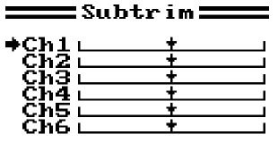

 Q: I'm working with the Tentacle Drivetrain Calculator to look at the performance of a few different motor options for a new antweight. I plan on using a 3S lipoly battery, but I'm uncertain of what value I should enter in the operating voltage field. Should I enter 12.6 as the actual resting voltage of the fully charged pack, our should I enter the conventional 11.1 volts that 3S lipolys are rated?
  Q: I bought a robot someone built: twin 24v motors and two 24v Victor 883 ESCs. No transmitter or receiver, but supposedly plug and play to put in. I'm researching that and have found a 6-channel system that may work - just waiting on few answers from the manufacturer.

 A: Mark J. You're talking about the "RX Battery" setup screen in the FS-i6 transmitter "Systems Menu" that sets parameters for receiver voltage telemetry. You can leave the settings as they are. Your receiver gets power from a regulated 5-volt supply in your Viper's tinyESC motor controllers. That regulated voltage does not increase with higher voltage main battery packs.
 A: Mark J. Out of the box the Q X7 supports only the FrSky ACCESS protocol, but the transmitter has a "Module Bay" on the back that accepts JR-style plug-in transmitter modules to allow use of various receiver protocols. Add a single or multiple protocol module supporting the AFHDS 2a protocol and you're good to go.
 A: Mark J. The diagrammed circuit will work just fine... until the link is removed. With the link gone the higher-voltage 6S battery will back-drive current thru the 4S battery to find a new path to ground:
 This will result in reverse current thru the drive ESC and forward current applied to the weapon ESC. Reverse current applied to the ESC will typically destroy the device, and back-driving a LiPo battery can be destructive as well. If you really want to run two batteries at different voltages you will need two power links.
 Q: My fairyweight has a Malenki-Nano ESC/receiver driving two N20 gearmotors and I'm having weird drive issues that I'm hoping to fix by mixing my Flysky FSi6:
 A: Mark J. The Taranis Q-X7 uses OpenTX 2.2 firmware that is a remarkably flexible, but the user interface is very different from standard transmitters. I just finished a full revision of the Team Run Amok "Programming the Taranis Q X7 Transmitter for Combat Robotics" guide. It has complete walk-thrus for:

 Q: My son is 10 and new to combat robotics. I am trying to help him with his FingerTech Viper kit, but have zero background in this hobby/field. He has his first battle next weekend, and suddenly the wiring for one of the parts doesn't work. He says that the wires are really sensitive and he can't get them just right so that they stay connected. I've included a picture of the part he's talking about. Is there something he's supposed to do? Thank you so much for your help. I tried searching the archives but wasn't sure what terms to use. Thanks again.
 Q: Why are the wheels spinning by themselves [Miami, Florida]
 A: Mark J. A bit of the history of R/C systems will be helpful:
 Q: My drive motors weren't perfectly in sync with my left motor moving forward slightly before my right motor causing a turn to the right instead of straight forward motion. I followed the process from your Transmitter Tweeks for Better Driving Control page to adjust the transmitter subtrims and solved that problem. Both motors now start up together when moving forward, but when I try a slow turn one motor will still start before the other.
 The Mix function is usually employed to adjust the position of a 'Slave' channel in response to the position of a different 'Master' channel but it is possible to set slave and master to the same channel to potentially increase the signal output range. The screen image at right shows what this type of mix would look like for Channel 2 on a FlySky FS-i6.

 Q: Hi again, this time having a problem with Lipos
 Q: About my recent question concerning chargers, I do have a fingertech, proper lipo charger, which came with the fingertech viper kit, but I don't know how to use it, and also my £3 BBB charged batteries much faster than 90 minutes when it worked. If my fingertech charger isn't suitable either, could you link me with a decent, working one with correct accessories and a video on how to use it?
Many thanks again!
Q: About my recent question concerning chargers, I do have a fingertech, proper lipo charger, which came with the fingertech viper kit, but I don't know how to use it, and also my £3 BBB charged batteries much faster than 90 minutes when it worked. If my fingertech charger isn't suitable either, could you link me with a decent, working one with correct accessories and a video on how to use it?
Many thanks again!
 A: Mark J. It's been a few years since I wrote the Beginners Guide to Combat Robot Gyros and your question gives me a good excuse to update the page. I've re-written the "Gyro Types" section to better discuss the merits of 'heading hold' versus 'rate' gyros in the modern era of powerful spinner weapons.

 Any idea how I can make a BEC-disabled Scorpion work? [Social Media]
 Q: For those of us still learning the ways of radio control, what would be the purpose of "mixing" and "inverting"?
  Q: I'm newer to building Bots. I finished my first antweight and I'm working at a beetleweight. I researched how to properly store the Lipos, so I keep them at proper storage charge in a ventilated heavy steel box. I have a pretty large house and I have the batteries in the all-concrete basement. I don't really know how much toxic smoke they would output of they "went off". Is it enough to go through my home ventilation system and kill everybody or what?
 Q: How many batteries for a heavyweight combat robot?

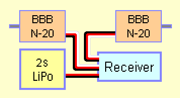 Q: About my question regarding the all-long SMEEEEEEEEEEEE would I be able to do this on an antweight scale with some of the Antweight N20 Red ESC that the Bristol Bot Builders sell by directly plugging the ESC into the receiver and plugging a 2S lipo directly into the receiver?
 A: Assuming that your receiver is OK with 7.4 volt input, yes -- that's exactly how the Red ESC is intended to be used.

 A: Didn't bother to read the link I provided, did you? A quick summary: current drawn by electric motors is proportional to the loading placed on them. You have information about your motors, but you need to know the wheel size, drive gear reduction, and physical details about your weapon in order to estimate motor loading.
 Run Amok Mixer Fixer
 Q: Hey, sorry in advance if any of this is super naive, but I'm in the process of building my first beetleweight, and I'm all but a beginner with electronics. I'm just messing around with it tonight, trying to make sure I understand something, but I can't seem to get it to work.


 A: Mark J. Those joysticks were part of the IFI Robot Controller System, as originally developed for the F.I.R.S.T. Robotics competitions in the late 1990s. Battlebots encouraged teams to use these 900 MHz controllers because they were less susceptible to interference than the 75 MHz hobby radios available at the time. The IFI system was bulky, complex, expensive, and had very limited control options. They were made obsolete by the frequency-hopping 2.4 ghz radios now in use.
 Why do I assume you want to use CH3? You didn't tell me about your transmitter or your weapon, but on a US standard twin-stick transmitter the Th rottle is assigned to the 'ratcheted' vertical axis on the left stick. That axis is not spring-centered, so you can set your weapon speed and leave the stick alone. The other channels are possibly less convenient:
 Q: is it better to wire the battery into the receiver or the esc? [Cupertino, California]

 That 5 volt power feed falls within the 'supply voltage' requirement of all hobby-grade receivers, and that is the voltage your receiver will 'see' as long as your main battery voltage remains in the range accepted by your ESC.
 Q: Hello. I need your help. I have a flysky i6x Transmitter and I have accessed the factory menu where I set on the self-centering option and the wherever is the throtle the connection between tx is made with rx. How can I undo that because I can't access the factory menu. Thank you. [Bucharest, Romania]


 Q: I'm having trouble setting up my new FS-i6 transmitter with my endbots desc. I set up the FS-i6 with elevon mixing according to the instructions in your FlySky FS-i6 Transmitter for Combat Robotics guide but I can't get the channels to behave. Moving the stick up with neither channel reversed, the right side moves forward and the left backwards. Reversing channel one has no effect, and having channel two or both reversed results in the left moving forward and the right backwards.
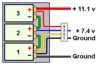 When tapping the balance plug for a voltage less than the full battery voltage, always use the full-pack ground (pin 1) on the plug. You could, for example, get 7.4 volts from the balance plug by tapping pin 2 and pin 4, but failing to include pin 1 creates the dreaded ground loop that shorts out one or more cells thru the receiver ground bus.
 Q: How do I charge a 36v Li-ion battery {link deleted] like those found in hoverboards? [Roseville, California]
 Q: I'm using a 20A Afro esc flashed with blheli to power a Turnigy 2209-980 brushless outrunner. I'm also using a Turnigy 850mAh 3 cell battery to power all the electronics. 30c-60c discharge. At low and high rpms, the weapon, when it gets a good hit on something, shuts off and re calibrates. I have installed a large capacitor between the battery leads that helps with this problem quite a bit. Anything above 50% power on the throttle shuts down the weapon when it gets a good hit. Rapidly throttling the power all the way up to 100% also achieves this.
 A: Mark J. Many combat robots use a single-axis 'heading hold' gyro to improve straight-line tracking and provide steady turn response. The solid-state gyro accomplishes this by adjusting drive motor speeds to make the actual turn rate (yaw) matches the turn commands coming from the R/C transmitter.
 Q: My son is making a 3lb battle bot. He wants to run the drive motors off of a 2s 300 mAh battery and run the weapon on a 3s 1100 mAh battery. I sent a sketch up of how he wants to wire it up. Somebody on [social media] said we would have a "ground loop" and I'd blow something up. What's a "ground loop", and do I really have a problem with this circuit? [Orlando, Florida]
 Q: Hi there. I purchased an Endbots DESC lemon to use in a Beetleweight project, but am finding acquiring a DSM2 transmitter in Europe troublesome. Is it possible to add a different receiver to the project to allow me to use an alternate transmitter? Failing that, are there any other dual channel ESCa that work well for beetles?
 A: Mark J. I'm glad that you are enjoying Ask Aaron! You have a choice of three types of R/C interfaces to control your pneumatic valve:
 Q: Is the goBILDA Element-6 Radio Control System any good for an ant or beetle?
  Q: I'm having some difficulty making a brushless saw weapon motor run off the Channel 5 switch of my FS-T6a radio. When I first built my 'bot I simply plugged the weapon ESC (Great Planes GPMM2130) into Channel 5 and when I flipped the switch the motor would reach full throttle. This has been working fine, but at the last event it stopped working. Flipping the Channel 5 switch now just makes the weapon ESC beep and twitch the motor. Plugging into Channel 6 gives a similar response on its switch.
 Q: I want to run the weapon in my new beetleweight at 6s [22.2 volts] but that's crazy high for my drive motors. What's the best way to reduce the voltage to the drive?
 Q: I'm building an antweight with a lifter plow, kinda like 'Duck!'. The lifter is powered by twin servos that need to run in opposite directions to work together on the lift, but my transmitter only has elevon mixing and I'm already using that for the drive motors. I have a Y-harness to connect both servos to a single receiver port. Can I re-wire one servo to respond in the opposite direction?
 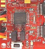 Q: Hey, its me from Anacortes again. I've run into a couple more hitches in the electronics of my beetleweight wedge. A while back you basically had to walk me through how to install the fingertech tinymixer properly, and at the time it seemed to work fine.
 A: Yea, the ESC is toast. All that heat is coming from the charred remains of the former BEC still trying to do something useful and mostly just turning current into heat. Here's what you do:
 Q: I've seen plenty of cheap lipo chargers on the market that you just plug the balance connector into and it starts charging. Yet with most higher end chargers they let you adjust the current going into them relative to the capacity of the battery. I assume thats in the best interest for the cells lifespan, but is there any risk in damaging the battery short term by using the first type of charger? [Roseville, California]
 Q: Hey I'm back! Another one of the problems I've been procrastinating about is that my Flysky FS-i6 transmitter has lately been maxing out the input one way or another when I barely twitch the stick. Since you seem to have quite a bit of knowledge about this transmitter, do you have any ideas of what I might do to fix this? Also, thank you so much for answering all of my questions. [Oak Harbor, Washington]
") A: You're welcome, Mandurah.
A: You're welcome, Mandurah.

 The ONLY fuse protection you should consider for your combat robot is a full power circuit fuse to keep your LiPo battery from going into thermal failure. This is required by some tournaments. A direct short caused by inflicted damage or catastrophic component failure in the power circuit will pull so much current from the LiPo that it quickly overheats and bursts into jets of smoke and flame, toasting your robot. For a properly selected battery, that level of current will be well in excess of the maximum draw expected from all the robot's motors under the most extreme anticipated conditions.
 A: Mark J. The usual approach to your design is to use a single battery of sufficient capacity to power both motors. The two ESCs are wired in parallel to the battery and draw power as needed.
 Q: It's me from Oak Harbor again with some clarification about my earlier question. The reason I am using two batteries is so they will fit into my robot, and I cannot use one of the ESCs to power the receiver, because the receiver has a power input port that is separate from the channel output ports. Could you show how a BEC would be added? Also, thank you so much for all the helpful advice that this site contains.

 Q: I want to build a switch! I'm looking at Team Whyachi's pictures and drawings on their website, and I'm confused as to how how they're able to use a metal socket screw to close the circuit. Even if there was a nylon washer separating the cap from the copper "bridge" and the two contacts, wouldn't the thread/screw body still touch and you'd get shocked if using a metal allen key? And how do they know how many turns it takes for full contact without overtightening the screw?
  A: Mark J. The Whyachi switch socket screw is completely isolated from the electrical circuit by a nylon 'top hat' grommet that extends thru the contact bar hole. The screw is isolated only to prevent the Allen wrench from accidentally shorting to another exposed electrical component. Direct current at normal robot-level voltages will not give you a 'shock' on touching a terminal -- you won't even feel it.
 A: Mark J. The only '3-volt' gearmotors I know of are made by Tamiya, and they are not nearly strong enough for the current level of robot combat. The motors are weak, the plastic gearboxes shatter, and the skinny little axles bend. Worse, I don't know of any electronic speed controllers that will work from a 3 volt power supply -- most won't operate below 6.5 volts. You'd be well advised to dump those motors and go with something more commonly used in combat robots.
 Q: I have a question on DX6i Spektrum transmitter. On the main board there is only 1 BLUE capacitor. I need the part # for this or the rating. With this part I will have a working radio, so help me out please? Thanks in advance. [Spur, Texas]

 Q: I'm currently doing the electronics for my 3 pound bot but I'm running into some issues:
 A: Mark J. Yes, it's fairly easy if you know your way around a circuit board. We can replace a knob's potentiometer with a 3-position ('center off') toggle switch and a pair of resistors that will give high/mid/low signal control.
 A: Mark J. The hamburger is bad. The answer depends on how precisely you need them to move 'together like one motor' and what type of 'dc motors' you use.
 Q: There's a bloke offering to group buy A123s on the Facebook [robot combat] group. Now this raises a couple questions given.

 Q: I am planning a heavyweight in the future and I need a 72 volt battery but can't find any good ones so maybe puttting a lot of small ones in would work. But how do you bundle up a lot of (relatively) smaller batteries in a pack to make 72 volts?

 Q: Hello, I have 2 questions. Bot info:
 The 20:1 ratio P60 gearboxes with the 2.375" wheels give the best performance from the RS-395 motors in a moderate size arena: around 5.5 MPH, reaching that speed in about 6.5 feet. That's ample speed and power to push around a big spinner weapon. The 26:1 gearboxes would be a little easier on the motors, but the 20:1 should be fine.
 The Orange R620 receiver has two failsafe modes on signal loss:


 A: Mark J. The control problems you're seeing aren't the fault of the 'tank steer' method. The problem is that most builders do not take time or do not know how to correctly adjust the features of their radio gear to provide smooth and precise control.
 A: No. Every component should be individually anchored to the chassis:
 Q: Hello Mark, this time I was wondering, just what is the best way to test a transmitter? The best solution I could come up with is sticking the robot in a fridge or cabinet and have it drive into the door so you could hear whether or not the controller penetrates the surface. Is there anything more reliable than that or no? [Kentucky]


 Q: Hey, I would like to consolidate some of my understanding on lithium-polymer batteries. If I want to run two separate batteries in together in a single robot, then the milliamp hours are not cumulative, but the voltage is -- am I correct? So, if for example, I run two 6,000 mah 11.1 volt batteries together, the result would be a 6,000 mah 22.2 volt power source? Do I also need to be wary of running the batteries in series or parallel? Thanks a lot! [Bellevue, Washington]
 Q: I've got hold of a piezo gyro and a mixer for use in one of my latest projects, and in order to avoid the 'death spin' I have a small r/c bypass switch that allows me to shut down the gyro when the robot gets flipped. However, as a result of this, the steering signal now goes through at least half a metre more wire than the forwards/backwards signal, as well as two separate electronic devices (the gyro and bypass switch), before it reaches the mixer. Will this introduce any delays or interfere with the mixer, and should I think about shortening the wires? [Scotforth, England]
 Q: Hi Mark. I have a question about running two speed controllers together. First a bit about my setup. I have 4 motors and want a "tank drive" setup using 2 2x12 sabertooth motor drivers. My transmitter/receiver is a FlySky FS-T6. I have searched high and low and can't seem to find anyone with a similar case, let alone a wiring diagram that is similar to my case. Most use 1 2x12 and drive only 2 motors.

 There is no need to split the channel 1 and channel 2 signal leads and run both signals to both ESCs. The left side ESC will get signal and ground from channel 1 (no 5v connection) and the right side ESC will get signal, ground, and 5v feed from channel 2. Note that the S1 and S2 connections on each ESC are 'jumpered' so that they both get the same signal input.

 A: Mark J. Assuming:
 A: Mark J. Lots of questions -- but that's why I'm here.
 Q: Hey Mark, I've been planing a new beetle weight after my first competition (An 8"x8" plate of steel with chunky lite flites) and I was planing on using modded VEXtrollers with the kitbots 1000RPM motors. The problem is that VEXtrollers don't have BEC built in, and I really don't have much money to buy a dedicated BEC of reasonable quality, so I was wondering if I could an off the self Radio Shack voltage regulator. If I can, what should I look for, but if I can't, why? There must be a reason why, because if they worked easily, RC guys would be using them. [Woodburn, Oregon]

 A: That's the way almost all combat robots are controlled -- two channels controlling opposite sides of the robot drive train.
 A: There is no on-line manual for this switch, and the instructions given on the web page are very sketchy. Since the power light is on and the status light blinks when you switch on channel 3, it sounds like the R/C link is correct and the switch is receiving the proper command from the receiver. So far so good.
 Q: Thanks for helping me in deciding radio control .I'm new to this r.c department so I decided to go for cheap one and In hobby king website I found turnigy,hobby king and orange rcs out of these three which is best for the begginers and easily programmable
 A: Wiring the packs in parallel has a few benefits, but if you want to keep the supply to each motor discrete there are a couple ways to do it:
 A: Each tinyESC has a battery eliminator circuit (BEC) that provides 5 volts DC to power to the R/C receiver thru the red wire of the yellow/red/brown flat cable from the ESC to the receiver. If you have two tinyESCs both attempting to power the same receiver there will be a feedback problem that will cause one ESC (sometimes both) to malfunction. This may very well be causing your problem.
 Q: Hi Aaron!! I want to know whether the twin stick RC system can be used in conjunction with relays to operate a robot. Thanks. [Mumbai, India]


 First, make sure the ESC connectors are plugged into the correct receiver ports - the ports on the Traxxas receiver are reversed! Channel 1 controls steering and channel 2 controls throttle -- plug the 'channel 1' ESC lead into channel 2 on the receiver, and plug the 'channel 2' ESC lead into channel 1.
 Q: I want to make an RC Helicopter so i want all relevant details apart from it i want to know about servo motors , 4 channel transistor and reciever. What all things would be requires and i also want some knowledge about transistor and reciever ?
 Q: Can you give me a diagram of how you wired Rat Amok?
 Q: Hi Aaron, how do i connect the channels in the R/Cs to the ESCs so that they control the robot and the weapon? and how do you do a "channel mixing"?
 A: Mark J. here: you can't directly judge the amperage capacity of a switch by the size of the wire attached to it -- but 20 gauge wire itself is rated for only 11 amps max. It is likely that any switch using such small wire would be rated for no more than 5 amps. Trying to push 35 amps thru such a switch will cause catastrophic failure very quickly.


 A: Mark J here: I'd suggest a Team Delta RCE220 Dual-Ended Switch in each robot. Hook each into channel 3 (throttle) on their respective receivers.

 Q: You are correct sir, I'm actually building a 1/10 scale D9 dozer. I know you don't deal with these models, however it's very similar to a robot and you are the only one that I've found that knows what I need to do. So here is what I have:
 Q: What is the voltage where NiMH batteries don't work properly?
 A: Mark J. here: Some readers may wonder why you want to do this. Servos can be 'hacked' to provide continuous rotation and used as drive motors. 'Overvolting' the servo will provide more speed and power at the cost of reduced lifespan. Many receivers and other R/C electronics, however, are very sensitive to increased voltage and can fail or malfunction if pushed to higher voltages. The trick is to run the receiver at a correct voltage while providing higher voltage to the servo.
 A: Mark J. here: hold on there, Cowboy... I'd say you were more than a little ahead of yourself. Nobody who's ready to build an autonomous combat robot is going to write to me and ask how it all gets wired up. Even if you can get your sensors, MCU, motors, weapon (you're missing a weapon controller), and remote activation R/C (you're missing that, too) wired correctly, the robot is just going to sit there without software. How are your programming skills?
 Q: How do I make a 'Y' shape in my wire?
 Q: I'm having trouble building a battery pack from four 'AA' cells. Can you please show me how it's supposed to be done?


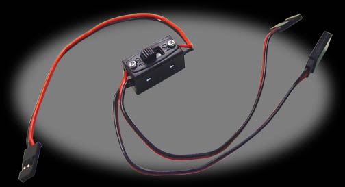