This page is one of several archives of 'Ask Aaron' questions and answers categorized by topic. To see the most recent questions or to ask a new question, go to the Ask Aaron Home Page.
Take a tour of posts in this Ask Aaron Archive that have been referenced to answer new questions. Click the 'Mystery Post Tour' button above to get started.
Date marker: January 2026
Another Indian Spinner
Q: I have a vertical spinner weapon in my bot how to calculate needed diameter of weapon and position of drive axis in length of my bot [Gujarat, India]
A: Mark J. Ask Aaron does not answer questions from builders competing in India.
Although I very much wish to support the technical aspects of robot construction in the energetic and expanding Indian subcontinent, I am also greatly worried that I may be contributing to an extremely dangerous situation for builders and spectators. This has brought me to a painful decision:
The 'Ask Aaron' website is closed to questions from builders competing in India
The best enclosed arenas in India would be considered inadequate for 30 pound robots in Europe or the US but are hosting events for 132 pound 'bots. Aaron certainly wouldn't approve of the reckless endangerment of life and limb, and I will not contribute to the development of robots competing in India until arenas in the region are universally able to safely contain them.
Q: Was Tip-Top (RW S5) the first gyro-walker? Tip-Top had no powered wheels. It used actuators to tilt a petrol-driven disc which would cause gyro, causing movement. Suprisingly, it was not considered a walker at the time. [Social Media]
A: Mark J. Tip-Top was not a gyro-walker -- the description at the Robot Wars Wiki is misleading:
The disc's axle was rounded on both the top and bottom, and long enough to touch the arena floor, which enabled the disc to balance on the floor like a spinning top...
When the disc was spinning at full speed, the actuators could be fired to tip the disc mechanism, and the resultant gyroscopic forces from the dome pressing against the ground would move the robot. This form of locomotion, nicknamed in the modern day as "gyro-walking".
'Tip-Top' and others of its ilk gain motion from the rounded end of the disc live axle rubbing on the arena surface. The tilting determines what part of the rounded end is in contact and thereby the direction and speed of travel. This method would work even better if the disc were removed and only the axle remained -- gyroscopic forces play no role in locomotion and actually impede the propulsion response.
Gene Burbeck's beetleweight One Fierce Low Ryda used this propulsion method quite successfully -- racking up a six-win/two-loss record at the 2008 Motorama tournament. Gene calls this style of propulsion 'wackerdrive'.
The earliest combat true gyro-walker I know of is Team Misfit's antweight 'Gyrobot' which first fought in 2009.
Try Elsewhere
Q: What controller would be best for robot sumo? [Maharashtra, Bharat]
A: Mark J. From a post two days ago:
Q: can i have information on sumo bot too?? [Bengaluru, Karnataka]
A: Mark J. Robot sumo is a whole different ball game. We claim no expertise in robot sumo -- there are better places to ask your questions.
For robot sumo questions you might try r/robotics on Reddit. You'll need to include information like weight class and a link to your rule set to get useful answers.
A Different Ballgame
Q: can i have information on sumo bot too?? [Bengaluru, Karnataka]
A: Mark J. Robot sumo is a whole different ball game. We claim no expertise in robot sumo -- there are better places to ask your questions.
A Rare Exception
Q: i am making a 15kg bot in which i have decided the specs for the bot should be:
Rhino 12V DC 100RPM 40Kgcm IG32 Heavy Duty Planetary Geared Motor
Rhino MDD 20Amp 6V-30V Dual DC Motor Driver (2 Channels)
FlySky CT6B 6ch 2.4GHz transmitter & receiver 1Km range
Astro Heavy Duty 75mm TPR Rubber HIgh Endurance Wheels (1"Wide)
300W 20A DC-DC Step Down Converter Module High Power Buck Voltage Regulator 6V-40V to 1.25V-36V
TecoKart Battery Cut Off Switch 12V/24V
24V DC Motor 2500rpm
i have decided to make a spinner weapon bot where the 24v battery would drive the spinner and the 12v are for wheels the buck converter would step down the voltage from 24v to 12v to drive the motor which would be connected to motor driver. Now i cannot find a compatible esc for 24v motor which would have braking functions. i can find the motor speed controller but they change the speed by potentiometer of spinner weapon but i want it with pwm compatible. What other alternative could i try for the spinner weapon and any other suggestion would be helpful. [Maharashtra, Bharat]
A: Mark J. 'Ask Aaron' has a general rule that we do not answer questions from competitors on the Indian subcontinent (
why not? )
- but I'm making a rare exception this time because:
You're building a fairly small robot;
You're not asking about spinner weapon design; and
You're going to have a very disappointing robot if you go ahead with those components.
Maybe I'm getting soft in my old age, but let's have a look at your parts list:
GenX 6S 3300mAh 40C/80C Lithium Polymer Battery -- You've told me too little about your spinner weapon for me to calculate the actual battery capacity requirement. The chosen drive motors will use very little power so this may be larger than needed. Assuming that you have a proper LiPo charger this should be OK.
Rhino 12V DC 100 RPM 40Kgcm IG32 Planetary Geared Motor -- Find larger motors This is a small RS-385 brushed motor with a peak output of about 15 watts. Rule of thumb has the ABSOLUTE MINIMUM drive power needed for a 15 Kg robot at 120 watts (8 watts per Kg) and a pair of these motors provide only 30 watts. With the 100 RPM output gearbox and 75mm wheels, the top speed of your robot will be a VERY slow 1.3 KPH (0.8 MPH).
I also worry about the durability of these gearmotors. The output shaft is only 6mm diameter, which is considered marginal for direct drive to a wheel in the 3-pound combat class -- it is far too small to survive in 15Kg combat.
Rhino MDD 20Amp 6V-30V Dual DC Motor Driver -- I don't know of any combat robots using this driver. Appears to be adequate to control the RS-385 motors, but not much more. You'll need an upgrade when you go to larger drive motors.
FlySky CT6B 6ch 2.4GHz transmitter & receiver -- Upgrade to the FS-i6 The CT6B is a very basic and difficult to adjust R/C system. For very little more you can purchase the FlySky FS-i6 system which is much easier to program, has many more control options, and does not require the added expense of a programing cable.
Astro Heavy Duty 75mm TPR Rubber Wheels -- These wheels will not attach to your motor output shafts without modification. They are designed to spin freely on an unpowerd shaft; the bearing must be removed and an adaptor hub fabricated to mate to your very small 6mm gearmotor shaft. That's a fair amount of work.
300W 20A DC-DC Step Down Voltage Regulator -- This is not needed A proper transmitter (like the FS-i6) can be programmed to provide reduced power to the drive motors via the motor controller. As your motor driver is rated for your full battery voltage you can use this trick. See this archived post for specific instructions using the FS-i6: you'll decrease the CH2 mix setting from 100% to 50% to get half-voltage.
TecoKart Battery Cut Off Switch 12V/24V -- WAY bigger and heavier than you need, but it will work.
24V DC Motor 2500rpm -- You have spec'd all the other components, but all I get here is a voltage and an RPM. I can make no comment.
Do you require "braking functions" on your 24 volt brushed motor controller to meet some weapon spin-down time requirement? I have never heard of such a requirement in Bharat. As you have provided no motor specs I can make no specific ESC recommendations, but I will mention that if you use a bi-directional ESC you can GENTLY apply a small reverse current to create a braking force and decrease the spin-down time.
All Fall Down
Q: I am making a 150 g grabber robot that clamps onto other robots and pushes them into a pit, and since our competition mostly consist of zippy vertical spinners, i am using two 1200 rpm motors to catch up with them. To prevent the robot from tipping while driving fast, I have placed the battery near the front of the robot. However [I'm concerned that] when I drive the other robots into the pit, I also fall in due to the far-forward center of mass (I think). How can I optimize my robot for not falling into the pit? (My robot consists of a bent metal box with wheels and two metal forks.) [San Diego, California]
A: Mark J. The description of your robot is quite sparse. You say it is a grabber, but only mention two metal forks, a metal box, and an unspecified number of wheels. Is there a servo powered clamp? I'm imagining a design something like 'Jawbreaker' from 'Robotica' (pictured below).
A few general comments:
You probably do not want or need to mount the battery in the front of the robot. See Where Does it Go? one post down this page for guidance on weight distribution to prevent nose lifting under acceleration.
If two robots go into a pit together, most competitions award a win to the robot that was in control when they went in. A two-wheeled clampbot will most often follow its victim into a pit.
A longer four-wheeled clampbot can have a center of mass far enough back to allow it to safely approach a pit and drop in an opponent without tipping itself in as well -- if that's what you actually need.
I'll need more information about your 'bot to give more specific advice.
Reply: Thank you for your feedback! Here is a sketch of my robot:
A: The render helps. Your design has very little weight on your drive wheels. When you add a good chunk of your opponent's weight onto the front forks you're going to have very little traction to push your opponent around and real difficulty in executing a turn. I would suggest smaller diameter wheels moved well forward so that an opponent clamped above them could add weight and improve traction. You might need to extend the forks upward to keep your trapped opponent away from the wheels if the new wheels extend too high. That should give you enough maneuvering control to set them right on the pit edge and drop them in.
I'd also add a rubber tip to the "grabber". Your motor is unlikely to have enough power to get that sharp point to dig in and hold.
Reply: According to SPARC, if the robots are stuck together when entering a pit they will be separated and taken back to the arena. If I am still clamping the robot on my dustpan will the count as us being stuck together?
A: There are two paragraphs in the SPARC Match Rules covering this situation. The first says whoever goes in first loses:
If the arena is equipped with a Death Zone/Pit/Push-out or similar hazard a robot entering this area in a one-on-one match will result in the end of the match and a loss for the robot that first entered the area.
It's just like a sumo match: whoever first touches outside the line loses and the match is immediately over. That is the common rule in robot combat and it makes universal sense. However, two paragraphs farther down in the rules is a paragraph that confuses the issue:
In the event that both robots enter the death zone simultaneously they will be returned to the combat area and the match will resume. A robot that places its opponent in the death zone must be able to do so without also becoming stuck itself. If it is not able to separate
from the other robot this will be treated as simultaneous entry.
Different event organizers interpret this paragraph in different ways. Some interpret this rule as only covering cases where the 'bots are literally stuck together. Others will reset anytime both robots end up in the pit. It varies from one event to another so it pays to clarify this with the organizer of your specific event.
Where Does it Go?
Q: You've said that a two wheeled robot should have 65% of the weight on the drive wheels. My CAD program gives me the location of the center of mass but where do I place the mass center to put the right amount of weight on the wheels? [West Sacramento, California]
A: Mark J. For best traction you want as much weight on the drive wheels as possible, but leaving too little weight on the front of your 'bot will allow it lift up off the arena floor under acceleration and make it vulnerable to attack. Designing for 65% of the robot weight on the drive wheels gives good traction and leaves enough front weight in most cases.
To place 65% of the weight on the rear wheels:
Measure the distance from the weight-bearing point of contact at the front of the robot back to the axles of the drive motors;
Move components as needed to place the mass center at a point 65% of the way rearward along that measured line -- see illustration above.
Note 1 - Robots with unusual layouts or odd dimensions may require different axle weights. Page 46 of the RioBotz Combat Tutorial has a discussion on calculating optimum placement of the center of mass based on traction and the height of the mass center.
Note 2 - Magnet downforce may be used to correct traction and lift problems in a steel-floored arena. Combined gravity and magnetic weight of 65% on the drive wheels will still be a good starting point.
The Tools You Know
Q: I'd like to get started in combat robots by building an antweight. I've asked about getting started on [social media site] and people there tell me to use a 3D printer. I don't have access to a 3D printer so is there another way to build a simple robot? [Southern Germany]
A: Mark J. Builders who regularly use a 3D printer get that method stuck in their head.
"If the only tool you have is a hammer, every problem looks like a nail."
- Abraham Maslow, Psychologist
The above saying describes the tendency to rely too heavily on a familiar tool or method, even when it's not appropriate for the situation. It highlights a cognitive bias where people apply a single, known approach to various situations, potentially overlooking more effective alternatives.
3D printers have a large up-front cost in terms of both skills and expense. Once you have paid that price the printer becomes a quick and effective tool. But if you have not paid that price it is more effective to use techniques and skills with which you are comfortable. You can build a simple robot simply by gathering compatible components, bolting them down to a stiff baseplate, and adding protective structures and offensive capability as you see fit.
I'll also point out that there are combat robot kits -- with or without a chassis -- that allow you to quickly construct a functional combat robot you may later modify as you see fit.
Two Versus One
Q: How is a control bot supposed to deal with a multibot?
My local competition recently added a multibot bonus mirroring the one found in NHRL, and I plan on competing with a control bot. Assuming competently designed, built and driven 'Bots on both sides, I can't think of a way to deal with them whether or not they are themselves control bots or have some sort of weapon. [Shore of the Mediterranean]
A: Mark J. I had no idea that there were combat robot events in your country. I found photos from the April event that showed a nice arena, good attendance, and some interesting competitors. Congratulations.
It kinda bites to be a control 'bot under the current rulesets. Not all design challenges have solutions:
How do you beat Paper with Rock?
How do you beat Rock with Scissors?
How do you beat Scissors with Paper?
I'm not a fan of the multibot weight bonus, but you fight under the rules as written. You could build twin control bots, or add a small wedgebot to cause chaos. You could pick up one bot and use it to beat up the other 'bots -- I once did that with a control 'bot in a hobbyweight rumble (full story). Be creative and have fun -- fun is as good as winning.
A Lot of VEX Parts
Q: Hello, I am currently designing a 30lb combat robot and have 3 main questions. To start, I have added a small photo of the design so far to give an idea. The goal is to have a vertical spinner design, that has a 4 wheels driven by two motors. I am running an 8s system, with Talon SRX and Redline 775 + 10:1 planetary gearbox for the drive. And a Castle 2028 800 Kv and Mamba Monster X 8s for the Weapon. The Talons are technically only rated for 28V, but have been tested and work at 30V while mixing the output to 40% for the 12V redlines. We do have 8s ESCs but they are almost double in size and would be much more difficult to design the plating around.
I know this is a lot in one post, but I know you're the guy to ask. So let me know your thoughts on my setup. [Mount Prospect, Illinois]
First off with just the specs I would be curious any advice for the design just based off the electronics and CAD photo.
A: Mark J. I see that you have made some changes to your design since your earlier post. A few observations:
I'm personally not a fan of overvolting ESCs. A LiPo cell has a nominal potential of 3.7 volts, but when fully charged it sets at a resting 4.2 volts. That means your 8S system can push 33.6 volts thru your Talon SRX. I can hear the capacitors failing already. Still feel confident?
A Castle 2028 weapon motor is massive overkill for a featherweight -- particularly given that your weapon itself appears to be on the small size. A typical featherweight weapon motor weighs in at about 21 ounces (4.4% of the robot mass), whereas the Castle tips the scale at 44 ounces (9.2% of the robot mass). See: Brushless Motor Selection.
Spinning weapons are flywheels. They rely on rotational inertia to collect energy from a continuous power source (electric motor, internal combustion engine...) over time and store it as rotational kinetic energy. On impact, the flywheel releases the stored energy in a blow that far exceeds the energy directly available from the continuous source.
Having a huge motor paired to a weapon too small to store a significant multiple of the motor's output power at a reasonable rotational speed is not a path to victory. Cut the motor weight in half and add the mass to the weapon. See: Ask Aaron Spinner Weapon FAQ.
Your design makes VERY little effort to 'feed' your opponent up and into the rotating weapon. Your plow is far too steep and elevated to 'win the ground game'. The current spinner design 'meta' employs floating forks to get under the opponent and lift their leading edge up into the weapon path where the weapon will get excellent 'bite' and deliver a massive hit. Without forks your weapon is set up to strike a glancing and ineffective blow on some smooth surface of your opponent.
Can I assume there is a chain or belt drive running from the rear wheels to the fronts to provide four-wheel drive? If not, the rear wheels by themselves have very little weight on them which will result in poor pushing power, reduced acceleration, and impaired maneuverability
I wonder what events you plan to enter with this 'bot. You are using a lot of VEX parts that are common in non-combat robotics in preference to components in use by successful combat competitors. This seems a little odd.
I have additional comments, but they fit well into the answers to your other questions below.
Q: Getting into my questions though, my first is about the drive. In another post you said that Featherweights should be around a 20:1 drive system. My first question is, if I have an arena that is utilizing a steel floor, and I add magnets for extra down force, would 10:1 be suitable? Or does the extra downforce not affect the torque?
A: It is not a matter of "Featherweights should be around a 20:1 drive system" -- different drive motors will require differing gear reductions for any given combination of robot weight, wheel diameter, and arena size. See: Optimizing Drivetrains.
You have the relationship between traction and gearing reversed. Adding magnetic downforce to a robot creates a need for greater torque from greater gear reduction -- not the other way around. The Team Tentacle Drivetrain Calculator includes a field to enter magnetic downforce and can calculate adjustments to the drivetrain requirements based on that added traction.
Q: Another comment about the drive system, is when running the redlines and gearbox at 12v, they seem to get hot very fast. Besides adding a cooling fan, is there an easy way to dissipate the heat? Would 3D printing a TPU heatsink be beneficial? Or maybe it isn't a concern since the matches are only 3 mins max.
A: As noted in my answer to your earlier post, AndyMark Redlines are quite commonly run at 6S voltage in combat robots . If run with a reasonable gear reduction they can handle the heat. If run with insufficient gear reduction they will melt. Wrapping them in a TPU heatsink would be worse than doing nothing as TPU is a much better insulator than heat conductor.
Q: Another question I have is about the weapon system. I am trying to decide whether it would be better to have the bearings spin on the inner or outer ring. The main difference in setup would be spinning the Weapon + Shaft, and attaching the bearings to a side plate. Or attaching the bearings inside the weapon and spinning it around the stationary shaft. I am not sure which would protect the bearing most from impact, as well as produce the most RPM/Inertia.
A: There are essentially no differences in bearing protection. speed, or rotational inertia between a Live Shaft that spins with the weapon and a Dead Shaft that is fixed relative to the chassis. The primary difference is that a 'dead shaft' can be a structural member of the chassis that adds to both the strength and rigidity of the robot.
Q: Along with that, I've done a lot of research on bearings and have heard a lot of good things about angular contact bearings. But did not know the best type for high RPM yet high force.
A: Angular contact bearings (expensive) are used where a single bearing must absorb forces from all directions. This is not the case for your weapon. A pair of tapered roller bearings (much less expensive - and stronger) will do very nicely.
Some builders prefer oilite bushings for their weapons. These bushings can absorb huge impact loads and are inexpensive -- at the cost of a bit greater friction.
Q: My third question [You and I count differently!] is about bolts/tapping plates connection. I currently have 1/16", 1/8", 1/4" and 1/2" aluminum to work with for plating. I also have M3, M4, M5, M6 bolts to work with. In my design I wanted to countersink my bolts so that I didn't leave an exposed bolt to be sheared off by the enemy weapon. But my main confusion is the best combination of these. Because say if we use a 1/2" plate, the bigger the bore a tap we make, the less wall material we leave to support the bolt.
Q: Hey, this is my first time trying to design a robot and build it completely from scratch. My competition is on April 29th and it is currently February 12th. I have done all the calculations for drive train. So now I am learning how to use fusion 360 and recently started designing.
Is it bad that I still don't have a CAD design?
Can you give me a time frame of how I should do things up until April 29th?
Any tips? [Chicago]
A: Mark J. Your event is on a Tuesday? Does that make this a school project?
It would help to know a bit about the robot you're building. Different designs, different builders, different shop tools, and differing experience levels all call for differing timetables -- but I can give some general advice.
Delays in receiving parts or receiving faulty parts can scuttle your schedule. Order your parts as soon as possible and test them on arrival.
It's a good idea to have one or more experienced builders take a look at a sketch of your design and suggest changes based on their experience. There are several online forums suited for this purpose -- as well as 'Ask Aaron'.
If this is a school project the CAD may be a requirement, but many combat robots have been and continue to be fabricated without Computer Aided Design. You can gather your parts and use "Cardboard Aided Design" to construct a mockup of a robot and make sure everything fits before commiting to chassis dimensions and layout. See FAQ #7 and the photo of a cardboard chassis mockup below.
Simple robots win. A chassis made from blocks of UHMW polyethyene held together with long wood screws is simple, durable, and easy to construct. Add top and bottom covers and you have a viable chassis. Below is a photo of "Cloud of Suspicion" with the top cover removed.
Schedule time between completion of the robot and the event to become familiar with operating the robot and finding things that need to be changed. About a week is not too much time for this. Spend some of that time adjusting the settings on your R/C transmitter for improved control. See: Transmitter Tweeks for Better Driving Control
Date marker: January 2025
Traction and Reflex Limited
Q: Hello,
If I want to make a competitive plastic ant with oversize drive motors, would you recommend brushed or brushless? Palm Beach Bots recently added a couple of brushed and brushless beetle drive options that both seem light enough to put in an ant, as well as the new dual brushless drive esc that was just released. This robot would most likely be a 4wd vert or 2wd drum with a hub motor powered weapon.
Do you think this would be practical overall? It would gain a lot of pushing power and speed but I feel like I would see more people oversizing drive components if it was worth doing. I'm sure I can make everything fit, but figured I should ask before I buy any components. Thanks! [Logan, Utah]
A: Mark J. You are wise to note that oversize drive motors are not commonly encountered. If big motors gain an edge in pushing power, why isn't everyone using them? If speed is a sure path to victory, why are chunky brushless drive motors so rare?
Pushing power is limited by traction. Once the wheels meet their traction limit additional drivetrain torque does not increase pushing power. The maximum pushing force a robot can generate is dependent on the weight bearing down on the driven wheels and the traction of the tire/arena pairing:
Maximum pushing force = Weight Supported by the Drive Wheels × Coefficient of Friction
An oversized drivetrain will "break traction" and spin the drive wheels at a small fraction of its power, but will not by itself generate additional pushing force from the tires. If you are fighting in a steel-floored arena and event rules allow it you may use chassis magnets to increase the apparent weight on the drive wheels and make use of increased motor power -- but there are significant problems with magnetic downforce, as described by multiple posts in the Ask Aaron Archives.
There is only so much speed that can us effectively used in an insect-class arena. Like pushing force, acceleration force is also traction limited -- excess torque will break the tires free and hamper directional control of the robot. Even small ant brushless drive motors like the 24 gram Repeat Mini Mk3 deliver more speed and power than most drivers can use. Oversized drive motors will simply increase your frequency of running into the arena walls.
To answer your questions:
For the reasons above, I do not consider oversized beetle drive motors in a plastic ant to be practical.
Unless you have significant experience driving insect-class 'bots and reflexes like an over-caffeinated cat, I would recommend a nice pair of Repeat Drive Brushed Mk2 drive motors.
Q: Hey, Oversized ant drive guy here again, good call on the traction, I hadn't considered it. However, I have thought of one more point.
Since spinning weapons get more bite the faster they charge at something, would it be practical in that way to increase drive speed? Most of my successful robots have essentially been fast glass cannons that rely on outmaneuvering and ending the fight without taking damage. In this way, would it be wise to have an oversize drive to allow for faster retreats and a hit and run style strategy? Or perhaps just the antweight size brushless drive options?
I've mostly used the repeat brushed mk2's, but do have a set of mk3 mini brushless motors on hand. The brushless seem to not perform as well, but it might be due to them being paired to some of the very first brushless drive esc's that were released.
Thanks as always for the knowledgeable perspectives!
A: Brushless motors are only as good as the controller firmware and setup. Trying to control them with ESCs not perfectly matched to their requirements will yield very poor results. I like brushed drive motors because they're stupid simple to set up.
As mentioned in the post above, acceleration force is also traction limited. All torque above the physical traction limit will simply set the wheels free-spinning without adding to acceleration. More power won't give you as much improved performance as you think, and the effect on robot control can be catastrophic. The Tentacle Drivetrain Calculator takes this traction limit into account when modeling robot performance, so let's use it to compare the performance of two ants powered by normal and oversized motors.
The robots are two-wheel drive with 2" diameter wheels and 3S LiPo batteries. The only difference is that one is powered by the familiar Repeat Drive Brushed Mk2 ant motors while the other is powered by the more-than-twice as powerful Repeat Compact Brushed motors. Both are modeled for a 6-foot sprint across the arena floor:
For the six-foot sprint, the 115% power increase results in:
A speed increase of 5% from 5.96 MPH to 6.25 MPH.
An elapsed time decrease of 14% from 1.08 sec to 0.95 sec.
Do you think that's worth the effort? Even if the additional power did not adversely affect robot control, I would say not.
Feeling Overwhelmed
Q: Designing my first bot and have watched quite a few videos on it, but still feel overwhelmed, I'm aiming for a 1lb plastic since it sounds like the easiest to get into, and I want it to be a shuffler for the .5lb bonus with a spring powered hammer so it's at least a little unique.
I'm trying to figure out how to set up the electronics for fairly cheap and it sounds like a good start is a dual brushed ESC with two high ratio n20's but n20 motors say they are rated for 6v so is the 7.4v-8.4v of a 2s too much for them? I know there are better motors but I don't feel comfortable buying multiple $20 motors without a bit more understanding and I'm pretty sure a BEC can't provide enough current for running a whole bot.
I already have a Flysky controller and receiver, so I only need a power switch, esc, and motors. I thought that the most economical solution would be a Fingertech switch ($7), Repeat Electronics 'Budget Ant DESC' ($15), but then got stuck at the motors since the cheapest reliable motors I saw were $20 a pop which felt like a lot since I'd probably need three for the drive and hammer, can I just buy a few pairs of cheap n20's for $5 each and not have to worry about them failing immediately?
And for the hammer I'm going to canibalize a cheap servo that I already have, then throw some extra mosfets on it to run a snail cam that can safely charge and discharge the hammer; so I don't need an esc for the weapon motor. [Northern Arizona University]
A: Mark J. So, for your first 'bot you've decided to build a plastic ant shuffler with a pair of the cheapest N20 motors you can find on a mild voltage boost dragging around a cam-and-spring hammer weapon controlled by a cannibalized cheap servo board with extra MOSFETs. I wonder why you're feeling overwhelmed?
A 2S battery is fine for N20s; I've seen them run higher. You won't have to run a BEC to drop the voltage to your drive motors.
A pair of $5 N20s is marginal for a 16 ounce 'bot, and a shuffler system places a great deal more stress on the drive motor than do nice round wheels. A shuffler has to keep fighting gravity to raise and drop the robot as it runs -- much like like triangular wheels. If you want to use N20s at least use a pair of good ones.
Ask Aaron was founded to help builders create successful competitive robots. For some builders 'success' comes from impressing other builders rather than winning matches. To each their own.
Longest Internal Diagonal
Q: Can my 30lb thwack bot be 6 feet long in NHRL? I heard that the longest it could be was 3 feet but I don't know if I read it right so I'm super confused. [Social Media]
A: Mark J. Just to make things complicated, the NHRL has a 'cube rule' for dimensions:
"12lb and 30lb robots must be able to fit into a 36 x 36 x 36-inch box."
The 'bot does not have to sit flat on the box floor -- design your 'bot to fit into into the longest internal diagonal of the box and it could have a maximum dimension up to ( 32 + 32 + 32 ) 0.5 ≈ 5.2 feet. Plus, there is a loophole that allows even greater length:
"Once the match begins, robots are allowed to expand or contract to any size."
If your 'bot can unfold of otherwise expand when it starts moving it can become much longer.
Make Two Like Four
Q: I've been seeing robots like Swamp Thing and Sawblaze be able to ram other bots while being 2 wheeled. What is it that is done for 2 wheeled robots to be able to push and ram other bots similar to 4 wheeled ones? [Somewhere on T-Mobil]
A: Mark J. What is it that is done to arrange words into a beautiful sonnet? There is no one thing done to enable precision control and pushing power on a two-wheeled 'bot -- there is a long list, and you have to get everything on that list right. Here is part of that list:
Tires that are a good match for high traction on the specific arena surface.
Carefully designed and refined forks and/or a plow to "win the ground game".
If on a steel arena floor and if allowed, a few carefully placed and reasonably sized magnets.
Center of gravity placed for best two-wheel traction: see page 46 of the RioBotz Combat Tutorial.
A carefully set-up R/C system that responds well to the driver's inputs, a well-practiced driver, and possibly a peizo gyro.
You'll go thru a long process of trial and refinement to get these things right. You may have noticed that the 'bots you mentioned are built by highly experienced teams.
Frequently
Q: how to desing a
beetle weight bot [Puducherry, Bharat]
Q: I have a gear ratio question. My son started designing his first Beetle and wanted to have big wheels in back and small wheels in front. The back wheels are direct driven by the motor. What is the formula for calculating the timing pulley sizes on the front and back wheels to match the overall outer diameter rpm's of each. My assumption is a smaller pulley in back and larger pulley up front on the smaller wheel.
A: Mark J.
The smaller wheel requires the smaller pulley. When driven by the larger pulley it will spin faster to 'keep up' with the larger wheel.
The ratio of the pulleys is the same as the ratio of the wheel diameters. Here is an example calculation for 2.5" diameter rear wheels and 1.5" diameter front wheels with a 30 tooth pulley on the rear:
Teeth on Front Sprocket = Teeth on Rear Sprocket × Front Wheel Diameter ÷ Rear Wheel Diameter
Teeth on Front Sprocket = 30 Teeth × 1.5" ÷ 2.5" = 30 Teeth × 0.6 = 18 Teeth
The Axle Does Not Spin
Q: Some shell spinners (Ziggo, Mega/Gigabyte) have a pole on top that doesn't spin with the shell. How are those attached? I'd expect the shell to spin on an axle that would have to be mounted exactly where the pole is mounted instead. [Beavercreek, Ohio]
A: Mark J. The top pole is an extension of the non-spinning weapon axle. The images below show 'Megabyte' with and without the weapon shell mounted.
The weapon axle is a large diameter non-spinning "dead shaft" attached to the chassis base and supported where it passes thru the top of the chassis.
In the 'naked' photo you can see the tall weapon hub with integeral bearings riding on the dead shaft.
The hub includes a pully that is spun by the weapon motor via twin V-belts.
After the shell is bolted to the hub, the top pole is clamped onto the axle stub that extends above the weapon hub.
Shrink It and Watch It Move
Q: This isn't an 'Ask', more so an 'Answer'. I've seen a few people come here to ask about building shufflebots, so I decided to make a GIF showing how they work. I used Opentoonz, a free animation software. I hope you like it!
- sincerely, an intermediate animator : ) [West of San Antonio ☆]
A: Mark J. Prescient of you, Icey. I was just about to post the question below when your shufflebot animation arrived. If you're going to continue working with gif animation you'll want to know about Ezgif.com. Using this site I was able to edit your animation (remove excess frames, increase use of transparency, crop, shrink, change the frame rate, and gif optimize) to reduce its size from 105K down to 18K. You can also add text and rotate the gif. Very handy.
Q: Hey there! I am a relatively new combat robotics builder that has just recently completed my first beetleweight robot named 'Faraday'. It's my own take and attempt at the design concept of "Monkfish", a very successful beetle which features a horizontal undercutter along with a shuffler drive mechanism.
I've worked on this robot for nearly 2 months now prototyping and testing the shuffler drive to work well. One of the main things I'd love to work more on is the shufflers, and specifically trying to improve the linear drive speed. While it's not slow, it's nowhere near the top speed of many other robots (including some other shuffler robots). Most of the dimensions currently present are either just assumed to be reasonable values or found through some testing.
I've done my best to work on figuring out the mechanics and math behind the cam system, including trying to find resources online, but it's been frustrating since there appears to be very little available for what I'm attempting to optimize here (lateral speed of the foot, primarily), since the slotted single cam mechanism appears to be used for very different applications in industry. Searching through the Ask Aaron archives yields extremely little regarding shuffler information so I thought I might as well ask if you had any sort of knowledge to start more work off of. I am currently using Repeat Compacts for the drive running at 4S, but I may look towards better motors in the future.
Thanks for your help. Your site has assisted me an extraordinary amount over the past couple of months while I am learning more about combat robotics.
Ryan D. [Terre Haute, Indiana]
A: Mark J. I've spent more than a bit of time contemplating the mysteries of the shuffledrive and I've found that optimization is simpler once you realize that a shuffle mechanism is simply a well disguised lumpy wheel. A classic three-plate shuffler propels the 'bot as would a triangular wheel with a 'radius' equal to your cam offset:
At slow rotational speed, a triangular wheel lifts its load by 1/2 the radius and allows it to drop back down three times per revolution. That wastes a lot of energy.
As speed increases the wheel load does not have time to fully drop back down onto the 'flat' of the triangle and the wheel loses contact with the floor for part of each rotation.
As speed continues to increase, the time of wheel contact further decreases. You cannot add to the forward speed of the 'bot with a wheel that is not in contact with the floor, so the benefit of a faster wheel rotation limits itself.
The greater the number of plates, the rounder the "disguised wheel" becomes: four plates equals a square wheel, six plates equals a hexagonal wheel, and so on. The rounder the 'wheel' the greater the amount of time it will spend in contact with the floor, and greater contact time equals greater opportunity to propel the 'bot. A shuffledrive with an infinite number of plates would perfectly emulate a round wheel.
'Faraday' appears to be a near-perfect copy of Monkfish and their 'pinned slot' shuffle variant which decreases the wasteful 'lift' phase of the cycle and extends the lateral motion, but other builders have further improved on this design. Take a look at at the article Experimentation in Shufflers by Absolute Chaos Robotics for an up-to-date review of shuffle design evolution. This short video of Jamison Go explaining a few points on the Silent X shuffledrive may give you some ideas.
Over But Not Back
Q: Hi, Its ghost with backyard bots again.
it's been fully printed out, and in testing, I give it the throttle and..... it flips over
I reverse, trying to flip over again, and it doesn't. why is this the case? [Close to Raleigh, NC]
A: Mark J. I'm having a hard time imagining that your fully assembled 'bot with that heavy direct-drive weapon hanging out in front is flipping over at all. Perhaps the center of gravity is so high that it is causing trouble.
I have previously directed you to Section 2.2.7 of the RioBotz Combot Tutorial for their formula to optimize weight distribution for best traction for a two-wheeled 'bot while keeping the nose down. That should apply in either direction. Some thoughts:
You may have inadvertently set up your single-stick mix to provide less than full power in reverse.
If the 'bot won't flip over when inverted maybe you should reverse your throttle channel response and weapon direction to run it inverted.
Have you tried 'blipping' the weapon for a little torque reaction to help it flip back over when inverted?
You've previously asked about magnets. Some VERY SMALL magnets embedded out near the tips of your forks can add enough downforce to keep the 'bot steady on a steel floor.
Reply: Thanks for the advice! Turns out it's the screwheads, they are just long enough to keep us from flipping back over. Our competition is this weekend, but after that I'll definitely try some of those suggestions! Unfortunately, magnets are a no-go with the non-metallic floor arenas that are popular here.
One Hinge Leads to Another
Q: Are "double hinged" wedgelets more effective than regular ones? I've seen them used on 'RotatoR', but (just from personal observation) it doesn't seem to out-wedge opponents any more than other bots with forks.
- sincerely, Iceywave [West of San Antonio ☆]
A: Mark J. I don't believe that double-hinged wedges as sometimes seen on multiple competitors are intended to directly win 'the ground game'. I believe their purpose is to allow specific wedgelet designs to glide more easily over imperfections in the arena floor while still presenting a ground game to match their opponents. The technique may be particularly useful on invertible 'bots.
Mathematically...
Q: mathematically (not realistically, I do not want to know if it is realistic or not, just want to know your take) what is the best combat robot design for a combat robot, with a combat robot being 1, 100, or 250 lbs, and best is the greatest advantage of the following:
drivetrain: wheel material, motor type, amount of wheels, and type of wheels (mecanum, omni, standard, swerve etc)
weapon: size, material, type, speed, profile etc. etc.
armor: material, thickness, and most importantly, angle.
assume that you can hold a very precise RPM, and traction is not an issue.
assume that you are using a common transmitter, receiver, ESC that do not have a chance of falliure.
assume as well that any type of battery is allowed and that it goes perfectly.
what would be your design? - Backyard Bots [Close to Raleigh, NC]
Q: With car-steering being obsolete in combat robotics for the past two decades, would you say there are any advantages to using it (as opposed to tank steering) in modern times?
While we're on the subject, was Run Away! the last combat robot to use car-steering?
-sincerely, Iceywave ☆ [West of San Antonio]
A: Mark J. Realtively few combat robots have used automotive-style 'pivot steering', but many fans are surprised to hear that Combat Robot Hall of Fame members 'KillerHurtz' and 'The Judge v1.0' had steered front wheels. Stability in a straight-line and the ability to hold a smooth turn radius remain good reasons to consider the design, although the development of solid-state gyro controllers has brought similar control to skid-steer 'bots.
The last pivot-steered robot I'm aware of was Team ICR's middleweight 'Trainwreck' from Sandusky Ohio. They fought in Comedy Central BattleBots seasons 3.0 and 5.0, winning two matches at the latter event. The 'bot went on to compete at Michael "Fuzzy" Mauldin's Robot Club & Grille where they were the #7 ranked middleweight for the 2002/2003 season.
It's a Zen Thing
Q: If the first design you should build is a wedge, what's the second? [Saratoga Springs, Utah]
A: Mark J. When you have built and competed with your wedge you will better understand:
The magnitude of the challenges presented by differing types of weapons; and
How well your knowledge and skill level suit those challenges.
Your next step will be obvious.
Zen teaches that enlightenment is achieved through the profound realization that one is already an enlightened being.
Red, Blue, and Purple
Q: I'm probably being paranoid, but can an average person unscrew a bolt that's already been secured with mid-strength threadlock liquid? I can't think of a more embarrassing way to lose than forfeiting a match because you can't replace your robot's damaged armor panels. [West of San Antonio ☆]
A: Mark J. I can think of several more embarrassing ways to lose a match, but I won't list them here. From the manufacturer's website:
LOCTITE® blue threadlocker is medium strength threadlocker adhesive. This product cures fully in 24 hours and... is removable with standard hand tools on 6mm to 20mm fasteners.
For smaller fasteners, the manufacturer recommends their low strength threadlocker:
LOCTITE® 222™ purple threadlocker... can be used on metals such as aluminum and brass and offers a lot of flexibility to the user. Due to the threadlocker being low strength, it can be removed with the same tool used to put the project together. It is... especially efficient with very small screw applications, less than 1/4 inch in diameter.
Real World: I've never had trouble disassembling small steel fasteners that used blue threadlocker. Use a small amount. If it won't come apart add heat. Don't use red, blue, or purple with plastic.
Q: Also, sorry for my recent posts not being very Ask-Aaron-Mission-Statement-ey™. I got a "little" (put "little" in a slanted font) carried away, but I'll do better from now on.
A: Not a problem. I enjoy your posts, Icey. I also enjoy popcorn, but when there is so much popcorn that I can't find the TV remote I have to sweep the popcorn into the special popcorn room.
Q: But I do have one favor to ask before I go. Could you please change all mentions of the word {something incomprehendibly random} on this and my previous post to something incomprehendibly random? : )
-sincerely, Iceywave☆
A: I told my fave AI to globally replace {something incomprehensibly random} with {something incomprehensibly random} but it apparently found all of runamok.tech to be {something incomprehensibly random} and I had to restore the site from a backup tape I keep down in Deep 13. Unfortunately I can no longer remember what word I was replacing with {something incomprehensibly random} as it was replaced by {something incomprehensibly random}. Sorry.
The Ugly Vibrating Brick
Q: I was reminiscing about Robot Wars with an old friend and trying to find a visual representation / schematic that describes how DRILLZILLA operates [i.e. Its magnificent shufflebot mechanism]. Help? [Mexico, Missouri]
A: Mark J. I don't have anything specifically from Team Drillzilla, but there are multiple shufflebot resources on the web.
Q: I mounted my UHMW uprights with 1/2" #6 wood screws, but I needed to take the screws out, attach something to the side, and then put the screws back in. My teammate was concerned that the threads would be much weaker if I did so. Is this true? If so, how many times can you unscrew and rescrew into UHMW before the threads start to weaken? [Waltham, Massachusetts]
A: Mark J. UHMW polyethylene takes wood screw threads well and loses very little strength if you take care when re-inserting the screws and don't over-tighten. Assuming that you drilled a proper pilot hole (~3/32") into the UHMW for the #6 wood screws and the 1/2" length is long enough to bite well into the plastic support you can reset the screws dozens of times and the mounting will remain strong.
If the plastic the screws thread into is worryingly thin you can switch to machine screws with a small 'rivnut' (pictured) inserted from the back side and never worry.
How Much Where
Q: Relatively speaking in ant weight 1lb robots, what should the ratio be of internals electronics to armor and structural support? [Bellevue, Washington]
A: Mark J. Section 2.4.3 of the venerable RioBotz Combat Tutorial sets out the 30-30-25-15 Rule as general guidance for allocating weight:
30% to the drive system;
30% to the weapon system;
25% to chassis and armor;
15% to batteries and electronics.
The rule remains a reasonable starting point regardless of weight class, although some styles of robot will require an obvious shift of some weight from one category to another (bricks, full-body spinner...). See the tutorial for details.
Measure Twice - Drill Once
Q: I drilled out some holes in my UHMW chassis for the ball bearings, but the ball bearings are 12mm (0.472 in) and the hole is 0.5 in. How can I make the ball bearing snugly fit in the hole? [Waltham, Massachusetts]
A: Mark J. Trot over to your local Ace Hardware store and buy a length of K&S 1/2 inch OD brass tubing. The wall thickness is 0.014" which makes the inner diameter 0.500 - 0.014 - 0.014 = 0.472 inch.
Cut the tube to length, press the bearing into place, insert into your UHMW chassis hole, and remember to measure next time.
I'll Have a Wobbly Bob
Q: Hi Mark, hope you're doing well.
Hope you could settle an argument for me.
Suppose you had a lead screw you wanted to power with some sort of motor for a lifter mechanism in a robot. What would the optimal configuration be for the layout to maximise the force transmitted to the lead screw? In this scenario, there are 2 options (See attached image):
Attaching the lead screw directly to the output of your motor.
Connecting the motor and lead screw by a set of chain and sprockets in a 1:1 ratio.
With my basic knowledge of mechanics I guessed option 2 would be better for increased force to the lead screw, because the radius of the sprocket attached to the lead screw would provide a moment to the lead screw, thereby giving a mechanical advantage. However the other party said that the motor having to spin the first sprocket would be disadvantageous and would cancel out any gain the second sprocket gave to the lead screw, thereby transmitting the same force overall. Who is right?
All the best. [Manchester, England]
A: Mark J. Pleased to help, Manchester. Just to clarify,
If Option 2 applies greater force, you win the ale.
If Options 1 and 2 apply equal force, the other party wins the ale.
If neither of you are correct, I win the ale.
Here we go:
Your faith in Option 2 is misplaced. A chain drive can increase torque at the expense of speed, or can increase speed at the expense of torque, but the product of speed and torque cannot increase. As the speed is not changed by the 1:1 sprocket ratio, the torque cannot increase. No greater force is applied.
The 'other party' is correct that the advantage of one sprocket is cancelled by the the disadvantage of the other sprocket in Option 2 -- but if I'm being picky (and I am picky when a pint hangs in the balance) Option 1 and Option 2 do not transmit the same overall force.
Option 2 employs a chain and sprocket drive that will lose between 2% and 5% of total power in transmission, reducing the available force to the lead screw. Option 1 avoids the chain and sprocket losses by directly attaching to the gearmotor output and will apply the greater force to the lead screw.
I'll pick up my ale the next time I pass thru Manchester... and thank you for the broken link note.
Gyro Up -- Magnet Down
Q: Has anyone tried using magnets to reduce the gyroscopic effects produced by vertical spinning weapons? If not, how effective do you think they would be? -Sincerely, Iceywave : )
"If [the combined gyroscopic and gravitional force on the wheel] is negative the wheel will lift. If the arena surface is magnetic, the lifting force may be countered by chassis magnets located near the wheels. The magnetic force must equal or exceed the gyroscopic lifting force to be effective."
With the proper amount of magnetic downforce the 'gyrodance' can be completely eliminated. The drawback is that chassis magnets create their own problems, like getting the 'bot stuck on railings and opponents! A better downforce solution is the use of magnetic wheels. See this archived post about the magnet wheels on Russ Barrow's lightweight vert 'Dark Ripper'.
My knowledge in the world of robots has since increased immensely, and I recently competed at my second ever event with my FingerTech Beater Bar 'Flying Purple People Eater' at the August 2023 NHRL Event. I was pretty happy with it! 2-2 with only losses to "Jamo" isn't bad!
One thing I noticed at the event was that my driving was a little subpar, I was able to survive but I struggled to stay aggressive, I wasn't comfortable enough with my own robot to be able to confidently get hits, even in fights I was winning. I spent quite a bit of time driving the thing around but was still struggling to control it properly.
My question for you is, do you have any tips for getting more comfortable in driving? Obviously I understand that nothing beats actual time in the box but I would like to know if there is a good way for me to prepare and familiarize myself with my own robot better.
Thanks! [Worcester, Massachusetts]
P.S. -- I've been working on a new custom bot which (if parts come in on time) I'm hoping to have built by around mid December, giving me time to prepare for the NHRL January New Bots event. The thing is essentially a custom Peter Bar kit running brushed drive and 2 ar500 weapon bars.
A: Mark J. Welcome back, Team Stamina.
A common question: "Why is everybody driving better than I am?"
A common answer: "They aren't. Their robots are set up better than yours."
Many teams that are credited with skillful driving actually owe the precision response of their robot to other factors:
Careful chassis design and set-up for reliable traction; and
Taking full advantage of transmitter settings to match response to their driving style.
Compared to four-wheeled robots, two-wheeled robots like your Flying Purple People Eater (FPPE) are naturally less stable in a straight line and can be difficult to hold in a smooth constant rate turn. Adding gyroscopic forces generated by a vertical spinner weapon makes matters just that much worse. Some things to consider:
FPPE looks a little nose-heavy with a full-width plow and the beater bar well out in front of the drive wheels. A two-wheeled bot should have two-thirds of the weight of the robot on the drive wheels -- see page 46 of the Riobots Combat Tutorial. With less weight on the drive wheels you're wasting traction, and a robot with free-spinning and sliding wheels is difficult to drive. It may be possible to move some heavy components to the rear of the robot to add weight onto the wheels, but weight balance is best calculated and adjusted during robot design.
Foam tires like those on FPPE can take a lot of abuse but offer relatively poor traction. Coating the surface of such tires with liquid latex or silicone rubber can greatly improve traction and driveability. See this post in the Ask Aaron Archives.
If you're still having traction problems and you compete in a steel-floored arena, you might consider adding just a little magnetic downforce a bit ahead of your drive axle. Check with your event rules to see if this is allowed. There are multiple posts in Ask Aaron about magnetic downforce, and there is a link to a magnetic downforce calculator in our Robot Design Tools page.
Many drivers will set-up a single-stick channel mix on their R/C transmitter and never touch the settings again. They wonder why everyone else is 'driving' better than they are. This puts them at a serious disadvantage.
It is much easier to adjust the transmitter to make the robot respond correctly to the way you drive than it is to adjust the way you drive to make the robot respond correctly.
Hopefully you have a transmitter that has the features needed to adjust the R/C system to mesh with your driving style. Such transmitters need not be expensive:
Watching your driving at the August NHRL event, it looks like you might benefit from reducing the turn sensitivity in your channel mix. FPPE often turns too far in one direction and has to be nudged back in the other direction to get back on target.
Once you have your robot properly responding to your driving input your driving skills will improve very quickly.
Mike the Tiger
Q: Hey Mark,
I am a mechanical engineering student that is completing a senior design project which is to design and build a featherweight(30lb) combat robot and compete in a local competition against other student teams. I ran across your drivetrain calculator for brushed motors and input all the current information I have for our robot and agree with the values I am getting. Although this tool is great, as an engineering student we are required to understand and present the theory behind these calculations. I am currently attempting to recreate your calcs and having some trouble. Do y'all have anywhere I can see the equations behind the calculator tool to help me with my project?
Thank you [Baton Rouge, Louisiana]
A: Mark J. Most of the equations used by the 'Team Tentacle Drivetrain Calculator' to calculate drivetrain performance may be found in our Ask Aaron: Optimizing Drivetrains page.
For equations not discussed on the 'Optimizing Drivetrains' page you can right-click on the Drivetrain Calculator window, select 'View page source', and scroll down thru the code to view the equations as written in javascript. Example code:
The code for the equations in the 'Acceleration Calculator' can be accessed the same way. Although the acceleration code is well commented, I'll warn you that I've squinted at that code multiple times and still can't tell you what's going on in there. If you crack it, let me know.
Oh, and say "Hi" to Mike the Tiger for me.
Combat Robot CAD Lessons
Q: Do you have any recommendations on resources that students can use to learn to design combat robots in specific CAD software? [Greensburg, Pennsylvania]
A: Mark J. 'Team Small Robots' has an excellent and entirely complete five-part video on using the very popular -- and free for personal use -- Fusion 360 CAD software to design a combat robot: How to Use Fusion 360 to Design a Combat Robot.
Realistic Ambitions
Q: I am trying to build a beetle weight vertical spinner with two wheels. I have the main design figured out but I have no idea what to use for parts I'm new to this and need help. [Social Media]
Your first combat robot should NOT have an active weapon -- no spinner, no lifter, no flamethrower, no crusher. Keep it simple; build a wedge. It is both for your benefit and the best interests of the sport. See this post in the Ask Aaron archives for a summary of the reasons.
Selecting components that will work well together is not a simple task. As a new builder you could benefit from a combat robot kit that includes components that will function properly. You can at least go thru the parts lists to see what these proven kits use. The Robot Combat Wiki has a good list of combat robot kits.
Inserts Don't Hold
Q: Over the past few events I've had screw inserts ripped out of hdpe parts causing the whole wedge to ripoff. Is there an optimal way to connect two plates at a 90 degree angle? Or does it vary by what material is being used? What approaches are commonly used? Could you please respond to this in relation to us beetles? [Redmond, Washington]
A: Mark J. Threaded inserts in hard plastics are OK but in soft plastics like HDPE or UHMW polyethylene they are - as you have discovered - sub-optimal. The grip obtained in a soft plastic by heat-set, self-tapping, or press-in inserts just won't handle high-load impacts -- the plastic has too much flex.
I have three options for you:
Many insect-class builders use simple wood screws for this type of connection into soft plastic with good results -- but there are special 'thread forming' screws made with widely spaced and deep threads that are designed to hold in thermoplastics; search for "Plastite" screws. Pick a suitably long screw, drill the correct diameter pilot hole, and sink 'em in.
If the part will be removed frequently you can cross-drill the chassis and install barrel nuts with machine screws. This type of fastening is commonly used in assemble-it-yourself furniture. They're more work than simple screws and you may have trouble finding small barrel nuts, but the screws will break before they pull thru.
Although it has fallen a bit out of favor you can certainly use FingerTech Nutstrip. It adds a bit of weight and takes up a little room, but it holds well.
Business in the front, Party in the back
Q: How are betas ugly and mullet armor supposed to work? every time they use them they lose. [Vestal, New York]
A: Mark J. 'Beta' does not lose matches against vertical spinners because of the 'Ugly / Mullet' armor -- they lose in spite of switching out their impressive wedge for the specialized armor. From the 'Beta - Fighting Robot' Facebook page:
"It is unwise to use a wedge against a vertical spinner (ask Witch Doctor or HyperShock!), so it's time to fit the UGLY ARMOUR. Made from 10mm AR500 high-strength steel, it is mounted on shock-absorbing pivoting mounts that allow the armour to move backwards 30mm to absorb impacts and hopefully avoid them getting a bite."
The two things Beta can't afford to have happen are:
Letting a vertical spinner slip a fork under the edge of their beautiful wedge and rip it clean off; and
Letting a vertical spinner run up their wedge and tear apart their beautiful weapon.
Given those weaknesses, a heavy vertical slab of hardened steel is a perfectly reasonable defense. I will grant that it could use a little refinement, but the principle is sound.
Multiple Considerations
Q: How many wheels are optimal on a combat robot? Two or four? I've also encountered bots with six wheels in competitions. Any advantages to that? [Santa Clara, California]
A: Mark J. "Optimal" is hard to define. Some weapon types work best with a specific number of wheels, and some wheel lay-outs work better in some weight ranges. Some considerations:
Top ranked sub-lightweight 'bots favor two wheels. By the time you get to ranked heavyweights it's about an even mix of two and four wheelers.
Four wheel drive robots are powerful pushers and very stable in a straight line, but drag their wheels sideways when turning. This makes them a little sluggish and may induce wheel spin.
Six wheel drive robots usually have the center pair of wheels set just a bit lower down to carry most of the robot's weight, giving them greater turning agility as they pivot. Six wheel drive robots usually have all wheels on one side driven from a single motor as as least one of the wheels will have little weight and traction at any given time -- a dedicated motor for that wheel could not lay down much power.
There have been a few eight-wheel and ten-wheel robots in the super-heavyweight class ('New Cruelty', 'IceBerg', 'War Machine') but they had no clear advantage in competition.
If there was any single 'optimal' number of wheels, everyone would be using that many.
Orienting a Fork - Revisited
Q: Hello. I am building a rotating flipper where a fork goes over and under the opposing robot and spins to flip them. There is an example photo attached.
My question is what sort of motor should I use to power the weapon and what mounting orientation should that motor have? I've already chosen a mounting position and a motor in the example photo. If you think that the motor and mounting positioning I've already chosen will work well then I'll keep going in this direction but any advice on how to mount it securely as possible would still be appreciated. Thanks so much in advance. [Lexington, Kentucky]
A: Mark J. Calculating the required torque for this type of 'flipper' is a bit complicated as the geometry of the mechanism is dragging your opponent's tire(s) sideways while lifting the mass and tilting itself backwards. Assuming that this is an antweight, some back-of-envelope calculations indicate that a motor with 128 in-oz of torque could perform the task without bogging down. Your selected motor delivers twice that torque so should be fine from a power standpoint.
The motor position as shown in the render seems fine, although you do not show how you plan to transfer power to the weapon shaft. Perhaps by a timing belt? The weapon shaft itself will be exposed to high loads from impact and should be supported on bearings where it passes through the front and rear of the chassis. The gearmotor itself is somewhat isolated from heavy impact and may be mounted to the chassis with the goBILDA mounting plate.
The Bad News: Scroll down the page to the Pop a Sick Wheelie post. Your design will flip the weapon over to the back of the 'bot as soon as you apply forward drive power. Adding springy trailing arms to prevent a flip-over will prevent a full flip but will still allow the weapon to lift a bit on acceleration and make it very tough to 'get under' your opponent.
More Bad News: Have you considered how much time you will spend blipping the weapon motor to rotate the fork into just the right position for an attack? You're going to be busy enough driving the 'bot to worry about such details. I don't think your design is workable.
Comment: Hi Mark,
Regarding 'Orienting a Fork', I believe I might be able to offer some first-hand input to this sort of design - I ran 'Grapple Turnover' (image at right) at Beetleweight over in the UK - it's not a super competitive sort of design, unfortunately, but it is fun to try and use. As you point out, blipping the weapon to the right position for an attack is a pain, but it's a little less of a pain than you'd imagine, particularly if Lexington intends on running a single point of contact at the front - single point of contact is pretty much the ideal, and it's where I'm moving to with the Grapple Turnover redesign.
As you point out in your answer, a belt is pretty much the ideal here for torque transfer. On Grapple Turnover I ran an 8mm shoulder bolt as the weapon deadshaft, cantilevered through about 20mm of HDPE (note, I'm of the understanding that UK HDPE is comparable to US UHMW and US HDPE is garbage, so I guess read UHMWPE where I write HDPE). If I were to do it again, I'd probably add some sort of aluminium insert to prevent the hole rounding out. Oilite bushings work well for keeping the weapon turning and are a bit more robust than ball bearings for the sorts of loads this kind of weapon can take when tackling spinners.
Something to prevent wheelies is a must, as you note.
My main concern looking at the render is there is a lack of width (shocking, I know). You need the robot to be REALLY wide to make sure you're always winning the leverage battle when trying to turn over an awkward shaped opponent. Outriggers are good for this - Grapple Turnover was about 600mm wide with its outriggers on, and worked a lot better than when I tried it without them.
I'm not sure if any of this helps - hopefully it does! Horizontal lifters are tough and uncompetitive, but they are workable and they're good fun once you get the geometry right. I've been toying with the idea of bevel gears and greedy snake mechanisms for a sort of 'grab and twist motion' for the sake of weapon effectiveness (a losing battle!), but that's for the future.
As a final aside, Lexington may enjoy checking out Daniel Kerrison's 'Agitator' - a 150g bot that originated (to my knowledge) the concept. [Oxford, England]
A: Mark J. Thank you, Oxford! It's always a plus to hear from builders that have direct experience with an unusual robot design. I appreciate the breadth of your comments and I'm sure Lexington will benefit.
Pull it Down
Q: I'd like to be able to figure out how much downforce I can add to my beetle without overloading the drive motors. What do I do to include magnetic downforce in the Tentacle Drivetrain Calculator? [Fort Collins, Colorado]
A: Mark J. Magnet downforce adds virtual weight to the drive wheels but does not add corresponding mass, so there are multiple inputs involved in simulating the effect on performance. I have a spreadsheet that I use to modify calculator input values to simulate downforce before entering them into the calculator, but it's a little clunky:
First you divide the amount of magnetic downforce by the physical weight of the robot.
Then you add one to get a multiplier for the base coefficient of...
Wait, I think it's easier (and faster) for me to implement a new feature in the calculator than explain the process and have a succession of builders try to feel their way thru it. Give me a couple of hours...
Three Hours Later...
OK! Both the brushed and brushless versions of the Tentacle Drivetrain Calculator now have a 'Magnet Downforce' field highlighted with yellow text right under the 'Actual Weight' input.
The in-calculator 'Help button' has been updated with this description:
Magnet Downforce Your robot may have magnets on the chassis or wheels to add traction on steel arena floors. This field is the additional tractive force (in pounds) created by these magnets. The default value '0' implies no magnets and/or no steel floor.
Magnet downforce will improve pushing power and acceleration, but will cause greater current consumption by the drive motors and require greater ESC and battery capacity. The calculator will show the changes in performance and capacity.
The previously reported bug in passing magnet downforce data to the Acceleration Calculator has been squashed. The calculator is now correctly showing the improved acceleration from reduced wheelspin with magnet downforce.
JavaScript debugging is not my long suit, so I called in Rodger the Web Gerbil and he found it in a flash. Rodger is refusing to divulge the details, but from the wry smile on his face I'm assuming I simply failed to properly define a passed variable. Rodger got his cracker and we have a working tool -- case closed.
Don't Take This Lightly
Q: I'm trying to build a boxing robot. How can I use pneumatic cylinder for punching arms? [Kansas City, Missouri]
A: Mark J. The Team Da Vinci Robotics Understanding Pneumatics page provides a detailed overview of combat robot pneumatic systems that may be useful to your project. I will reprint their disclaimer warning here for emphasis:
"Before we get started I need to stress the dangers involved with working with high pressure pneumatics. It is extremely dangerous if you do not know what you are doing or if you are using components that are not rated for the correct pressures the system could explode causing serious injury and even death. Pneumatics should only be implemented in a robot by an experienced builder or a pneumatics specialist." - Team Da Vinci
Bending Titanium is Hard
Q: Hello! I had a question about wedge mounting and geometry. I designed and competed with a featherweight holonomic hammer bot similar to 'Shatter!' in a recent competition and used a 45 degree bent titanium wedge on hinged brackets to combat horizontal spinners. I'm currently doing a redesign which includes a slanted front and was wondering if we should change how it is mounted. I can continue to mount it on hinged pins, shock mount it to the front with rubber tampers and countersunk bolts, or bolt it directly to the frame like on Blue.
Also, about what angle and other geometric considerations should we go with to deflect and control horizontal spinners? We are likely to use an 1/8 or 1/4 in welded wedge made from either grade 5 titanium or ar400 because we found out the hard way that bending Ti is hard. [Urbana, Illinois]
A: Mark J. As you have specifically mentioned combating horizontal spinners I will assume that you either have a different wedge configuration for vertical spinners or do not consider them to be a problem. My comments will apply to designs intended to deflect and control horizontals.
Wedge mounting options are problematic:
Rubber shock mounts become more appealing with increasing weight classes. IMHO featherweights are not heavy enough to justify the increased effort and complexity of conventional rubber damper mounts. Their 'give' can place unusual off-axis loading on your mounting hardware.
If your opponent is playing the ground game with 'piano key' drop forks, they are going to have an advantage versus your full-width wedge regardless of how it it mounted. You might as well keep it simple and strong with a solid mount.
If your opponent is leading with their horizontal spinner and not trying to get under your wedge, there is no benefit to a ground-scraping hinged wedge. Again you might as well solid mount.
Do any of your horizontal opponents fall into another category?
Riobots has done a nice analysis of wedge design that recommends angles close to 35 degrees relative to the arena surface: RioBotz Combat Tutorial section 6.14.3. I would suggest that the ends of the wedge be bent down at a similar angle to prevent a horizontal weapon catching the sharp outer end of your wedge -- a shape similar to the D2 Beetle Titanium Wedge would be fine.
Yes, bending grade 5 titanium is a pain. Cold bending AR400 should be done transverse to the rolling direction with a minimum radius of three times the plate thickness.
Don't forget to pre-heat your AR400 before welding to reduce embrittlement in the weld area. Pre-heating to 200 F will suffice for thin plate.
Pop a Sick Wheelie
Q: How do you calculate the torque required for a 2 wheel drive robot to pop a sick wheelie? Is it just calculating the moment between the centre of the wheel and the centre of gravity at the robot and seeing if the torque at the wheel is greater than it? See crude diagram attached. [Somewhere along the Mersey, England]
A: Mark J. You've performed an entirely correct static analysis of the force holding the nose of the robot down. However, calculation of the forces that go into countering that force to raise the nose off the ground when the robot is in motion requires dynamic analysis. It is technically not the torque at the rear wheels that determines if the robot will 'wheelie' but rather the traction-limited acceleration that torque can produce. The formula to determine the required acceleration (g) at which the force holding the nose of the robot down is exactly offset is very simple:
Acceleration = L / H
"L" is how far the center of mass is ahead of the rear axle.
"H" is the height of the center of mass above the floor.
Acceleration units are Earth gravities "g": one g = 9.8 meters/second2.
Acceleration above this level will start the nose rising in a wheelie. Maximum acceleration of the robot is limited by the percentage of the robot weight on the driven wheels and the coefficient of friction between the wheel and the arena surface. Acceleration of two-wheel drive robot in a typical dirty combat arena is traction limited to about 0.7 g at very best. Additional motor torque will simply spin the wheels.
Example In your diagram the distance of the center of mass ahead of the rear axle ("L") is roughly twice as great as the height of the center of mass above the floor ("H") which makes the required acceleration:
Acceleration = 2/1 = 2g
The requred acceleration exceeds practical levels -- the nose of the robot will not rise.
NOTE 1 As the nose of the robot rises "L" decreases and "H" increases, which deceases the acceleration needed to keep the nose rising -- but as the speed of the robot increases the motor torque available to maintain acceleration decreases.
NOTE 2 Yes, magnet wheels on a steel arena floor combined with gobs of drive power can give you acceleration well above 1.0 g, but magnets are beyond the scope of this question.
A more detailed examination of wheelie physics is available at PHYSCLIPS.
Date marker: January 2023
Play a Different Game
Q: I have a 3 lb bot and I can't seem to win the low ground in fights. My bot's wedge struggles to get underneath opponents and I can't hit them with my spinner as a result. What improvements can I make to the wedge to make it more effective? [Palo Alto, California]
A: Mark J. Since you didn't tell me anything about your current wedge I'm unable to suggest specific improvements. In general, playing the 'lowest wedge' game can be frustrating.
Search this archive for 'best angle', 'which gets under', and 'lowest wedge' to find detailed information in multiple prior posts on this topic.
Sometimes it's not the 'bot, it's the driver. Getting around to attack from an angle instead of trying to rush head-on can produce superior results.
A wedge is often not the best option for fighting another wedge. A wide single piece dragging wedge will ride along the highest part of the floor it contacts, which leaves the rest of the wedge spaced above the arena surface. Multiple hinged 'wedge killer' forks' like those developed by BotKits for their D2 beetle kit have a better chance of finding a lower spot in the arena floor to get under full-width wedges.
BotKits recommends swapping in drop forks against opponents with wedges or drum/egg-beater weapons, then going back to a wedge against other weaponry. I think that's good advice.
Look to your Left
Q: Hello, I'm a complete newbie to this stuff. For my college project, I'm in a two-man squad to build a sumo-style 12-pound combat robot capable of remote communication from a room somewhere in a building. Could be a few meters distance or 20 meters distance, we as students aren't told. My partner and I would like to creator a robot with a flipper, and we will use some 3D-printed parts. My partner is tasked with the mechanical aspects of the robot, while I handle the electrical. Would you please give me a good start? Like what components the robot will require and what I need to research and familiarize myself with. Please and thanks. [Baton Rouge, Louisiana]
A: Mark J. If you're accessing the Ask Aaron main page or one of the archives from a laptop/desktop computer, over in the left margin of the screen is a lovely set of eleven colorful icons. Mobile devices may not display those icons in the archives, but will display a full set just below the page header in the Ask Aaron main page. Clicking thru those icons will reveal a world of tools and information of the type you and your partner will find useful. From top to bottom:
General FAQ Combat Robot Design Tools Robot Drivetrain Calculator Optimum Robot Drivetrain Gearing Spinner Weapon Excel Spreadsheet Spinner Weapon FAQ The Hamburger is Bad Solenoid and Relay Guide Radio Guides Listing Lithium Polymer Battery FAQ Aaron's Greatest Hits
Q: is it a good Idea to put some kind of nonslip stuf on a wedge if you want the oponent to clime up it into say a spinner? [Newberg, Oregon]
A: Mark J.No Your wedge will most frequently engage unpowered sections of your opponent that you will want to slide upward into your spinner as freely as possible. Leave your wedge smooth and slick and rely on your bot's forward speed to propel the target up the wedge and into your weapon.
A hard and slick wedge is also a better defense against spinner weapons; you don't want their weapon to get a grip on your wedge.
Q: How can I minimize the "torque reaction" created by my robot? I have a 2 wheel wedge and during acceleration, the front end always lifts up. I have a lot of my components relatively close to the drive axles because I thought I would help with pushing power; should I try moving them further forward? [Chico, California]
A: Mark J. The 'rule of thumb' for best pushing power without lifting the nose of a two-wheeled robot is to place about 65% of the weight of the 'bot on the wheels with the rest on the front contact point with the arena. Measure the weight on the front of your 'bot and move components forward to get ~1/3 of the weight on the nose. Test to confirm that the front stays down on acceleration.
A more complete engineering explanation involving the height of the robot's center of gravity and the coefficient of friction between the tires and the arena surface can be found on page 46 of the RioBotz Combat Tutorial.
Quicker Than Gaston
Q: Salutations!
I am planning on building my first combat robot in the plastic antweight category. Since it is my first time I am just building a simple wedge. My design involves only two wheels, and I'm wondering if you need a four wheel drive system in order to be competitive as a wedge.
Another concern of mine is that, according to my calculations, my 'bot's top speed will be just over 1mph, which seems a bit slow. Is it possible to be competitive with this speed?
Finally, my last question is regarding batteries. If two different brands of lipo batteries have the same specs, is there any difference in performance (e.g. Galaxy vs. NanoTech)?
Thanks. [Isolated from Competition in New England]
A: Mark J. Building a wedge for your first 'bot is a fine plan. Your questions, by the numbers:
1) Two-wheeled antweight wedges can be quite competitive. Wedgebots based on the FingerTech Viper kit have done quite well. A few notes:
It may well be that "No one's slick as Gaston" but Gaston's wheels look too slick. Are they just placeholders in your render? A plastic disk with a single screw threaded thru it into a driveshaft will be neither reliable nor capable of providing adequate traction. A proper wheel hub that will not fail when (not if) a screw loostens is a must. So are tires with reasonable traction.
If knocked on its side (and it will be) Gaston will be stuck unable to set itself back on its wheels. Losing a match that way is really embarrassing. Have something sticking out the side to prevent the 'bot being stable in that position and help it roll back onto its wheels.
The extreme rearward placement of your wheels places much of the weight of the 'bot on the sliding wedge. That leaves the wheels without much weight bearing down on them, and weight is traction. A two-wheeled wedge 'bot works well with 65% or 70% of the weight of the robot on the wheels. Consider moving the gearmotors forward and placing some components behind the drive axles to shift weight onto the drive wheels.
If you move the motors and wheels forward, Gaston will likely be able to get stuck on the back panel with wedge in the air and wheels off the ground. Add something that will prevent this from being a stable position, just as recommended for the side-stuck problem above.
2) At 1 MPH everyone's going to be quicker than Gaston. A whole lot quicker. An adequate ant speed is around 4 MPH, reaching that speed in about 4 feet. Many ants are MUCH quicker.
With wheels exposed to impact you'll also be well advised to have gearboxes with all metal gears and stout steel axle shafts at least 3mm in diameter. The FingerTech Silver Spark motors (or similar) are popular in the one-pound antweight class.
If you switch to gearmotors with long axle shafts, do not use those shafts as the 'something sticking out' to help Gaston back onto its wheels. A weapon hit to the end of that exposed shaft will send destructive shock straight into the gearbox. Cut the shaft flush with the wheel hub.
3) For the purposes of a simple ant wedge you need not worry about differences between LiPoly brands or flavors. Select something with a connector compatible with your charger and robot wiring harness. A 300 mAh pack should be adequate for Gaston.
Gaston Returns!
Q: Hello, it's the builder of Gaston again [see six posts down the page]. I took your advice, and created a completely new design for Gaston. I moved the center of mass closer to the wheels, and switched the motors to these: ServoCity 970 RPM Economy Gear Motor
According to the team tentacle calculator, my 'bot's top speed will now be about 4mph. However, according to the results from the calculator, I don't even need a 0.1 amp hours for a 3 minute match! Did I do something wrong, or are these motors just that powerful? Also, I attached a new rendering of Gaston (don't worry, the wheels and shafts are a work in progress, the body is the main focus). What are your thoughts on the new chassis shape and the motors? Thanks!
A: Mark J. The Servo City motors you have selected are sized correctly for 3-pound 'beetleweight' robots. They are very heavy for an antweight (over 3-ounces each) and offer no performance advantages over commonly used ant motors.
The FingerTech motors I recommended are commonly used in antweight robots for good reasons:
They weigh in at a hair over 1-ounce each and offer more than enough power to exceed the traction limits of your wheels; no additional pushing power would come from greater motor power.
They come with a robust planetary gearbox that is more resistant to shock failure than is the spur gearbox on the Servo City Economy Gear Motor.
Speed for the 22:1 FingerTech motors with a 3-cell LiPo battery is a bit better than for the oversized Servo City motor with the same battery.
Current consumption is a factor of load placed on the motors. As I had no specifications for your motors or the diameter of Gaston's wheels I estimated required battery capacity conservatively at 300 mAh. Now that I can derive Gaston's wheel diameter from your reported speed with the 970 RPM motor (1.5") and I know the motor specs I can verify that you could use a smaller battery, but suitable 3-cell lipos smaller than 450 mAh or 2-cell lipos smaller than 300 mAh are hard to find.
Your new design presents new problems. The smaller wheels mean that Gaston will be completely stuck when (not if) flipped over onto its back. The forward placement of the wheels also creates the possibility of Gaston being stuck upright balanced on the rear panel (this WILL happen). Switching to the smaller gearmotors will save you 4 ounces of weight -- put that to use.
Engineering Experimentation
Q: Hi Mark,
I was recently watching Terra Engineering (creator of Triple Crown bot)'s youtube channel and saw an anti-vert module he made for a vertical spinner like Endgame. I can't wrap my mind around how it works or what it may do and was wondering if you had any thoughts.
Thanks, Neil! [Tukwila, Washington]
A: Mark J. I have great respect for Todd Mendenhall of Terra Engineering. Todd is a world-class engineer who dominated multiple combat robotics venues in the 2000's. His 'Panzer' robot series has gained full membership in the Combat Robot Hall of Fame.
Todd has been out of competition for a couple of decades and has re-entered the arena on what he freely admits is an experimental basis. A number of the features on 'Triple Crown' are exotic, conjectural, and un-tested. His 'anti-vert' module (video) is all that.
The Concept: When struck by the upward force vector of a vertical spinner weapon, the outer single-pivot portion of the module swings upward to jam into the spinner weapon drum. The energy of the rotating drum then acts to lift the 4-bar mechanism at the base of the module, which translates that motion and the energy of the spinner into a strong thrust motion back into the attacking weapon.
If Terra Engineering says their modeling of the system dynamics works, I believe them. My doubts are that the required force vectors will ever align 'just right' in the chaotic environment of a combat arena. That sort of situation is difficult to model and I suspect that the good Mr. Mendenhall decided to just give it a try and see what happens. He didn't get a chance to face a vert this season, so we'll have to wait a bit for the outcome of the experiment.
Q: Bonus question if you have time: his robot also uses wire rope isolators which seem novel - any idea of ways those could be put to use in a 250 pound bot?
A: Terra Engineering had a bunch of those wire rope isolators in their shop. I've got a box of them as well. They decided to see what use they might be, in spite of known problems with their use in combat robots:
There are lighter alternatives for many combat robotics shock mount applications;
They are very tough, but will permanently deform under heavy impact and lose alignment;
Mounting a weapon with any flexible link is like putting boxing gloves on -- the added flex in the system reduces the shock to your robot but also reduces the effective impact of the weapon on your opponent. See "Section 6.6 - Effective Spring and Damper" in the RioBotz Combat Tutorial for diagrams and a full explanation.
I suspect this was another experimental design element for 'Triple Crown' simply to test an untried component in combat. I wouldn't use them on a weapon, but they might make interesting mounts for anti-hammer top armor...
Say It Again!
Comment: I was just answering a question on r/battlebots about vertical spinner types and figured you might find this useful as a copy/paste answer to these types of questions. [Team Geronimo]
Reply: Mark J. Thank you, Team Geronimo. I'll keep your extensive and detailed comparison of spinner types on file, but I want to share your "Main Takeaway of Combat Robot Designs" today because:
Combat robots are tools. The best tools are the simplest tools. Da Vinci once said Simplicity is the ultimate sophistication. It's just a matter of which elements you choose to simplify. Innovation seeks to find where greater simplicity can be achieved and a simple way of doing so.
- Team Geronimo
Date marker: January 2022
Weakness Leaving Your Robot
Q: This question feels obvious enough that it must exist somewhere, but the keywords I was searching with turned up no results. What do you think the best at-home testing you can do for a finished robot is? Obviously there's no true replacement for competition, but is there anything you typically do to your bots to attempt to replicate mid-fight scenarios? Maybe things you use to simulate impacts from different directions and see how well your bot handles them? [Philadelphia, Pennsylvania]
A: Mark J. I have known builders who took their heavyweight robots up onto the roofs of their homes and threw them off onto concrete driveways -- repeatedly and at all angles. While this may or may not be effective at uncovering weakness, it is not a common practice as most builders like to show up at an event with a pretty robot. Anything with enough impact energy to properly test is gonna leave a mark, and by the time you hit your 'bot from all possible angles you're not gonna have much of a robot left.
Get your robot out and fight. Creating a great robot is an iterative process: build, fight, evaluate, improve, repeat. Take a look at Jamison Go's blog post on the evolution of his Hall of Fame beetle 'Silent Spring' for some of his tips on testing and improvement.
I'll leave you with a quote from Team Juggerbot:
"Damage is weakness leaving your robot. If it breaks, make it stronger."
- Team Juggerbot
Era of COVID-19
Q: What kind of robot would be most effective/useful in this era of COVID-19? (Preferably in the form of a haiku)
[Pittsburgh, Pennsylvania]
A: Mark J. Who wants dibs on the name "Antisocial Distancing"?
Social distancing:
Ship bot, but no transmitter.
Control via Skype.
Update: The name has been claimed. Absolute Chaos Robotics has taken "Antisocial Distancing" as the name for their new hobbyweight.
Hold it Together
Q: Sorry if this is kind of a dumb question but I wanted to build a larger robot (~12 lb) and all I want to do is build a box on wheels using 1/4" thick 6061 aluminum stock and plate. I can cut them to the right size but how to I actually join the pieces? I wanted to tap the plate but Im worried it's too thin. [Parker, Colorado]
A: Mark J. Not a dumb question at all. An option popular with small robot builders is FingerTech NutStrip.
Q: The RioBotz Combat Robot Tutorial has a diagram that shows advantage/disavantage for a given robot design versus other designs. Is it really that simple? [Tempe, Arizona]
A: Mark J. They left out a few arrows.
Mouse-over or 'tap' the image to see if my version makes more sense to you...
Someone Else's Problem
Q: I understand how gyroscopic forces affect vertical spinner designs, but I feel like I am seeing some kind of related type of gyro effect with my undercutter design as well.
The force of the disk being rapidly brought up to speed in one direction understandably causes the rest of the bot to counter-rotate, but for reasons I don't yet grasp it will sometimes also causes it to tilt on another axis at the same time. This has the undesirable effect of causing the blade to strike the ground and send myself flying.
You can see it near the start of this video (recommend setting to 0.25x playback speed) with another good example at 62 seconds.
What would be behind this undesirable tilt, and what could be done to combat it? [Newark, Delaware]
A: Mark J. It looks like 'Someone Else's Problem' turned out to be your problem after all.
For those unfamiliar with spinner gyroscopic forces:
A vertical spinner encounters gyroscopic forces that act to lift one wheel of the robot whenever it changes the direction the weapon axis is pointing by turning. A horizontal spinner does not encounter wheel lift when turning because the weapon axis remains pointing straight up/down -- as long as the weapon remains perfectly horizontal.
I think a combination of design elements is applying a lifting force on your weapon as the 'bot turns, which gyro forces translate into wheel lift:
It appears that you have most of the weight on the wheels with not a whole lot on the weapon skid.
It also appears that the mass in front of the drive axles is placed significantly lower than the mass behind the drive axles.
Centrifugal forces in a turning 'bot cause the mass-centers ahead of and behind the center of rotation to seek a common plane of rotation parallel to the rotational plane of the robot. In your 'bot this effect applies an upward force on the weapon-end in an attempt to achieve that common rotation plane. If this force exceeds the weight on the weapon skid, the weapon will pivot upward a bit and the weapon axis will deflect rearward. Gyro forces may then lift one side of the bot and aerial gymnastics commence.
My theory is easy to test. Add an ounce or two of lead weight to the top of the weapon axle support and try it out in a safe test box. The weight will both raise the front mass center and apply extra weight to the weapon skid. If this reduces the problem we're on the right track.
A solution? Aside from a complete re-design, you could try an R/C gyro to reduce the counter-rotation at weapon spin-up. You could also dial back on the weapon speed.
Q: I'm so used to thinking about gyroscopic forces in combat robots that I completely forgot to think about centrifugal forces as a possible issue. This also helps to explain seeing the nose rise when spinning while right side up, while it looks like the rear rises when spinning up while inverted.
Your assumptions about the mass placement are pretty spot on. The center of mass of the front half (front end of pink line) is indeed lower than the center of mass of the back half (not pictured, but level with the axles).
In my similarly designed 3lb bot I have a BLHeli_32 ESC that I have recently adjusted the settings to limit the disk acceleration in hopes of combating these issues, but I have not had much chance to test it yet. My older 1lb ESC does not have this acceleration damping capability, so it looks like I may need to look into upgrading to a newer ESC to slow down the spin-up on my 1lb as well.
Luckily as a short term solution my receiver already includes a gyro, so I guess I need to look into using that with my current transmitter based mixing and dealing with shutting it off if I go inverted.
As a long term solution, it sounds like I may benefit from actually moving the wheels back and farther behind the center of mass? (in order to put more weight on the front and decrease the rise)
A: Yes, your render confirms my assumptions and tells the story. It looks like you have about 75% of the robot's weight on the wheels, which is likely too much for stability of the weapon. Some experimentation with weighting the nose on your current chassis should supply guidance on how much rearward wheel displacement is needed.
Up And Over
Q: Hey Mark, I've been working on an idea on and off in my free time for a new robot and wanted some input on a few specific pieces. The idea is a 1lb [vertical] thwackbot/spinner in similar style to 'Starchild'. I think it's worth noting I don't have access to any fancy tools - most of this is being done with screwdrivers, wrenches, hammers, hacksaws, etc tools pretty much every average Joe Schmoe has access to.
Thanks in advance for any pointers and advice! [Schaumburg, Illinois]
1) I bought several weapons from another builder and have been looking into putting them to good use. I have two current weapon designs, both using an EMAX 2205 2300kv motor: a hubmotor system with a 3D printed adapter (white in the render below) and a belt-driven system, more aligned with what the original robots ('Jack Move' and 'Jack Rabbit') used. I plan on replacing the locknut with what's called a nut with conical washer which is 12mm wide and wouldn't slip through the 9.78mm hole in the weapon. I've seen similar ideas done so many times to varying degrees of success, hence why I imitated it here and because a few friends suggested the idea for its simplicity and ease of assembly/use. My question is this: would it be worth the weight savings and simplicity to run the weapon like this, and if so, are there any methods I should use when designing this to better improve the longevity and durability of this system?
A: Mark J. What you are proposing for your weapon is not a hubmotor. A hubmotor is embedded inside the device it is powering, like the vertical spinner weapon on 'Algos', or the simple Fingertech clamping drum weapon. Your design hangs a large spinning mass off the far end of the weapon motor, where a weapon impact will act with a large lever advantage on the bearing tube support at the base of the motor. This effectively guarantees structural failure of the weapon motor. Reconsider
A conical washer nut is tempting for the reasons you mention, but if does start to loosen it has progressively less locking force to prevent further loosening. Add a drop of threadlocking fluid (Loctite) for extra security. If you need to service the weapon during an event a fresh drop of threadlocker won't have time to properly set, so keep some of the nyloc nuts as supplied with the motor handy in your spares, along with some conventional 12mm washers. Don't use threadlocker with nyloc nuts -- Loctite destroys the nylon.
I'll also point out that you are relying on compression by the retaining nut to both hold the weapon drumette in place and prevent it from rotating relative to the motor. Better design would have the drumette located to the top of the motor with hardened pins, or have the motor shaft and drumette keyed to prevent rotation even if the nut is a bit loose -- but 'iffy' design of this type is common in insect class 'bots. Keep your fingers crossed and check tightness before every match.
2) I was going to use Silverspark motors for the drivetrain, and had the idea of supporting a portion of the shaft by a ball bearing inside the frame alongside a standard motor mount. Would this help alleviate stress on the axle or would it just add complexity to something that might be better off as-is?
A: Setting a bearing so close to an existing bushing requires very close tolerances to avoid binding -- even a couple thousandths of an inch can cause trouble. You will also gain little additional strength from a second support immediately adjacent to the first. A more effective solution would be to shock-mount the gearmotors themselves. I wouldn't bother with a second support bearing.
3) Lastly, here's a shot of the entire robot idea I laid out a few days ago. My worry is that the weapon system (109g, ~55mm diameter) is way too big and heavy to swing around effectively, and would instead act more like a vertical spinner and less like a thwackbot as intended. This also becomes an issue with the larger weapon setups (up to 233g and ~99mm diameter) I had intended to purchase to change to depending on the opponent (namely wedges so I don't have to use as much armor). I know that weight, weight distribution, and the motor torque all play an important role in the overall efficiency of an overhead thwackbot (as talked about in the Riobotz Combat Tutorial), and when watching videos of Starchild it seems like their weapon is pretty lightweight. I had considered bumping up the weight to a beetle given the electronics would work fine in a 3lb robot (just need a better battery and maybe a different weapon ESC especially if I bump it up from 3s to 4s), but I wasn't sure if this would combat the issues I'd have with the 1lb version... or if maybe I should try something else out with the 1lb version, like a standard vertical spinner?
A: A vertical thwack can have a heavy weapon hanging out the front -- if it is counter-weighted by mass behind the axle line. You may note that 'Starchild' has the drive motors mounted as far forward in the chassis as possible, leaving room behind the motors for batteries and electronics to partially offset the weapon weight. Think of it as a seesaw at the playground; some weight on one side helps lift the weight on the other. Assuming that you are planning to use the prototypical large diameter wheels on your thwack, there is plenty of room to shift some weight well to the rear. Move those drive motors all the way to the front of the chassis and extend rearward to get the center of mass closer to the axle line. Moving the weapon motor back into the chassis and belt-driving the spinner would certainly help as well.
I think you can make this work, but if you'd be more comfortable with a conventional vert spinner I certainly won't try to talk you out of it.
An Engineering Perspective
Q: I'm learning how to design bots and I'm starting out with the RioBotz Combat Robot tutorial from 2009. I'm guessing the design fundamentals and calculations will all hold up, but are the sections about electronics, motors, materials, batteries and such still relevant? If not, are there any good comprehensive resources on currently used components? [Social Media]
A: Mark J. The RBCRT is a fine document to study after you've built a couple of robots and want to invoke engineering principles to refine weak elements in your designs. Unless you have a strong engineering bent it is not where you should start. Read some build logs, view Robert Cowan's YouTube videos, drop in on some events for the weight class you plan to build and talk with successful builders.
Response: Thanks! This is really helpful advice.
Ultimate Workshop
Q: I'd like to remodel my basement robot workshop. Any ideas? [Fresno, California]
A: Mark J. Maybe something like this?
Sit and Spin
Q: I saw a post on [Social Media] proposing a design for a full body spinner with lateral braces that would let it wedge into a corner of the arena and avoid being thrown around by the forces of its own hit. It could still move to show mobility if needed, but otherwise would just sit in the corner. I see lots of problems with this, but how would you best attack such a braced 'bot? [Riverside, California]
A: Mark J. They might call it 'braced', but I'd call it 'trapped'. Two options:
A non-moving 'bot has no control over its weapon 'bite'. You can slowly creep up on it and let their weapon 'grind' against your wedge/armor to dissipate its energy. When it stops, they're vulnerable.
Carefully pick your approach angle to slip a wedgelette under the advancing edge of the FBS shell. They're braced against lateral impact force, but they can still be launched by their own energy running up a ramp.
Like they used to say about stationary thwack bots, Sit and spin, never win.
Somebody Stop Me!
Q: Looking at robots like 'Sawblaze' and 'Skorpios', how are they controlling the end points of their arm movement? I know they aren't using servos at this scale, and I don't think they are simply using hard stops and letting the motor stall. Do they use limit switches? Are they building their own servo control system into their larger mechanism? Thanks. [Kansas City, Missouri]
A: Mark J. You may be surprised, Kansas City. I know multiple veteran teams that DO use hard endstops and DO manually cut power at the ends of travel. More parts equals more failure points, and a failed limit switch can disable a weapon just as effectively as having your opponent rip it off. Simple is good.
I asked the teams you mentioned for details on their weapon arms and got these responses:
Jameson Go writes: "[Sawblaze has] hard end points with rubber bump stops. [I have the ESC] current limit enough to do the job and give me time to stop commands in a stall situation."
Zachary Lytle writes: "[Skorpios] is far less complicated than you might expect. We believe the fewer things you have in the robot to break the better. So the arm is just clutched and it's Diana's job to turn the motor off before it fries."
Comment: Kansas City here again. Thanks for the response on the end point question. I couldn't figure out how they could be making limit switches that reliable, so I guess it shouldn't surprise me too much. Thank Jamison also. I forgot about current limiting as an option.
Q: Hi I have never built a bot before and I'm trying to build a 3lb bot. what do you think the material should be and what type of weapon should it have? [Homewood, Illinois]
A: Mark J. Those are questions I can't answer. Your choice of materials depends on your skills, your experience, and your resources:
What experience do you have in material fabrication?
What tools do you have available in your workshop?
How much money are you willing to spend on your 'bot?
For a start you can read thru the first eight posts in the Ask Aaron FAQ -- pay special attention to number 8.
Consider a one-pound antweight robot for your first 'bot. The 3-pound beetleweight class is highly competitive and difficult for a new builder to break into.
There are a number of small combat robot kits available that will make your first 'bot a simpler build. Several kits are mentioned in the Ask Aaron Toy Hacks and Kits archive.
Q: Hey, Mark! 2020 has been a rough year for all of us, so I'm hoping to bring something to my local competition this year. I'd like to bring something entertaining or unique to the table, but I keep running into the same problem: I can't decide on what to build, and I can't bring myself to completing any of the projects I've started even when I get the CADs close to complete.
I've gone everywhere from antweight clamps like 'King Googly' to overengineered monstrosities like 'Saturn' and most recently, an antweight version of 'Black and Blue' (render attached). Alas, after I get the CAD complete I still find myself dissatisfied, leading to a redesign from the ground up, then disliking something about that, and the whole process keeps happening. I don't know if other people have a similar problem. Is there any advice you can give on what I should do? What am I doing wrong? [Aurora, Illinois]
A: Mark J. Yes, other people have similar problems. It's called procrastination, but putting a title on it won't solve the issue. 'Psychology Today' has a list of 11 Ways to Overcome Procrastination that you might like to read thru. The one that may best fit your description is #11:
11. Drop the perfectionism.
Perfectionism is an all-or-nothing mentality: Something is either perfect, or it is a failure. People with perfectionistic tendencies tend to wait until things are perfect in order to proceedso, if it's not perfect, you cannot be finished. Or if it is not the perfect time, you believe you can't start. This all-or-nothing mentality can hold you back from starting or completing tasks.
Instead, focus on being better than perfect. This means to still strive for excellence, creating excellence, or setting yourself up with excellent conditions, but at the same time, you focus on getting the job done. #DoneIsBetterThanPerfect
I like your antweight 'Black and Blue' render. It's practical. It's colorful. It's based on a robot that won some fights. Build it, name it 'Only Orange' and go fight some robots.
Q: Hi I've been wanting to build a fighting robot (200-215lbs) I've found a couple of sites for motors, tires,ect.... But I've been looking for a basic body to use as a model to modify or build from, but have found one site if that was curious if you knew of any others? [San Antonio, Texas]
A: Mark J. It would have helped if you had mentioned the 'one site' that you found so that I could avoid the work of duplicating your effort.
Where do you plan to compete with this heavyweight robot?
There's only one tournament currently fighting heavyweight (250 pound) robots at the moment -- and that tournament is by invitation only.
Is this your first combat robot?
Combat robot builders typically start at MUCH lower weight classes to gain experience where their mistakes cost a whole lot less money. Heavyweights are 'the big league' -- showing up with your first robot to compete against well-financed and experienced builders is likely to send you back home with a basket of scrap.
What type of weaponry to you plan to use?
A combat robot chassis usually has the weapon integrated into its design from the ground up. Some weaponry works best with a two-wheeled chassis, some weaponry works better with four or more wheels. 'Generic' heavyweight-class chassis are rare.
What resources and skills do you have?
Can you weld? Do you have access to a machine shop? Do you have $10,000 to spend for a bargain basement heavyweight?
Back to your question Many builders maintain 'build logs' of their robots with many pictures and a discussion of the design elements. A couple to get you started:
Charles Guan has a large collection of build logs in different weight classes, including his heavyweight 'Overhaul': Equals Zero Robotics
Atypical heavyweight 'Huge' has a build log with a good many pictures that show a fully integrated weapon: Team Huge - Facebook
The build diary for heavyweight Nelly the Ellybot has detailed text and good pics.
I'll also mention BattleKits, a company that offers a heavyweight chassis kit with optional motors and components. The BattleKits were designed about twenty years ago -- they are not state-of-the-art, but there are multiple clear pictures of the chassis and the individual drive modules that may give you some ideas.
Q: Hey Mark! I something of a fun question in these dark times. With the rise of Norwalk and other "weapon required" tournaments, what sort of bot would you enter to try and achieve first place? [Akron, Ohio]
Thanks for keeping the site going, our team has been following your infinite wisdom for some time now.
A: Mark J. Thanks for not putting "infinite wisdom" in quotes to mark it as ironic.
There's a difference between building a 'bot to do generally well and building a 'bot to win a specific tournament. For example, you mentioned Norwalk Havoc which has a number of unusual rules and conditions that would need to be taken into account:
The Norwalk Havoc Robot League is a high-profile operation with professional streaming video coverage and a pool of regular competitors for their bi-monthly tournaments where they compete for sizeable cash prizes.
In addition to requiring active weaponry, there are a number of design options that are specifically allowed at NHRL that are rare at other events:
Robots that use fire or heat as weapon
Robots powered by an internal combustion engine
Robots that use compressed gasses
Robots that are made of fabrics or soft bodies
It is okay to use materials which may entangle spinning weapons.
Materials must not be used solely as an entanglement device.
Robots that will keep fighting even if their batteries are on fire
The events gives a negotiable weight bonus to non-wheeled competitors like gyro-walkers, bristlebots, and propeller-skids.
Multi-bots are encouraged and are allowed to continue fighting down to the last 'bot - no 50% knockout rule.
The judging guidelines emphasize control and aggression -- no mention of damage.
In spite of all this the dominant 'bots are well-refined horizontal or vertical spinners.
If I had one shot to win Norwalk I certainly wouldn't show up with an unseasoned mainstream spinner. I think something like a wider and more durable 'Krave Monster' dustpan (video) with a clamp and anti-backout lip might work. Go with fiberous ablative/entangling materials for the side and back walls of the pan to give the spinners something to chew on and hope that you don't draw 'Smeeeeeeeee'. Flamethrower Optional. If it doesn't win it would at least be fun.
Q: Hi Mark. Question following on from the recent one from Akron, Ohio. You mentioned a anti-backout lip on a dustpan. Would this count as a pin if the other robot couldn't escape due to the lip? The dustpan can't really "disengage" as it were. [Saint Bees, England]
A: Exactly what counts as a 'pin' is something of a situational judgment. Ultimately the decision on what is and is not a 'pin' resides with the event organizer, but in genneral a 'pin' is described as one 'bot actively restricting the motion of another.
At Robot Wars we had one of the housebots high-centered on the large lifter platform of our heavyweight 'The Gap'. The housebot had mounted the platform on its own, was not being actively held, and our lifter could not free it. No one considered the housebot to be 'pinned'.
In another Robot Wars match we managed to place our heavyweight 'Run Away' on top of competitor 'Lightning Tracks'. With our drive wheels in the air we could not escape, and Lightning Tracks could take no action to dislodge us. Neither we nor anyone else considered us to be 'pinned'.
I will also direct you to examine the design of Hal Rucker's super-heavyweight 'Crazy Susan' which entrapped opponents in a central depression to grind away on their exposed underbelly. A robot so entrapped was not being actively held, but was rather being restrained by an inability of its own drive system to respond to the situation. The restrained robot is neither pinned nor entangled.
In this specific case I was actually thinking of the 'active' anti-backout lip used by 'Krave Monster' in version 1.0:
The concept of 'Krave Monster' is to grab robots and carry them to an arena 'pit' where they are released. A passive lip would hinder the release, so the initial design incorporated a servo to raise and lower the lip. Later versions of the 'bot removed the anti-backout lip entirely, but I think the concept has ample merit to consider in other situations.
Q: Hi Mark, me again! Working on my antweight wedge bot and I had a clarification on some of the the information on the Rio Botz Combat Tutorial. On page 213 it states:
A suggested value for the side angle a' to launch spinners would be, for a smooth titanium wedge, equal to a' = alaunch = 37 degree. And, for a hardened steel wedge, which has a larger coefficient of friction than smooth titanium, a suggested side angle a' to launch spinners would be Leonardo Da Vinci's alaunch = 34 degrees.
In addition to the above section, on page 211 it provides a reference of µb ≅ 0.5 for a battle worn titanium wedge while a new wedge would have a µb ≅ 0.3.
For my antweight, I'm planning to use a 6061 or 7075 aluminum (cost/weight considerations) mounted to a 3D Printed nylon base wedge. I'd like to get some clarification on what would be a good starting points for µb for this calculation for 6061/7075? Is there a good way to figure out the µb for a given material without using approximations? On the same note, lapping and polishing the aluminum to say a mirror polish would help reduce µb right? [Arlington, Virginia]
A: Mark J. I'm glad to see that you've been studying the RioBotz tutorial, but there are a few odd things about the RBT you should know:
The RioBotz team is university based, and the tutorial is written from an academic/engineering standpoint. Recommended design approaches sometimes drift away from the practical and off the path into the theoretical weeds. The difference of two or three degrees on a wedge angle based of the coefficient of friction of a material that is going to change with each hit it takes isn't worth worrying about.
Coefficients of friction are dependent on BOTH of the materials involved -- not just the wedge material. For example, steel-on-steel has a different coefficient of friction than say steel-on-titanium, and while you can pick the material for your wedge you cannot pick the material that is going to hit it. You can find tables of coefficients of friction for pairs of material on-line (example). However, these tables are of limited use in the wedge calculations you are making because they all apply to smooth surfaces sliding over each other -- not a sharp-edged material attempting to dig into the surface of another material at an angle.
Sometimes the RBT leaves things out because, as trained engineers, they know the thing they left out so well that they assume everyone knows it. Did you happen to wonder:
"Why didn't they mention aluminum in the wedge section?"
They didn't mention aluminum because all of their calculations assume that the surface hardness of the spinner and wedge are somewhat comparable, like steel and titanium. Aluminum - even aircraft grade aluminum - is MUCH softer than steel. A steel spinner weapon will dig down into the surface of the material and grab, making all the calculations moot.
The rule they neglected to include is: Your wedge should be at least as hard as the impactor striking it.
Aluminum wedges suck -- even if you polish them mirror brite.
Q: Hi Mark, I'm working on my antweight wedge and I didn't find an answer on the archives for this. To give some background, this is a 4WD design that's using gearhead motors with the wheels directly attached to the motors. With the way I have the motor mounts setup, I could angle the two front motor mount in such a way to add a degree or so of toe in/toe out. In cars, toe-in helps improves steering response on a corner exit and stability under acceleration while toe-out will improve steering in corner entry but can cause instability under acceleration. Does it make sense to add 1 degree of toe in for each front wheel on a combat robot like this? Or should I leave it at 0?
I saw camber was discussed in relation to Donald Hutson's designs in the archive, but haven't seen anything on toe in/toe out. [Arlington, Virginia]
A: Mark J. A crossover question! I know a bit about automotive suspension design from my involvement with vintage British race cars: my hobby car.
Combat robots do not turn like cars.
Cars initiate a turning motion thru an off-axis deflection of the front wheels called 'Ackermann steering'. The steering linkage geometry that controls the wheel deflection is designed to vary the relative angle of the front wheels as they deflect to avoid tire drag and wear from unnecessary side-slip.
Combat robot wheels to not change angle when the robot turns. The turning motion is created by a change in the relative speed of the wheels on opposite sides of the robot, called 'differential steering'. This steering method relies on very high tire slippage angles during the turning motion.
There has been some experimentation with very large front/rear toe-in/toe-out angles in hope of improved control in turning motion at the expense of additional straight-line drag -- see photo of Team Delta's lightweight robot 'Archetype' below. Results were inconclusive.
Bottom Line: A small toe adjustment on a differential steer robot will be lost in the huge slip angles imparted by the differential steering process. If you're interested in improved turning response in differential steered robots, see our Beginners Guide to Combat Robot Gyros.
Date marker: January 2021
Q: I've seen screws drilled directly into the UHMW frame instead of being attached via NutStrips. How can I attach screws directly to the frame like the robot in the picture? Do you need a hole tapper? [Arlington, Virginia]
A: Mark J.DO NOT tap machine screw threads into UHMW. Soft plastic requires screws with deep and widely spaced flutes to hold well. Many builders use commonly available wood screws for UHMW, but special-purpose thread forming screws for plastic are stronger and hold much better. Just drill the recommended size pilot hole to full depth and screw them into place. Available in flat or round head, they are well worth the effort to obtain.
Q: I've never 3D printed a robot part in my life, but I want to start. Is there a buyer's guide for 3D printers specifically for making robot parts? The general public-facing reviews tend not to cover that topic. [Woburn, Massachusetts]
A: Mark J. Talk to the printers on the Facebook Robot Combat group. The group is your best source for up-to-date information on 3D printers for use in combat robotics. Factors like price, bed size, and the ability to print specific filament types are common discussion topics. Printers given high marks by the group include, in no particular order:
Ender 3 Pro
Prusa i3 MK3S+
Creality3D CR-10 V3
Q: What components do I need to consider if I want to connect a motor, a drive belt and a wheel. [Brighton, England]
A: Mark J. Another school assignment, Brighton?
See Next Post Down!
You're welcome to use the Ask Aaron archives for your homework, but I'm not going to write essays for every schoolboy in southern England.
Something's going on in the UK and I think 'Ask Aaron' is being abused. I'm getting multiple versions of very specific robot design questions about the same layout from the same region of southern England. This sounds to me like a school project assignment, and I'm not interested in doing homework about vaporbots for all of Blighty. See for yourself:
Q: Hi, i have 2 questions to ask
can a robot have 2 wheels that are directly driven by a motor and the other 2 belt driven by the 2 motors?
If the torque calculated requires a motor thats over my budget, i know i can get a motor with less torque but gearing is needed to step up the torque. My question is, can I still directly drive 2 wheels.
I hope this makes sense [London, England]
A: Mark J. What's going on? Scan down the page and read the last few questions. I'm seeing a theme here...
The short answers to your questions are:
Yes, this is common practice; and
Yes, this is also common practice.
Take a look at the question immediately below for additional comments on the belt drive layout and gearing motors for greater torque.
Q: I need to find a motor that will generate 0.2Nm of torque per wheel for a fightbot. The back 2 wheels will be direct driven from 2 motors, and the front 2 will be belt driven. I have a £50 budget so i know gearing will be required, could you help me choose a good ratio and also how I can find a suitable motor?
what is the best type of wheels for a small robot and which material is best? [Brighton, England]
A: You've given me very little information about your robot. You mention that it is 'small', has two motors, is 4-wheel drive, and requires 0.2 Nm (28 in-oz) of torque per wheel. That is not enough information to answer to your questions. The Hamburger is Bad.
A very small motor with high gear reduction ratio can supply that torque, but your 'bot would be very slow.
A large motor could supply that torque without gear reduction, but might be too heavy for your weight class.
Large diameter wheels will increase the torque requirement, and small diameter wheels will reduce needed torque.
A small combat arena requires a gear ratio that will give less speed and more acceleration than needed for a large arena.
Motors have differing voltage requirements, and your bot's voltage may be limited by rules, design, or other components.
I suggest that you read thru our Optimizing Robot Drivetrains page and follow along with the calculations given there. You didn't mention how you determined that your robot requires 0.2 Nm (28 in-oz) of torque per wheel, but the equations given on the page will walk you thru those calculations and provide a process to determine proper gearing.
Once you have determined your actual torque, speed, and voltage requirements you can look thru gearmotors at on-line robot suppliers in your country -- like 'Robotshop'. A quick search there found a 12V 970RPM Econ Metal Gearmotor that may meet your requirements and budget.
About wheels and tires: There is no single 'best' wheel/tire type. How 'small' is your robot? What type of surface does the arena floor have? How important is traction versus durability? Will the wheels be exposed to direct weapon impacts or are the wheels protected by armor?
Q: i have to produce a combat fighting robot and my part is weapons electrical, and therefore what calculations do i make as my robot consists of two axes on the sides of the robot and a spinner blade in the middle [Edgware, England]
A: Mark J. I can't teach you Mechanical Engineering in a few paragraphs, Edgware -- but I do have a collection of on-line tools and Excel spreadsheets here at runamok.tech that can help with your design calculations:
My website tracking software tells me that you've already visited the Ask Aaron Spinner FAQ. The information in that FAQ should get you well on your way with the central blade spinner calculations.
It looks like you missed the Team Run Amok Electric Hammer Spreadsheet on the 'Combat Robot Design Tools' page. That downloadable Excel spreadsheet will model the performance of your hammer or axe design and allow you to change design elements to see their 'impact' on performance.
Now, let me save you some time. You may have noticed that there are very few successful multi-weapon combat robots. A typical combat robot devotes about 30% of the total weight to weaponry. Slicing up that weight allowance to make three separate weapons will give you three weapons that are each too weak to be effective in your robot's weight class. My strong recommendation is that you concentrate on a single weapon -- simple robots win.
What weapons are most effective in robot combat? The answer may surprise you: What Weapons Win?
Q: Hi, if i am building a robot that is 3kg, is there a way of choosing the right wheel radius using calculations or do i just make an assumption. [London, England]
A: Mark J. There is no single 'right' wheel radius for a robot of a given weight. For a specific motor and weight, the correct drive train will be a function of wheel radius and gear ratio: larger wheels require greater gear reduction, smaller wheels require less gear reduction. See the post immediately below for links to equations and tools to select the correct combination of motor, gearing, and wheel radius.
Q: Hi I am doing a project where I am building a fighting robot and was wondering what the best way is to choose a motor with calculations. The only thing I have to work with is that the mass of the robot is 3kg. What equations do I need to consider [Brighton, England]
Q: Hi! My team is building a 15-lb bot. We are going with a kiwi drive holonomic setup and a drum spinner, all powered by brushless motors.
We have calculated that we can use Propdrive 2836 2200kv outrunners with 20:1 gearboxes for our drivetrain, and the same motor with a 2:1 belt drive for the spinner. Since all 4 motors are the same, could we run them off one of the 4 in 1 quadcopter ESCs? (With the requisite firmware flashing, control board, etc.) Something like this. These ESCs are designed for quadcopter use where there is plenty of airflow, but we figure we can manage heat by mounting it to our aluminum chassis with a thermal pad.
Thanks for your help. [Cambridge Massachusetts]
A: Mark J. Massive wheels... Tiny drum... But you only asked about the ESC, so let's talk about that.
Yes, you can run all the motors from a single 4-in-1 quadcopter ESC, and the motors don't even need to all be alike. I know of several small 'bots running two drive motors and a dissimilar weapon motor from a single compact quad ESC.
NOTE Quadcopter ESCs in general do not use the common 'PWM' receiver output protocol with one three-wire connector per radio channel. The specific ESC you are considering uses the 'DShot' serial protocol, so you will need a receiver with that type of output. Check the requirements of any quad ESC before you proceed.
Update - I asked some builders familiar with Quad ESCs about your choice. It seems the APD f-series ESCs may not be programmable for reverse operation. Another builder suggested the Racerstar ReachUP 100A, but I don't have confirmation on usability.
Q: I give up. How does it work? [Multiple Requests]
A: It's called a Killough Platform -- similar to an omni-wheel in action, but different in structure. The two wheels in each of three cradles are connected by gears to each other and to a drive motor which can rotate the wheels while they remain oriented at 90 degrees to each other. One of the pair of wheels is always in contact with the floor as they rotate and 'walk' the platform along. The wheels remain free to spin on their own axles and roll sideways to comply with motion imparted by the other two cradles. You can see the action clearly in this video.
Q: I saw a youtube video of a fight with a beetle named "Droopy" that has two horizontal disks but no wheels. It kinda skates forward on skids, but I dont think its a bristlebot. Can you explain how it moves? [Atlanta, Georgia]
A: Mark J. Builder Tommy Wong calls 'Droopy' a gyro walker, but it doesn't work on the same principle as vertical gyro walkers like 'Wrecks'. It's more accurate to call it a torque reaction walker that gets help from a small gyro effect.
When you apply power to a horizontal spinner weapon, the weapon motor apples torque to the spin the weapon in one direction, but it also applies torque in the opposite direction that attempts to spin the robot chassis in the other direction. By increasing and decreasing weapon motor torque you can get the robot to rotate back and forth, but it won't move forward.
Droopy's name gives you a clue about how it turns that torque rotation into forward motion. A perfectly horizontal spinner does not lift the leading wheel when turning like a vertical spinner does, but Droopy's counter-rotating weapon disks each angle down just a bit toward the outer edges of the 'bot. That little bit of 'droop' creates enough gyroscopic force when the 'bot turns to transfer weight off the leading skid and force the 'bot to pivot around the skid more distant from the advancing
side.
My original description had the weapon spin direction backward. Here's the correction Tommy gave me:
Acceleration of the blade on the left side (clockwise rotation) causes the right side to lift up and pivot due to the simultaneous effect of two variables:
Torque Reaction - The conservation of angular momentum causing the bot to rotate in the opposite direction;
Gyro Effect - Rotating the gyro-causing vertical component CCW off axis, lifting the right side, analogous to a vertical spinner being rotated CCW.
Keep alternating weapon power from side to side and the robot 'walks' forward. It's slow, it can't back up, and it may not get you a weight bonus -- but it's kinda cool.
Q: I have tried looking through the archive, But could not find the specifics.
I am designing a 12 lb hobby weight battle bot with 2 wheel drive. The arena is 8X8 ft and I am trying to find torque calculations for the wheel to spin. Please help. [Louisiana State University]
A: Mark J. My visitor log shows that you found appropriate pages here at RunAmok.tech about 30 seconds after you sent in your question -- but you missed the page that gives you the theory to write up for your class project:
'Ask Aaron' is getting a lot of traffic from Baton Rouge, so it looks like your classmates are taking this seriously. Get it right. I understand that this is a 'sumo' type competition -- you might want to read this post on traction in the Ask Aaron Archives.
Q: Is it possible to make a hub motor with 3D printed NylonX? I'm afraid it's too weak to survive on full-combat fights. [Taegu, Korea]
A: Mark J. As you didn't provide details on the weight class or the design of your proposed weapon, I can't directly comment on the suitability of your fabrication process. The hamburger is bad.
I will say that I see combat robot builders using 3-D printers to produce components that would be much better fabricated by other means. There is a well-known saying often credited to Abraham Maslow that I will paraphrase here:
"If your favorite tool is a hammer, all of your problems resemble nails."
I'll add that I wouldn't personally consider printing stressed full-combat weapon components for anything above the 150-gram class.
Q: I'm interested in adding magnet wheels to my next featherweight to add some traction on a steel floored arena. I'm worried that don't see bots larger than beetles running magnet wheels. Should I use chassis magnets instead, or is there a way to get magnet wheels to work for a feather? [Social Media]
A: Mark J. Chassis magnets can be more trouble than they are worth, getting you stuck to kickplates, uprights, and even your opponent. Magnet wheels can drive you right out of awkward situations like those, but the neodymium ring magnets themselves are fragile, particularly in larger sizes.
Team Dark Forces has an interesting solution for larger 'bots. Their lightweight spinner 'Dark Ripper' has 2.5" wheels constructed by making a triple-layer sandwich of three ring magnets between four steel washers. Claimed downforce is 50 pounds per wheel. The slightly larger diameter washers protect the brittle magnets and focus the magnetic flux for greater attractive force. The recesses also provide a place for any magnetic swarf the wheels pick up to slide out of the way. I'd suggest bonding the entire 'sandwich' together with epoxy or Goop to keep it in one piece if a magnet does break.
A hard metal wheel like this will transmit a lot of shock when hit. Team Dark Forces belt-drives the wheels to protect the gearboxes from damage. Give them some protection if attaching directly to gearboxes.
Q: I am designing a 3lb generic beater bar spinner (think: Kinetic) except the weapon support horns are made of titanium like 'Weta, God of Ugly Things'. I like the design of these robots, but they seem to always lose to big horizontal spinners, and I think the reason is the exposed edges of the supports are vulnerable and let spinners "bite" into them. How can I design my robot to block these big spinner hits? [Bellflower, California]
A: Mark J. Don't block -- deflect. Have you seen any of the Team Dark Forces 'bots fight? Builder Russ Barrow is fond of protecting his vert spinner weapons with wide, curved plows that will deflect attacking horizontal weapons up and over the weapon supports. Granted going 'full Russ' requires some radical design commitment, but adding a couple of wide armor 'ramps' up the sides of your support horns will perform a similar function.
Q: I know what you're talking about in the answer with the defensive wedges on the support horns, but do you have any advice on how to attach them to the robot? I could just use 1 NutStrip and screw the wedge onto the bot, but I am skeptical that only a few screws won't fall off or shear.
A: You're wise to worry about shearing fasteners. Machine screws are made of material and temper to optimize tensile strength -- not resistance to shear forces. Take a look at this video from Robert Cowan for details. You can use Robert's hardened pin technique, or you can 'slot and tab' (see illustration) the panels to take some of the shear load off the screws.
Q: Does UHMW plastic have the same "wedginess" capability as a metal like steel or titanium? I want to use UHMW for my insect bot's wedgelets as titanium/steel is a pain to machine. I only have access to small hand tools.
A: If UHMW was a good wedge material you'd see it being widely used in this type of application -- but it isn't. UHMW has many useful attributes but it is very soft. A hard (and possibly sharp) metal weapon impactor will dig in and 'grab' the soft surface rather than slide up the wedge and deflect. Not what you want.
Now, you could screw mount a nice wide UHMW wedge to either side of your weapon support structure and 'clad' the impact surface with a strip of hardened steel or titanium. The UHMW would be light, energy absorbing, and easy to mount -- while the hard metal strip would be efficient at delecting weapon impacts.
Q: How long do I have to wait for blue Loctite to dry before it gets good locking strength? When I tighten down a nut and then put a drop on the exposed threads it stays wet for a long time. [Salt Lake City, Utah]
A: Mark J. The correct usage of tread locking compounds like Loctite is to apply a small drop to the clean screw/bolt threads before you spin on the nut and tighten (video). Anaerobic threadlockers like Loctite cure when confined in the absence of air between close fitting metal surfaces. Applying a drop to an assembled screw and nut does not provide these conditions. Properly applied, blue Loctite produces a fair bond in 20 minutes and a full cure in about a day.
Q: Which weapon type is good for beginners? I know wedge is the best but because my local event has active weapon rule, I can't build wedge. So could you tell me which one is recommended and which one is not? [Seoul, Korea]
A: Mark J. A combat robot is a complex assembly of components and systems that all have to work together to be successful. Forcing new builders to add an active weapon (lifter, flipper, spinner, crusher...) is a disservice to both new builders and the combat robot community. It creates a barrier to participation that practically guarantees frustration and failure for novice builders.
If your first robot must have an active weapon, concentrate on the basics and build a robot that does not rely on its active weapon to be effective. Start with a strong, capable chassis with a wedge and enough weight allowance left over to add a small active weapon system. The weapon can be whatever you're comfortable bulding. A simple electric lifter would be a good choice, but don't allow the active weapon to compromise your strong drive train and wedge. Your active system is secondary and entirely expendable.
Aaron's Wisdom I've said this often but builders don't want to believe me:
The weapon may be the least important system on a combat robot.
If you're not winning matches it isn't because you have a poor weapon.
Drivetrain, radio set-up, general construction practice, and weapon/chassis balance are all much more important than the type of weapon you choose. There are plenty of examples of winning robots with ineffective weapons, and there are many more examples of losing robots with awesome weaponry. If you get the basics right you're going to have an above average robot no matter what weapon it carries.
Q: Maybe it's just my imagination, but Hypno-Disc was always interesting to me in that it when it turned, it would turn about a point that was closer to the front of the robot rather than the centre and sling the back out. How did it manage this? Was it just weight distribution that caused this effect or was it something about the wheels? [Ashford, England]
A: Mark J. It's not your imagination. I won't comment on 'Hypno-Disc' directly (see FAQ #37) but I will direct you to the Hypno-Disc website where you may notice some differences between their front and rear tires starting in Series 5.
You may also find this post in this archive interesting.
Q: Hi Mark. Thank you for sharing your snail cam design. I work in a different field and am interested in using it to generate impact. We have a tight space, the minimal cam radius is 5mm and the maximal cam radius is 8mm. We want to use disk spring to generate 1000N impact force. Do you see if it is possible? Any comments will be appreciated. Thank you! [Weston, Florida]
A: Mark J. You're not giving me much to go on, Florida. The snail cam is a reasonable mechanism to compress and release spring force, and it is fairly simple to calculate the energy stored in the compressed spring, but translating stored energy into 'impact force' is complex, requires many assumptions, and varies with the characteristics of the object being impacted.
Q: I'm building a robot for a competition which was cancelled due to the COVID-19 obvious. Before everything was shut down, I was able to record the actual free-running RPM of the output shaft on one of the gearmotors. The RPM translates to about 14 feet per second. I'd like to have at least 8 feet per second in actual performance. I was curious what kind of decrease in speed I might expect when the robot is completely assembled versus this theoretical speed. Each motor would be driving two sets of wheels and I figured we would be close, but are there any methods I can use to calculate this that isn't crazy complicated? Thanks! [Reddit/battlebots]
A: Mark J. Brushed Permanent Magnet Direct Current (PMDC) motors produce their maximum torque at stall, with torque falling away linearly with increasing RPM. At no-load free-running RPM the torque usable torque has dropped to zero -- if there was any available torque the RPM would continue to climb.
From a standing start your robot will accelerate more and more slowly as the speed climbs and torque diminishes. With greater speed comes greater friction and aero drag. When the total drag climbs to the point that it matches the available torque from your drivetrain, acceleration stops: you're at top speed.
Actual top speed should be 85% or more of calculated speed. Getting to only 57% of calculated top speed would indicate that you either have a great deal of drag in your drivetrain or you have insufficient gear reduction and are 'bogging' the motors. Check for free-running in your drivetrain before adjusting gear ratio.
I've written a guide to help determine optimum gear ratios for combat robots. It goes thru the math and then points you to my version of the Tentacle Torque-Amp calculator to let you compare the effects of gearing changes on acceleration and top speed within an arena of given size: Combat Robot Drive Train - Optimum Grear Ratio Selection.
Q: How exactly does the 'Greedy Snake' lifter mechanism work? I've seen it used on bots like 'SlamMow', 'Claw Viper', and 'Barróg Doom' and kinda have an idea as to how the system works, but I feel like I don't get it entirely despite being a seemingly simple setup. Are there any diagrams, pictures, or videos that best describe how it works?
As always, thanks! [Social Media]
A: Mark J. The mechanism in question is often referred to as a single motor clamp lifter. Powered rotation of a spur gear (shown with a red dot) drives a clamping arm attached to a second spur gear downward until on object stops it's motion and prevents further rotation of its gear. Continued rotation of the powered spur gear will then rotate the entire gearbox and attached lifting platform around the axis of the powered gear. Reversing the rotation of the powered gear will lower the platform and release the clamp. Note The clamping force is created by weight on the lifting platform. As the lift angle increases there is less weight pressing down on the platform: clamping force becomes essentially zero when the lifter is vertical. In practice, there may be additional gears involved to provide additional gear reduction in order to gain the substantial torque needed for the lift. The animation has been reduced to only the critical components.
Note The clamping force is created by weight on the lifting platform. As the lift angle increases there is less weight pressing down on the platform: clamping force becomes essentially zero when the lifter is vertical.
Q: what are calculation's that are must while making solidworks for your model [Telangana]
A:
What words must you speak while reciting a poem?
What notes must you play while performing a concerto?
What colors must you choose while painting a rainbow?
Q: Personally, what are your thoughts on the viability of Mecanum wheels in combat robots in 2020? The traditional thought was that they just don't have enough grip compared to regular wheels, but has that changed in the recent years? [Banten, Indonesia]
A: Mark J. Can you name a Mecanum-wheeled combat robot with a winning record? The closest I can come is superheavyweight 'Alcoholic Stepfather' with a 5 win / 5 loss record. They managed to get pretty good traction, but their custom wheels cost $1000 each and were regularly destroyed in combat.
The problems associated with Mecanum wheels go far beyond traction. Here's what the Stepfather team had to say about them in a 2015 Reddit post:
Mecanum wheels have a LOT of disadvantages: expensive custom parts (including custom shaped rollers); wheels are heavy; needs a complex control system (long time to debug); needs a suspension to ensure all wheels touch the uneven steel floor; you give up a BIG chunk of your traction; use a lot of channels of RC unit; need two different versions (only opposite corner wheels match each other) so twice as many costly spares to build.
Advantages: great orientation control (keeps our uberstrong front end pointing at the opponent). But the biggest advantage is they look really cool when you can get them to work well. That is really why we used them.
Nothing has changed since that Reddit post. If you want to look cool, by all means give Mecanum wheels a shot. If you're trying to win matches they're best left alone. There are multiple posts about Mecanum and Omniwheels in this archive.
Q: A robot that has fascinated me and a design I can't recall being repeated was that of 'LOLCano V' (as it's called on BuildersDB). One thing that isn't really explained, however, is how exactly they managed to get both the drivetrain and the weapon to move on the same axle. What are some ways to accomplish this, and what am I missing with these designs that I'm most likely overlooking?
I know this design is one that's probably better suited to show off than to be competitive, but it's one that I enjoy and would like to put my own spin on... whenever I get around to doing so. [Joliet, Illinois]
A: Mark J. 'LOLCano V' (fight video) is not a unique design. It's a eggbeater variant of a "full-body drum spinner" (FBDS) of which there are several well-known examples:
Derek Zahn competed successfully with ant and hobbyweight versions of his FBDS 'Daffodil' at NERC events in the early 2000's;
Team Anomoly campaigned an antweight FBDS 'Tumbleweed' at NERC events in 2005-6;
Team Rotractor's heavyweight FBDS 'Barber-ous' fought at Robot Wars series 5 thru 7; and
Team KurTrox's 2019 BattleBots heavyweight 'Axe Backwards' is a FBDS.
You're having trouble figuring out the 15-pound 'LOLCano V' because:
The builders got carried away with their design software and made it overly complex; and
The render left off key pieces (like wheels, hubs, and belts) and included extra stuff that didn't make it onto the finished 'bot.
Here's how it works:
There is a solid, structural 'dead shaft' running thru the robot and terminating on either end at a squared wheel guard plate that prevents shaft rotation.
The internal chassis is mounted to that shaft and does not rotate.
Chassis-mounted gearmotors belt-drive long hex-ended wheel hubs that rotate freely on the dead shaft.
The belt-driven beater-bar rides on bushings that bear on the round-section portion of the extended wheel hubs.
Summary There is a 'dead shaft' with wheel hubs rotating on it, and rotating independently against the outside of the wheel hubs are bushings supporting the beater bar. Very messy.
There is no continuous shaft thru the robot -- a structural chassis fits inside the drum and carries wheel and weapon forces.
The drum rides on bearings supported by hollow 'stub' axles on either end of the chassis and is powered by a friction drive wheel running against the inside of the drum.
The wheels are powered by chassis-mounted gearmotors with shafts extending thru the hollow stub axles to the wheel hubs.
The stub axles also support one or more firmly mounted arms that press against the arena surface to prevent the chassis from spinning around inside the drum.
See this Full Body Drum Spinner post in the Ask Aaron Weapons archive for a photo and description of the layout of 'Barber-ous'. The chassis shown there is unusual in that it has the drive motors mounted externally on the trailing arms with the wiring running to the chassis thru the stub axles. Later versions of 'Barber-ous' moved the drive motors to more common internal mounts on the chassis.
Q: In that "Actual" pic of "LOLcano" it looks like the wheels don't even touch the ground. Am I seeing that right? [Wellesley, Massachusetts]
A: Mark J. No wheels are shown in either the 'Rendered' or 'Actual' pics of 'LOLcano V'. Large diameter wheels mount to the hexagonal section hubs you can see in the 'actual' pic, and square guards then mount to the shaft outside the wheels. I've added a photo labeled 'Complete' below the 'Actual' photo that shows shows the whole robot with wheels and guards.
Date marker: January 2020
Q: How well do clamping-style shaft collars resist axial shock? Cheers. [Sydney, Australia]
A: Mark J. Many designs qualify as a 'clamping' collar, and some are better than others for both torque transmission and axial shock. Holding 'well enough' depends on the specific application, information you have elected to withhold. I can comment that clamping collars are generally preferable to set screw collars.
My personal preference for position-adjustable locking on a round shaft is a Fenner Trantorque bushing inside a hub.
Q: If I were to machine my own clamping-style shaft collar and shaft, would there be any benefit to including a Morse taper on the mating surfaces?
A: Adding a matching shaft and collar taper will greatly improve axial shock resistance in one direction -- and entirely screw up resistance in the other direction. Unless the shock loading direction is completely predictable (and nothing in combat robotics is completely predictable) I would strongly avoid any taper.
I'm assuming that you're asking about shaft collars because your application requires axial adjustment along the shaft. If not, a simple machined groove and snap-in circlip are the standard and preferred solution.
Q: I've heard of an insect class robot that was powered entirely by its spinner weapon making contact with the arena floor. What can you tell me about that robot? Would it be worth building something similar? [Northern End of Southern California]
A: Mark J. That would be Gene Burbeck's beetleweight 'One Fierce Low Ryda' (build log). The 'bot fought at the 2008 Motorama event where it did quite well, winning 6 of 8 fights.
The huge friction-driven horizontal weapon blade ran on a live spinning shaft that stuck out the bottom of the robot, where it was fitted with a 'cupped drive nub' of traction material. When the weapon was parallel to the arena floor the shaft rested on the floor like the point of a spinning top. Tilting the robot chassis with servos attached to the un-powered rear wheels changed the contact point of the nub and caused it to drag the robot in a corresponding direction. Greater tilt equals greater speed.
Gene's 'WackerDrive' is pretty much the only possibly competitive design that hasn't shown up on the BattleBots reboot. If you're looking for an unusual design to impress the competitor selection committee I'd say it's definitely worth a shot.
Q: I'm investigating using brushless drive on a 3-lb Meltybrain spinner and I was wondering if you had some advice on picking motors. I've only used brushed in the past, which is a pretty straightforward process with a torque calculator. However, I can't seem to find any analogous tools or equations for brushless motor torque.
It seems like people have had success with the DYS BE1806 and AX-2810Q, but simply based on the motor characteristics on HobbyKing I don't know what makes them better than others. I know that a lower Kv means higher torque, but how do you know that the Kv is low enough to drive your bot? [Social Media]
A: Mark J. You won't find drive train tools analogous to the
Tentacle Torque Calculator for brushless motors because brushless performance depends as much on the controller firmware as on the motor. All the possible combinations are staggering in number and largely theoretical in practice. The way brushless drive is done is to go for overkill and not worry all that much about the details. See this previous discussion in the Ask Aaron archives: Brushed vs. Brushless Drive.
There's a "rule of thumb" for brushless motors circulating out on the builder forums that appears to work well for drive motor selection. The rule states that a set of brushless drive motors together weighing between 2% and 3% of the total weight of the robot will have more than enough power and adequate 'thermal mass' to survive. By that rule a pair of DYS-BE1806s is about right for a beetle and twin AX-2810Qs is overkill (which might be just right for a Melty).
What makes a motor better than others? Somebody used it successfully on their robot and word got out. Brushless meltybrain spinner? You're on your own. Best luck.
Q: When two wedge/ramps meet, what design choices dictate which gets under who? Is it the length of the wedge? The high? How heavy it is? I mean other properties that help clearance with the ground but still don't get stuck to the uneven floor? [Port Angeles, Washington]
A: Mark J. The saying goes, "You can't have your cake and eat it too." You can't have a razor-edged paint-scraping wedge and still not get stuck on a raised floor seam. The best design for getting under wedges is actually something other than a wedge.
A wide single piece dragging wedge will ride along the highest part of the floor it contacts, which leaves the rest of the wedge spaced above the arena surface. Multiple hinged 'wedge killer' forks have a good chance of riding down in a lower section of the arena floor and slipping under a wide wedge.
Get to know the arena you fight in. Learn where the bad floor spots are and make a habit of running across the floor seams at an angle where you can. If you're still getting stuck too often, feather that sharp leading edge just a little.
Q: is it a good idea to put a titanium original sin style attachment on a d2 kit to stop wheels being shredded? [Fairfax, Virginia]
A: Mark J. I'm not sure what 'attachment' you mean. The D2 robot kit comes with a big titanium plow similar to the one commonly used by 'Original Sin', and I don't recall OS ever using wheel protection of any sort.
The D2 uses big foam tires that can absorb a lot of abuse and are inexpensive to replace. I think you're best advised to leave the wheels open as designed.
Q: i am the d2 guy and i mean that spinners keep getting on the wedge, to the top of my robot and shredding my wheels. this original sin attachment has a blocker to keep horizontals off the top.
A: Ahh... you're talking about Original Sin's "bar spinner trap" (pictured). Team 'Late Night Racing' built the trap specifically to counter Last Rites' huge bar spinner by forcing it to repeatedly impact the hard steel trap and possibly break. It has had mixed success in that role.
A similar design could certainly keep horizontal spinners from climbing your plow, but your driving has to be spot-on to keep that spinner away from the hard edges on the exposed ends of the trap. Don't use it against vert spinners.
Q: Hello, are there any good combat related reasons for 'Electric Ray' and 'Sidewinder's designs over just being standard bar spinners? [Killeen, Texas]
A: Mark J. Scroll down four posts to Columbus' question about active weapons at BattleBots. Another 'Tombstone' clone wouldn't get your design accepted for BattleBots, but hanging a bar spinner or two off the side of a 'bot got these teams 'in'. Valid combat reasons? You can circle your opponent with a weapon pointed at them and veer inward to 'strafe'.
Q: I am unconvinced that 'sidewinder' wasn't the result of a horrific teleportation accident involving 'last rites' and 'original sin'. [West Chester, Pennsylvania]
A: Mark J. Odd things happen when you ship your 'bot. Very odd things...
Q: So... brushbots, stupid idea of a bot that uses rings instead of bars to achieve forwards motion in the same fashion as a traditional brushbot. Aside from the usual problems with a regular brushbot and added complexity, what other problems might be encountered with such an absurd design? Any advantages, aside from not spinning in place as some ring spinners do when spinning up? [Schaumburg, Illinois]
A: Mark J. A double horizontal ring bristlebot... As they say on the forums, "it won't not work." 'Lurch' kinda works (video).
I should mention that reversing the direction of ring rotation may or may not reverse the direction of travel -- bristlebots are funny like that. You should also know that you don't so much 'drive' a bristlebot as make some general suggestions. You'll probably want to change your team motto to I meant to do that!
Note - Horizon bristlebots work better with a little tilt to the axis of their imbalanced spinners. In the video linked above you will notice that 'Lurch' has a noticeable forward tilt to the spinner axis. A perfectly flat spin plane may not impart satisfactory motion to the brushes -- they need some up/down bounce.
Q: What exactly are the nuances of Battlebots' "Marvin"? I know Rucker's bots are always more engineering genius than meets the eye, but I'm just not seeing the competitive edge they get from their disc design choices. [Woburn, Massachusetts]
A: Mark J. Hal Rucker has a different paradigm for combat robot design than most builders. There is always an emphasis on survivability above destructive mayhem. The weapon may not do a lot of damage, but it's gonna get multiple shots at you. Here's what Hal said on Reddit about the key design elements of 'Marvin':
Marvin has a bunch of new design concepts we're testing out. It will be interesting to see which new ideas are good ideas, and which new ideas are bad ideas:
The big white flywheel is machined from a single block of UHMW plastic. Is it a good idea to make a kinetic weapon out of plastic?
The green teeth are hardened 4140 steel. The teeth pivot around big steel axles you can't see because they're inside the plastic. Gravity and/or CF hold them in the correct orientation for damaging the opponent. If the teeth hit a wedge, or a vertical spinner, they rotate around the axles and absorb the energy instead of throwing the whole bot up into the air.
Marvin features a friction drive system to spin the weapon. The goal is to score points on hits/damage and survive the full 3 minutes. Marvin is not a one-punch-knockout kind of spinner.
Marvin is invertible.
Q: Hi, I just did a search on this but I could't find similar past questions so I'm just going to ask it.
In a 4WD setup where the four motors independently drive the four wheels, does a forward leaning center of gravity (weapon and wedge being at the front, like in the case of a vertical spinner) usually cause the front motors to experience such higher loads that they would consistently fail earlier than the rear ones? If so, would a slightly more aggressive rear gear ratio/wheel diameter combo help mitigate this issue? Thanks. [New South Wales, Australia]
A: Mark J. There is a fair bit of confusion among builders about how the weight on a driven wheel affects the motor driving that wheel. The Ask Aaron Optimizing Combat Robot Drive Train Guide gives a step-by-step process to select the 'ideal' gearing for a drive motor based on the weight carried by the wheel it powers, but in your case different wheels carry differing weights. What to do?
Simply shifting the weight of a robot toward the front wheels of a four-motor four-wheel-drive chassis does not place significantly greater load on the front motors while the robot is freely moving; both the front and rear motors will contribute equally to the acceleration and movement of the the 'bot. The difference in load comes when the robot is pushing hard against a resisting/immovable object and the wheels break traction and start spinning freely. The point at which that traction break takes place is a function of weight carried by the wheels. Here's an example:
A 30-pound 4WD four-motor robot we'll call 'Dave' has a significant forward weight bias. Dave carries 10-pounds of weight on each of the front wheels and 5-pounds on each of the rear wheels. All four of the gearmotors and wheels are identical.
The rear wheels will each require 8 amps of current to generate the torque needed to break traction and spin free;
The front wheels will each require 16 amps of current to generate the torque needed to break traction and spin free.
Double the wheel weight equals double the current load on the motor -- but only under hard-pushing.
If you decrease the gear reduction and/or increase the wheel diameter for the rear motors you can raise their breakaway traction point up to 16 amps as well, but that won't reduce the current load on the front motors -- they'll still break traction at 16 amps. You'll have added stress to the rear motors with no reduction in front motor stress, no improvement in pushing power, and less overall torque for acceleration.
Select wheels and gearing based on the more heavily loaded end of the robot to make their breakaway current sustainable for those motors. Keep gearing and wheels for all motors the same for balanced torque at all wheels. The front motors will have greater loading, but if you have failure issues with them you should reduce gearing at both ends of the 'bot.
Q: Just a quick, somewhat random question: I was watching the footage of 'Wrecks' in [ABC BattleBots] Seasons 1 and 2, and I've noticed that season 1 'Wrecks' seems to control a lot better than season 2 'Wrecks'. Closer investigation reveals that the original 'Wrecks' was seemingly lower to the floor and although its leg had limited motion (in contrast to season 2 Wrecks's leg, which could rotate 360 degrees), it allowed season 1 'Wrecks' to move easier at the cost of having a harder time self-righting.
What do you think? Is there anything else the original 'Wrecks' had that made it better than season 2 'Wrecks', or is there something significant about season 2 'Wrecks' that makes it superior to its predecessor? [Newton, Illinois]
A: Mark J. The reduced maneuverability for season 2 'Wrecks' had very little to do with the changes to the pivoting 'leg'. Gyroscopic precession walkers operate on physics principles that are in conflict with the optimum performance of their spinner weapon. Trying to strike the best compromise between weapon power and robot maneuverability is a challenge. A reader from Ontario, Canada pointed this out to me when they wrote in to comment on this post:
"There is such a thing as too much gyroscopic force for a precession walker. The maximum pivot speed is expressed as (force of gravity) × (distance between centre of gravity and the point of contact with the ground) ÷ (angular momentum of the disk). Which means if you spin the disk twice as fast you (very counter-intuitively) actually cause the robot to pivot half as fast. You can see this in spinning tops because as they slow down, the wobble speed increases.
I've spent some (too much) time trying to figure out gyroscopes myself for future bots and I'm not an expert but I figured I can still help with the info I somewhat understand.
The 'Hyperphysics' site explanation on spinning top physics is probably one of the most complete sources for this info that isn't completely indecipherable."
I believe that season 2 'Wrecks' had increased the weapon's energy storage which resulted in a slower pivot rate; they reduced maneuverability for increased weapon power.
Date marker: June 2019
Q: Hi it's me from Anacortes again. It has been a week since my first competition with the beetleweight wedge I've been working on. 'Firecracker', as it was called, had its first battle against 'Dark Pummeler', and the short fight ended with my robot in five pieces. This being said, thanks to the kind and encouraging attitude of the other builders, it not a discouraging experience. I've begun a redesign of Firecracker, and along with the new ideas, I have some new questions.
I am looking into the prospect of making the front and back wall of my robot out of aluminum (6061) but I don't really have a solid idea of how strong it is in the world of combat robots. I know this is not a lot of info to work off of, but do you think that a 1/4 inch aluminum plate reinforced by nutstrip would hold up somewhat well as a front wall/armor? Ideally most of the hits would be taken by the wedge, but I've quickly learned that things don't always go exactly as planned... [Anacortes, Washington]
A: Mark J. A first-round draw against any of Russ Barrow's 'bots is a tough break -- initiation by fire. Glad to hear you weren't discouraged.
I'd be fine with 1/4" 6061 alloy for front and rear panels in a beetleweight, but I'm not a fan of relying entirely on nutstrip to hold the corners together. Machine screws are made of material and temper to optimize tensile strength -- not resistance to shear forces. Take a look at this video from Robert Cowan for details. You can use Robert's hardened pin technique, or you can 'slot and tab' (see illustration) the panels to take some of the shear load off the screws. That will greatly reduce the number of pieces you'll need to pick up after a match.
Q: All of my bots have been made of HDPE from 5 to 20mm thick, cut with a mixture of a handsaw, a jigsaw, a chop saw, and a circular/skil saw. I notice however with making curved cuts, the resulting cut tends not to be right-angled, getting more and more drastic the further you go up in thickness. The jigsaw gives cleaner finishes but bends more often, and the hacksaw gives squarer finishes but tends not to curve as well and gives a rougher finish. Do you have any tips for getting cleaner curved cuts with plastics like HDPE/UMHW that don't involve machining?
A: Mark J. Given your selection of tools, I think the jigsaw is your best option. Several tips:
Buy a brand new blade for your jigsaw and use it only for soft plastic.
Several manufacturers offer special blades for soft plastics that reduce heating and make for smoother cuts -- example.
Blade tooth count: about 10 TPI works well for HDPE.
For tight curves: rough cut about a centimeter from your final cut line, then come back with a second cut to trim away the thin edge.
A little wax on the blade helps reduce friction and heating.
Try lower blade speeds, and keep the material moving.
A little work with a sanding block can remove any troublesome irregularities.
Q: Hi! I was working with the
Team Tentacle Drivetrain Calculator
to figure out an appropriate gear ratio for my new 'bot and I had a doubt. Shouldn't I double the 'Actual Robot Weight' input field in case my opponent ends up on top of my 'bot and weighs it down? I don't want to risk stalling the drive motors. [Combat Robot Forum]
A: Mark J. The Tentacle Drivetrain Calculator is a tremendously useful combat robot design tool, but you need to understand what it's actually telling you about the drive train design. Among other things, the calculator estimates the amount of torque needed to 'break traction' and spin the drive wheels of the robot based upon the weight pressing down on the wheels. If the drive train cannot provide at least that much torque the drive motors may 'stall' under heavy pushing loads, which will both reduce pushing power and risk damage to the motors. The calculator will warn you of this condition.
For calculation of pushing force and stall conditions you do not need to worry about your opponent weighing you down.
If only part of the weight of your opponent is pushing down on your robot, that weight is no longer on their drive wheels and their pushing force is proportionally reduced which makes it easier to push them.
If your opponent is entirely on top of your robot it cannot exert ANY lateral pushing force on your robot -- you won't have to 'push hard' against anything.
Carrying extra weight across a level surface is orders of magnitude easier than pushing against that weight while it is actively pushing against you. The only time stalling under this type of condition would be a problem would be if your opponent was entirely on top of your robot and you decided to push full-throttle against an immovable object like the arena wall. Why would you do that?
Q: Do you have any recommendations for in-depth combat robot making guides that are up to date? Back then there was the Riobotz Combot Tutorial but it is from 2009 and the world has changed a lot since then.
Thanks. [Jakarta, Indonesia]
A: Mark J. Some things have changed since 2009, and some have not. Are you planning to build a 'bot with a 3D printed chassis and brushless drive motors? The RioBotz tutorial may not provide adequate guidance to build a 250 pound class heavyweight to compete at Discovery BattleBots, but it should do very nicely for an Indonesian combat event.
There is no comprehensive guide more current than the RioBotz tutorial, but for clear and detailed information on a variety of combat robot topics I can recommend the 'Robert Cowan YouTube Channel' as mentioned on my Team Run Amok page:
Robert Cowan YouTube Channel
There once were a great many combat robot build logs out on the 'net. A new builder could learn from the experiences of other builders and find answers to questions they didn't even know they had. Now there are very few builders that even maintain websites, and fewer still who are willing to share their build secrets.
Fortunately, builder Robert Cowan has taken on the task of providing well produced videos of the intimate details of building a combat robot, as well as other tech projects he undertakes. His YouTube channel page is here. You might want to start with his video series on his antweight robot 'Sgt. Cuddles'.
I'll also point out that you're sitting on top of an archived collection of nearly 6600 questions and answers about combat robots in the 'Ask Aaron' archives, plus a selection of combat robot design tools unmatched anywhere on the planet. If you can't find the answers to your robot design and construction questions here you probably don't need the answer. Just sayin'.
Q: Hi Mark. I had a design that I thought was a bit outlandish and would be a waste of time, but the cheerleader button told me it was a great idea and to go for it.
For bristlebots, is there a preferred orientation for which way the offset weight spins? The small hexbug toys have the weight spinning perpendicular to the direction of travel, while 'Clean Sweeper' has the weights spinning parallel to the direction of travel. Does it matter or will it be terrible regardless? [Manchester, England]
A: Mark J. I'm happy to hear that 'the cheerleader' is doing her job... kinda.
There are so many variables in the design of a bristlebot that it becomes difficult to sort out the best vibrator motor axis. I've seen working bristlebots with every possible orientation of the vibratory axis, and with adjustments to the bristle design they all worked pretty well. A pair of Italian scientists have even claimed to have worked out vibration frequencies that will get your bristlebot to reliably back up -- in theory.
If you plan to use your rotary weapon array as the vibration source it makes sense to orient the weapon axis in a useable direction -- as 'Clean Sweeper' has chosen with their dual vertical bar spinners. If you're using dedicated vibration motors you may have other considerations:
Although single-motor bristlebots with the rotation axis pointing straight up (Z-axis) do work, a steerable two-motor bristlebot would likely be inefficient with twin Z-axis vibrators as they would 'fight' each other.
Positioning the imbalanced mass with either X-axis (Hexbug) or Y-axis ('Clean Sweeper') orientation directly over a brush may provide greater efficiency than placing them farther away.
Build a full scale mock-up of the brushes and vibratory motors to tinker with before committing to a final design. Experiment with bush length, brush angle, and the amount if imbalance to find a workable combination for your particular size and layout.
At this time bristlebot design is more of an art form than a science. About all you can be sure of is that power and control is going to be inferior to a simple wheeled design. Approach it as a learning experience and you'll have the right attitude.
Q: We are getting suggestions that we should use Ampflow A28-400 for weapon and Ampflow A28-150 for drive. But I think we should use A28-400 for drive and A28-150 for weapon. Please tell us the reason for this [ITT Kanpur, India]
A: Mark J.
You've told me absolutely nothing about your robot or your weapon, but you want me to recommend motors. It this the type of engineering they teach at ITT Kanpur?
Here is an example drivetrain analysis using the Team Tentacle Torque-Amp Calculator. Substitute the parameters of your robot and you can evaluate performance with any of the AmpFlow motors.
That's all the assistance I'm willing to provide. I've seen the combat arena at ITT Kanpur: very thin plastic poorly mounted to the outside of a weak wood frame. It can't safely contain the robots that currently compete in it -- I'm not going to help improve Indian robots until the arenas are much better.
Q: Hello, Mark! Today I come to you with an unusual idea. Please let me know what you think!
The idea behind the robot is essentially to make a fusion between 'Clean Sweeper' and 'Wrecks'. The robot has two weapons (either a pair of 6" Diablo Sawblades or a pair of Fingertech Bars) connected by a singular axle. The weapons would rest a distance off the ground to prevent them from hitting the floor when the robot tips too far over, and would use an angle limiter to keep the servo from tipping too far (at most, I'd say 22.5 degrees left or right is the aim for the maximum angle). A weapon motor will be connected by a 1/8" urethane belt, and the robot will move by using a servo. The servo has a stick connected to it, and will pull up or push down against the ground to make it move. In theory, the servo goes up, the directional stick goes up, tipping the robot to the right and forcing the robot to turn right. The servo goes down, the directional stick goes down, tipping the robot to the left and forcing the robot to go left.
My problem is this: Would the two spinners be one too many? Would the gyroscopic forces be too much for it to be able to stay upright, causing it to fall on its weapons? Are there any pieces of advice you could give on as to how this design could be improved on? I mean, I know this is a robot built to be a showboat more than anything, but it's like an antique car: it's fun to look at them, but it's even more fun to watch somebody drive it!
Thanks, and have a good one! [Newton, Illinois]
A: Mark J. Is that you, Champaign? Your server address has drifted about 70 miles to the south.
The 6" sawblades weigh about 5 oz each, so I'm guessing that this is a beetleweight. As long as you realize that this isn't going to be a competitive robot, you're generally on the right track. Take a look at this video of a small non-combat gyro walker that uses a servo to actuate walking same way your design does.
All gyroscopic walkers I've seen have their weapons centered to avoid having them 'tilt' into the arena surface. The body of the robot will slowly tilt one way or the other, and having a rotating blades on the outside edge of the 'bot requires a lot of clearance -- you'll be completely pwned by wedges.
Don't worry about 'too much' gyroscopic force. The gyro force creates the turning force in a gyro walker, and it is what keeps the 'bot from tipping sideways. More gyro force will not cause one side to lift as it does for a gyro-dancing vertical spinner; you can't have 'too much' gyro in a walker, but you can certainly have too little. Spin the blades fast to get more gyro force.
The gyroscopic forces will stabilize the robot from tilting left/right, but they will not offer any stability in tilting to the front/back. You'll need some fairly long 'feet' on the ends of your 'leg' to prevent toppling. The gyro forces will also not help to counter reaction from a weapon 'hit'. You're going to quickly find yourself inverted with your saw blades dragging along the arena floor and no way to self-right.
There are good reasons for the layout used by 'Wrecks': center-placed weapon, rear-placed legs, a weapon guard under the blade for the front of the robot to pivot on... Watch some videos of combat gyro-walkers and learn from their designs.
Comment: There's a small error you made in answering the gyroscopic precession question. There is such a thing as too much gyroscopic force for a precession walker. The maximum pivot speed is expressed as (force of gravity) × (distance between centre of gravity and the point of contact with the ground) ÷ (angular momentum of the disk). Which means if you spin the disk twice as fast you (very counter-intuitively) actually cause the robot to pivot half as fast. You can see this in spinning tops because as they slow down, the wobble speed increases.
I've spent some (too much) time trying to figure out gyroscopes myself for future bots and I'm not an expert but I figured I can still help with the info I somewhat understand.
The 'Hyperphyics' site explanation on spinning top physics is probably one of the most complete sources for this info that isn't completely indecipherable.
Thanks for the excellent resource! [Ontario, Canada]
A: Mark J. I've always believed that the best way to learn about something is to try to explain it to someone else. The other half of that process is to have someone tell you when you've made a mistake. Thank you for the correction!
The Hyperphysics website is my go-to source for understandable explanations of physics concepts -- you'll find it referenced multiple times in the Ask Aaron Archives. I'm a bit embarrassed that I didn't take the time to check there for the math. In my defense, I believe it preferable to have 'too much' of something and be able to throttle back than to have too little with no option to recover.
Thanks again for the correction and the hyperphysics reference.
Q: Hi Mark,
The german here with some updates on the omnidrive bot. After searching the keywords I was indeed excited but sobered out pretty quick after I realized I couldn´t implement existing concepts into a combat capable bot. The usuak transmission in FIRST bots is very fragile indeed. Way to many connections that can slip while receiving a punch or two. So either I learn how to drive like god, skip the idea or cut down the concpet to the rugedness of a old russian Tank.
The only way to avoid the transmission desaster, (which in my opinion turned roboteers away from this concept in the first place) is to implement a solution where the motor is inside the Hub and get´s turned around with it. 360° of course would be the optimum. So no wires attached or a 180° solution which I had in mind at first.
Then I found some wireless charging station plans, using coils, but I skiped that because of weight.
In the end it really struck me when I took apart a Drill motor. Brushes! I drew a quick sketch outlining the concept:
On the Topplate of the enclosure, there are two copper rings. One is connected to the positive terminal and the second one to the negative terminal. Up too four brushes share each copper trace (splitting the amps and working as a backup) and join together on the respective motor connection. I presume something between 15-20mm² in diameter on the brushes and Wire. Maybe i can find some carbon brushes used in Makita motors or else.
The rest stays the same as before. A ballbearing on the top enclosure and a aluminim ring in the lower part with (nylon?) V-pulley rolls. Which will function as an absorber on the lower part of the axis. Encoders on the Top and on the wheel will do the position control for the ESC´s to do the adjustments.
This became a hell of a journey and sadly not many people are excited to join in. Luckily I found some in my hometown who even have the lathe so machining parts might start next year.
Any suggestions or recommendations? I know that open traces for 140A (stall torque) and upwards are a bit messy though. As soon as we have the first prototype we will check radio interference and counter measures.
With kind regards [Niedersachsen, Germany]
A: Mark J. I'm pleased to find that you're continuing development of your swerve drive, Niedersachsen. It's more than a bit too complex for my personal taste, but it will certainly be an accomplishment to get it operational.
I strongly recommend that you use carbon brushes. A web search for "benefits of carbon motor brushes" should convince you of their merits at high current levels: self-lubricating, self-cleaning, reduced radio interference, and they don't weld themselves to the copper slip rings.
Replacement 'carbon brush assemblies' for electric drills are widely available; they include brushes, brush holders, and tension springs in a handy little package. Should do nicely.
Q: So, over the past few years of browsing the archives trying to better myself as a builder I have always noticed that you have a very strong opinion against ring spinners. In most cases I have held the same opinion rather strongly up until recently I have been seeing people be more and more successful with them over time. One of the best examples I have seen of this is the 1lb bot 'Mr. Roomba'.
Can you give any insight on what they do for that bot that makes it so much more successful than others? And if someone were to look into making one what your best advice for them would be? [Grove City, Pennsylvania]
A: Mark J. The primary audiences for 'Ask Aaron' are and always have been 1) new builders, and 2) builders frustrated by their lack of success.
I'm going to paraphrase 'Ask Aaron FAQ #28' and paste in 'ring spinner' everywhere it originally said 'flame weapon':
Q: Would it be a good idea to make a 'bot with a ring spinner that would destroy the competition?
How does insert ring spinner name here's weapon work?
A: You can search the archive for ring spinner to find our many previous posts on ring spinners. Briefly:
Ring spinners are generally ineffective in any weight class.
Ring spinners are built by builders who just want to show off for other builders.
We will not encourage ring spinner construction here because we don't want novice builders drawn to a design with which they will fail.
By the time you are experienced enough to build a successful ring spinner you won't need to ask us how to do it.
That ring spinner that you're about to tell me is successful was built by a talented and determined builder who improved the design thru multiple versions. That same commitment would produce a successful robot with nearly any weapon.
The difference between a successful robot and a poor one is seldom a single factor -- it's a dozen elements plus scrupulous attention to detail. In the case of 'Mr. Roomba' (and many successful robots) a great deal of the success comes not from the weapon but from the attention given to the chassis, radio sorting, and drivetrain -- 'Mr Roomba' drives beautifully. Here's an equation I haven't published previously:
'Ask Aaron' can help with knowledge and we can broadly speak from experience, but we can't do much for the talent, commitment, and money elements. If you're not winning matches it isn't because you don't have a ring spinner, and if you want a ring spinner to impress other builders you're going to need more than 'Ask Aaron' can provide.
Q: How to build armor for combat robots? [Ho Chi Minh City, Vietnam]
A: Mark J. There is a great deal of information on combat robot armor in the RioBotz Combat Tutorial. Start with Section 3.9.6: 'Minimum Weight Traditional Armor'.
Q: Hello there! It's the German guy with his strange ideas (the hybrid drum-disc thing). I did in fact listen to your advices given on this page and build some solid wedges and focused on drive trains, solid builds and no fancy ideas at all. I improved a lot on metal working skills, cast my own wheels and by now I even solder my own beetleweight ESC's for myself. The normal way of a good novice. But I got a bit weary overtime. The shapes of all the robots resemble each other so much. Watching other bots on YouTube and listening to your advice it is quite evident why that's the case. Because it works. Of course I couldn't except that completely. After watching the championship of BattleBots it finally struck me.
Bots with huge and dangerous weapons mostly are their own worst enemy. Mostly spinners. Dealing damage to themselves while hitting others. Making most builders of such bots seemingly reckless because others try to evade them in combat but most of the time fail. Even though heavy weapons decrease the turn radius (i.e. Bronco vs. Whiplash or gyro effect) and make them vulnerable.
The drive train used in 99% of the fights has a weak spot. Its side. Pushed from the side a Bot is helpless.
The drive train can not keep the weapon facing towards the opponent bot all the time. So an evading move, trying to sneak around, against i.e. a horizontal spinner could end the fight with a simple turnaround of the opponent and your scrambled.
What would be the solution? Many go for Titanium armor and I can't afford that or the tools. Well not now after all. So the drive train perhaps? Could I get an edge above my super armored, expensive killer bot opponents? Omnidrives with Mecanum wheels have way less torque and to me seem more or less awkward and useless. I have been searching the web for some time but all the community seems to come up with are omniwheels or angular drive trains. Not very battle worthy at all. Since i don't have the money to build a scrapheap for the joy but couldn't give up on the idea i sketched out the plans for a omnidrive system.
First I will explain the idea then I hope for some enlightenment from your side and maybe a pointing finger towards some builders who already did this and obviously better. The idea is to have a bot capable of strafing around the opponent with accuracy. Hitting the weak spots like wheels with accuracy. Pushing from the side and avoiding deadly spinners. The trade off would be less armor. Obviously this system would require a second smaller motor, rotating the Hub of the drive. It would also require more A/h on the battery side and would contain many small parts and if build wrong it would scatter as the above mentioned scrapheap across the arena. The drive has to be located inside the bot.
In the picture (not to scale or anything) we see the main Hub. The motor (blue) is fixed to a circle; it drives the wheels (fixed to the circle of the Hub) with a timer belt. Above the motor is a second circle (the top of the hub) with a shaft for the wires and pressed into the ball bearings of the upper enclosure. On one side of the lower circle is half of a gear. This lets the Hub turn 180°. With the right adjustment of the controller software this would amount in 360° of turn radius and would make the build way more easy. Also there are two blocks on the lower circle (left hand picture) they will prevent the Hub from over turning from i.e. impact. Also a Sensor measures the position of the Hub in total for readjustment.
On the Lower enclosure there will be steel Balls (a poor-mans ball bearing because a BB of this size is expensive and heavy) with the lower circle of the Hub resting on top. Distance rolls on the sides keep the Hub from hitting the wall of the enclosure and turning smoothly. Outside of the enclosure is a smaller motor driving the Hub through a hole. It has, just like a servo, some sensor/potentiometer attached. It's all in an enclosure so I can swap the whole thing fast if damage because it's too complicated for repairs inside the bot.
That's about it. I'm sorry if my bad English got into the way of understanding the idea. I hope the sketch helps out a bit. I plan to build a Nylon 3D-printed version of this for a beetleweight but before I start this dubious task I rather hear a educated opinion on this matter first.
Thanks for all you do for the community and I always enjoy learning from you. The German guy [Niedersachsen, Germany]
A: Mark J. Good to hear back from you, Niedersachsen. I enjoy your ideas and I very much love your sketches! Please don't apologize for your English -- es ist viel besser als mein Deutsch.
Your concept is very well thought out, and I will assume that you enjoyed the exercise. I am pleased to report that the concept is entirely workable and that I can point an enlightening finger to design resources. All you need are the magic key words -- Google: swerve drive.
Swerve drive is widely used in the non-combat First Robotics Competition (FRC) but has seen very little exposure in combat. Here are a few links to get you started:
Packing all this into a beetleweight will be challenging, but the potential is huge! Keep me updated on your progress.
Reply: Thank you Mark! What a simple word can do. Swerve would've never crossed my mind. This opened up a whole new world of info. Thanks! The bevel gear option was on the table in an older version but I expected it to be a weak spot when hit. On the other hand I made a trade off with the cable which gets stressed out by turning. So I only did a 180° turn radius and planned for some stopping blocks. If I would try the 360° option I maybe have to add some brake based on relays or something like that. Just to protect the drive from impact.
It's really obvious now why this drive hasn't been done so often in combat robotics. But I will start the modeling in CAD now. You gave my Odyssey a good push forward. Thanks again from Lower Saxony!
Response: I've got another search term for you. You might find some worthwhile information in a search for crab drive. 'Crab' uses the same drive modules as 'swerve' but simplifies the control requirements by linking directional control of some or all modules together. Linking all four isn't very interesting -- but linking the front modules as one unit and the back modules as a second unit gives a lot of maneuverability and still allows use of standard R/C gear for control.
Q: Hello again! I was looking at the designs of Gyrobot and Wrecks, and I was wondering if there was an advantage or disadvantage in one design compared to the other. Mainly, I didn't know if the placement of the innards of Wrecks 2 had any advantage over the placement of the innards in Gyrobot, among any other advantages / disadvantages I don't know about (if there are any). [Jacksonville, Illinois]
A: Mark J. The layouts of precessional walkers 'Wrecks 2' (heavyweight) and 'Gyrobot' (antweight) are essentially identical. The differences are more a function of their relative sizes than an engineering choice. For example, Gyrobot can get away with a direct-drive weapon because of its small scale, whereas the larger Wrecks must use a chain drive. Placement of batteries and electronics in the base versus alongside the weapon are also scale related. The choice of design would depend on how large a robot you are building.
Note: The following post is from the Indian subcontinent where robot combat is MUCH different than you see elsewhere in the world. Arenas are small, availability of parts is limited, speeds are much slower, and battles are very cautiously contended. The featherweight drivetrain I recommend here is both too fragile and too slow to be suitable elsewhere.
Q: first,as you can see a wedge. & i plan for a motor powered lifter in future. i've hit my first event & had issues with keeping all wheels attached to the ground. Its a six wheel small compact robot which i think i need to improve a lot,specially keeping all in a same level. & I'm struggling with it so far.
now, here i want my suggestion. cases are Motors..
I have 555 chinese production motors that are geared to 300 rpm. does not come with a datasheet but i think 6 of them can make a punch for featherweight class.
other option is,775. 4 of them will be enough but what's wrong is,i cant seem to find any with a gearbox on it. i know about banebot gearboxes but don't think i can afford that. can go for belt drive option but I'd love to avoid that if i can manage with 6 of 555 motor.
& then,i need a good source for a brushed ESC. where i live,Its too tough to find. & buying from other sources are too expensive for me. i need ESC's around $10 & i don't mind if they're used. i think 30A will do for me.
now,re caps.. I'm interested using 775's but would using 555's will do for me.?? & brushed ESC for a good price & i don't mind them used.. [Bangladesh]
A: Mark J. From what I've seen of robot combat in your region, six RS-555 motors geared down to 300 RPM in a featherweight would be entirely competitive with other robots. The small arenas combined with a builder preference for slow speeds don't require much power.
The
Tentacle Drivetrain Calculator
is handy for these design calculations. It says that a 30 pound robot with six 300 RPM 555 series gearmotors @ 12 volts with 6" diameter wheels will have a calculated top speed a little better than 4 MPH, reaching that speed in about 3 feet with a maximum current draw of just 3.5 amps per motor when pushing hard.
Not sure what ESCs might be available to you in Bangladesh. Given your budget you might be interested in the inexpensive Australian BotBitz controllers.
Q: as my design is pretty compact & we have size limitations out there.. i have at most 11 inches for all three wheels. so,do you think it'd be fast enough with 3.5 inch wheels.??
A: Here's a table showing performance with different wheel sizes. The 3.5" wheels are slow -- not even walking speed. If you were to drop down to four motors and wheels, you'd have room for larger wheels for greater speed. Four of your 555 gearmotors with 5" wheels gives a 3.6 MPH calculated top speed reached in about 3 feet with only 4.3 amps of current per motor at max push. That sounds like a good solution.
I'm not certain what your battery options are, but these motors will handle a bit of overvolting. Running 14.8 volts (4 LiPo cells) with four motors would boost your speed to 4.4 MPH and keep your acceleration brisk. Max current remains at 4.3 amps per motor because your max torque is traction limited.
What are some of the advantages and drawbacks of multi-motors setups for HW Horizontal weapons? [New York, New York]
A: Mark J. Good engineering practice calls for a design solution to be as simple as possible. Abandoning the traditional single-motor solution to a spinner weapon adds to system complexity and increases the number of potential failure points in an already highly stressed system. If you're going to do that you'd better have very good reasons.
One common reason for resorting to multi-motor weapon drives is satisfying dimensional restrictions imposed by the robot design. The current incarnation of 'Son of Whyachi' abandoned the motors used in previous versions because they were too tall to fit into the desired very low profile of the robot chassis. Team Whyachi's final weapon design relies on a circle of eight(!) 'Mini Magmotors' driving a central spur gear. The ring of small motors allowed the height of the robot to be reduced by several critical inches.
Q: I used the on-line robot drive motor sizing tool at robotshop.com to help me pick drive motors and batteries for my robot, but the numbers it's giving seem very small. Can I really power my 60kg combat wedge robot with a pair of 175 watt motors geared for 7 mph and draw only 15 amps total at 24 volts? [Nepal via Facebook]
A: Mark J. The RobotShop calculator is for hobby and utility robots that glide along smooth floors and up gentle ramps, not combat wedges that push full-throttle against opponents that push back equally hard. I'd suggest evaluating drive motor performance with a tool intended for combat robots.
The Team Tentacle Torque Amp-Hour Calculator says that a 60 kg robot with pair of typical 175 watt electric scooter motors geared as you suggest would take a leisurely 3 seconds and more than 20 feet to accelerate to 7 mph. Pushing hard against an opponent on a typical arena surface would bog down the motors near stall and rise total current consumption toward 60 amps for the pair: that's 1400 watts of drain on the battery and way too much current for those motors to handle.
Q: Hey, Mark! I've been goofin' around with the Tentacle Calculator, and I've come up with a couple questions about it:
1) Is there a way to determine the gearing ratio on a robot with a chain or belt-driven drive with front and rear wheels of different sizes? For instance, the rear wheels are 3", and the front wheels are 4". The rear has, say, a 1.75" sprocket, the motor itself has a 2" sprocket, and the front has a 3" sprocket. These aren't real numbers, they're just random numbers to be used as an example.
2) Is there a way to determine the speed of a shufflebot? I ask because the calculator does calculations for wheels, and IDK if there's a way to calculate for shufflebots.
Thanks again! [Jacksonville, Illinois]
A: Mark J. By the numbers...
If you're driving front/rear wheels of different diameters, the front/rear sprockets/pulleys should be in the same proportional diameters as the wheels to avoid wasteful tire 'scrub'. In your example:
The front wheels are 4" diameter with 3" sprockets, making the sprockets 75% of the wheel diameter.
The rear wheels are 3" diameter, so their sprockets should also be 75% of their diameter: 3" × 75% = 2.25".
If the proportions of the wheels and sprockets are correct on front and rear, entering the gear reduction for either set of sprockets and tire diameters into the Tentacle Calculator will give the correct result.
I'll tell you what the speed of a shufflebot is - it's too damned slow. The faster you try to go the bouncier it gets. At speed you spend as much time with the shufflepods in the air as on the ground and a lot of the drive energy goes into making the whole robot shake. Think 'robot with hexagonal wheels'.
If you want an estimate from the Tentacle calculator of how fast it would be going if it wasn't hopping, double the offset distance for a lobe on the shufflepod cam and enter that value as the 'wheel' diameter. But seriously...
Q: Hi Mark,
I'm designing a 'Breaker Box' style rammer bot for 15# competition. I was curious about different types of drive motors. There are several variations that will allow the full pushing force, but I imagine a higher torque motor would win in a pushing match. In my area, Leopard and Castle Creation 540 size motors attached to Banebots gearboxes are most common. I was curious if you can use an outrunner with the same or similar bolt pattern, hooked up to a Banebots gearbox, as a drive motor. I know AmpFlow motors are all the rage in the higher weight classes, would one be suitable here?
I was also wondering how to maximize grip on the area floor. I have cut treads in tire and clean my wheels religiously with mixed results. Do lower shore hardness wheels offer better grip, ex green banebots vs black banebots or Colsons? Has anyone had success with adding "grip" to the tire? I was thinking studs like Riobots did, low grit sandpaper, two sided tape or something that can be sprayed on that adds grip.
Your insight and experience is much appreciated. [Pittsburgh, Pennsylvania]
A: Mark J. You're asking about very popular design topics. A search of this archive yields 127 hits for 'traction' and 128 hits for 'pushing'. The Ask Aaron Robot Motors and Controllers archive has dozens of posts about using brushless motors for robot drive systems.
Here are some quick topic highlights -- search thru the archives for details:
Brushless motors mated to assorted planetary gearboxes are VERY popular in sublight robot classes. There are plenty of examples and build logs to provide guidance, as well as many posts in the Ask Aaron archives.
Using brushless drive motors is much more complex than using brushed drive motors. Hobby grade brushless motors and controllers are borrowed from the R/C model aircraft industry and are made to spin lightweight propellers -- not push heavy robots. Getting the motor controllers repurposed to do this work is complex and often frustrating.
Torque is only useful to the point where the tires 'break traction' and start to slip. Torque past that point does not significantly add to pushing power. The
Tentacle Drivetrain Calculator
is invaluable in designing a robot drivetrain for pushing power -- if you're using brushed motors. Click its 'Help' button for details.
The high performance AmpFlow motors are needlessly heavy for a 15-pound robot. You can get all the torque you need from much smaller/lighter motors. Want more torque? Increase the gearbox reduction ratio and/or go with smaller diameter tires to trade speed for torque.
For maximum pushing power get as much of your robot weight as possible onto your powered wheels. A 4-wheel drive robot with all the robot weight supported by driven wheels is a great start. Two-wheeled robot? The RioBots combat tutorial has a section on calculating center of gravity placement for 2-wheel robots to get optimum traction.
Want to win a pushing match? Get a wedge or lifter under your opponent to take weight off their drive wheels and put that weight onto your drive wheels.
Soft 'sticky' tires have better traction than hard tires when clean, but 'sticky' tires collect a lot of grit and dirt from the arena surface which eliminates their traction advantage. Cutting a tread helps tires shed grit and oil, but if your tires are super sticky you're fighting a losing battle.
Foam tires are soft but aren't great for traction. They can be coated with liquid latex or silicone sealant to improve their grip.
You can GREATLY improve traction with magnetic downforce -- if the arena surface is magnetic, and if the event allows such designs. You can also boost traction with vacuum fans. Search the design archive for 'vacuum'. While you're there, search for 'sumo'.
Q: I'd like to try brushless drive motors for a new robot, but I can't figure out how to input brushless motor data into the Tentacle drive train calculator. How do I calculate the stall torque and torque constant for a brushless motor? [West of the Pecos]
A: Mark J. The
Team Tentacle Torque/Amp-Hour calculator
was designed for brushed motors and assumes an inverse linear relationship between motor speed and torque. Common hobby brushless motors do not have that speed/torque relationship, and the entire concept of brushless 'stall torque' doesn't really make sense. To further complicate the issue, the torque curve of a brushless motor is highly dependent on motor controller firmware and on the specific user-adjustable firmware settings. The Tentacle calculator is nearly useless for designing a brushless drive train.
See what successful bots in your weight class are using for brushless drive motors, gearboxes, ESCs, and (importantly) controller firmware/settings. In general you'll find motors with high Kv constants, high reduction ratio gearboxes, and controllers flashed with SimonK or maybe BLHeli firmware. Brushless is a whole lot more complex than brushed drive, and I'd strongly recommend that you start with a proven combination. Experiment after you have a working drive train.
Q: Hey Mark, fellow Willamette Valley-ite here again
So here's where I'm at. I recently built a brand new hobbyweight. Spent months on the design, meticulously selected components, machined every part, and promptly went 0-2 in my first competition.
The flaw lay in a very poor hardware choice. The output shafts for my drive gearboxes have a 3mm hole. I designed wheel hubs to slip over the shaft and used an M3 alloy bolt to lock the shafts to the hubs. Bad idea. About a minute into each fight, both bolts sheared and turned my bot into a very expensive paper weight. I didn't take any major hits, and I believe that the bolts sheared solely from the torque of the motors turning the wheels back and forth.
I am now wondering if a 3mm hardened pin will be sufficient to lock the hubs to the shafts. The ones I have in mind have a 1600lb shear rating. I emailed McMaster-Carr to try and get a shear rating for the bolts so I could compare, but they said that they don't test shear on their bolts. I am wondering if the pins would hold up, or if I should completely redesign the hub?
I'm running 12 volt Johnson RS-550 motors (40:1 reduction). Also attached is my CAD of the hub and gearbox.
As always, I appreciate your input very much! [Albany, Oregon]
A: Mark J. That's what's so great about combat robotics; you learn all sorts of unexpected things that you wouldn't run across in a normal lifespan. Sometimes it's fun, sometimes it's painful.
Bolts are designed for optimal tensile strength at the expense of shear resistance. Make that 3mm bolt out of alloy instead of steel, add in the leverage advantage of a (perhaps) 50mm radius wheel on the outer surface of a 2.5mm radius shaft, and then try to abruptly reverse the momentum of a 12-pound robot moving along at 9 MPH, and presto -- shear failure.
The Good News Replacing the alloy bolt with a 3mm hardened steel pin will very likely eliminate the shearing problem as the weak link in your driveline.
The Bad News Shearing the alloy bolt was probably all that prevented the failure of the small gearbox output shaft with the large cross-drilled hole.
Based on your CAD, the gearbox shaft is very small for a hobbyweight, and that 3mm hole removes a great deal of the shaft strength at a critical location. A 3mm cross-drill thru a 5mm shaft removes more than 70% of the shaft material at the minimum cross-section. The hardened pin will transfer the torque load directly into that weak area of that shaft -- which will be your new failure point.
If those shafts are as small as they appear you don't just need new hubs, you need new gearboxes. For a hobbyweight, I'd look for minimum 8mm diameter steel shafts with no cross-drilled holes.
Q: So it sounds like a hardened pin isn't going to be my simple solution. I don't know of any other offset gearboxes that I could switch to and fit inside the robot in the same way. I'm trying to avoid redesigning the whole bot and have a couple ideas. I could try to modify the gearboxes and install a larger shaft, but I'm sure that is easier said than done. My other idea seems a little more appealing (for the moment).
I was thinking I could press fit a square hub (red in the picture) made out of a somewhat flexible plastic onto the existing shaft. This would take the cross-drilled hole out of the equation and add some flexibility. Is this a viable solution, or recipe for disaster?
A: I'm concerned that the gearbox weaknesses run deeper than the shaft -- why would there be combat-quality components up to but not including the output shaft? I suspect that you're going to chase a series of weak points thru the entire structure of those boxes, ruining your combat success for as long as you keep them.
I realize that you've invested effort and heart into your current design, but there are reasons your competition does not use those gearboxes. Cut your losses and start fresh.
Q: Are Auto reset breakers a good idea for Amp spikes In a combat robot? [Hagerstown, Maryland]
A: Mark J. A better idea is to design your robot with components spec'd to handle the current loads -- with some to spare. You really don't want to be a sitting duck for 15 seconds while your breaker resets.
Additional Problem Auto reset breakers are not designed for the physical shock loads combat robots experience. A sharp impact will trip the breaker well below its current rating, which makes them worse than useless.
General Rule Unless tournament rules require, don't put ANYTHING into combat that can shut down the robot without your intervention. This includes battery voltage cutoffs and any type of fuse. Audible warnings or telemetry alerts are fine 'cause they leave the critical decision to stop or continue with the driver.
Put in all the safeguards you like for testing, but I'd much rather get a few more seconds out of a component and risk it failing than save the component and lose the match. If your budget is so low that you can't afford to burn a few components for a win you're in the wrong hobby.
Q: So I was thinking to start building an antweight for Massdestruction. I was thinking a overhead grappler (not a crusher) and a wedge. This is gonna be my first combat robot and I'm not even sure she I'm gonna build it. Is this a good one for beginners? Thanks! [Turks and Caicos Islands]
Your first combat robot should NOT have an active weapon; no spinner, no lifter, no flamethrower, no crusher. Keep it simple -- build a wedge. This is standard advice from multiple sources, and it is both for your benefit and the best interests of the sport. See this post in the Ask Aaron archives for a summary of the reasons.
Update I've tucked this in as part of FAQ #8.
Q: My horizontal spinner has a big reaction on weapon startup that rotates the robot opposite to the weapon direction. I'd like to activate a high-traction 'foot' that presses down against the arena floor to brace the robot against rotation when the weapon is under high spinup load. Is there a sensor that will detect high current flow to the brushless weapon motor that I can use to activate the foot? [The Forums]
A: Mark J. There is a simpler and more workable solution. A heading hold gyro of the type used in R/C helicopters will detect an unwanted rotation of your 'bot and signal the drive motors to compensate for the rotation. The gyro is lightweight, inexpensive, uses your existing drive train, is simple to implement, and has the advantage of operating when the robot is moving rather than locking you in place 'til the weapon is up to speed.
Q: Hey, Mark! Apologies for sending you a question right after my last bunch, but it wasn't until this morning that I actually remembered it. Okay, so I noticed 'Wrecks' uses a vertical flywheel that is much thinner than conventional flywheels.
What material did they use (I'd assume S7 steel, but I didn't know)? Other than less weight, is their any other advantage to having a thinner flywheel? Are there any notable disadvantages? [Champaign, Illinois]
A: Mark J. 'Wrecks' relies on gyroscopic precession generated by its vertical spinner (made of AR400 steel) for it's 'walking' motion. A larger diameter weapon has a greater mass moment of inertia (MoI) and generates greater precession force at the same RPM. Cutting the flywheel width in half allows for a 40% increase in diameter at the same mass, and doubles the MoI.
Advantage
Thinner allows you to make the spinner larger in diameter for the same weight. The larger spinner makes it better at generating gyroscopic precession -- which makes 'Wrecks' a better walker.
Disadvantages
More precession force is good for a precessional walker, but it causes problems for a wheeled robot. See this post in the archives on 'gyrodancing' for details.
A thinner vertical spinning weapon is more vulnerable to damage from horizontal spinner strikes.
Q: Hey! I'm back again with some more questions! This is another collection of random questions, and as always, I appreciate you taking the time out of your day to answer them! [Champaign, Illinois]
1) 'Double Dutch' is quite an unusual machine, both in shape and its idea of using two counter rotating blades as weaponry. My first question about Double Dutch is simply this: does using two counter rotating blades generate more force than, say, using two blades rotating in the same direction? I'd assume that the answer would be no, but hey: that's why I came to ask you!
A: Mark J. A major problem with a horizontal spinner is that striking your opponent sends them off in one direction and sends your 'bot off in the other direction, wasting about half of the impact force (see Newton's Third Law). If you can manage to hit both sides of an opponent more-or-less at the same time you can transfer more of the impact energy to your opponent and less into sending both 'bots sliding across the arena... in theory. In practice it may well just 'spit' the opponent out like a watermelon seed and shove itself backwards.
A second 'benefit' is that the gyroscopic forces from the counter-rotating blades cancel each other out. There's no danger of odd 'gyro dance' effects if the 'bot is kicked up off horizontal. This is less of a problem with horizontal spinners than with verticals, but it's still a bonus.
2) I recall builder Kevin Lung mentioning in a reddit post that 'Double Dutch' was capable of omni-directional drive. Is this true, and if it is, how given that it uses normal, non-omni wheels?
A: Take a close look at the photo of 'Double Dutch'. Notice how the wheels aren't all pointing in the same direction? If you drive those wheels independently in the same way you drive omniwheels you can get a sideways 'strafing' motion as well as conventional motion. It requires lots of power to spin/slip the wheels in this manner, but it can kinda work.
3) I noticed that 'Sawblaze' uses a flamethrower alongside its powerful saw. Does this fire actually help the saw cut through the opponent, or is it more or less for special effects?
A: Fire pretty.
4) What exact purpose do the curved bits of 'Bronco' serve? I'd assume they're built to keep vertical drums at bay, but if they are, aren't there simpler ways to deflect vertical drums?
5) I saw a video of a robot named 'Bad Vibrations', alongside the robot 'Motored Brush'. How exactly do these robots use vibration to drive? I know 'Clean Sweeper' and 'Vibrator' both use the forces of their spinners, but these two don't wield two spinners to use the spinner as the main source of power...
A: Exactly how bristlebots work is far more complex than their simple construction would lead you to believe. Simplified explanation: an imbalanced rotating mass jiggles the robot up/down fore/aft and - if you get the speed right - the loading and unloading of the brush bristles contacting the floor produces a net vector in a direction perpendicular to the axis of motor rotation. Motion is slow and with very little force. Place an independently controlled motor/brush on each side of the 'bot and you can get it to turn. Reverse the motor rotation and maybe it will back up -- or maybe not. Like I said, it's a complex and inefficient system.
The 'Bad Vibrations' video demonstrates how puny the drive is compared to a conventional drive. You don't need big off-balance spinners to get the drive to work, just small off-balance motor-weight systems will do.
'Motored Brush' is not a bristlebot. It's literally a brush, but a conventional wheeled robot drive train is hidden under the bristles.
6) Why aren't Horizontal Crushers, like 'Kan-Opener' and 'Tough as Nails', as popular as Vertical Crushers, like 'Mohawk', 'Spectre', and 'Petunia'?
A: More moving parts are required for a horizontal crusher, plus top armor is usually thinner than side armor. The real question: given their generally poor performance, why do builders consider any type of crusher viable?
Q: What is the current best Crusher in the world? [London, England]
A: Mark J. In my opinion, based on results at King of Bots, 'Spectre'.
Q: What makes 'Spectre' so good? I thought that crushers were fairly ineffective in modern age combat robotics but 'Spectre' was able to take out more conventional and tested designs.
A: It isn't the weapon that makes a robot effective. The following advisory appears at the top of the Ask Aaron Robot Weapons archive:
Aaron's Wisdom I've said this often but builders don't want to believe me:
The weapon may be the least important system on a combat robot.
If you're not winning matches it isn't because you have a poor weapon.
Drivetrain, radio set-up, general construction practice, and weapon/chassis balance are all much more important than the type of weapon you choose. There are plenty of examples of winning robots with ineffective weapons, and there are many more examples of losing robots with awesome weaponry. If you get the basics right you're going to have an above average robot no matter what weapon it carries.
Q: Is it ok to have a tip clearance of 1/16" - 1/8" off the ground for a vertical spinner, or is that too close for comfort? [New South Wales, Australia]
A: Mark J. In general I'm gonna say that so little clearance is going to bite you.
Is your arena really smooth and flat enough that you think you might get away with that?
Are your wheels/skids placed such that a small 'tip' forward won't drive the weapon into the floor?
On a good weapon hit will your chassis flex enough to create a problem?
Additionally, it isn't a great idea to even allow a weapon hit in the part of a vert spinner so close to the floor. The kickback reaction from such a hit is going the throw your 'bot back as forcefully as it throws your opponent forward. A vertical spinner works best when it strikes in the weapon's 'upsweep zone' where the kickback vector is largely downward and supported by the arena floor. A shallow ramp or wedgelettes are the usual methods of elevating your opponent to get a better hit.
Q: Can I use nylon washers as thrust bearings on a drive system? I have a Colson with Banebots hub connected to a P60 and I want to place it in between the hub and the gearbox's face. [London, England]
A: Mark J. Are you using the washer to locate a hub that's free to float inward toward the gearbox? If so your nylon washer is likely OK, but I'm a little worried about arena swarf getting embedded in/under the soft washer and causing friction/binding.
I'd rather see a real thrust bearing. Whichever you use, I'd suggest a generous coating of light grease to help keep debris out.
Q: Forgot to mention that the hub is the Banebots clamp type so it can't freely float on the axle. I wanted to stick the washer between the gearbox face and hub to eliminate both any empty space and ensure my offsets are identical for both gearbox/wheel sets. Still ok in this case?
A: Your nylon washer will most likely be fine. Leave off the grease since it's not under load.
My personal preference, since it's functioning as a spacer that takes no axial force, would be a short length of 1/2" inner diameter aluminum tubing to slide over the shaft and rest against the inner race of the gearbox bearing. You can snug that up as tight as you like with no chance of binding, a drop of Loctite will keep it on the shaft during wheel changes ["Where did that %#@*&! washer go?"] and there's nothing to rub on the gearbox face.
Q: I have scoured your answers as well as Aaron's archives, and fully respect the reasonable advice that a builder's first build should be a wedge due to the lack of complexity inherent in a bot without an active weapon.
However, I have other concerns about taking a wedge to a competition. I plan on participating in the U.S. antweight category (1lb/454g) and I worry mainly about how fun it would be for other teams to compete against a wedgebot. I watch other competitions and when a robot does not have a weapon capable of damaging the enemy robot it seems that the intention is to either flip the opponent, or hope they self-destruct on the wedge.
My question is if you recommend that a builder first build a wedgebot, do you also recommend that be the first bot they take to competition? I hope to assuage my concerns that bringing a wedgebot to competition is something that is frowned upon, or detracts from the experience for other competitors. [Gainesville, Georgia]
A: Mark J. It's very considerate of you to express concern over the experience of the other builders, but let me dispel those concerns:
As a new competitor you will be welcomed with open arms regardless of the type of 'bot you bring to the competition. The sport thrives on 'fresh blood'. Both event organizers and your fellow builders are very happy to see new faces.
Our advice to build and compete with a wedge before adding the complexity of an active weapon is not controversial. The question of what type of 'bot to build first is commonly asked on the on-line forums, and 90% of the responses are "Wedge". The other 10% are variations on "Build whatever you like, just please build something".
There is a HUGE learning curve to climb in building a successful combat robot. The number of 'little things' that have to be right is boggling, and no amount of driving around on your kitchen floor will bring these things to light. You've got to get to a competition to expose the items that require attention, and you've got to survive enough battles to make your learning experience worthwhile.
If you walk in to your first tournament with a complex design you're likely to have a pile of scrap after your first fight and have no idea about what went awry. That will both discourage you and leave a 'bye' hole in the tournament structure -- and that will detract from the experience of the other competitors.
Now, if you show up with the same wedge to the same competition the next year you may get some gentle questions about what your next design is going to be. By then you'll have an answer for them.
Q: Heyo, guess who's back again! This time around, I had several questions regarding a post I made a while back about a featherweight FBS. I had a few more questions that came to mind as I came up with ideas for the design:
I've noticed that there are usually two kinds of full-body spinners: those that are low and flat, like Capt Shrederator, and those that are big and square-ish, like Megabyte and Gigabyte. What pros and cons come with each of those designs or, more specifically, those shapes?
Flat vs Angled sides: which is better to have and why?
Why are "Tuna Can Spinners" like Mauler's Season 3.0 appearance not very common or popular anymore?
Thanks again for your help and advice! [I-74 near the Illinois-Indiana border]
A: Mark J. It will make more sense if I answer your questions in a different order than you asked them:
The tall and flat-rimmed 'tuna can' spinner design as used by the 'Mauler' series of robots encountered stability problems as energy storage levels rose to higher levels. 'Mauler 51-50' in particular suffered from instability caused by sensitivity of the shell to "polhode motion" that caused the entire 'bot to flip up on edge! With ever-higher levels of energy storage in rotary weaponry, the tall 'tuna can' is no longer a viable design.
To make a full-body spinner more stable you can reduce the height of the cylindrical shell and thicken the outer wall to make it more compact and less flexible while maintaining the same spinning mass. This is the approach the 'Shredderator' series takes -- but it is difficult to cram a weapon shell support and drive system into a short structure. Because of this difficulty many builders take a different approach...
Going to a domed/conical/slope-sided shell gives a more rigid and stable mass distribution while still allowing ample room for weapon motor(s) and a tall, strong, well supported weapon axle. 'Gigabyte' falls into this design class.
Q: Just curious to know, which system is generally lighter: a hydraulic system or a pneumatic system? [Champaign, Illinois]
A: Mark J. Hydraulic systems are in general much heavier than comparable pneumatic systems.
A hydraulic system requires a motor, a pump, valving, a reservoir of hydraulic fluid, and a heavy thick-walled actuator.
A pneumatic system requires only a pressure vessel, valving, and a light actuator.
Hydraulic systems are very rare in combat robots.
Q: Hi Mark, do you have any suggestions or information sources on recommended design principles for wheel hubs, not dissimilar to what you'd find in the Riobotz manual? I'm thinking of casting custom wheels. [Fremont, California]
A: Mark J. I know of no guide at the level of the RioBotz combat manual for combat robot wheel hub design. My general advice is to study successful designs in combat applications similar to your use and modify those to your purpose. You may find this MAE Wheel Hub Design Guide of some use, but it is not specific to combat robotics.
I'll suggest that you consider what benefits you might reasonably expect to gain from machining your own hubs and casting your own wheels, and carefully consider other options. There may be more fruitful areas in which to expend your efforts.
Q: How quick is a featherweight running 720rpm motors with 5 inch wheels? I'm scared that the front end is gonna lift off the ground when I accelerate. How do I balance it out? Is it better to run 4 inch wheels? [On-line Forum]
A: Mark J. Torque determines acceleration and front end lift, but because you've provided only RPM I can't tell you 'how quick' your robot might be. Smaller wheels will increase effective torque and acceleration, not reduce.
Placement of the center of gravity relative to the drive wheels determines how much acceleration you can have without lifting the nose of the 'bot. There is a complete explanation of acceleration and lift - with an illustration - on page 46 of the RioBotz Combat Tutorial.
Q: I was watching the new season of Battlebots and I noticed something when I stumbled across an internal image of the competitor "DUCK!": It seems that it uses universal joints instead of a standard axle? Why?! What would these joints allow that a standard ol' stiff axle doesn't? Aren't there a number of drawbacks with these joints? [Champaign, Illinois]
A: Mark J. When you see a Hal Rucker robot with some unusual component that you don't understand, the correct question is not "Why is he doing that?" The correct question is 'Why am I not doing that?"
The metal cylinders with olive-green inserts that sit between the gearboxes and axle shafts on 'DUCK!' are not universal joints. They are 'flexible plumb shaft couplers' consisting of pairs of multi-jawed hubs with a squishy synthetic rubber 'spider' sandwiched between them. The couplers serve multiple functions:
Joining relatively small gearbox shafts to much larger axle shafts;
Accommodating minor axial, radial and angular misalignment; and
Absorbing shock loads before they are transmitted to the gearbox.
Hal has each of the large diameter drive axles fully supported by dual bearings and the gearbox firmly mounted in the chassis. Any minor tweak in the chassis would place huge side-loading on both the axle and gearbox shaft unless some accommodation was present in the drive line. The isolation of the gearbox from transmitted shock loading has more obvious benefits.
'DUCK!' had a rear wheel sheared off by a devastating weapon strike in its BattleBots debut, but I'm willing to bet that the associated gearbox lived to fight another day. Hal Rucker knows what he's doing -- pay close attention.
Q: So I saw that some robots have tank tracks so I was wondering what were the pros and cons of tracks vs wheels? Tysm! [M] [Lynn, Massachusetts]
A: Mark J. That's easy...
Pros They look cool.
Cons Everything else.
Tracks are heavy, vulnerable to attack, complex, unreliable, reduce turning agility, and most importantly have no traction advantage on the smooth hard surfaces where combat robots fight. 'Bite Force' (pictured) had experimental magnetic tracks at the 2015 ABC BattleBots tournament where the 'look' was important in getting accepted to compete on the show, but they were more trouble than they were worth and were replaced with wheels for the 2016 season. If you need a robot to fight on sand or in mud, consider treads -- otherwise avoid them.
Q: Is there any robotic design that has failed execution-wise that you would ever want to see come back because of it's concept? If so, what would it be? [Isenburg, Germany]
A: Mark J. It's been nearly 24 years since the first Robot Wars, and some of the most creative minds on the planet have spent that time designing, evaluating, and refining the state of the art in robotic combat. It would be incredibly egotistical of me to suggest that they missed something, or neglected to recognize a promising solution that was tried and failed because of execution. Yep, that would be boastful vanity...
Q: Why are wedge flippers like Eruption not popular in the US but so popular in the UK? [Southampton, England]
A: Mark J. Previously answered. See this archived post for a clean explanation.
Q: why do small diameter wedges commonly called forks' or wedgelets get under big plow blades & drum spinners? [Roseville, California]
A: Mark J. Combat arenas are not very smooth surfaces. A wide blade will set up on top of the highest part of the arena floor it rests on. Think of a straight edge resting on an irregular surface -- there will be gaps underneath most of the length of the edge.
A hinged narrow wedgelete approaching that broad wedge will stand a good chance of riding in one of those low gap areas and sliding under. At worst it can be no higher.
Q: So I heard "Wrecks" uses his weapon to power his legs. How does this work? Ty! :) [M] [Lynn. Massachusetts]
A: Mark J. You don't have that quite right. 'Wrecks' is a 'precessional walker' -- its legs aren't powered at all, but the weapon still makes it walk. See this post farther down in this archive for a description of the principle.
Q: So you said that simple robots win but I was wondering how Tazbot did so well even though he was kinda complicated. Ty! [Lynn, Massachusetts]
A: Mark J. 'Tazbot' was very successful... at getting a good share of the air time on the original BattleBots TV series. Only a small percentage of the actual tournament fights made it onto the televised shows, but Taz was fun to watch so it got a lot of TV time. However, it was only an average combatant.
Official record:11 wins / 10 losses / zero championships.
Like 'Vlad the Impaler' - which you asked about in your last post - Taz last fought more than fifteen years ago. Combat robots have changed a great deal since then. Even the most successful 'bots of that era would be poor models for success in current competition. Pick newer 'bots to wonder about.
Q: So I was wondering how vlad did so well. I mean most lifters don't do that well without another weapon. Is it the power of the lifter or the way the driver drives or Something else? (No offense to lifters.) Thanks! [M] [Lynn, Massachusetts]
A: Mark J. Two things:
Watch some videos of 'Vlad the Impaler' and you'll see that it was not as much a 'lifterbot' as it is a powerful 'rambot' that happened to have a small lifter.
Whaddya mean 'lifters don't do that well'? At the time Vlad was fighting (its last fight was in 2001) lifters were very successful. Ever hear of 'BioHazard'?
Q: So I saw overdrive S1 had some technology in it's wheels. What does this do? Thanks! [M]
A: Series 1 'OverDrive' was powered by direct-drive electric bicycle brushless hub motors, which place the entire driveline into the wheel. This greatly simplifies robot design and speeds construction, but also limits the ability of the builder to optimize the drive system.
Although the motors were placed in the smallest practical wheels, the drive provided considerably less torque than conventional combat robot drive systems. For series 2, a completely new version of 'Overdrive' wisely reverted to conventional drive motors.
Q: Hey, man! It's been quite a while since I last posted here, huh? Welp, I'm back with a bit of a featherweight conundrum. To give you the long story short [You call this 'short'?] I went to EOH [the Engineering Open House] at the U of I [University of Illinois] in March and watched the featherweight competition [Robobrawl] they had. After doing so, I've been thinking about getting a team together to compete for next year. However, there's a catch: I don't want to pitch anything at them, guns blazing: I want to have most, if not, all of the specs down and ready to present to a group of people as a document and a presentation (if needed) in order to heavily streamline work or maybe even get it done before the competition (seeing that the next competition isn't until March 2019, I can say I've got a bit of time on my hands). Not only that, but it will help our team get the money to participate both through iRobotics [website] (which gives a starting budget of $2500) and through local, smaller businesses that may want to help out.
My idea is to make a featherweight full-body spinner similar in shape to that of 'Ziggo' (the idea was that it would be themed around a land mine) or the only FBS that was a featherweight I could recall off of the top of my head: 'Badger' (from Australia).
There are five things I came here to ask, which I will lay out for you below:
First What would you recommend for weight distribution? Given that a FBS has the ability to add more weight to its weapon because the weapon is also the armor, what percentage should I try to aim for? Following along the 30-30-25-15 rule, it would result in the robot being able to use up to 55% of its weight towards the weapon and armor. However, that would mean the shell would weigh in at 16.5lbs, which I fear would be WAY too much for the robot. Using only 30% seems to small for a FBS becaus e that means the shell weighs in at only 9lbs. The largest spinner at EOH had a bar made of S7 Steel that was 8" in diameter and weighted in at 8lbs, and since I assume a full-body spinner would be a bit larger than a bar, that 9lbs would be a bit on the weak side. 40%-45% would put it at 12 and 13.5lbs, respectively, and I feel that those numbers are better than the other ones mentioned. However, I still wanted to ask you in advance on what you thought I should do.
Second I was trying to calculate the minimum amount of energy storage the robot should be able to hold. Going off of your statement that for every Kg of mass, the robot should be able to store 60j of energy, I crunched the numbers for the approximate weight in Kg of the robot: 13.6, 13.63, and 13.7Kg, respectively. I found that the ABSOLUTE MINIMUM (without multiplying by 2, as you recommend) would be 816j and the ABSOLUTE MAXIMUM would be 1644j. Here is the question that I have about these numbers: if my robot is, for example, storing 1644j in its shell, will the amount of force itself affect driving capability or would it have more to do with the shape and mass of the robot? Also, do you think 1644j is too much or too little for a featherweight FBS?
Third I was wondering what material you'd recommend to use. From what I was told, the main building block of robots that compete at EOH is Aluminum of a wide variety of grades. I was thinking to use something along the lines of either 6061-T6 Aluminum, 5083-H131 Aluminum, or 7075-T6 Aluminum. Which grade of Aluminum do you think would be the best bet? If, by some chance, we were able to stretch our budget and were able to buy Titanium or had enough weight to go for Steel rather than Aluminum, which grade(s) would you recommend?
Fourth Do you think it would be better to have bolted or welded teeth? I know this would vary depending on what material was chosen for the shell, but I'm afraid of having teeth that constantly need bent back into shape. I know the newest iteration of Captain Shrederator uses bolted teeth, while Megabyte uses welded teeth. Under what circumstances should I use one or the other, and which one do you think I should go for?
Finally How should testing be done? I'd want to be able to test driving with the robot both with and without an active weapon, but I have no clue what kind of area would be suitable for a 30 pound FBS.
I know that that's a lot of info, and some of the info is missing because an exact size hasn't been chosen yet, but I hope you can help me out! As always, if there's anything else you would recommend I am always happy to hear your advice! Thanks again for the advice and all of your help! [Champaign, Illinois]
A: Mark J.New question length record - 847 words I think I can answer your questions more concisely.
The featherweight FBS that you should 'recall off the top of your head' and emulate should be:
Combat Robot Hall of Fame - Honorable Mention 2015
Tetanus / Triggo - Team Brain Damage owns the featherweight class in the northeast US. Full-body spinner 'Tetanus' went 21-2 with five titles before being updated with a stronger shell, renamed 'Triggo', and adding on a 20-6 record and three more titles to date.
Go to the Team Brain Damage website and read all three of the build logs for 'Tetanus'. Zac understands FBS design very well and his build logs will answer most of your questions. Update - the links to the 'Tetanus' build logs on Zac's website are down, and they are not available on the Internet Archive. I've written to Zac to see if he has that info available someplace. Stay tuned.
Full Body Spinners commonly place 50% or more of their weight into the weapon shell and drive system. It isn't too much. If you're gonna go for a big weapon you should go really big.
FBS are all about energy storage. I would say that 1600 joules for a feather FBS is conservative. Keep the center of gravity low and you should have no driving problems.
Shell material is not critical - 'Ziggo' used a modified cooking pot. For a feather I'd suggest making it easy on yourself and use steel; chromoly is tough, widely available, and inexpensive.
At this energy level you can get by with welded teeth if using a steel shell. For an aluminum shell, recess and bolt steel teeth thru the shell to a backing plate.
Safety first! Check with iRobotics to see if they make their Robobrawl arena or another facility available for testing -- they should.
Zac's first FBS was unsuccessful. Most FBS have losing records -- they are not an easy style of 'bot to build. I don't recommend an FBS for your first move into heavier weight classes.
Landmines are not amusing. They maim and kill innocents. Pick another theme.
Q: I have another question. The platform that I am designing must carry in total 160 kg, and must move at up to 18 km/h. The system runs on 24 volts and is controlled by a wired analog joystick. The system supplies power to two motors (200 watts DC brushed motors for now). The motors drive the wheels with a belt direct from the motor shaft in a ratio of 7 to 1. I don't know the motor torque. Are the motors OK for my design or do I need to find new motors? If so, what do you recommend? [Tel Aviv, Israel]
A: Without full motor performance specifications I have no way to calculate the performance of your platform when powered by your proposed drive train.
With complete motor and drive train specifications, the
Tentacle Drivetrain Calculator
can provide a very good estimate of performance on flat terrain. For example, a pair of 200 watt motors with a no-load speed of 3500 RPM and a stall torque of 0.55 N·m driving a 160 kg platform via 8" diameter wheels thru a 7:1 reduction has a calculated top speed of 19 km/hr, but acceleration is so poor that it would require a run of hundreds of meters and several minutes to achieve that speed. Further, the platform would lack the capacity to climb even a very slight incline. A total of 400 watts motor power is MUCH less than you will need to achieve reasonable performance, and your motor controller may need to be upgraded as well.
'Ask Aaron' specializes in questions about combat robots, which have very different requirements from the platform you are building. We are not a free engineering service. I think you will do better to find a general robotics forum to supply advice for your project.
Q: I am currently working on my next hobbyweight and have some questions on press fitting. I recently landed a job at a CNC shop and am able to achieve tight tolerances. I am wanting to press fit my pulley onto my motor for the weapon system. I previously used set screws, which worked most of the time but also failed, as set screws often do in this sport. I have watched several videos about press fitting , but (inconceivably) they weren't combat robot related. My question is, is press fitting the best way to go for attaching pulleys? Or will it not hold up?
BTW I have asked you several questions over the last few years and your answers have been spot on. I truly appreciate the time you take to offer us advice. [Albany, Oregon]
A: Mark J. Thanks, Albany. I got a lot of help from some very generous people when I started to build combat robots, and I'm just trying to pay back my debt to the community.
You and I have previously discussed the merits of non-circular shafts and matching hubs for small shafts, as well as clamping collars and the problems with set screws. Readers can catch up on that post in the Ask Aaron 'Ants, Beetles, and Fairies' archive (link).
I'm not prepared to say that an interference 'press-fit' is categorically the 'best' method for attaching a hub to a small motor shaft. Press fitting is something of a black art, particularly then using dissimilar materials like steel into aluminum. You can try an on-line press-fit calculator to assess the torque capacity of a specific press-fit junction but, as you point out, combat robots place odd and unpredictable loads on structures.
I'm willing to say that I'd much rather go into combat with a correctly press-fit pulley than with a set-screw pulley. The only down-side I see is the difficulty of pulley replacement in the pits if you do have a failure at an event. Having spare complete motor/pulley assemblies in your kit would be the solution.
I've used a lot of press-fit gears on small motor shafts over the years and never had a failure. Make up a hub and do some testing.
Q: So you said simple robots win. What are some examples of simple robots that did well? Heres one I like... [Lynn, Massachusetts]
A: Mark J. 'Tombstone' is likely the simplest 'bot at the BattleBots reboot and it has the best record at those events -- but the producers of the show only accept complex robots with big weapons that generate a lot of destruction for the cameras. Truly simple robots aren't allowed to compete, so this can't really be considered 'open' competition.
The 250-pound version of 'Tombstone' does very well against the artificially complex robots at the new BattleBots: a 91% match win rate! However, Ray Billings' other bar-spinner robots don't have the same success rate against more competitive 'real world' combat robots.
Name
Weight
Win Rate
Tombstone
250 lbs
91%
Tombstone
340 lbs
64%
Last Rites
220 lbs
61%
The Mortician
120 lbs
60%
Why not as good? Because simple robots are tougher competition than complex showboat 'bots. Which heavyweight robot has the best record against 'Last Rites'? That would be an even simpler robot: the fearsome wedgebot 'Original Sin'.
64 wins and 15 losses overall (81% win rate);
12 wins and 7 losses vs. Last Rites (63% win rate);
Note - 'Tombstone' is actually a deceptively simple robot. The design appears to be straightforward, yet numerous builders have tried to copy Ray's bots with very little competitive success. There is more to the Team Hard Core 'bots than meets the eye.
Addendum - 'Original Sin' just added another championship at the 2018 RoboGames. That makes eight!
Q: So I had an idea for a bot that is baisically a full body spinner mounted on a wedged body. You said simple designs win. Is this a good idea or totally dumb? [Burlington, Vermont]
A: Mark J. There is a lot of space between 'good idea' and 'totally dumb'. People build combat robots for all sorts of reasons:
Some enjoy fanciful designs;
Many want to impress their fellow builders;
Others like to show off their machine skills;
Lovers of destruction enjoy building huge weapons as dangerous to themselves as to their opponents; and
A precious few actually want to win matches and maybe even a tournament.
'Ask Aaron' is dedicated to that last group -- builders who accept the challenge of building machines that will win combat matches.
I have evidence that simple robots win. In 2006 and again in 2016 I sifted thru the results of robot combat tournaments and compared the results obtained by robots with different categories of weapons. You can read the results here. The results may surprize you.
Build what you like, but if your idea of a 'simple robot' is to take a deceptively complex robot of a design that rarely wins and mount it on top of another style of robot that nullifies the only advantage the weapon has, you're asking for advice at the wrong place.
Now press the cheerleader button; it'll make you feel better:
Q: Hello! I'd love to know what motor(s) did Paul's bot Brutality from Aptyx Designs used, and how was it configured? [New York]
A: Mark J. The heavyweight version of 'Brutality' was thrown together on short notice, largely from spares for the earlier middleweight 'bot of the same name. Paul Ventimiglia was with Team Demolition at the time, and the 'bot was later campaigned by Paul for WPI Robotics. Aptyx Designs is a more recent team created by Paul for the BattleBots reboot.
Brutality's drive motors are short MagMotors connected to Team Whyachi parallel-shaft gearboxes powering the front wheels. A long chain runs back on each side to drive the rears.
The weapon is powered by two AME D-Pack motors driving a right-angle Team Whyachi M3R2 gearbox up to a final stage spur gear at the blade. Similar in size and performance to the AmpFlow E30-400 motor, the inexpensive AME D-Pack was widely used for weapon power until supplies dried up several years ago.
'Thank-you' to Paul for quickly returning my message and verifying what I gleaned from the photo -- he's pretty busy right now.
Q: Hi Mark,
A rather confusing request, at least in my mind, but I will do my best to explain it. I have 2 Banebots 540 drive motors connected to an ESC -- currently it is a Mamba Monster, but I am very open to suggestions.
A: Mark J. The Mamba Monster is a bulky and complex single-channel controller intended for brushless motors but with a 'brushed mode'. If you want independent control of two motors you will need either:
TWO single-channel controllers; or
ONE dual-channel controller.
Selection of a specific Electronic Speed Controller (ESC) requires more information than just the motors you wish to control. To model the performance of drive motors and estimate ESC requirements you need to know:
The specific type of drive motors;
The number of drive motors used in the robot;
The voltage at which the motors it will operate;
The weight of the robot;
The gear reduction ratio used to drive the wheels; and
The diameter of the driven wheels.
All that you have provided me with is the number and type of motors. I can't tell you if the 540 motors will be adequate for your purpose, and I can't recommend ESCs based on only the motor type. I CAN tell you that a single Mamba Max will not do the job. Go to the Ask Aaron Combat Robot Design Tools page, read up on the Team Tentacle Torque/Amp-Hour Calculator, and walk thru the example drivetrain analysis.
Q: Using the Spektrum DX6e and subsequent receiver, I want each gimble to power the drive motors forward and reverse. Probably very easy.
A: It is very easy, if I correctly understand what you want. I believe you're asking for 'tank steer'.
Follow the transmitter manual instructions to set your DX6e to 'Mode 2 - quadcopter' so both control sticks 'spring-center'.
Plug the ESC for the left-side motor into receiver port 3 (throttle).
Plug the ESC for the right-side motor into receiver port 2 (elevator).
Moving the left stick forward and back will spin the left side drive motor forward and reverse, and the right stick will do the same for the right side drive motor.
Q: Would you need a v-tail mixer with this setup or an alternate?
A: No, but few robot drivers set their transmitter up in 'tank steer' mode you are requesting. Read our guide to Transmitter Programming for Combat Robots for alternative control setups. If you do decide to use a 'mix' setup, your DX6e transmitter has built-in mixing capability -- no external mixer is required for most control choices. If your controls are not behaving as you expect, our Transmitter Set-up Troubleshooting Guide can help.
Q: Then I want to power a Leopard 3650 3450kv weapon motor using an ESC. Currently it's a Mamba Max Pro, previously a eRC 85A. Again looking for suggestions.
A: Same problem here as with the drive ESCs. You haven't even told me what type of weapon you want to build -- spinner, lifter, hammer? With so little info I can't tell you if that motor is adequate for your weapon, and I can't recommend a weapon ESC. If you're building a spinner weapon, you'll want to read the Ask Aaron Spinner Weapon FAQ before you do any additional weapon design.
Q: I would like the weapon motor controlled by the "G" switch with 0 being no rpm, 1 being about half way, and 2 being max rpm. Is this possible? If so, how would one bind and where would the leads plug into the receiver?
A: Yes, and this is also easy. Follow the instructions for 'Channel Input Configuration' on page 17 of your transmitter manual to assign Switch G to port 6 (aux) on the receiver and plug the weapon ESC into that receiver port. You will bind the receiver in 'preset' failsafe mode with the gimbals centered and Switch G in the 'off' position.
Q: Many Thanks.
P.S. How would you like your site cited in a paper? Just curious because you are the best website for the topic and much of my knowledge is from your site. I just want to give credit where due. :-) [New Castle, Pennsylvania]
A: Thanks for asking. In general a source is not asked if it wants to be cited. If you are referencing specific info from 'Ask Aaron' in a paper it is correct practice to cite your source. If you simply want to list 'Ask Aaron' in a general bibliography for your paper, the choice is yours.
Q: Hi Mark, it's the guy with the DX6e questions again. Sorry about not giving you all the information, I should have known better.
I was looking for general suggestions for the hobbyweight weight class. However, I am using Leopard 3650 at 2090kv or the banebots 540 18v motors. They are driving geared at 4:1 on 4" wheels.
The weapon is an egg beater with a diameter of 5" and a moi of about 0.008 kg*m^2. The gear ratio would be about 3:1.
Many Thanks!
A: Given the components you've selected and the gear ratios you're looking at I'm gonna guess that you're coming at this from an R/C car background. The requirements of a combat robot are a great deal different than R/C cars.
Take a look at the screen shot from the Team Tentacle calculator at right. I've input the drivetrain details you've provided.
When pushing hard against another robot (a very common situation in combat) the drive motors will each be consuming 45.9 amps of current. I suspect that a RS-540 motor could keep that up for maybe 10 seconds before going incandescent and emitting a thin cloud of blue smoke.
The hypothetical top speed of the robot is 74.9 MPH(!) which will be of very little use in a combat arena as it takes 1701 feet and 25.4 seconds to achieve.
The estimated drive system battery capacity for a three minute match - without a safety margin - is a hefty 3217 mAh. Again, this is an over-estimate because your drive motors will fail in the early stages of the match.
If we change the drive gearbox to the BaneBots 38:1 ratio we get much happier results:
Peak current usage per motor drops to 4.8 amps, which an RS-540 can maintain for reasonable periods. You have your choice of a wide range of ESCs that can handle this power loading. I'd favor something with a bit greater power capacity to allow you to graduate to a larger bot without an upgrade: a dual channel Scorpion XL or RageBridge 2 would do nicely.
Top speed is just under 8 MPH, achieved in 5.5 feet and 0.7 seconds. That's entirely useable in a typical hobbyweight arena.
Battery capacity estimate for a three minute match - with a 30% safety margin - drops to 500 mAh.
Learn to use the Tentacle calculator!
Your brushless Leopard motor has similar problems driving your weapon. Popping your weapon specs into the Run Amok Spinner Spreadsheet with a 3-cell LiPoly battery and 3:1 gear reduction, the 80 amp max motor will pull an average current in excess of 400 amps for the first two seconds of spinup, and will still be pulling 200+ amps when it hits 85% of full zero-drag speed. With the aerodynamic resistance of a 5" beater, the motor will likely never drop under 150 amps at cruise. It will suffer the same incandescent fate as your drive motors at their original gearing. Not * gonna * work.
Sub-lightweight 'bots typically use much lower 'kv' outrunner motors to provide more torque so that they might survive at reasonable timing belt pulley reductions. The Leopard motor might survive life with your beater bar if it had about a 6:1 reduction, but so large a reduction is not easy to accomplish on a weapon. Reconsider your weapon motor choice.
Q: Just one more question... Can you give a little more step-by-step direction to assigning the RPM on the "G" switch?
A: I don't have a DX6e here in my workshop to poke at; I'm working entirely from the Spektrum DX6e manual. I can't do better than the step-by-step instructions for 'Channel Input Configuration' on page 17.
I believe that receiver channel 6 is assigned to Switch D by default. You can just leave it there if you like.
Q: Two questions.
What are the principles of wedge building when you're up against other wedges and pushy bots?
Do cylindrical lipo cells swell or is that limited to the prismatic pouches?
Thanks [Los Angeles, California]
A: Mark J. Two answers:
Search this archive for 'best angle' and 'lowest wedge' to find detailed information in multiple prior posts on this topic. Also search the Ask Aaron Toy Hacks and Kits Archive for 'Wolverine' to find a post on 'wedge killer forks'. Write back if you have additional specific questions on wedge construction.
All lithium chemistry cells swell with age and heat. 'Hard shell' form factors allow some space within the enclosure for swelling, but it may or may not be adequate for a specific situation.
Q: Is there a calculator to determine if a bot will flip over based on the MOI of the weapon, the distance from the wheels to the weapon shaft, and the diameter of the wheels? Can you calculate how fast you would be able to turn based off the information from the spinner spreadsheet? Does overall width matter in stability of the weapon and in the turning ability of the bot - are wider bots more stable?
Many Thanks! [New Castle, Pennsylvania]
A: Mark J. Yes there is a calculator, but the variables used by the calculator are a little different. It will tell you how fast you can rotate without wheel lift, and if you know the weapon MOI you don't need the spinner spreadsheet. All the design factors are explained on the calculator page. So... where is this calculator? If your question starts with 'Is there a calculator...' your first stop should be the 'Combat Robot Design Tools from Team Run Amok' page:
...I realized that there was another tool that should be salvaged from the wreckage of the T.i. Combat Robotics site. Their 'Designing Around the Gyroscopic Effect' page has a full explanation of the forces at play when a vertical spinning weapon exerts a lifting force on a turning robot. That page is now safe here at RunAmok.tech.
After walking you thru the math, the page offers a simple javascript calculator that will model the stability of specific robot designs to let you know how serious the gyro effect will be on your planned robot. If you're designing a big drum or vertical disk/bar spinner you'll want to make use of this calculator to avoid unpleasant surprises in the behavior of the finished robot.
Follow the link above to our design tools page and scroll most of the way down the page to find the link to the 'Designing Around the Gyroscopic Effect' page. I'd give you the direct link here, but you'll benefit from looking over the other tools on that page.
I am in the process of playing with a design for an autonomous agricultural robot, and am attempting to use a mobility scooter chassis as the platform to base a prototype on.
The unit is an Australian made twin motor machine, with both motors run as one rear drive and front wheel control arm steering. I will pick it up tomorrow and don't know the spec of the motors/gearing yet, other than it is 24vdc with a single Curtis controller and has a brake and regenerative charging. I'll remove the brake to make room for an encoder, and because I don't want it on there..
My plan is to run it in reverse with dual controllers giving skid/dynamic steering through the motors, and letting the steering rack trail like castors for now, and possibly fitting a motor/actuator to the steering rack at a later date for added control.
The robot will carry quite a payload as it will be used for selective spraying and will have a 50-80L tank on board, along with associated controls and array. I will aim for 200kg but allow for 300kg absolute max, more likely 250kg max (size of a medium quad bike).
The robot will need to travel over open pastures, and I'd say the 20 deg inclines would be the max when loaded but will attempt to make it negotiate as steep as possible land as it can handle without rolling over.
It's on about 330mm OD tires/wheels right now, but I'd like to run 400-450mm tractor style tires at the front and would like a nice strong 4-5km hour continuous working speed, with possibly a bit faster for moving it around between jobs.
I'm quite keen on a 36-48vdc system for increased efficiency between battery charges, and will run as large a battery bank as my weight/space limits will allow, and I may even go with Lithium batteries as they are much lighter (and dearer).
My questions would be:
What gearmotor and ratio would you recommend for the rough description above? Heavy industrial worm drive or something else?
Will 36 or 48v be a better option for longer range and battery life?
Can you recommend a gear motor for this application with a 36-48v motor?
If not, can I overvolt a 24v worm drive motor to 36v and choose a reduction ratio to suit my application? I did notice the slow rpm of the motors (14-1500) and wondered if it would be OK to take them up to 21-2200 rpm at 36v, given that I'll be using soft starts and steady navigated operation (not robot wars). The dual motor controller I'm looking at using has advanced programming options including current limits.
If I am running the machine in reverse with the motors trailing as pictured, am I likely to be running an internal cooling fan in the wrong direction? Would it be better to swap the motors to the other side with the motors out front (I realize you may not be familiar with the Preslite motors pictured)?
Any other advice? Encoders for autonomous control?
Please don't worry about battery capacity other than to pick the most efficient setup possible and estimate power usage per hour, I'll then look into the amount/type of battery used once I'm closer to taking off the existing 24v system if that's what we're doing.
Please let me know you thoughts, and thanks in advance for your advice. [New South Wales, Australia]
A: Mark J. I don't think I can be much help to you. 'Ask Aaron' has a collection of design tools for weight-restricted robots that operate for three minutes at a time across flat smooth surfaces, pushing at full capacity against immoveable opponents, all the while balancing on the edge of thermal failure while their opponent is unleashing kinetic energy attacks entirely capable of ripping them to scrap. Typical longevity of our drivetrains is measured in minutes. None of these things apply to your robot project.
I do have a few comments that may help.
Worm drive gearboxes are inefficient. It's common to lose 20% of motor power to friction thru a worm drive. Combat robots don't use them for drivetrains.
Operating voltage has no direct effect on battery efficiency. A 4000 watt 48 volt motor will drain the same watt-hours of power from a battery system as a 4000 watt 24 volt motor performing the same task. What you gain in higher voltage is a reduction in amperage for the same power output. This makes things easier on your motor controller, assuming it can handle the greater voltage.
Overvolting motors does more than increase RPM. A 50% overvolt will bump speed and stall current by 50%. It will also increase peak horsepower, thermal loading, and peak power consumption by 125%. Some motors will survive this additional loading and some will not.
Internal cooling fans are not common on motors in the class you're looking at. Where present they are typically radial-flow fans designed to operate in either rotational direction.
Current limiting motor controllers are good for motor longevity, but limiting amps also limits torque. Given that you're attempting to pull 300kg up a 20 degree slope at 5 km/hour across uneven terrain you may need to supply serious current.
I'm unable to make a gearmotor recommendation for you as none of the gearmotors I work with would be suitable for your application. All that I might suggest would be to start with the mobility scooter drivetrain and see how it performs -- you'll have a better idea of how much improvement is needed.
Q: Hey hey! I was just lazing around today and I was randomly wondering: what is a good width for a heavyweight V-Belt for a spinning weapon? I was thinking 1/2", but IDK if that's overkill or if that's too small. [Decatur, Illinois]
A: Mark J. 'Heavyweight' covers a wide range of weapon and motor sizes. A 20 HP motor spinning up a huge bar spinner will have different requirements than a 4 HP motor spinning up a compact diskette. There are also considerations other than belt width. See this guide to belt selection for a starting point. I'd advise finding a comparable weapon on a successful robot and finding the belt solution they use. The hamburger is bad.
Q: Hey, it's me again (apologies for not sending this with my last message. I remembered this just as I had hit send. (-3-) Anyways, I heard about the "toothless" drum spinner that used Colsons instead of an actual drum. I was wondering this: if a row of Colsons were combined with a sloped wedge or plow and the robot was given good torque, would it be able to throw robots easier?
A: Several things:
Spinner weapons are not about 'torque' -- they are about kinetic energy storage delivering a huge impact that greatly exceeds to power directly available from the weapon motor.
A toothless weapon depends on a high closing speed to crash the drum into your opponent to get grip. They are useless in close quarters, and a wedge doesn't help like if does for a toothed drum that relies on 'bite' to grab a bottom edge.
Can you name a successful 'open' class toothless spinner? If they were effective more teams would be using them.
Q: I have returned (again)! First off, I wanted to apologize for the bad Hamburger I gave you yesterday. At least you won't get salmonellae from it. Second, I was cleaning out some old files and found my old collection of questions I asked several months back, along with a few I never asked. I didn't intend on sending you another message 24 hours afterwards (I didn't want to annoy you because I feel like my constant questions can be a bit annoying sometimes), but I wanted to give these questions before I forgot. OKAY, so, here we go:
1) Sewer Snake's Lifter: are there any significant advantages (outside of being able to do cool flips) or disadvantages to having a front and rear-hinged lifter connected to one motor rather than using just one or the other?
A: In Sewer Snake's standard configuration the black 'rear hinge' fork is primarily offensive while the red 'front hinge' fork is almost entirely used to self-right or otherwise get the 'bot out of awkward positions. Together, they make great use of a single electric lifting system.
2) I've noticed that some robots that use a connected drivetrain are connected in the center, with one sprocket leading to the right side of one wheel and one sprocket leading to the left side of the other (Examples I could come up with off the top of my head include Deathcap (Beetleweight) and Otis (Featherweight), but there are many more). Why not have one chain connected on one side of both wheels? What advantages does one receive from making their drive chain in the way explained above?
A: Multiple benefits:
Simplicity - a single belt/chain would require one or more tensioners to keep adequate contact with the center pulley/sprocket.
Redundancy - if one of Deathcap's drive belts fails (belts and chains DO fail) it will lose drive to one wheel, but the 'bot still has mobility.
Compactness - twin belts/chains to the same side of the drive wheels adds extra width that is saved by this inside/outside design.
Search this archive for 'Bombshell' to find an earlier post discussing other facets of this design choice.
3) S.L.A.M is a robot that, for some reason, I keep thinking about. I keep thinking about the fact that it used wedges instead of bludgeons or teeth. Is there any pro to making a spinner that would utilize a similar concept? (My idea was to make one that was much shorter in order to allow for more weight to be used in the sides.) (NOTE: I have a very small feeling this one may have been answered or a similar question may have been answered before. If so, feel free to skip this question)
A: Career competition record for 'S.L.A.M.' (1999 - 2000): 1 win/3 losses. The one robot it beat had a 0 win/2 loss record. I think that says enough. Emulate successful robots -- or you can always click the
button.
4) Does the leg placement on a shufflebot matter all that much? If I were to have a shuffling design similar to that on Pitter Patter, would it matter which part was touching the ground so long as one part on each side was touching the ground at one time?
A: I don't think I understand the question.
The shuffler modules on each side of the robot are not synchronized with each other, so different shuffler 'foot' elements will be in contact on opposite sides of the 'bot at any given time. If everything was synchronized the 'bot couldn't turn.
Within a single shuffler module, the order that the 'feet' make contact to the ground makes no difference, as long as the contacts are evenly spaced.
5) In your opinion, how high is too high for an angled spinner? 45 degrees? 22.5 degrees? 5 degrees? Or, do you think angled spinners should be avoided?
A: Do not angle your horizontal spinner. An angled spinner will strike downward on the leading side of the spinner arc, and a hit on that side will throw your 'bot upward. Keep it flat.
6) Do you think "Driscs" are viable alternatives to drums? What advantages and disadvantages do they have over a normal drum (one that's crafted from a single piece of metal)?
A: See my earlier answer about drumbeaters. Call them anything you like -- if the weapon energy storage numbers work and they're strong, they're viable.
7) There's a competition every year at the U of I called Robobrawl. It's an event held at the U of I's Engineering Open House. After talking to the people behind the event, they said that iRobotics supplied them with up to $2500 to build a robot and had access to aluminum machining tools. However, it seems to be that they only allow machining on Aluminum. Some robots have had things like Polycarbonate panels, but these are usually not available through iRobotics. I know Aluminum is great all around, but is an all-aluminum robot a good idea?
A: No one material is 'best' for all parts of a robot, but not everything has to be 'machined'. I'd bolt on a few flat steel armor plates and impactors.
8) Lastly, I linked a picture of a flipper idea I had. I wanted to create something that was similar to designs in the US, but not as stiff, and the UK, but not as free-flowing and reliant on cables to keep it from breaking. Is this a good idea in terms of a good mechanism? What would need to be changed or are things of potential concern?
A: It looks entirely classic US style to me -- nearly identical to Team Run Amok's The Gap. I'm not sure what you mean by 'not as stiff'. You will want a clevis mount to locate the bottom of your cylinder -- you cannot just leave it hinged on one end and unattached on the other. The disadvantage to the design is the height of the structure; see similar but more compact design examples at the Team Da Vinci 'Understanding Pneumatics' page.
As always, I thank you for responding to my questions! I appreciate it very much!
Q: Hello there, first off a bit information, at my work we are starting a small competition in which we build fratherweight (13,6kg since it seems featherweight is different in other regions). Anyway your website is listed as one of the better sources for information and questions. So u might get a bit more questions fron the Netherlands.
Anyway my question, between all my coworkers plans to build very destructive robots, I would like to try to win my battles by a bit more control. Taking inspiration from 2 Robots I liked, being Dr Inferno Jr and Tazbot. The idea is to combine a base with good protection from wedges and deflection for spinners with a turret mounted arm to control and work as a srimech. For it to work I think grip is very important. Any advice on which tires provide best grip? I was thinking of using polyurethane wheels from a palletloader that i have but I do not know if they provide good grip in a normal arena. [Zuid-Holland, Netherlands]
A: Mark J. You've failed to mention what flooring you will have in your "normal arena". It matters. What I would recommend for a steel floor would be different from a painted wood surface, which would be different from a dusty concrete floor. My choice also varies with the size of the wheel you want to use. Traction is also highly dependent on the percentage of your robot's weight that is supported by your driven wheels.
Search for "traction" in the Ask Aaron Materials and Components archive and you'll find many posts about tire compounds and traction tricks. You'll also want to read the Ask Aaron guide on Optimizing Robot Drivetrains for tips on getting motor power efficiently to the ground.
Q: The first idea was combining the simple forks from panic attack with a reversible shuffling to gain a small weight advantage, but looking for shuffling robot I only find a lot of a guy with a cardboard robothead, so I let that one go.
A: If you search for 'shufflebot combat robot' you'll get results more relevant than 'cardboard robothead guy', but don't build a shufflebot -- Simple Robots Win.
Q: The design is basically build on the idea of splitting the outside and inside into technically 2 robots.
The core will contain of a simple 2 engine drive train, receiver a small battery and a V shaped ring to allow the outside ring to run on.
The outside ring will contain its own motors, battery and own receiver. The components are to be covered in a thin layer of electrical isolating coating and than put into a thermally conductive epoxy - both easily obtainable through my work as designer of electric motors. This should make them shock resistant enough, although replacing them might be a bit difficult. The aluminium outerring should be a great heatsink allowing me to drain more power than normal from such engines.
It might be a bit risky to put such components into the ring but that is where the epoxys come in. Plus any excess weight will be put into making the ring thicker. The design is an outterrunner with about 80% of its mass spinning as a weapon, it can be flipped and continue running.
Basically it can run like Ringmaster but other than using epoxy to protect everything mechanically the design should be simpler. [Zuid-Holland, Netherlands]
A: Mark J. I can't find a question in there, so I'll give general feedback on the design elements you've given:
The concept of having batteries, electronics, and at least some of the motor weight rotating with the shell in a full-body spinner has been previously tried. I believe that Team Loki's BattleBots middleweight 'Turbo' had this layout and a comparable percentage of spinning mass -- but it was a conventional FBS, not a ring spinner. It retired with a 4 win / 4 loss record.
I appreciate your effort to make your design simpler than 'Ringmaster', but it would be difficult to make a design more complex (see photo at right). I will remind you that 'Ringmaster' was not successful in competition, and I cannot recall any ring-spinner that has a winning record.
I don't much care for encapsulating components in resin. LiPoly batteries will expand in volume during a fast discharge cycle, and constraining the volume can damage the cells internally which may result in catastrophic failure. The unyielding resin encapsulation will also transfer shock directly to the components -- it's entirely possible to scramble an egg without cracking the shell, and I think you'd be scrambling components while leaving them looking pretty. You've already pointed out the problem of component replacement.
If you think I'm being too negative, feel free to click this button: -- I'm certain that many builders would love to see you build this robot.
Q: How do wedges absorb energy so well? [Danbury, Connecticut]
A: Mark J. It's not so much 'absorb' as 'deflect'. A flat-hard surface offers nothing for a spinning weapon to grab onto or bite into. The inclined angle transfers some of the force of the glancing impact downward to the arena surface and some into popping the attacking weapon up and back. Little of a weapon impact is left to transfer to the body of the robot. Make your wedge smooth, thick, hard, and tough -- then mount it very firmly at a shallow angle.
Q: The description for 'Foiled!' says "Increase effective weight to make wedges useless". What does this mean, and how does it make wedges useless? [Baltimore, Maryland]
A: Mark J. It means that you shouldn't take the builder-entered robot 'strategy' descriptions in the Builders Database seriously.
'Foiled!' and 'Foiled Again!' are antweight horizontal spinners from team 'Bad Robit' in Massachusetts. Their spinning weapons incorporate airfoil cross-sections in an attempt to gain ground effect aerodynamic downforce to press them down to the arena floor.
Robots with increased 'apparent weight' - either from magnetic or aerodynamic force - may have better traction and be more difficult to lift. This makes them more stable, but "make wedges useless' is only wishful thinking.
Q: I hope this was not asked before but if I missed it, I could not find it.
How can I best determine the maximum ratio between spinner and body weight on the Robot? I have a concept and it does involve more than 50% of the robot mass to be actually spinning and I am concerned it will reduce handling by too much.
- Alex [Noord-Brabant, Netherlands]
A: Mark J. The archives have become so large that it can be a challenge to find a specific topic therein, but I do appreciate your effort.
The Gyroscopic Effects section of the Ask Aaron Spinning Weapon Design FAQ has a short discussion of the maneuverability issues associated with high energy storage spinner weapons.
Handling issues are much more severe in vertical spinners than in horizontal weapons, but they are also more predictable. The T.i. Combat Robotics Designing Around the Gyroscopic Effect page is invaluable for estimating gyroscopic problems in vertical spinners, and their calculator lets you modify design elements to reduce those effects.
There have been several horizontal shell spinners with more than 50% of their mass rotating, including some 'melty brain' spinners that twirl 100% of their mass. Turning motion is not an issue with horizontal spinners, but rotational stability is a serious concern. There are several articles in the Weapon Archive on this topic -- start with this post on Polhode Motion.
If you would be willing to share more specific details about your design I might be able to give more specific advice.
Q: I'm designing a 40 kg combat robot. The bot will have two 10 cm diameter wheels each powered by a 100 RPM gearmotor with 70 kg-cm stall torque. Will these motors be enough for good mobility in the arena? If not, how much torque I should my motors have? Thanks in advance :) [West Bengal, India]
A: Mark J. 'Ask Aaron' has developed and assembled a collection of combat robot design tools and FAQs to assist builders in answering questions like the ones you ask. We develop the tools, you use them to answer your questions.
When you put your motor and robot specifications into the calculator you will find that your robot will be horribly slow (about 1 MPH) and the motors will stall under hard pushing (very, very bad). You should look for gearmotors with at very least twice that torque and four times that speed.
Incidentally, I don't accept robot questions from builders competing in India due to
safety concerns
and the reluctance of Indian builders to search the Ask Aaron archives for answers to their questions. I answered your question only because it was the first Indian inquiry of the New Year. Next time, check the archives -- your questions have been answered multiple times there.
Date marker: January 2018
Q: Hi Aaron, I have recently been building a beetleweight and I am curious as to what you think of the structure of my robot. I modeled everything up in plywood so I won't mess up when I make it out of UHMW. Can you take a quick look at my robot and see if there are any major problems I have overlooked.
Everything made of plywood (except the vertical disk and wedge on the front) will be made of UHMW when I build the real thing. The robot as of Right now has a top speed of 4.5 mph and the disk has a maximum speed of 20,000 RPM and 800 joules of energy storage. The outer walls and weapon supports are made of 3/8 inch UHMW and the top and bottom are made of 3/16 inch UHMW. Thanks! [Nashville, Tennessee]
A: Mark J. It's a fine idea to build a mock-up using inexpensive and easy to work with materials. Even cardboard is useful to get a better idea of how the design elements relate to each other.
I like your overall design, but I can make a few suggestions:
With a two-wheeled robot you want about 2/3rds of the total weight on the drive wheels. Putting the wheels so far to the rear with a heavy weapon so far forward will give poor traction and poor maneuverability. Move the wheels and drive motors forward and place some of the equipment (battery, ESCs, receiver) behind the drive motors to shift weight to the rear.
The body of the robot looks to be overly large given the equipment it will contain. A smaller box will weigh less, and you can use the weight for a thicker wedge and maybe a little wheel armor.
Spinning your disk at 20K RPM stores extra energy, but your weapon will have poor 'bite' and the strain on your weapon motor will toast it. Aim for about half that speed -- you do not need and will have trouble using 800 joules in a beetle.
The tall weapon supports will give trouble if (when) you go upside-down. If the top of the weapon disk is exposed you have a good chance of popping back upright when the impactor strikes the arena floor.
There is no advantage to hinging the wedge on a two-wheel 'bot. Solid-mount it to the front to the chassis box and brace it firmly -- triangles of UHMW would do. While you're at it, adding some rounded 'end-wings' to your wedge (see 'Algos' pic at right) will help deflect hits from horizontal spinners. Note also how short the body of 'Algos' is compared to your design -- and how the weapon supports are short enough to expose the top of the disk.
Q: Hi Mark, this is Nashville providing more insight on your comments about my robot design. Attached is a picture without the top and wedge. I hope this helps!
[Wheel location] is a problem I was worried about and plan on fixing when I build my real robot. I'm actually a bit cramped on space surprisingly so that's why the wheels are in the very back. I think I can still shrink all dimensions by at least 1/4 inch.
A: Cramped? Have you never seen the inside of an insect-class robot? Seriously, you could fit another whole robot in there. You've got to play 3D jigsaw puzzle with the components for maximum packing efficiency. Pull out that oversized Arduino board and battery, slide the drive motors up close to the weapon motor, tip the battery and board on their sides, put them behind the drive motors, and saw the back two inches off the 'bot.
Q: I agree with you that bite at 20k RPM is going to be terrible. I only have it that high in case I have a spinner on spinner match. For normal use, I plan on running it at 12k RPM.
A: Spinner-on-spinner fights are dependent on tip speed, not pure RPM. Your 3" diameter disk will have as much tip speed at 8000 RPM as a 1.5" drum has at 16,000 RPM. A drum weapon that has climbed your wedge isn't going to be able to 'launch' you anyway -- unless your wedge is hinged. Gear the disk down and be kind to your weapon motor.
Q: My logic behind the tall weapon supports is that when I get flipped over, I can slide on them and hit an arena wall or my opponent at a low speed and flip myself back over.
A: From the photo it looks like the wheels are off the ground when inverted. Either way, while you're crawling along 'at low speed' your opponent is gonna be all over you. Using the weapon/floor contact to 'pop' right back upright is popular for good reason.
Q: The reason I have it hinge mounted is because the robot slides on it's weapon supports when it's driving. I plan on having a small insert on the front of the wedge to decrease contact area and of course bending the sides for a more Algos like wedge.
A: Sliding along on the weapon mount puts the full weight of your weapon and wedge on it and allows the mass forward of that point to lever weight off the wheels. You're already struggling to get weight on the wheels, so I think it's an error to let this type of construction add to your troubles. That hinged wedge will also be prone to 'bounce' when it hits an arena irregularity, giving an opponent's wedge a shot at slipping underneath. Poor design.
Q: Have people had success using fans to create more down-force for a pusher, when magnets are not an option? And if not, what is the secret to making a pusher work well? [Great Falls, Montana]
A:
The experts in fan-downforce are the builders of line-follower and maze-runner robots. The photo at right shows the underside of a line-following 'bot with fan downforce. There is a post farther down in this archive with some links to useful info -- search for 'suckbot'.
General pusher tips
Put as much of the robot's weight on powered wheels as possible. Section 2.7.7 of the RioBotz Combat Tutorial provides guidance on wheel placement for two-wheel drive 'bots.
Foam tires can be coated with silicone rubber or latex to provide a surface with more grip. Multiple posts on this in the archives.
Clean your tires before every match with solvent -- I use lighter fluid on a cotton rag.
Q: I've seen many insect weight builders using the Fingertech pulleys and belts to power weapons and drive systems. How do those builders attach said pulley onto a weapon. I'm a bit confused about the documentation of those pulleys on how they are mounted. Could you show me examples or tell me the best way to mount them. Thanks! [Columbia, Tennessee]
A: Mark J. The FingerTech pulleys and wheel hubs have threaded holes with set-screws that tighten down onto the support shaft to lock them in place. The belt turns the pulley, the pulley turns the shaft, the shaft turns the wheel hub. FingerTech blade weapon hubs have a similar design with screws that pull two sections of the hub together and clamp the shaft in place.
If your design has the weapon rotating on a non-moving 'dead shaft' you can align the pulley/shaft/weapon assembly and drill crosswise thru the pulley into the weapon, fixing the pulley in place with screws into or thru the weapon rotor. FingerTech offers a pre-bored 30 tooth timing pulley designed for this purpose and used on their beetleweight beater-bar weapon.
Q: I have an antweight vertical spinner, and I want to scale it up to be a hobbyweight. I read FAQ #17 and it's talking about scaling the ant to a heavy. Will the square cube law's effect be less pronounced if you scale it up to be a hobbyweight, not a heavyweight? [Fairfax, Virginia]
A: Mark J. Thank you for consulting the FAQ! Upsizing a design by any substantial degree will cause structural problems due to the 'scale factor'. Let's run the numbers for your antweight to hobbyweight plan. You're upsizing by a weight factor of 12:
The cube root of 12 is about 2.29. If you simply increase the height, width, and length of every piece of your antweight by 2.29 times the resulting 'bot will become 2.293 = 12 times as heavy.
The cross-sectional area of the components determines their strength. Your up-scaled robot will weigh 12 times as much, but the strength of the components will be only 2.292 = 5.24 times as strong.
Your scaled-up weapon rotor now weighs 12 times as much, but because of its larger diameter it has a much greater 'Mass Moment of Inertia' and it will store 2.295 = 63 times as much energy at the same RPM! It's not going to survive its first hit.
See this Wikipedia article for a more complete explanation of the engineering effects of the square-cube law.
Q: I'm making a 1 lb robot [sketch at right]. What is the best position for my wheels? And why? [Newark, Ohio]
A: Mark J. I like to position the wheels so they touch the ground, but that's just a personal quirk.
Have a look at section 2.7.7 of the RioBotz Combat Tutorial for the math to calculate placement of the wheels relative to the robot's center of mass to get optimum traction without risk of nose lift.
Caution The way you have the impactors arrayed on your drum will cause trouble. The drum may be in 'static' balance but will be out of 'dynamic' balance. Move the impactors to holes 1 and 4 on one side of the drum, and to holes 2 and 3 on the other side.
Q: I am looking to completely remove everything behind the wheels to cut weight, how will it affect my driving ability?
A: Cutting that much weight from the rear will shift the center of gravity so far forward that your wheels will have very little traction -- so little that not only acceleration but also turning maneuvers will be severely compromised. The RioBotz tutorial section referenced above explicitly warns against this type of wheel placement.
Q: I currently have .3" thick UHMW, for everything, but .5" thick for the parts surrounding the weapon. Is that overkill?
A: Not by much. The successful 'Saifu' antweight kits run 0.25" UHMW for a similar chassis structure and 0.063" for wheel guards. Note how the impactors are arranged on the drum to maintain dynamic balance.
Q: Hey! Normally I wouldn't give a question right after I just sent you a few, but I forgot to ask this one earlier: Suppose I was trying to make a horizontal crusher like 'Tough as Nails' but as a beetleweight. How exactly should I go about building the pneumatic system? Beetles can't have hydraulic systems at their size, right? The idea I had in mind wouldn't even have to crush the robot: it should just be able to clamp them. I'd like to keep the design close to the original as well. [Champaign, Illinois]
A: Mark J. I know that I suggested that you build an insect-class robot, Champaign -- but let's compare your desired design to your résumé.
You have no experience as a robot builder.
You have no training in hydraulic/pneumatic systems.
You have an obsession with obsolete/complex/unworkable designs from a time before you were born.
Combat robot design has moved on to faster machines with much greater destructive potential. It would not be kind for me to launch you on an expensive and complex project that will end in disheartening failure.
A novice skier shouldn't buy a fancy ski outfit and jump on the lift for the double-diamond run down suicide hill.
A freshman engineering student isn't allowed to enroll in '401: Destructive Engineering' before taking the prerequisite courses.
Build something sane for your first robot; maybe a nice wedge. You'll be able to re-use most of the parts for a more complex design later on. Learn from the process, wander around the pits, evaluate the current level of competition, then design your next robot accordingly. Excuse the double negative, but there ain't no shortcut.
Note: for readers interested in pneumatic systems, there are multiple posts on the subject in both the 'Robot Weapons' and 'Ants, Beetles, and Fairies' archives.
Q: Heyo! It's me again. I'm here this time with some questions about robot designs! I've been working on making CADs in Fusion 360 for a while now, and I can say I've gotten better... somewhat. Here are some questions I came up with when I was developing CADs. [Champaign, Illinois]
A: Mark J. I'm disappointed in you, Champaign. I thought my advice plus the brickbats thrown from the Facebook Combat Robotics group had steered you away from building a heavy robot. You even posted a 'thank you' on Facebook to the people who convinced you "how stupid you were being". Now you're back to asking about wheels that weigh "only 5 pounds each". Shame on you!
1) Is there a type of wedge or plow shape that's good at deflecting both horizontal and vertical spinner attacks?
A: A concave scoop with a radius a little greater than the spinner you're facing is effective against verts, but all you can really do for horizontal spinners is keep the angle shallow and the surface hard. Design to do two things at once and you end up doing neither well. A shallow dome section like Team Dark Forces uses might be a reasonable compromise.
2) What is considered the "average" size for each weight class? I know that ants and beetles at Peoria could be no bigger than 12" in any dimension, but Battlebots robots can be no bigger than 8 feet in any dimension. Deciding on the exact size of my robot is probably the hardest part of designing a robot (for me thus far)!
A: The 'net wisdom' is to simply make the robot as compact as possible - regardless of weight class. The theory being that a smaller 'bot can have thicker armor and still make weight. That's a good place to start, if you want to be 'average'.
3) This is more of a question about a weapon: How does the thinner end of Cobalt's blade store more energy than the wide end?
A: You shouldn't think about 'ends' storing energy. The weapon is one piece and it's the entire weapon that stores kinetic energy. When you try to stop either 'end' you're trying to stop the whole weapon and the full stored energy is in play.
4) What is a good angle to have leading wedges? My CADs all have varying angles for their leading wedges, ranging from as low as a 17 degree angle to as high as a 50 degree angle! I am also aware that I need to keep them above the upsweep angle. Also, how far should leading wedges stick out?
A: "Good" depends on what you're trying to do with the wedge. Shallow for defense, steep to ram. I like scoops. Don't worry about the upsweep angle.
How far? I've heard that Abraham Lincoln was once asked how long a man's legs should be. He answered, "Long enough to reach the ground." The same applies to wedges.
5) For heavier robots, when would it be deemed necessary to use welding instead of bolts? I intend to (whenever I get the experience) build a heavyweight using only bolts. I also know that the cost of bolts is weight which I've gotta take into account for.
A: There you go with heavy robots. It's never 'necessary' to weld but it is sometimes 'convenient'. Best is one solid piece, but that's often 'impractical'.
6) Against a metal floor, how much traction would plastic have? I found a set of plastic training weights that I could use as wheels (because they're only 5 pounds each!). If not, how helpful would scoring the wheels be? If that's not a viable alternative, would bolting on a bicycle tire to said training weights be a viable alternative for traction?
A: There are lots of different plastics. You can find tables of the coefficients of friction for one material on another. Higher numbers equal greater traction. Rubber on steel runs around 0.6 to 0.8, and structural plastics run from about 0.1 to 0.5 -- but that's not the whole story. A nice thick layer of soft rubber can conform to the surface and get better grip, while a thin sheet of rubber stretched over hard plastic can't do that. 'Scoring' the wheel surface is next to useless on a smooth arena. See what works for other builders as a starting point.
7) Why aren't there many robots made with Magnesium parts? I know the Ringmaster had Magnesium parts, but why isn't it discussed as much as other materials? (Aluminum, Steel, etc.)
A: Magnesium has applications, but exposed surfaces of combat robots aren't their strength. Strong, stiff and very light, magnesium is also brittle, soft and under some conditions flammable! Look up 'magnesium flare'.
Now, stop thinking about heavy robots and build an insect class 'bot. I'm going to ignore future questions from you about heavy robots.
Q: What is the average velocity of a wedge bot of 30kgs? [Telangana, India]
A: Mark J. Suggest you watch some videos of Indian Robowars. A typical Indian combat robot is very slow -- about walking pace. Indian builders favor a 300 RPM drive wheel speed, but for the life of me I don't know why they like slow robots.
Q: I was watching Battlebots and Robot Wars (again) and noticed that robots such as 'Ringmaster' and 'MR Speed Squared' could gyrodance. I saw it firsthand as well with the Antweight 'Spinook' in Peoria this year. I know any robot with a spinning weapon is capable of feeling some kind of gyroscopic force, but how exactly does this happen to horizontal spinners? Do you think there is a way to harness this power to make a gyrobot like Gyrobot? If there is, I'm going to assume it would be a better option to try to build a combat robot out of a potato and a rubber band. [Champaign, Illinois]
A: Mark J. I can post formulas and diagrams about gyroscopic forces that go on for pages, and in fact I have: search the Ask Aaron 'Robot Design' and 'Robot Weapons' archives for 'gyroscopic'. If you really want to understand gyro forces I strongly recommend that you purchase a small toy gyroscope and play around with it.
Any time you apply a force to change the direction that the axis of a spinning mass is pointing, gyroscopic resistance will attempt to redirect that force at a right angle to the original force direction.
A vertical spinner must deal with this force redirection every time it turns. A quick pivot with the weapon at full speed results in that familiar 'gyro dance'. Check the Total Insanity Gyro Effects page for the math behind the dance.
Horizontal spinners don't change the orientation of the spinner axis when they turn, so are easier to drive. In order to 'dance' a horizontal spinner has to be tilted, either from a reaction to a hit by their own weapon, from an opponent attack, or from instability in their weapon design.
Horizontal spinners do not work for a Gyrobot-style 'walker'. With a vertical spinner the gyro force that resists axis deflection causes the unsupported edge of the robot to rotate forward and 'walk', but with a horizontal spinner the gyro force only causes the front or back of the robot to 'lift' which provides no useful walking rotation.
Q: I've seen several Antweights ('Odium' from Bot Brawl 2017, 'Debacle' from TeamVelocity's YouTube Channel, and a green spinner in the Team Velocity video of the rumble at NG Conference 2017) that get thrown onto their backsides and manage to drive on their back ends. Is the force being made from the spinner essentially acting as a front-mounted propeller?
A: Horizontal spinners standing on their tails are stabilized by the gyroscopic forces of their weapons, not an aerodynamic 'propeller' effect. Think of it as a very slow gyro dance and then go back to my answer to your first question.
Q: I was nosing around various combat robot websites and stumbled across Hal Rucker's robot 'Crazy Susan'. It's essentially a giant hill with a turntable on the top that puts robots inside of it by pushing them over the lip and then they fall in, resulting in the robot getting "ground up" by the turntable on top! Do you think this is a potentially competitive design or do you think this is a design better forgotten? [Champaign, Illinois]
A: Mark J. 'Crazy Susan' fought at one event, lost two matches in a row, and never fought again. It wasn't effective. Hal builds robots for his own reasons, and those reasons may or may not include winning. Don't forget his designs, just don't build one with expectations of success.
Q: I know the rules have significantly changed for what qualifies as a walker for Battlebots and Robot Wars, but I'm really having a hard time picturing what exactly would qualify as a walker nowadays (other than 'Mechadon'). Could you better explain this to me? As always, I'd like to thank you for taking the time out of your day to answer my questions! [Champaign, Illinois]
A: Mark J. I wish that I could give a clear definition of 'walker', but there is no agreement on a standard rule set. Events that offer a walker weight bonus all encourage builders to contact them with their specific design details prior to building so that the organizers can think about whether or not it qualifies as a true walker. It seems that event organizers can't define a walker well enough to put it into a 'no loopholes' written rule. Here's an overview:
The ABC BattleBots season 2.0 rules mention neither walking robots nor any weight bonus.
Current Robot Wars rules allow a 25kg weight bonus on top of the base 110kg limit for 'Legged Robots' but only a 10kg weight bonus for 'Shufflers'. A legged robot must have all weight supported by the legs and the legs must be able to move up/down independently from forward/back -- yes, like 'Mechadon'.
The SPARC rules don't tell you what a walker 'is', but they do tell you what a walker isn't: if your drive motors can run continuously in one direction and your robot moves continuously in some direction, then it isn't a walker. They suggest that linear actuators used to move legs might be a walker and that maybe other configurations could work, but they offer no examples.
The best I can suggest is to draw up a design and send it to the organizer of a specific event you wish to enter to see if they classify it as a walker, shuffler, or something else.
Q: Hello, Mark! For the past year or so, I've had a full-body [vertical] drum spinner design in my head forever, but never got around to fleshing it out. Today during my first day back at school (and during the solar eclipse), I decided to flesh the design out a bit and see some options. My first three designs were respective to the three iterations of Barber-Ous [photo at right]:
Design 1 A taller and relatively short drum with the outriggers hosting the motors. These outriggers would have wheels on them to help steering
Design 2 A smaller but wider drum that uses outriggers that cover each side of both wheels. While it wouldn't protect the wheels 100%, it would help. I doodled designs with and without wheels.
Design 3 Similar in dimensions to Design 2, but only with outriggers on the inside. This would leave the wheels wide open, but would save weight. These would most likely be oval-ish in shape.
I then came up with some other ideas as well:
Design 4 Have a wedge with angled sides up front rather than any outriggers. This would be a bit difficult to find a good armor within the weight limit, but would provide a backup in case the main weapon broke. (I could've sworn somebody already did this or did a similar idea with a flywheel...)
Design 5 Have a small, rectangular area that sticks out the back, similar to the first design, only having a metal bar in the back. The idea behind this is to keep people from hitting the side where the drum is spinning down.
Design 6 Use a long rod with an axe or hammer on it: make both an overhead thwackbot and a full-body drum spinner!
Design 7 Utilize an oddball design like 'Infernal Contraption' or 'The Phreak' to power the drum and put all of the electronics in each wheel. Of course, this would probably be the worst because it would over complicate things a LOT more than necessary (although it might get kudos for creativity).
Design 8 Use one, triangular piece for each outrigger similar to the beetleweight 'Tumbleweed' (Motorama 2006) but with the outriggers sticking out only on one side.
Design 9 Have a tail or spear similar to 'Stinger' as an outrigger, again acting as both a thwackbot and a full-body drum spinner
Design 10 Have a plow in the back similar to 'Demon Duck' acting as a plow and an outrigger
Design 11 Have a very skinny drum and make it similar to 'Heavy Metal' in concept but, you know, lose the metal wheels.
Design 12 Use a cage similar to that of 'Nuts' but with it being connected in the back. The front would not be connected like the back, and instead the bars would roll around the front of the wheels.
Which ideas do you think make the grade, and which do you think would fail? I plan on starting with a 1lb or 3lb design, then going up to 30lbs. From there? Who knows...
Thanks yet again for sharing your knowledge! :D [Champaign, Illinois]
A: Mark J. This one's simple: none of your concepts are competitive. I like your imagination and variations on the concept, but you're basing your designs on a novelty robot from fifteen years ago that was unsuccessful at the time. Why do you believe you can take that design and make it successful against modern robots? Experienced builders won't touch that layout and I suggest that you - as a novice builder - leave it alone as well.
I should point out that 'several people' will tell you that your designs are awesome and that you should totally build any one of them. If I were competing against you I would think it would be awesome for you to build one as well because the video of my 'bot tearing yours to shreds would grant me YouTube immortality. Don't be a chump.
Q: Hey. I wanted to apologize if I seem to be "invading" the forum with my random questions. Probably the BIGGEST problem and the reason why I haven't really gotten a bot built yet is that I find it difficult to tap into my own mind: I have this awesome design in my head, but when I go into Fusion 360 and go to make it, I go blank. Completely blank. It's part of the reason I ask you so many questions (and why I got the Riobotz book): by reading what specifically does or doesn't work or what shouldn't be attempted, it has helped me make better choices in my designs. So, I also guess I gotta say thanks again for answering all of my questions and apologies for somewhat "invading" the forum.
A: No apology needed. Answering questions like yours is why 'Ask Aaron' exists, and I hope that I'm being some help to you. I don't sugar-coat bad news about proposed designs, but that's not an indication that I'm running short on patience or interest.
You're also not even close to invading 'Ask Aaron'. Others have made much greater demands of us, and they were welcomed. I received so many questions from a builder in Texas last year that I gave him his own section in the Ask Aaron Archives -- take a look: The Texas Archive.
One warning: there is a fatal flaw in a couple of your design variations. A 'no body' design like 'Barber-Ous' requires a rigid trailing 'outrigger' to counter the motor torque when accelerating forward. A "wedge with angled sides up front rather than any outriggers" will simply flop back over the top of the robot when you accelerate - like a 'reaction hammer' style robot - and render itself useless.
Q: I was reflecting on your point about the wedge flopping over and serving no purpose. It was then that I got this idea: what if the wedge was intentionally placed in the rear, but had a folded lip? What I mean by that is that it would have pieces of metal welded to the wedge to stop opponents from coming up from behind and hitting the drum in its weakest spot as well as act as an alternative weapon! Even driving inverted wouldn't be an issue: I could ram into somebody with enough speed with the ramp (might work under certain circumstances) OR (more dangerous, but a bit more entertaining) hit them with the drum, now spinning downwards!
A: I don't think you understand the purpose of the 'outriggers' in your design. In order to move, the drive motors require a lever contacting the arena surface to the rear of the robot's direction of travel. Without that lever to counteract the drive motor torque, the tubular chassis would simply spin and the robot would not move forward. If you are using the proposed wedge as your only outrigger it will always flip over to the rear of the robot as you accelerate, regardless of the direction of travel. It is not possible to "ram into somebody" with the ramp as it will always be in the rear.
Watch 'The Master' in this fight against 'Blade Runner' and pay attention to what happens with its hammer weapon when he accelerates and decelerates. A 'Barber-Ous' themed design is not viable in modern robot combat.
Q: Hi Mark. I was doing some research on ways to prevent bolts and screws from loosening during vibration or stress. Two common solutions I am aware of include nylon insert bolts/nuts and thread-locker. Generally speaking, is one method better than the other? Also can both be used simultaneously or will the thread-locker mess up the nylon? In my specific instance I am building a weapon arm with through holes at the ends that holds 2 S7 tool steel impactors approx. 1" by 1 3/8" which will be tapped and have bolts run into them. Many Thanks... [Pittsburgh]
A: Mark J. There is a good discussion of the benefits and drawbacks to threadlocker vs. nylon inserts at eng-tips.com. Briefly, threadlocker holds better than nylon IF properly applied to clean threads and allowed to fully set, while nylon inserts are foolproof and immediately useable. If there is a chance that I'll need to remove the bolt and replace it between matches I'll use nylon, otherwise a carefully applied threadlocker is my choice. Don't use both -- most threadlocker compounds don't mix with plastics.
Important You requested that I not use the drawing you sent -- but you may have noticed that there are no current robots running similar designs. There is a very good reason: your weapon is unstable. Take a look at the post about polhode motion here in the archives and watch 'Secto' in this video. Your design is not identical but it has the same instability! Also the fastening method you propose for the impactors puts a huge shear load on the bolts, which is very poor engineering practice. The bolts will fail. I'd strongly suggest starting over on the weapon design.
Q: Are mecanum (aka omniwheels) wheels bad [Madisonville, Kentucky]
Mecanum wheels and omniwheels are different -- see the Wikipedia articles on Mecanum wheel and Omni wheel.
There are many articles here in the Ask Aaron Design and Construction archive about their use in combat robots. Search here for 'omni' and 'mecanum'.
Good and bad depends as much on how a component is used as it does on the component itself. Can you name a champion robot that used omniwheels? I can, but it used them in an unusual way. You'll find that application in your search of the archive.
Bottom line: if you want to look cool and impress other builders, go ahead and build an omnibot. If you want to win matches, leave them alone.
Q: Hey, Mark! I have a question more about a certain segment in the Riobotz book. I was reading it and came across section 6.5.5 regarding Full-Body Drum Spinners. I get the part regarding how what they refer to as a "shell" drum spinner, but I don't get the next two parts. They read as follows:
"If the drum was a cylinder mounted on rollers, it would be called a ring drum."
What does that mean? The whole body is a ring shape inside with the drum rolling on top of it?
"A full body drum, which would be like an overhead thwackbot but without a rod. The robot would use the power of its own two wheels to spin its entire chassis (and not just its armor) as if it were a big drum."
Okay, I get that.
"...The challenge would be to implement at each wheel an independent braking system that would allow the chassis to spin up without moving the bot around. After reaching full speed, the braking system would release, and the robot would be driven by slightly accelerating or braking each wheel motor."
Um... What?
Can you help me with some kind of translation or breakdown? I have a feeling I'm overthinking it. [Champaign, Illinois]
A: Mark J. The RioBotz Combat Tutorial was written in Portuguese and loses a bit in translation. The descriptions are also a bit brief in places. To be fair, 'Ask Aaron' probably doesn't translate well into Portuguese.
They're talking about a ring spinner like 'The Ringmaster'. The spinning 'drum' is a ring around the outside of the chassis. The ring is entirely supported by rollers around the chassis edge leaving the top of the robot chassis clear of any drum supports. The advantage being that inverted operation is possible if large wheels stick all the way thru the chassis or - like 'The Ringmaster' - an additional drive system is made for the top.
A conventional 'thwackbot' cannot move when spinning -- it has to stop spinning to move like a normal wheeled robot. By carefully timing very brief independent decreases in the speed of the drive wheels while the 'bot spins, the rotation is disrupted in a way that moves the robot in a controlled direction rather than just spinning in place. This is called translational drift, 'melty brain', or 'tornado drive'. It's horribly complicated to implement and not terribly effective.
These designs have not proven successful in combat. They're 'show off' technology to impress other competitors with your mad building skills.
Q: Hi Mark. For a 15 lb robot that will be a square ram-bot driven offensively I was interested in an armor comparison I could not find in the archives. Section 2.6 of the Riobotz Tutorial talks about the difference in types of armor. Considering the weight class I figure a robot of said design will be beat to hell without shock absorption. Between pieces of ar400 would ceramic tile or soft rubber or foam be a better medium for absorbing shock? Would this be considered ablative armor and should it be securely, tightly fastened or loose?
Congratulations on breaking through 6000 questions, the community warmly thanks you from here in western Pennsylvania. [New Castle, PA]
A: Mark J. Thank you, New Castle. I hope 'Ask Aaron' continues as a useful resource for you and the other builders on the Allegheny Plateau.
Shock absorption is a too-frequently overlooked aspect of armor mounting. In combat robotics, layered armor has proven inferior to single-piece armor with rubber shock mounts. The photos at right show the front armor pods and rubber shock mounts used on BattleBots competitor 'Overhaul'. Properly sized mounts will be quite firm -- they will barely flex under the best pressure you can exert on the panel by hand.
A web search for 'vibration isolators' will find items similar to those used by 'Overhaul' in a wide range of sizes. This is reactive armor, not ablative armor. Torque them down snug, without play or slop.
If you really want to try a layered armor, a sheet of solid 'Buna-N' rubber between metal layers would be a good choice. Try about 3/16" rubber thickness for a 15 lb robot.
Q: I have a custom pulley i wanted to press fit to a 5mm shaft, the bore came back from the cnc shop at 5.3mm. How do i fit it without getting another cut? i've heard of loctite and shimming? [Ile-de-France]
A: Mark J. First, don't use that machine shop again. A just-passable machine shop will hit a critical bore to ± 0.03mm, and your guys are off by ten times that much. I'd reject it and ask them to try again, but that may not be an option for you. Solutions:
Loctite There are many different formulations of Loctite intended for differing purposes. Using the wrong type to fill so large a gap will most certainly result in failure. Loctite 680 retaining compound is intended to join cylindrical fitted parts with gaps as large as 0.38 mm and is rated for torque carrying assemblies like pulleys. It isn't cheap, can be difficult to find, has a 24 hour cure time, and does not provide a perfectly concentric fit. I'm not a fan of gluing a pulley to a shaft but should you wish to try, 680 is the correct formulation.
Shimming I think this is your best option. An aluminum beverage can is a handy source of shim material. The sides of a typical can are about 0.1 mm -- too thin for your purpose -- but the top and bottom of the can are enough thicker that you may be in luck. Roll your shim stock into a tube with a little gap, slide it into the pulley bore with enough sticking out the end to pre-fit over the shaft, and press away!
Knurling A non-hardened shaft can be knurl rolled to expand it's diameter. Given that your machine shop botched the bore I don't think I'd trust them to properly knurl the shaft, but it is an option.
"Speed Knurling" I mention this only because some very poor craftsman may recommend it. You place the shaft flat on a hard anvil surface and strike it with a hammer to deform it and make it a bit larger in one direction. Please don't do this.
A properly shimmed shaft won't need any additional help, but some builders like a drop of standard blue Loctite on everything. It won't do any harm.
Q: Hello! I was wondering if you could help me out. I'm a bit new to the whole Robot Combat thing, with hopes of making some amazing machines (hopefully soon!).
First, I would like to know what some of the cheapest, but EFFICIENT, motors, batteries, power supplies, tires, etc, are for an antweight. I'm hoping to have my first ant to be a drum spinner, but that'll have to depend on how much money I have. [Champaign, Illinois]
A: Mark J. We all hope to make amazing machines, but 'first combat robot' and 'drum spinner' do not go together. You may be surprised to learn what weapon types are most successful. See also this post farther down the page.
Q: Second, I'd like to know if a particular metal would work or not for an antweight: it was a thin panel from the school's old fountain, but I managed to save it from being scrapped. I don't know exactly what it is, but I can provide you with a pic if need be.
A: I don't do psychic metal identification. There are hundreds of metal alloys and useful/useless ones look the same in photos. Common metal identification methods.
Q: Third, what kinds of printers can be used to make 3D printed robots? I know a lot of people in the antweight category 3D print, but I didn't know if my school's 3D printer would be able to print parts off: I'm assuming the 3D printers used by roboteers either prints things off in HDPE or UHMW, which is why I was asking if you knew any printers that would be best for this.
There have been several recent group posts about 3D printing. Read thru those posts to get some background and flavor for the group; then
Tell the group the make and model of your school printer and ask for tips on plastic type and set-up from builders who have used that specific printer.
Warning - the Facebook group does not tolerate overly general questions from beginners. If you ask, "How do I print a robot" you will get a great many abusive responses. Be very specific with your questions and recognize the need to sort the useful answers from the crap.
Q: Also, while on the topic of plastic, if one were to make a 250-pound robot with 100% plastic armor, how thick must said person make it so that it can be as strong as the armor of, say, Minotaur's, and is it really worth the time, money, and weight?
A: By the time you are ready to build a heavyweight robot you will know the answers to those questions. See Frequently Asked Questions #17.
Q: ALSO also, and this is off topic, do you happen to know where I can find a picture of two of 'The Bishop' from the Robot Wars that was unaired in 1997?
A: No photos. A web search for -- "Robot Wars" "The Bishop" -- will turn up a very poor video of the only match Stephen Gaudio ever won with the 'bot. I believe the robot was taken from the event and thrown off the Oakland Bay bridge. See Frequently Asked Questions #32.
Note - none of the US Robot Wars (1994 to 1997) were 'aired'.
Q: Alright, I have a pic of the metal (and also a pic of another part of the fountain I found as well!) I asked about in my previous question. The one on the left was the one originally in question. I was unable to do any of the main tests in the helpful link provided (due to the lack of tools with my only tools being a soldering iron and some Allen Wrenches), but I was able to find out the following:
The metal on the left is very flimsy, and I can bend it easily with my hand by curling it.
It's magnetic
The panel is light
As for the right fountain part, I found out:
It's very sturdy and rigid
It's not magnetic
It's not very thick, but it's thicker and significantly heavier than the other
I apologize if this isn't enough information for you, and for seeming to break so many rules. Maybe I should've read them first before I got excited and posted some of those senseless questions: It would've saved you a lot of time and energy.
A: I understand how enthusiasm leads new builders to plunge past multiple prompts in the 'submit a question' process to 'Read the FAQ'. Don't worry -- if I didn't want to answer your questions I simply wouldn't do it. Nobody has a gun to my head.
About those metals: the link to the metal identification tests was there largely to convince you of the difficulty of the process. I guess you didn't believe me when I said that I really can't identify metal from a picture. Although that is generally true, given the history of the pieces and their apparent use I can take a guess.
The thin flat magnetic sheet is likely A366/1008 steel. Commonly used for appliance panels, this particular alloy is easy to bend and shape and has much lower strength than more exotic steels. Not a good material for combat robots as it deforms (dents, bends, tears) easily.
The non-magnetic fountain basin is most likely 304 stainless steel -- widely and commonly used in kitchen utensils, sinks, and food preparation surfaces. Stainless steels have greater corrosion resistance than regular steel (they don't rust) but are still intended to be easily bent to shape. Forming the material into a basin shape is what gave it greater rigidity than a flat sheet. A better material than the steel sheet, but still too easily deformed for combat use.
Summary - there are lighter, tougher, harder, and stronger materials available for combat robots. Your opponents will be built from them.
Q: What is your least favorite bot design? Okay, got it?
Now the real question: how would you go about building something similar to it anyway without feeling bad the entire time, and trying to win some fights? [Buffalo, New York]
There are two broad groups of combat robot builders: those who build to win tournaments, and those who build to impress other builders with their cool designs and machine skills. I have no issue with 'cool bot' builders, but Team Run Amok builds to win. If you wanna be cool you're gonna have do it without our help.
Short answers:
A) Anything that would be accepted for ABC Battlebots.
B) I'd rather shoot myself.
Q: Hello, I have 2 questions. Bot info:
A 12-Pound Tombstone clone
Two wheels: 2.375" diameter, 0.5" width
Two RS395 Banebots motors
4:1 P60 Banebots gearboxes
Hobby King ACK-5312CP 330KV weapon motor
1) I'm very new to this, could you double check my gearbox choice (or even motor choice if necessary)?
2) I will be using A123 LiFe batteries (3.2v, 1100 mah 30 amp discharge). If my calculations are correct (which I doubt) 1 of these batteries should be able to power the weapon and drive for 25.714 minutes.
How many batteries do you think I need? Thanks for the help. [Hicksville, New York]
A: Mark J. I can't see all your input fields in the image you sent from the
Team Tentacle Torque Calculator
, but it's clear that you have not entered the correct values for the RS-395 motor. Let's start over with the correct values:
The 20:1 ratio P60 gearboxes with the 2.375" wheels give the best performance from the RS-395 motors in a moderate size arena: around 5.5 MPH, reaching that speed in about 6.5 feet. That's ample speed and power to push around a big spinner weapon. The 26:1 gearboxes would be a little easier on the motors, but the 20:1 should be fine.
The RS-395 motors run well between 12 and 15 volts -- you'll need four LiFe cells wired in series to provide 12.8 volts. The drivetrain will use about half of the capacity of the 1100 mah cells in a 5 minute match.
Your weapon motor is a powerful choice for a hobbyweight. It operates in the 22 to 30 volt range, so you will want a separate battery to operate your weapon. That battery will require between 7 and 9 LiFe cells wired in series. You have not given me enough information about your weapon to calculate the battery capacity (mah) needed. Heavier, longer blades will use more battery power to spin up, and the reduction ratio between your weapon motor and blade will also impact current usage. Example, courtesy of the Team Run Amok Excel Spinner Spreadsheet:
A steel bar 15" long by 2" wide by 0.5" thick running a 2:1 reduction from the ACK-5312CP motor at 28.8 volts (9 LiFe cells) would spin to about 1300 joules energy storage in roughly three seconds. Assuming six spin-ups from a dead stop in a 5 minute match, total weapon current consumption would be about 520 mah.
So, you'd need one four-cell LiFe battery to run your drivetrain and one 7 to 9 cell LiFe battery to power your weapon. Combined, they should run your 'bot in combat for about 10 minutes on a full charge.
Are you sure you wouldn't like to build a nice wedge robot instead?
Q: Thanks for the quick response. My weapon's current plan is a 5 pound 12 inch diameter 1/2 inch thick S7 steel asymmetrical "disc", shaped somewhat like a teardrop. The thickness is to avoid vertical spinners from breaking the blade. None of this is set in stone but the 12 inch diameter, and somewhat the weight.
My fights will only be 3 minutes long. The bot does strategically not need to be fast - in fact it should be as slow as reasonable to save weight and power consumption. The 26:1 gearboxes look best to me to that effect.
I hope to have as little power left over after a fight as reasonable, perhaps only enough to last 4 minutes in total. That being said, I still think I can squeeze 12 LiFe A123-18650 batteries into my bot, in 2 groups of 4 and (with slight design alterations) 2 groups of 2. But of course the fewer needed, the better.
Funny you should mention wedgebots, as I eventually hope to build a bot to take down Original Sin! Anyway, do you have any blade alteration or battery number suggestions? Thank you.
A: A 12" diameter, 1/2" thick steel disk weighs more than 16 pounds, so your 'teardrop' design must have a LOT of material cut away from the full disk. A simple steel blade 12" long, 1/2" thick, and 2.875" wide weighs 5 pounds. A 5-pound weapon is heavy for a hobbyweight, so be careful with your weight calculations.
The number of cells I'm suggesting for your batteries are not there for current capacity, but simply to obtain the voltage needed for your two motor systems running at differing voltages. You can't run your drive motors at 30 volts, and running your weapon motor at 15 volts would drop it's power output from 1000 watts to 250 watts. 'Tombstone' has this same problem and solves it the same way that I suggest you do: two battery packs with differing voltages.
I'm a bit concerned about the ability of the cells you have selected to provide the start-up amperage needed by your monster weapon motor. The motor is rated 40 amps continuous, but can briefly draw as much as 140 amps under starting load and will draw over 70 amps for as much as two seconds while staining to pull that heavy weapon up to speed. Given that your cells are rated for 30 amps continuous draw, pulling more than twice that current may damage the weapon battery. You may want to reconsider your LiFe cell choice.
Q: Thanks for the advice. I'm happy to lock in 4 1100 mAh batteries (the yellow ones) for the drive power with 26:1 gearboxes, if you think that's not too many.
A: My earlier explanation was not sufficiently clear. A battery pack for a specific application must supply three things:
1) Adequate capacity to power the device for the required time (mAh).
2) The current needed by the device -- without damage to the battery (amps); and
3) A suitable voltage for the device (volts);
We have calculated that the drivetrain for your robot will use about 330 mAh of total current in a three-minute match, so your 1100 mAh cells have that well covered.
We have also calculated that the peak current draw of the drivetrain is about 10 amps, so your 30 amp continuous output cells also have that well covered.
That leaves voltage. To get adequate performance from your chosen drive motors you need a battery pack that will supply 12 to 15 volts. Each of your cells produces 3.2 volts:
One cell = 3.2 volts;
Two cells wired in series = 6.4 volts;
Three cells wired in series = 9.6 volts;
Four cells wired in series = 12.8 volts.
You require four cells wired in series to supply adequate voltage to your drive motors. Fewer will not do. You could get by with smaller cells, but you need four of them.
Q: Now for the weapon power. Apparently the bigger A123s (green) are back in stock. They have a very slightly lower voltage (3.2V) but a higher amperage(50A), plus a maximum impulse discharge of 120A.
However, as I understand it, the same number (7-9) of these green batteries would be needed for the weapon motor's voltage as of the yellow batteries. Since the greens weigh more and are slightly bigger, this is less ideal. LiPos are not allowed at my upcoming event. Is there another battery you recommend instead?
Not using 100% of my motor's capability seems ok to me, as it might help prevent breakage (I think). Obviously I want to use as much as possible, but I'm okay with using less. Perhaps not filling up the voltage requirement completely but satisfying the corresponding Amp requirement would do the trick. The green A123s might be better at that. I currently have 1-1.5 pounds to spare for batteries, and the fewer cells I can reasonably use the better. What do you think?
I plan on ordering the parts this week so I can experiment with a prototype before I finalize the bot.
A: Your problem is that your weapon motor is, as I mentioned before, a powerful choice for a hobbyweight. It requires both high voltage and a high peak current capacity. Having a big weapon motor and not running it at full voltage is a serious waste of power. Power varies with the square of voltage, so dropping a couple of cells cuts your power by almost half:
With each drop in power your spinup time increases and your weapon power storage drops. That big weapon motor is causing you more problems than it solves. If you want to run at a lower voltage you'd be much better off with a smaller motor designed to run at that voltage.
If you ask around the on-line forums, someone is going to suggest that you build a 9-cell battery pack to power the weapon and 'tap' the pack at 4-cells to power the drivetrain. This is possible, but I cannot recommend it. You'll be drawing more mower from some of the cells than others, and the draw from that big weapon motor may 'brown out' the drive and electronics. Proceed on that path at your own risk.
I think I'd go find a more reasonably sized weapon motor that would run well at four or five cells, downsize the weapon rotor, and run the whole bot off a single battery pack.
Q: what is the scale factor in combat robot? and what is its importance? [Al-Jizah, Egypt]
A: Mark J. There have been several questions about 'scale factor' and the 'square-cube law' recently. Take a look at this post from 'Urbana' in our Weapons archive and this post from Buzzards Bay in our Design archive.
Q: Can you make a permanent page for those series of questions about crazy weapon designs? I think you'd be doing a great service to dissuade new builders from doing something too crazy. [Waltham, Massachusetts]
A: Mark J. I generally assume that builders writing in to 'Ask Aaron' are interested in combat robots that will win matches, but an increasing segment of builders are interested in impressing audiences and other builders with 'show-off' designs. While our focus remains on supporting simple and effective designs, I also recognize that one man's crazy is another man's awesome.
The recent long series' of questions about... unusual... weaponry and design has found a place in this archive and I'll keep trying to set reasonable expectations for any design thrown at me.
Q: Why do wedges leading up to mini discs do so well such as Algos or Project Darkness do so well? [Arlington, Virginia]
A: Mark J. It's a common error for new builders to assume that a given combat robot performs well largely because of the design. The robots you mention are successful for many reasons. They are:
Built by experienced and skilled teams;
Driven well with carefully set-up R/C systems;
Made from properly selected materials and components;
Given careful and repeated attention to even the smallest details;
Improved over time based on lessons learned rather than abandoned to chase new ideas;
...and yes, based on deceptively simple and rugged designs.
Simple designs do well in combat, but it takes the 'whole package' to do as well as Near Chaos Robotics or Team Slaughterhouse. An average builder copying either robot will have average results.
Q: Hello! I'm here this time on behalf of another builder. He is currently designing a full body, horizontal clampbot. You can check out his design process on his YouTube Channel, AltaPowerDog. I come here asking this question: What are your concerns or opinions regarding what Alta has made thus far?
As with every response, your time is greatly appreciated! [Champaign, Illinois]
A: [Mark J.]
Strike 1 I don't accept third-party questions on un-built designs. The builder may not want me to comment; if he does he can ask me directly.
Strike 2 You should know quite well how I feel about complex combat robots. I've made that clear in answering your prior questions.
Strike 3 There is no YouTube channel for 'AltaPowerDog'. Please be more careful with your spelling.
Q: I would like to chime in the horizontal clamper question. There IS a channel called AltaPowederDog (he won a competition with a cardboard bot).
Anyways,I came across a video of Japanese sumo and those bot are fast! Can you explain how they are so fast? [Perth, Australia]
A: Mark J. I've heard of 'Australian Rules Football', so I suppose there may be an 'Australian Rules Baseball' as well. Perhaps three strikes aren't enough in that league?
Strike 4 There is no YouTube channel for 'AltaPowederDog' either. Spellin' it wrong a second way don't help, ya drongo.
Here are a few more YouTube channels that do not exist:
If you're asking a favor of someone that requires them to reference a specific internet location, proper 'net etiquette calls for you to include a working link. Failing that, you should at very least make certain that you have spelled the obscure reference correctly so that the person from whom you are requesting said favor does not spend an inordinate amount of time searching the vast internet for something that is not there and who is then forced to back into the YouTube channel by Googling 'horizontal clamper robot video'. Yes, I eventually did find 'AltaPowderDog', but I will make no comment on the design for reasons expressed in 'Strike 1' above.
Japanese Sumo: We have discussed the incredible quickness of autonomous sumo bots multiple times here at Ask Aaron. We've posted videos, we've discussed suitable motors, and we've calculated required downforce levels. You ignored the plea appearing directly above the box into which you typed your question:
Please search the Ask Aaron Archives first to see if we've already answered your question.
I'm going to provide you with a correctly spelled and formatted link that will transport you directly to one of several archived Ask Aaron posts which discusses how sumo bots achieve their quickness. By clicking on the link you agree to be nice to some total stranger who asks you for something they could do on their own but who would rather inconvenience you. Here you go: Sumo Magnetic Downforce.
P.S. - A cardboard bot? Big deal. Team Run Amok once won a competition with a yam, four nails, and a girl in a mouse suit -- but you'll need to buy me a beer to hear that story.
Q: Hey, Mark! I have a huge pile of questions to ask you, as I was going to ask them separately but chose not to because I didn't want to spam you. ALRIGHT, here we go!
A: Mark J. There's a theme to your questions. New builders often have some difficulty recognizing that there are two broad groups of combat robot builders: people who build to win tournaments, and people who build for other reasons -- usually to impress other builders by showing off their cool designs. Your questions are (almost) all about goofy 'show-off' designs that fit into the latter category. I have no issue with 'cool bot' builders, but Team Run Amok builds to win. If you wanna be cool you gotta do it on your own.
I kept my answers short so that I could get back to you quickly. Feel free to ask for more info on specific questions...
1a) When it comes to face spinners, what is the biggest do and the biggest don't for them (in terms of building one)?
1b) Do face spinners cause issues in driving depending on the way they spin? Would it be possible to have it spin in a way that makes it easier to drive forwards?
1c) Why are face spinners never seen in heavyweight competitions nowadays? Are they ineffective? Do they not upscale well? Is there a way to make them effective in the heavyweight categories?
Face spinners are a lazy builder's way to add some sort of active weapon. Hit one edge you throw your opponent in the air, hit the other edge and throw yourself in the air. Whichever way you spin them they aren't viable. Inefficient, unpredictable, and nearly useless; the biggest 'do' is just don't.
2) Would a flipper that pushes against the ground like Polar Vortex's original version be a good idea? What would the pros and cons of a design like that be?
The 'Polar Vortex' electric lifter design is awesome. It takes all the impact load off the lift mechanism but keeps full lift functionality. As a flipper it would be really dumb: blunting flipper efficiency by adding unnecessary mass to the flip, and flipping your own robot with each use. Awful combination.
3a) How would a person go about making a brushbot like Vibrant for larger categories?
3b) How heavy would you be able to go before it became nearly impossible to make?
3c) Would a brushbot qualify for a weight advantage, if given?
Brushbot: no reverse, slow, pitiful pushing power, and no weight bonus under common rules because the propulsion is derived from rotary motion. Pick something else.
4) In your opinion, would a walkerbot like Wrecks work with a massive drum spinner?
4.5) If not, would a design like Aftershock work with a massive drum spinner?
A gyroscopic precession 'walker' could technically 'work' with any style of vertical spinner -- but tilting it back and forth to 'walk' would require a lot of space under the drum and leave one end of your drum high off the arena floor when walking. Add to that all the disadvantages of the slow and forward-only precession and it's clear that it wouldn't be competitive.
In a wheeled robot like 'Aftershock' a 'massive' vertical spinner can cause problems with maneuverability. Check your specific wheeled design with the gyroscopic effect calculator to see if might be unstable.
5) What's the most spinners any competitor has ever had in robot combat history?
I don't know and I don't care -- but I believe you now hold the record for most questions in a single 'ask'.
6) Is there a way to use a miter saw in such a way that it's just as dangerous as a normal spinner?
Read our Spinner Weapon FAQ to learn what design elements make a spinner weapon effective. Once you understand the energy storage principle of a spinner you'll be able to answer your own question about miter saws.
7) Under what circumstances would a friction-driven drivetrain be better than a normal one?
Friction drive saves weight and complexity so I'd really like to tell you that it's a viable option for combat robot drive trains -- but it isn't. You might get away with friction drive for a spinner weapon, but you don't want to deal with the slippage and bearing side-loading for your mobility drive.
8) Any tips on building a robot that has a hinged drum weapon (the drum and motor are in a pod that rotates around a shaft on the robot's drivetrain)?
Search "Barber-ous" in the Ask Aaron Robot Weapons archive for my notes on concentric drum spinners.
9) How come Warrior's SKF performed poorly, but the ones on the robots built by Dale (T-Bone and Overthruster) work so well? Is it really because of a weight difference?
Do not underestimate the impact of size and scale on weapon effectiveness, and do not underestimate Dale Hetherington's engineering skills. The miracle of 'Warrior' is that Team Whyachi got the 'Spin Kinetic Force' weapon to work at all. There are multiple posts about Warrior SKF in the Ask Aaron Robot Weapons archive.
10a) How, against all odds, was Pussycat so successful?
10b) What do you think would need to be changed to make Pussycat competitive today?
10c) How well do you think Pussycat would perform with a bigger flywheel in the bot's center with a more compact body?
Once in a great while a perfect combination of oddball design elements can come together to create a beautiful and unique creation that performs above all expectations. Such a thing was 'Pussycat'.
Pussycat was difficult to fight because it responded to attacks differently than did other robots. It was difficult to get far enough 'under' to flip, and it rolled and spun away from pushybots. That worked well in events where effective spinners were rare, but in current competition it would be torn to bits. It was awesome in its time, but trying to 'improve' it by upgrading the weapon would be a error; change any single element and the design degrades into just another odd conglomeration.
11) Why do Splatter and Whiplash have their spinners on their lifting arms, what point do they serve, and how effective are they really?
If you want to get one of the limited number of slots at ABC BattleBots you need to propose an unusual design. Team Fast Electric Robots decided that a spinner on a lifter arm might impress the selection committee and get them on TV. The design got them a tournament slot, but it didn't go well.
The small spinner weapon had too little mass to rack up points in the damage-heavy BattleBots scoring system. The lifter itself is very effective -- note how 'Whiplash' (aka 'Splatter') won a semi-final at Robogames '17 with the spinner disabled -- but without a damaging weapon their TV career was doomed. Do not split your weight allowance between two weapons!
12a) If a robot had a pair of [cambered] wheels and a drum spinner, what problem(s) would the builder have to face?
12b) How difficult would said bot be to drive upside down, and is 45 degrees way to steep?
Cambered wheels, as favored by Donald Hutson, have no substantial benefits and several design drawbacks. Donald uses them as a trademark and designs around their drawbacks, but I can't advise that you do the same. Keep the wheels upright.
I know that this was a huge load of questions, but your response to any and all questions is greatly appreciated!
Thank you! [Champaign, Illinois]
A great deal of very clever engineering talent has spent much of the last 25 years designing and testing combat robot variations. If the design elements you're asking about had benefits outweighing their drawbacks, you'd see them on successful robots. If you want to win, keep it simple.
Q: Hello! I have returned with another large load of questions! Some of them will be questions I already asked revisited, some will be additional questions, and some will be brand spanking new. I know some of these questions are kinda dumb, but it's actually late where I'm typing this, I'm tired, and wanna go to bed, but I also had to ask you these questions before I forgot. I would write several more, but I'm not really feeling in the mood to do so. As always, your response to any of these questions is HIGHLY appreciated. This is really the only place I can ask these questions without people acting like I'm asking them to give a limb and a left kidney.
Thanks! [Champaign, Illinois]
1) What are your personal thoughts on srimechs? What way do you think is best way for the srimech to move? Should it flip it over sideways like 'Hypno-Disc' and 'Ironside 3', or forwards/backwards like 'Pulsar' and 'Maximum Velocity'?
Personal thoughts: when my 'bot is upside-down I really wish it had a self-righting mechanism. Sometimes I remember that I built one in. Then I'm happy.
If I was lying face-down on the floor, would you try to turn me over by lifting me up to my feet and then lying me down onto my back? It's easier to just roll me over to the side. Same thing with a 'bot: take the easiest path. Sometimes you may have a lifting arm or flipper oriented the 'wrong' way, but since it's already there it may be a simple matter to go ahead and modify it to self-right. Do what makes sense for your robot.
2) Is there such a thing as a vertical spinner that has a base that's too wide?
Wider wheelbases slow down the turning rate of the robot. A wider 'bot also has more area to armor and more area for your opponent to attack. Keep it reasonable.
3) I noticed many differences in the way flippers are built in Battlebots and Robot Wars. Many BBs like 'Bronco' and 'SubZero' have their pneumatics directly attached to their arms, while many RW bots do not. They use some kind of ram that pushes against the body (correct me if this is wrong)? Which one is better? What are the drawbacks to each design?
European flippers often have relatively short-throw, big diameter rams fixed to the chassis with the weapon arm floating on top. This design is useful in flippers designed to toss opponents out of the ring, which is a common winning tactic in the type of arenas used in Europe.
North American arenas usually have very little (if any) space around the arena into which an opponent may be tossed for the win. American flippers are designed around longer-throw rams with pivot mounts at both ends to control a toss high into the air for maximum damage to their opponents.
Different arenas -- different tactics.
4) I've seen bots such as 'El Diablo' (Season 5), 'Frostbite' (Season 4), 'Revolution 2' (Robot Wars Season 6), and 'Sir Force A Lot' (Robot Wars US Season 2) that use multiple spinning flywheels or bars attached to a long metal bar. Is this a viable alternative to a drum spinner?
No. At the time those robots were competing spinner weapons did not have the high energy storage levels seen in current competition. Those designs are not structurally strong enough to survive the impacts seen today.
5) I once heard of having a tapered drum on a robot, one where the sides would be angled and have teeth. It's odd but different. You thoughts or concerns?
I see little advantage in using cone-shaped ends on a drum weapon. The design would store less rotational energy than a conventional drum of the same mass and it would be more difficult to build. The tapered ends may be an attempt to defend against horizontal spinners, but I'd like to see that work in practice before recommending the design.
6) I've seen several bots armed with spinners that are at an angle: 'Ironside 3', 'Afterthought', 'Apex', 'Ghost Raptor', 'Warhead', and 'Supernova' to name a few. What kind of advantages and disadvantages do these concepts have, and is there such a thing as a spinner that's too steep?
You asked about 'face spinner' weapons in your last set of questions. The same problems that I listed for face spinners apply to these designs as well. The design is only useful if you have a weapon motor too bulky to mount in a conventional manner and you want to add a spinner weapon as kinda an... 'Afterthought'. I don't think that name is coincidental.
7) Translational Drift: Any chance of being competitive in the heavyweights?
Entirely a 'show-off' design. Only relatively low kinetic energy spinners can be slowed and sped-up quickly enough to achieve 'melty brain' translational drift control. Not competitive in any weight class.
7.5) What about Spin Kinetic Flippers?
Too mechanically complex to be reliable, and why bother when other designs are effective? Builder Dale Hetherington has been working on flywheel flippers for more than a decade and has some interesting sub-light designs, if you really want to try one. Start with T-Boner, then browse his other robots.
8) Which is better in terms of plastic options: HDPE, UHMW, or Polycarbonate?
Which is better: aluminum or steel? Depends on the application. Same for plastics.
9) Is it better to build two identical robots with identical weapons or two robots with different weapons: one to do something like pin or corral the opponent and one to tear them up?
For a multibot? I don't like multibots in general. See my answer to the next question.
10) On a scale of 1 - 100, how dumb is the concept of the 'Cone Army' (37 cones that total into 220 pounds)? If you have no clue what I'm talking about, it can be found on the Builder's Database.
About 300. It's like going bowling with a basket full of ping-pong balls; you can't hit a bowling pin with enough of the balls to knock it down.
Incidentally, 'Cone Army' does not exist. It was 'entered' in the 2017 Motorama event as a 'Superheavyweight' which was the event code used to purchase a parking pass. Actual weight classes for the event topped out at 30 pound feathers and sportsmen.
Update - Wedge Industries wrote in to tell the full story of 'Cone Army':
The 'Cone Army' almost got on BattleBots. Greg wanted it, ABC didn't. It was supposed to be the successor to 'VLC' which fought at Motorama 2015 and died a warriors death at the hands of 'Pitter Patter' and 'Uberclocker' (video). The tagline in the application was, "Tombstone can't beat 37 cones."
I remain hopeful that one day the cones shall get the opportunity to fight the good fight and ascend to RoboValhalla, but until that day comes, Cone has to keep his day job protecting the citizens of Upper Saucon Valley from road hazards.
- Alex H., Wedge Industries
11) Which, in your opinion, is better: a front hinged or rear hinged flipper and why?
See my answer to question #3 above. Front-hinge flippers are very good at low-arc ejections, while rear-hinge flippers give you height.
12) Would a full-body spinner benefit from using omnidirectional wheels?
The torque reaction when spinning up an FBS is hard enough to control with conventional wheels. Ditto controlling the ricochet when you hit something. With omni-wheels the thing would be a hockey puck.
13) If I were to build a bot similar in design to 'Infernal Contraption', how could I counteract the bot flopping all over the place?
You don't. Physics is a harsh mistress.
14) 'Huge': Do you think a concept like 'Huge' from Motorama would work in the big leagues if it was adjusted significantly? Also, what advantages/disadvantages does a design like Huge's have?
Some builders believe that combat robots are like 'Rock, Paper, Scissors" -- that every design dominates some other designs and is in turn dominated by another design. 'Huge' has vert drum weapons pretty well covered, but picture 'Huge' against a big horizontal spinner...
The current crop of successful robots look the way they do because they are the best solutions to the design challenge given the available technology and metallurgy. The oddball stuff is either just for fun or simply outdated. I'll say it again: if you want to win - keep it simple.
Q: Combots typically suffer a severely high number of gees upon impacts, and improperly mounted battery packs can get sliced open if secured with zip ties, for example. Is it advisable to use hard case battery packs, does it offer the extra protection and make it easier to mount, or are there factors which make it a no-go or a suboptimal solution? Thanks in advance.
A: Mark J. We discuss general LiPoly mounting considerations in the Ask Aaron LiPoly FAQ. Actual mounting technique varies with the size of the battery, but you're correct that zip-tie mounting is to be avoided! Hard case lithium batteries are worth considering, but the selection of hard case batteries is poor compared to LiPoly soft-packs.
My favorite mounting technique at the moment is to make a fabric sleave to hold the battery. Tabs on the sack can be bolted to the chassis and the fabric distributes loading on the battery over a large area.
Q: can two of these brushed motors drive a 15-20kg combat robot?
Voltage: 24VDC
No load current (A): < 0.45
No load speed (r.p.m): 185 ± 10%
Rated load torque (kgf.cm): 18
Rated current (A): < 3.5
Rated load speed (r.p.m): 148 ± 10%
Weight: 680g
Shaft: 10.0 mm diameter x 27.0 mm length
Motor dimension (w x l x h): 45 mm x 45 mm x 147.60 mm
the wheel diameter is 5 inches and is mounted directly to the shaft. [Johor, Malaysia]
A: Mark J. The Tentacle Drivetrain Calculator
shows that two of those motors in a 20 kg robot would exceed both their torque and amperage ratings by a factor of three under combat conditions. In addition the robot would be very slow, crawling along at less than walking speed. The motors are not suitable for your purpose.
Q: what is a competitive top speed and acceleration for a heavyweight bot? i've played with the calculator but at the end of the day i'm really not sure if 6mph max speed in 2.5 seconds is relatively slow or if i need to be something like 12mph in 1.5 seconds to be competitive. i'm not sure how to figure this out except watch a lot of matches and guesstimate about how fast the bots are going. [Salt Lake City, Utah]
A: Mark J. There isn't a simple answer to your question. Successful combat robots span a broad range of speed and acceleration parameters due to variation in weaponry, arena size, attack strategy, and driver preference.
Start with Frequently Asked Questions #21 which explains how weapon type and attack strategy effect speed requirements, and offers guidance on total drive power.
If you do watch a lot of matches you'll find that a great deal of robot combat happens in close-quarters where maneuverability and precise control are more important than raw speed. Very little combat time is spent at top speed, and very few matches are lost because of inadequate top speed.
Q: Hello! I was watching some fights from India (I know: scary, right?) and I saw this not so little guy and was intrigued by its design. I'm intrigued so much by it that I would really like to make my next robot look similar (gotta finish my first robot, well, first).
How well do you think its design would hold up in different weight classes? If I were to go with a drum, say, 3" x 3" x 3" for a 30-pound robot with this design, how well do you think it would perform? Any tips or advice other than to "not make it, test it, or use it the way these people did" on building a similar design?
Your help would be greatly appreciated! [Urbana, Illinois]
A: Mark J. I'll admit to being a fan of Indian robots. There is a beauty to the re-purposing of scrap items into a functional machine, and there is a keen sense of suspense in their battles. Your pic of 'Angar' is particularly appealing: short-coupled, large worn tires and wheels, exposed motor -- almost steampunk and kinda Road Warrior.
You've no doubt noticed the VERY slow pace of Indian robot combat. The competitors will ease toward each other and carefully position themselves, then one machine will dart forward a few inches to make contact. This persists even in combat with wireless robots -- 'Angar is an 'old school' Indian robot trailing a cable to a control box that also provides electrical power. This style of combat is not going to work for you in fast and aggressive western robot combat, and that presents some problems with the design:
The big, unprotected wheels are pure 'spinner bait'. A horizontal spinner would strip your wheels in a blink.
Big wheels take up weight that would be better used for motor and weapon systems.
Adding power adequate to keep up in western combat would cause 'wheelie' problems in so short a robot. Adding a 'wheelie bar' to the rear would reduce traction and control under hard acceleration. It's just too short.
A 3" diameter solid aluminum drum 3" long weighs just over two pounds and stores a scant 140 joules of kinetic energy at 6000 RPM. In steel it weighs 5 pounds and stores 300 joules. Either way it's way too light a weapon for a 30-pound robot and WAY too little energy storage. Go read thru the Ask Aaron Spinner Weapon FAQ for guidance on drum sizing and design.
Bottom Line -- although I appreciate the look of 'Angar' it just isn't workable for western combat in any weight class.
Response: Hello! This response is composed of two parts, so sit tight:
First, I read your response to my question regarding Angar. I see the issues with things such as drivetrain and whatnot. However, I do have a few questions about your response:
First, what if I made the wheels out of HDPE or UHMW, like those seen on Nuts and Gabriel? I actually talked to the guy from Team Nuts who made the wheels, and he said they were built to take a good beating. He also said that the ones they build were relatively light, too, and their overall weight would vary from size to size. Seeing that these would be much lighter than their rubber and metal counterparts, are they a good alternative?
Second, what if the robot's body was built larger as to wheelie less? In a sense, it would become more of an axlebot than a regular drum spinner. Also, what if I placed some more weight (or even ballast) towards the front? Or even better yet, what if the front was significantly heavier up there? A bit of a squeeze, yes, but if built the right way, it might have a possible chance of working.
Third, what if the wheels were placed inwards or protected in some way, even if it was thin armor? Or, what if the whole robot was made wider in order to compensate for this issue, allowing the wheels to be placed inside?
Fourth, and this one is a bit crazy, but what if the robot was similar in design to Infernal Contraption, where there are drive pods rather than actual wheels? The main section would keep the design like Angar, but it would be able to rotate and flop around like Infernal Contraption does? I can say at least an asymmetrical design would make it easier to tell which part is the robot's bottom.
I want to say that I'm not trying to debunk you by responding. I really like this design. I've become a fan of oddly shaped robots. I've always wanted to make drum spinners, but I don't want them to be the standard look - I want them to be unique, odd, and to an extent, effective. Your help and response is greatly appreciated!
Second, I mentioned Infernal Contraption a moment ago. I was wondering if you would have any tips on building an axlebot that is also a large drum spinner (as in Yeti-sized big). I do know the pros and cons of these designs, but I would like to know what you think!
Thank you for all of your help! [Urbana, Illinois]
Volley: Mark J. An assumption I make about all questions that come into 'Ask Aaron' is that they are from builders who have a primary interest in building winning robots. I have discovered that this is not always the case. I have no quarrel with builders who have other ambitions, but our design philosophy is centered on building simple and effective combat robots that win matches. If your primary goal is to be unique and odd with effectiveness secondary, I'm likely not the best target for your questions. This has come up previously. That said, I'll offer what help I can:
You're drawing a lot of inspiration from foreign competitions. Just as Indian combat has quirks that render it a poor model for US competition, so also are robots designed to draw the favor of a UK television producer poor models for effective competitors in regional US combat tournaments. Big wheels cause problems; custom UHMW wheels resolve some but not all of those problems. If you're determined to use really big wheels then UHMW with rubber tread screwed to the rims is... workable.
Extending the robot to move the center of mass forward will resolve the weight transfer (wheelie) issue, but as the 'bot grows longer you lose the interesting look of 'Angar' which I took as primary to your plan.
Armoring the wheels and widening the robot would help, but the design is getting less and less 'Charming Little Angar' and more 'Some Bot with Large Wheels'.
Consider the driving dynamics of a robot with a torque-reaction weapon. When you accelerate the weapon flops over to the rear of the robot, and when you brake the weapon flops back to the front. This makes it difficult to approach your opponent at good speed in order to maximize the 'bite' of a spinning weapon. How about flopping the drum weapon down onto your opponent from above? Should you accomplish this difficult maneuver the downward impact of the drum will expend most of its energy throwing the weapon back up and over, away from your opponent. Fun for the audience perhaps, but ineffective. You don't need drive pods to accomplish this, just large wheels that extend beyond the rear overhang of the 'bot. With enough power I'm sure that 'Angar' would be a 'floppybot'. Consult section 6.6 of the RioBotz Combat Robot Tutorial for a full explanation of why you want your weapon FIRMLY planted on the arena surface.
I take no offense at follow-on questions. I try to keep my answers here brief, and I may not have a good grasp of what any given builder is actually thinking. Feel free to clarify your questions, and feel free to tell me when you think I'm simply wrong. Dialogue is vital.
I'm not a fan of the drum-axlebot concept for reasons given above -- but search the Ask Aaron Robot Weapons archive for "Barber-ous" to find a post about the concentric drum axlebot. You may harvest some ideas that might be applied to your line of thought.
Q: Hello, How effective would it be to take a succesful beetleweight or antweight CAD model and enlarge it to make it a heavyweight? If it's not effective, what are some reasons why? [Buzzards Bay, Massachusetts]
A: Mark J. The practice is not effective. Simply scaling up dimensions quickly runs into a problem with the Square-Cube Law.
Consider what happens when you double the dimensions of an object: the volume and weight of the object increase by a factor of eight (height x width x depth = 2 x 2 x 2 = 23 = 8) while the cross-sectional area and strength of structural components only increase by a factor of four (height x width = 2 x 2 = 22 = 4). As a real-world example, ants can get by with tiny, hair-fine legs -- but elephants require legs as thick as tree trunks to support their mass.
You also run into trouble with the power of larger motors growing faster than their surface area, leaving the motor with too little surface area to effectively dissipate its generated heat.
Q: Hey Mark J, I was wondering what is the best way to mount an ESC, in particular the Turnigy 85A BESC. I plan to mount them to a 2mm CF plate attached via anti vibration mounts to the frame but the only suggestions I can find for the ESC-CF connection is stick on velcro or cable ties and I'm not sure they will be up to shocks on a FW spinner. Thanks for the effort you put into this site, its a great resource.
Scott, [Western Australia]
A: Mark J. Thanks for the props, Scott. Several places in these archives you will find the following advice:
NO GLUE! NO TAPE! NO ZIPTIES!
There are exceptions -- foam 'servo' tape is useful to hold very small electronics, Zip ties are useful to bundle wires out of the way, and the proper adhesive can bond structural components if properly used. So how do you secure your 89 gram ESC? I'd use automotive hose clamps looped thru the CF (picture below). They're heavier than other options, but they sure aren't gonna break!
If you're very tight on weight allowance you actually can use Zip ties, but you must use them correctly! The usual Zip tie (cable tie) mounting simply drills a couple of holes in the mounting material, loops the tie thru it, and snugs it down. This relies in the tie to restrict lateral movement (shear forces) as well as hold the object down to the surface (tension forces). If you were to bolt or epoxy narrow strips of CF to the base material that snugly kept the ESC from sliding port/starboard and fore/aft, a cable tie holding the ESC in place would experience only tensile loading, for which they are rated. The 4.8 mm wide ties are rated around 30 pounds tensile, so a pair will survive a minimum 100 G shock loading when holding a 90 gram object.
Take your pick. Either will work.
Q: When it comes to Chaos Corps' Bombshell, there was always something that confused me. How the wheels are placed with how one set is closer to the center than the other. Are there any added advantages or disadvantages to this design? [Parts Unknown]
A: Mark J. 'Bombshell' was designed to accept multiple modules in the central weapon bay. The outer drive pods have the drive wheels on one end set in conventional position toward the outside edge of the 'bot, while the other end has the drive wheels set well inboard -- actually encroaching on the weapon bay. This offers advantages depending on the weapon module used.
When the vertical mini-drum is attached the narrow-set wheels are 'forward' and they set in close to the weapon. This both protects the wheels and exposes the weapon to make it easier to hit the opponent.
When the large horizontal blade spinner is attached the wide-set wheels are 'forward' to provide a stable base and make room for the weapon blade.
When the overhead axe is attached either end can be 'forward' and the weapon can again protect the narrow-set wheels if the driver chooses to attack with that end.
We didn't see the lifter weapon attached, but I suspect that it would be run with the narrow-set wheels 'forward' to expose the lifter in the same way the mini-drum is used.
I didn't notice any handling problems resulting from the differing front and rear track widths, but there may have been some unusual R/C programming involved. I dropped a quick note to Mike Jeffries, and he was kind enough to make the following comments:
The layout choice was initially for aesthetic reasons, but as the design evolved some of the less obvious benefits became apparent and we were quite happy with the result
With the lifter it'd be run wide side forward. As far as handling, it actually drove quite well. We had plenty of drive power to turn when we wanted to, so one of the major bonuses of the odd layout was that the narrow side helped the bot track straight under acceleration.
Q: Previously on the Q&A, there was mention of a certain bot (I won't mention the name due to rules) that had 4 wheel drive but used omniwheels on the back. It was said that this was to basically be as maneuverable as a two-wheel bot but have the stability and pushing power of a 4-wheel one. I was wondering why other robots never used this tactic. Was there a drawback like the wheels not being durable enough, or was is it just a less known tactic? I ask because I would think that ramming robots would want to be as maneuverable around the arena as they can be [Houston, Texas]
A: Mark J. Since we're talking about a design concept unrelated to a particular event I think we can avoid the mystery and let the readers know that we're discussing 'Razer'.
This drivetrain design is well known to builders but has limited utility. The omniwheels on the rear of Razer were of greatest importance in close quarters, allowing 'bot to pivot around the forward-set front wheels and bring the crushing weapon into play even when the opponent was already in contact. This specific type of 'maneuverability' would not be of use to a rambot, which requires rock-steady straight-line running ability. Although potentially useful for a spinner weapon, it would be difficult to place the front wheels far enough forward to make this a useful tactic for currently popular spinner styles.
Q: I'm building either a fairy weight or an ant weight bot similar to 'bad attitude'. What would be the best way to defend against most spinners? The bot will be metal (aluminum most likely a few mm thick) and I am thinking about using wood blocks on the side to have the spinner (probably horizontal) damage itself. [Smithtown, New York]
A: Mark J. Spinner defense is best accomplished with perfectly smooth, hard, gently curved surfaces on the outside of the robot. No sharp edges to give spinners a place to 'bite', no soft materials for sharp spinner teeth to dig into -- so absolutely no wood blocks!
You'll want to make your wedges out of harder material than aluminum. A hard, curved scoop is the preferred shape for spinner defense. Keep it between you and your opponent, and watch that they don't get to your wheels. Practice your driving until you can do this without even thinking about it.
Q: Hi it's the wood block guy and I read your previous message sent to me (I know not to use a wood block now I just wanted you to know it's me) but anyway I wanted to know if this same design/strategy would work against drums, eggbeaters, and vertical discs/bars.
A: This type of scoop-bot is known as a 'spinner killer'. It is very effective against vertical spinners, assuming that the curve radius of the scoop is at least a little larger than the radius of the opponent's spinner weapon. Be very careful with the vertical edges of the scoop when facing a horizontal spinner: pay attention to the direction the weapon spins and keep the edge of your scoop away from the incoming weapon strike.
Q: The wood block guy (yes again!) and I was thinking about an interchangeable weapon so that it it would look similar to Tornado form Robot Wars (a spike on each corner with one large one in the middle for the front). Would it be an effective weapon against any specific type of bot or should I just not bother and focus mainly on the wedge/scoop?
I have a little driving practice with the Battlebots Hexbugs however I'm not sure if that helps (you said to practice driving in a previous question).
A: Spikes are very useful against robots armored with:
fruit
butter
wet mud
balloons
wine corks
paper mâché
marshmallows
and maybe thin ice
If you're facing an opponent made of any of those materials it would be handy to have some spikes available, but that situation will probably not arise.
Every robot drives a bit differently and it is crucial to finish your 'bot well before the tournament so that you can practice and adjust the response of the robot to your liking.
Aaron listed his favored driving exercises in this post in the Ask Aaron archives.
The radio transmitter you will use for a combat robot is much more complex than the transmitter for your Hexbug toy. You'll need to spend some time adjusting the transmitter settings to make the radio interface comfortable for your driving style. In combat your nerves will be on edge and a too-responsive robot will become impossible to control. See our transmitter selection and set-up tips: Combat Robot Radio guides.
Q: I am using two E30-150 ampflow motor for my mobility and Kavitsu KA-02 planetary gearbox for reduction. The problem is that the reduction provided by the gearbox is too much and so my mobility speed is a bit slow (Gearbox is attached to motor by gear meshing which further reduces rpm by half). The gearbox is also quite heavy which is causing problem in weight management. So i was thinking of making a custom gearbox for my E30-150 with decent speed and torque. Can you suggest me what type and what material etc. should I use in making my gearbox?
Another question is can you tell at what rpm I should rotate my drum and what diameter and material I should go for my drum? Can you suggest some motor alternative to A28-400 ampflow motor for rotating the drum as it's too costly.
P.S My current drum is about 13 kg with 18cm diameter and 4800 rpm rotated by E30-400 ampflow motor. I am going for 120 lbs category [Tamil Nadu, India]
A: Although I very much wish to support the technical aspects of robot construction in the energetic and expanding Indian subcontinent, I am also greatly worried that I may be contributing to an extremely dangerous situation for both builders and spectators. This has brought me to a painful decision:
The 'Ask Aaron' website is closed to questions from builders competing in India.
Aaron certainly wouldn't approve of continuing to support reckless endangerment of life and limb from the operation of high-energy weaponry without adequate arena containment. Until there is a significant and universal change in Indian arena safety and/or rules to control dangerous weapons, I cannot in good conscience accept new questions from the region.
I will point you to the Ask Aaron Spinner Weapon FAQ for guidance in the design of drum weapons and weapon motor selection. I will not, however, make specific recommendations.
I can also warn you that the construction of a reliable custom gearbox is well beyond the ability of the average robot builder. You may find some useful information on multi-stage chain and sprocket drivetrains elsewhere in this archive.
Q: Hi Mark, I am the Indian guy who asked the question. I think you are still under the wrong impression that arena used in our competitions are unsafe. Now most of the places in India use polycarbonate sheet walls for the arena. The good teams don't participate in the competitions whose arena are not safe for fighting due to obvious safety reasons. The sheets in the image are 10mm thick.
A: I follow Indian robot combat closely. I'm one of the moderators for the 'Combat Robotics India' Facebook group and I review the arena construction details of all the events that post there. I also scour YouTube for video from recent Indian combat events.
I can agree that Indian robot combat arenas have improved in the last few years, but there are still MANY events run with completely inadequate containment. The current Indian standard for a 'safe' arena for 120 pound robots would not be viewed as adequate for 12 pound robots in the US or Europe. Your current drum weapon - as described in your post - stores more than 10,000 joules of energy. On a 120 pound robot that's more than enough to breach 10mm polycarbonate walls, let alone the more common Indian arena containment.
I receive many requests from Indian builders who are interested in building more and more powerful weaponry for their robots even though the arenas barely contain the current weaponry. I have no way of knowing if the question comes from a 'good' team that will compete in a 'safe' arena, or what their workshop and testing safety practices might be. I don't want to be involved in a death or maiming resulting from design assistance I might provide.
I believe I understand Indian combat safety quite well. If you want information on making events safer I'll be glad to assist. If you want information on more powerful robots for your current arenas the answer is 'no'.
Q: hi, my antweight "wedge" is design so i can swap the attachment i put on it, for now, i have these 2 fork as the main one, but i want to have a solid wedge to fight against spinner. But, cant it be just a flat piece of steel at an angle of about 35 degree, or do i need to add the little wedgelet thingie on the side like algos and many other bots have? is it really necessary? i joined a pic of the design as it is for now [Quebec, Canada]
A: Mark J. Top-ranked combat robots like 'Algos' do not have design features present just to look cool and waste weight allowance. In this case, the turned-down wedge end caps serve two important purposes:
Spinning weapons get excellent 'bite' on any exposed sharp edges they can find. Leaving sharp edges on the ends of your wedge where spinners can easily get to them is suicide. Builders call exposed edges like those "spinner bait". The gently curved-down ends on the 'Algos' wedge move the edges back and to the side where a spinner weapon will have a much more difficult time taking advantage of them.
Extending the wedge around the side of the robot helps deflect spinners and other weapons away from your vulnerable exposed wheels. A wedge that ends right at the side of the robot gives a clear path for an opponent to 'feel its way' right down the side into the wheel. Save your wheels -- offer them a little protection!
An 'Algos' style wedge is very effective. I'd suggest imitating it closely.
Date marker: January 2017
Q: Hello Mark, the guy from Sheffield, England again.
So I have my ideas pretty much all drawn out. But it's just that, just ideas. The problem I have is convincing my parental figure (my mother, my father (who funnily enough introduced me to Robot Wars) passed away 13 years and 2 days ago on writing this message) into doing this, as she seems a little pessimistic with it all.
She has two concerns that kind of stand out, understandably;
One is the cost of it all. I know about the solution of that, which can be eBay, and a few other local places. Not only that, but research goes a long way as well, so that part isn't really a problem so to speak, but it is quite annoying to try and convince her for me to get decent parts such as the electrical side of things (ESC, Batteries, R/C equipment, chargers, but especially the ESC.). Now I know I had asked about the ESC before, but what would be a decent ESC for a heavyweight robot? Not sure if that'd fall under the Q&A section because... well, I can be a bit of a dingbat haha.
Two is how I'd put everything together, especially the metalwork. I plan on using 30 mil box steel tubing for a chassis for the robot (With, if need be, weight reduction). Only problem is the only decent way I see of putting the chassis together is MIG welding (as I feel screws and bolts would be a little bit weak, especially when it comes to taking impacts), which is a HUGE problem right now, as my mother, understandably, is a bit concerned about the safety side of things. I already know about the precautions you need to weld, but it's convincing her which is the main problem. How does one convince a parental figure on doing MIG welding? Especially as it's a safety concern.
One more question: Would a decent scooter motor work? Say, a 750 watt motor ran at 24/36 volts? Or would that lead me to "The Burger is Bad"?
If you've answered these questions before, then I deeply apologise. But I thank you for the time you take for reading this question in the first place.
Oh, and Merry Christmas and a Happy New Year when it comes around! [Sheffield, England]
A: Mark J. Hello, Sheffield. Thank you for your kind holiday wishes.
Your component selection questions are all very reasonable and address problems encountered by all combat robot builders. They are also difficult to answer, particularly with the limited information you've provided about your design.
Take a look at Frequently Asked Questions for advice on drive motor and ESC selection. A great many heavyweight robots have been powered by the motors from salvaged electric wheelchairs ('invalid chair' is the Briticism, I think). These are easy to mount, have an integrated gearbox, and often come with suitable wheels.
Many successful combat robots have bolted steel tube chassis. If the chassis members follow good structural design guidelines and use gusset plates to reinforce the joints, the chassis strength can equal that of a welded chassis. Bolted construction also makes on-site repairs a good deal simpler.
Also, arc welding is something of an art -- there are lots of ways to do it wrong and only one way to get it right. It takes many hours of practice and guidance to become good enough at it to reliably make welds that will hold up to combat stresses. I would much prefer to have a novice bolted joint than a novice welded joint holding my robot together.
Mark J. I generally don't accept 'guest commentary' from builders, but I received a note from Rob at 'ARC Robotics UK' offering support in response to the question from 'Sheffield'. Since I'm 4900 miles away, I thought it might be useful to port some advice from a more local source:
Sheffield - firstly, I know your pain. My friends and I are building our first heavyweight, and it's running and driving. It can be very hard convincing anyone (especially if they are the money holder) to become involved in any project, certainly one with potential for severe injury. My advice would be the following:
Do more than just drawings. Cost out the entire project, and know what stages you want to build your bot in. (I am assuming it's for Robot Wars, and I'm also assuming you're of school age here). Make sure you have a cost on every item, and a place to get it from. Google is your friend here.
Make sure you actually have a design that you've fully thought out. If you're in education, you can get a free version of AutoDesk Inventor, but if your design is nothing more than generalized drawings on a piece of paper, you'll be woefully unprepared for just how complex a build can be. You can save yourself a lot of work by downloading some CAD models from www.tracepartsonline.net.
Listen to Mark when he says that gusset plates are an acceptable way of bolting together a robot. I've done several builds of cars that were held together with gusset plates, and they worked exceptionally well. If you do go down the gusset plate route, remember that tight tolerances are your friend, and that standardized components will be readily available from places such as Screwfix or B&Q. If you're using 30mm Box section, I would recommend M12 bolts. If you go down the Nyloc route (which I 100% say you should), remember that Nylocs have to have 2.5 threads past the end of the nut to work to their specified standard, so don't underspec on your bolts in order to save money.
Alternatively, waterjet cutting services are readily available, and fairly cheap. A small bot's worth of plates (& spares) can be got for £500 or less.
Remember that in the UK, the Fighting Robot Association is there to help. You'll get a lot of comments saying that you shouldn't build a heavyweight for your first robot (and they're probably right), but don't let that put you off. Approach the community with well thought out ideas and, even though they're all a bit sarcastic, it's a great resource and community. My username on there is 'emisnug' should you wish to PM me.
In terms of approaching your mother, think through it. How much is it going to cost? What tools will you need? Do you have any help/teammates? What could you do to negate some of the cost? Are there local resources that you could tap into (for example, a school's DT lab)?
-Rob [North Walsham, England]
Q: Hi. I'm a complete novice in building combat robots and the one I am building is just for a family tournament between me and my 2 brothers (dont worry - we have secure arena sorted for us). I do have engineering experience but not in this field. I have a couple of questions:
How do you stop damage to a motor powering a bar spinner when it impacts another robot? I was going to use a belt/chain that has the ability to slip when it hits a robot and only using the momentum store in the bar.
What motors would you suggest for driving a light weight 27.5kg robot (2 wheels)? Looking to move the robot at reasonable speeds but still have enough power to push a similar robot.
Thank you for this site as many articles have helped me greatly. George S [Mablethorpe, England]
A: Mark J. Family robot fight -- awesome!
A slipping belt drive is the standard weapon drive in larger robots like yours. A standard 'V-belt' set a little loose works nicely. Include some tension adjustment in your design to fine-tune the amount of slippage and you'll be fine.
A pair of 'hacked' generic 18 volt cordless drill motors are adequate to give your 'bot enough speed and push for a family fight. There are many guides on hacking drill motors on-line. Keep your wheel size small -- no more than 10 cm diameter -- to keep your motor loading reasonable.
A two-wheel drive 'bot won't have a huge pushing potential, but keep your weapon spinning and you'll earn some respect.
Q: Rank these designs from a to f .
A complete control type of bot with a vertical saw blade
A clamp bot with a drill on it's clamp
Number 1 with the saw replaced with a horizontal bar [Herndon, Virginia -- suspiciously close to Ashburn and Reston]
A: Mark J. If you're asking someone for a favor, the correct form is: Please rank these designs from a to f.
You didn't mention what weight class you're considering, but there are some serious problems with these designs:
An effective clamp and lift system like 'Complete Control' takes up a lot of weight, which leaves VERY little for a workable saw, drill, or spinner weapon;
You have very little control over what part of your opponent happens to be beneath your drill or saw, which makes the chances of something vulnerable being exposed to your weapon very slim;
Lifting a clamped opponent up into a spinning weapon offers very little advantage over simply running the weapon into them, plus there's now a very good chance that the impact of your spinner will rip your clamp apart.
If you're fond of this type of weaponry, think about a simpler design. Consider a 'dustpan' with a saw on a light moving arm like 'Gloomy'.
Q: I've been taking classes for welding, and as I've been practicing, I've been thinking about translating some of those welding techniques into my future builds. I have a few questions regarding some design choices about welding:
1) I've learned that construction sites will lay a crisscross surfacing weld on their heavy machinery scoops, such as an excavator bucket. They do this to increase the surface hardness and to lengthen the life span of the component. I was wondering how well an anti spinner scoop could hold up if I were to put on a layer of weld and grind the surface flush. Would this make for a stronger anti spinner scoop, or would it not do anything?
A: Mark J. That's an imprecise, labor intensive, and unpredictable method of hardening a steel surface. Suggest you read up on the wide array of more standard hardening techniques. I think you'll get better results.
2) I've noticed that many builders when they weld will only do one pass. How come builders don't do multipass welds? [Oregon]
A: Multipass welds are only needed in very specific situations. There's a good discussion on when to use multipass at the Miller Welding Forum.
Q: Would you suggest using autoCAD or fusion360 for modelling the robot? (some parts need 3d printing) [Bristol, UK]
A: Mark J. I have no experience with either of those software packages. You'll need to get your CAD advice elsewhere.
Q: how do i calculate the number of teeth i need on a gear fixed to a wheel if i have 2 different size of wheel (4 inch and 3 inch) on my bot? [Quebec, Canada]
A: Mark J. See this post farther down in this archive. The post is for teeth on chain sprockets, but the same formula works for gears.
Q: what wires do we need for a combat robot ? [Pulau Pinang, Malaysia]
3 minutes later:
Q: what do we need to make a combat robot ? [Pulau Pinang, Malaysia]
57 minutes later:
Q: what do we need to make a combat robot ? [Pulau Pinang, Malaysia]
A: Mark J. An engineering mindset, mechanical experience, and the ability to read all the way to the end of a sentence. While you're developing those skills, read the Frequently Asked Questions.
Q: Greetings! I am currently rebuilding my 30lb. sumo bot 'Dispatchula' for future event. Its performance was 'meh' in comparison to the other bots, but the fact that I got that plywood and scrap metal monster to win a few matches was fantastic! Now that I have more time on my hands to prepare, I hope to bring it up to scratch with the competition as well as add few bonus features. I was only about 12 lbs without ballast, so I have of weight to work with.
My plan is to increase the down force by a vacuum or downward thrust system to take advantage of my powerful drive and grippy wheels, but at the moment I'm unsure of the design to use. I've looked into possible several options, but don't know which would be most suitable. Perhaps a large ducted fan, with an open base to suck in as much air as possible, or a vacuum pump with a flexible skirt to conform to the floor? Maybe the ducted fan with the flexible skirt? I just don't know. My goal is to add at LEAST 10 lbs of additional downforce, but that is the absolute bare minimum and I want as much as I can use. I really don't know how far I can go with this, but if Terrorhurtz could use this technology to climb a wall...
INFO: I've equipped it with 6 Fingertech sumo wheels, 4 Banebots P60 38:1 gearboxes hooked up to 550 motors running at 14.8v, and a massive Breaker Box-style scoop. The matches take place on a smooth plywood ring 10ft in diameter, and are 6 minutes total if the entire 3 3-minute matches last their full length (not often). I've never come close to draining the battery after a fight, and should have plenty of power to spare for a vacuum downforce system. [Ontario, Canada]
A: I've been involved in the design of a couple 'suckbots'. The most practical performance comes from a ducted fan pulling air in underneath a large flat-bottomed base to create ground-effect downforce. No skirts are used because this type of design relies on fast moving air under the flat bottom to create downforce from the Bernoulli effect. Bernoulli downforce is less sensitive to changes in chassis height or imperfections in the arena surface than a skirted design.
There are a couple of discussions about 'suckbots' on the Pololu forum and blog:
Wall Climbing Robots - profiles designs using very large ducted fans without bottom plates.
If you want to try a smaller fan with a flexible skirt you might get some ideas from
this post on Hackaday: Vacuum Micromouse
I don't have a tool to help determine how powerful a fan is needed to meet your goals -- I think this is probably a 'trial and error' project. Let me know how this works out for you.
I read that 'beta' uses a gearing system and then cams to keep the load on the motor right so that its always in its maximum power band. Neat stuff! My question is, etc. How would you begin to calculate such a thing? I'm guessing you calculate the weight of the hammer at the end of the head after gearing as the load to start with, but what would the load be once it is in motion so you could figure out the cams?
Not looking to build one I just thought it was a neat question. [Dublin, Ohio]
A: Mark J. I've vowed to avoid calculus in the answers I give here at 'Ask Aaron'. I'm severely tempted to break that vow for this question given that the answer involves a system of non-linear equations, but I think I can provide an approximation that's plenty close enough for combat robot purposes while leaving a trail of crumbs for the 'Sons of Newton' to follow if they so desire.
Calculating the acceleration of a directly-geared electric hammer weapon is essentially the same as for a spinner weapon, the difference being that the spinner has unlimited rotation and can build energy over an extended time period while the hammer is restricted to (typically) 180 degrees of rotation.
In 2010 I took apart the Team Run Amok Excel Spinner Spreadsheet and re-wrote sections of the code to calculate and graph the energy storage of a hammer weapon of known configuration powered by PMDC motor with a fixed gear reduction thru a default rotation of 180 degrees: the Run Amok Hammer Spreadsheet.The hammer spreadsheet guides the user to find motor gearing that places the motor power peak at the mid-point of the swing in order to optimize the power output. The spreadsheet accounts for gravity, but does not account for the rotational inertia of the motor armature because that information is rarely available. I took this opportunity to clean it up a little from the previous beta release 0.9 (no pun intended) and now call it version 1.2.
The calculations are relatively simple because the torque output of a PMDC motor is linear. Now you come along and want an explanation of how to design snail cams that make the applied torque non-linear and extend the period during which the motor operates near peak power. If I were still teaching at university I'd ask you to see me during my office hours and then keep my office door locked and the lights out for a week in hopes that you'd give up. Unfortunately, I no longer have that luxury.
The overall concept is to start with a high gear reduction to allow the motor to quickly spin up close to 50% of its no-load RPM -- the point at which max power output is achieved. Gearing reduction is then decreased as the snail cam rotates to keep the motor near that same RPM thru the rest of the hammer swing.
Take a look at this discussion about axe mechanisms on the Australian Robowars forum. The whole exchange is worth reading, but note the post where 'kkeerroo' discusses his approach to 'snail cam' design:
"Also I'm intersted in the snail cam on Beta. I used the time for the axe to swing as you showed me, broke down the equation for power and rearranged with respect to acceleration (power = force x velocity) so I had a = (p*t)/(m*s). I used pi for s as I wanted the answer to be repesented in angular acceleration measured in radians (pi = 180 degrees). Once I had the acceleration I multiplied it to the time to get the angular velocity at the end of the swing. I converted it to rpm and used it to find the best gear ratio. I used this as the gearing on one end of the cam. For the other end I decided to use it and the average gearing to find the other end so the average radius of the cam is equal to the average gearing. For one set of sums I ended with 13.5:1 for the average gearing, 7.7:1 at one end of the cam and 19.3:1 at the other."
You can use the hammer spreadsheet to aid you in finding a solution similar to that used by 'kkeerroo':
Note: this section was originally written for version 1.1 of the Hammer Spreadsheet. I've re-written it to conform with the newly released version 1.2 which better accounts for actuation speed in addition to energy storage.
Stage 1: search for a 'Gear Reduction' that reports: Peak output is at 45 degrees of hammer rotation in the 'Results' box. This will be the initial total gear reduction for the weapon at startup. For the example given with the spreadsheet this ratio is 55:1.
Stage 2: search for a 'Gear Reduction' that reports: Peak output is at 90 degrees of hammer rotation in the 'Results' box. This is the second stage gear reduction for the weapon. For the example given with the spreadsheet this ratio is 44:1.
Stage 3: search for a 'Gear Reduction' that reports: Peak output is at 135 degrees of hammer rotation in the 'Results' box. This is the third stage gear reduction for the weapon. For the example given with the spreadsheet this ratio is 38:1.
Stage 4: search for a 'Gear Reduction' that reports: Peak output is at 180 degrees of hammer rotation in the 'Results' box. This is the fourth stage gear reduction for the weapon. For the example given with the spreadsheet this ratio is 35:1.
Design the radii of the snail cams to provide the initial gear reduction constantly for the first 45 degrees of hammer rotation to allow the motor to come up to speed, then transition smoothly to the second ratio at 90 degrees, the third ratio at 135 degrees, and on to the final ratio at 180 degrees.
This 'four stage' approximation will provide a good practical solution given the multiple unknowns and unattended variables. Calculus will give you a more accurate theoretical answer, but the real-world result will be much the same.
Note: all this fancy machining and extra moving parts are extra pretty and quite fascinating, but due to the torque characteristics of a PMDC motor the impact on energy storage by the hammer is not all that impressive -- about a 20% theoretical increase over an optimum fixed reduction ratio. It is much easier to use a more powerful motor to start with and save yourself the grief.
Comment: Thanks for the answer to my 'beta' question! Also, on your tools page you don't have your hammer calculator spreadsheet!
Reply: Mark J. You're welcome. I haven't advertised the hammer spreadsheet for a couple of reasons:
I wrote the spreadsheet to answer a specific question from a builder, but I didn't take time to document or polish it for general use. Although I cleaned it up a bit yesterday to better answer your question it still wasn't ready to display alongside the other Team Run Amok tools.
Electric hammer 'bots are fun but they really aren't competitive -- except perhaps in the 'Sportsman' classes. I'm hesitant to encourage builders with a tool that will help them to build 'bots that won't win.
Given the current interest in hammerbots I reconsidered and took some (too much) time and re-structured the graphics to better match the spinner spreadsheet, tweaked the gearing guidelines to optimize actuation time, re-formatted the results output text so that it might make sense to someone other than me, and documented the spreadsheet so that I might remember what I did here. The new 'version 1.2' now is available on our Combat Robot Design Tools page.
Q: Hello! I am considering competing in Battlebots. The idea of my robot would be similar to 'REDRUM', but it would have a 50 pound hollow drum, a vertical 2-wheel drivetrain, and have ball transfers as the back wheels (so that it doesn't drag and is also revertible). However, I had a few questions in regards to the design:
1) How well do you think a vertical drivetrain would do?
2) If the drum is gonna be as big as the robot itself, is the hollow drum a good choice?
3) Are there any other recommendations you have?
Please let me know what you think! -Blockhead Robotics [Illinois]
A: Mark J. I recommend caution in building to compete at BattleBots. The competition lives and dies on television ratings and the ratings weren't good this year. It's unclear if the show will be back for a third season, and if it is renewed you still have to gain approval from the show producers in order to compete. I know of several established and competitive teams that failed to gain acceptance to this year's tournament. Don't get your hopes up.
Back to your questions:
I'm not sure what you mean by 'vertical drivetrain'. Is it something like the design of Robotica competitor 'Fury', with dual 'high and low' drive wheels on each side to give invertability with a large vertical spinner? That type of design could work well for a big drum.
Yes, hollow is the appropriate choice for a large drum in order to store the most energy for its weight. See the Ask Aaron Spinner Weapon FAQ for examples of mass placement and energy storage in drums.
I'm not a fan of ball transfers. They tend to jam from arena debris and turn into clunky impediments that are worse than tail dragging. If you don't have much weight on the tail I'd suggest replacing the ball transfers with simple skids made from low-friction UHMW or Teflon. The nose of Team Run Amok's heavyweight lifter 'The Gap' rides on a small Teflon roller that works very well.
Note: 'REDRUM' had a much heavier drum than you're planning -- more than 35% of the weight of the 'bot. That's equivalent to a 90 pound drum for a 250 pound robot. If you're trying to get accepted to BattleBots with a BIG DRUM then you'd better build a REALLY BIG DRUM. Best luck!
Q: Hi Mark, I have a variant of this question [from the Ask Aaron 'Design and Construction' archive]:
Q: Hi mark. I am building a 4lb wedge bot and am indecisive on a final fact. I am indecisive on using 2 wheels with drive motors or 4. With 2 drive motors my dimensions are 6" wide X 7" long. With 4, 6" wide X 10" long. The area my bot takes up is a concern as the arena is only 5' X 5'. I am wondering if the approximate 3.6 lb of pushing force of the 4 motors is worth the extra 3 inches when compared to 2.25 of the 2 motors. Pushing force and maneuverability are key but would the shorter length and less surface area be better given it has less pushing force but still breaks traction (4 motors break at 30% 2 motors break at 50%)? Thanks. [Warrington, Pennsylvania]
A: Mark J. Fairyweights (150 grams), antweights (1 pound), kilobots (2.2 pounds), beetleweights (3 pounds), mantisweights (6 pounds); aren't there enough insect weight classes? Who decided we needed a 4 pound class???
You haven't given me much about your design or what rules the event will run, but in general I like a large footprint on insect 'bots. Team Run Amok's successful six-wheel drive beetleweight lifter 'Zpatula' is 12" wide by almost 16" long!
Conventional design theory says that a smaller robot is better because the armor can be thicker with less area to cover. This is true, but the larger footprint allows for much greater turning torque, plus the larger 'bot will react less to weapon impacts. Judges also generally respond better to a larger robot; the size differential works in your favor.
Go bigger and dominate the small arena.
Beetle, wedge. Front steel wedge (1/16) at 35 degrees. 4 drive motors (970 rpm servocity econ motors). 2.875" Banebots wheels outside if it matters. Aluminum base. My question refers specifically to the base plate to relative dimensions. Do you think an overall size of 8" wide x 9" long with 1/8" aluminum is better than 1/4" aluminum with dimensions of 6" wide by 9" long?
Thanks [Pennsylvania]
A: Mark J. I don't have much to add to the previous answer. I like large footprints for insect class 'bots for the reasons given.
You haven't given me enough structural detail about your chassis for me to comment on the adequacy of the baseplate thickness, but as a general comment 1/4" unspecified aluminum alloy is a very thick baseplate for a beetle.
Q: Are magnets the good solution to reduce the effect of Gyroscopic Forces in vertical spinners? Are there some robots use magnets to do that? [Guangdong, China]
A: Mark J. Seems like a good idea, doesn't it? Many builders have tried to use magnets to increase traction or fight gyroscopic lift, but over and over it's been proven that chassis downforce magnets are much more trouble than they are worth in combat robots.
They collect debris and interfere with maneuverability;
They clamp onto arena side rails and hold fast;
They loose attractive power with the cube of the distance from the surface, so when they let go they let go abruptly; and
They supply no help at all in arenas with non-magnetic surfaces.
Q: Hey Mark, I've got some paranoia with my first beetle build (2 wheeled horizontal drum) and I'm hoping that you could perhaps ease my mind with something.
In episode 5 of Robot Wars (2016) there was a 2-wheeled vertical spinning bot called 'Infernal Contraption'. Due to the weapon's placement being so close to its high-torque drive system it would easily invert itself by just driving forward (a la any overhead thwackbot).
Is there a rule of thumb or formula I could use to ensure that I can maintain good torque in my drive system without ending up flopping around like a Magikarp-out-of-water?
Thanks! David R. [Livermore, CA]
A: Mark J. Getting a 'bot to do the whole torque-reaction overhead hammer thing requires some deliberate design work to set the center of mass close enough to the drive axle and eliminating rear overhang. The chance of doing this inadvertently is vanishingly small, but getting the center of mass 'just right' does require some planning.
Have a look at section 2.7.7 of the RioBotz Combat Tutorial for the math on where the center of mass should be placed in a two-wheel 'bot to get optimum traction without risk of nose lift.
I like the 'Magikarp out of water' analogy. I'll save the image and use it to adorn unworkable or needlessly awkward solutions. Watch for it.
Q: im thinking of buying one of the light weight Battlekits set to compete in the same weight class as K2 (i dont know what weight class K2 fights in) Can you compare the Light weight Battlekit with combat robot K2? [Malaysia]
A: Mark J. 'K2' is a lightweight combat robot from Team Velocity that last fought at RoboGames 2015. Overall record: 38 wins, 12 losses. Currently ranked #3 among lightweights.
The chassis layout if 'K2' is similar to the lightweight version of the BattleKit but there are design and material differences:
'K2'
BattleKit
Drive Motors:
2X 18v DeWaltRear Mounted
2X 'short' Ampflow Center Mounted
Frame:
1/2" 6061-T6 Aluminum about 26" by 24" (w/o wedge)
1/4" 6061-T6 Aluminum about 18" by 16"
Drive:
4-wheel, by timing belt
4-wheel, by chain reduction
Weapon Motor:
S28-150 Magmotor
- not supplied -
Wedge:
0.33" 6AL-4V titanium
- not supplied -
Weapon:
S7 tool steel spinner
- not supplied -
Q: So, apparently some of the people on Reddit got the smart idea to build 250 antweights and enter them into battlebots as a single entry. Now, I know that's most likely a bad idea, but how bad of an idea do you think it is? [North Carolina]
A: Mark J. It's bad on many levels.
First - you can't have 250 simultaneous users on 2.4 GHz spread spectrum R/C. The bandwidth tops out around 80 users - depending on the specific system. Whether it's a good idea or not, it just won't work.
Second - ABC BattleBots is all about violent destruction. They aren't going to accept an entry that would fight like termites nibbling at a log.
Assuming you could overcome those deficits I think you're still sunk.
There isn't physical room around a heavyweight for that many attackers;
Ants don't have the speed to keep up if the heavy wants to 'run and gun'; and
Ant weapons just can't make any headway against any part of a heavy.
Fahgettaboudit.
Q: Hey Mark, it's Camden again. Thanks for the previous advice on my question (follow up wasn't me funny enough, but someone else from Ohio-small world it seems, haha)!
I have read through the archives dozens of times and, due to the weight class, my teammates and I decided to create a bot quite similar to Breaker Box. Problem is, everyone on the team is worried that due to the passiveness of the bot (see: Stinger losing to Mega Tento) it will lose in a judge's decision. Our arenas are quite small, and 99% of the people show up with a drumbot, eggbeater, or some other variation of it, so we need something that will be able to continuously be ready for a fast attack.
I guess the main question is, do you think that a Breaker Box type robot is still the best option, due to American rules favoring damage over everything else?
Thank you for all that you do! [Ohio]
A: Mark J. A couple things for you to consider:
The ABC Battlebots judging criteria for season 2 strongly favors the use of destructive weapons -- but I know of no other events that use that same criteria. Get a clear interpretation of how your local event scores matches before you make any assumptions about effective designs.
See my analysis of what weapon types win -- spinners are 'flashy' but don't do all that well compared to other weapon types. Don't use BattleBots as the model when designing for other competitions.
If everybody else is showing up with spinners it makes perfect sense toenter a 'spinner killer' design like 'Breaker Box'. Build the 'bot far enough in advance that you have time for ample driving practice and radio control optimization.
I don't recall you mentioning what weight class you're building. You may want to study Breaker Box's beetleweight sibling 'Wallop'.
Comment: Sorry for the lack of information about the Breaker Box design-it's for a 15 lb. bot. Thanks for the advice on the B.B. vs. regular competitions, it makes sense. I guess we're just a little nervous is all, since it seems every competition we go to has a drum or egg beater as a winner.
Response: You're welcome! Some builders like to think of robot weapon selection as a game like 'rock-paper-scissors'. If your opponent is going to play 'scissors' with a drum spinner, playing 'scissors' back with another drum gives you no advantage. Play a spinner-killer 'rock' and you're taking it to them.
Comment: On a side note, we did have a 4 bar lifter our first year, but it was quite sad. Yes, I know, our site is quite outdated and sad - we are overhauling it sometime in the fall.
We are already working on CAD models for the new design. I will send you photos as we progress, as well as any questions we may have.
Thanks again!
Response: Looking forward to your updates.
Q: I have a question about how much Money on average does it take to build a spinner/Horizontal spinner Bot? (Like SOW or Tombstone).
Also, im working on a bot for any robotic compition and its mainly going to be a middle weight with a spinner, are there any other suggestions?
Thanks, Sean. [Georgia]
A: Mark J. The cost of a 250 pound BattleBots competitor varies a great deal depending on how much of the machining and general metalwork you can do yourself and how much you have to 'farm out' to professional fabricators. I'd estimate that a horizontal spinner with a full set of spare parts might average $30,000 -- 'Tombstone' maybe a bit less, 'Son of Whyachi' quite a bit more.
My suggestion for a first robot is to build a lighter weightclass. You will make a lot of mistakes with your first 'bot and those mistakes are much cheaper in a lighter weight class. Read thru the Frequently Asked Questions for more first robot tips, and read 'What Weapons Win' for some guidance in weapon selection.
Q: i want to make a robot for a simple manual sumo bot fight . the robot is manual . the ring have no walls . the one who pushes the other out wins. what type of robot should i make along with wepons . cause round two is normal attack and defense with walled arena[N.Y,USA]
A: Mark J. No one from New York would list their location as 'N.Y,USA'. Your question came in from an IP server in Bangalore, India. I have good reason to reject questions from builders competing in India. Your shallow lie is an attempt to endanger others for your personal gain. You disrespect me and dishonor yourself, Kuthi.
Q: Hello! Thank you so much for spending time answering these questions.
I noticed that 'Complete Control' uses a large worm gear to drive its lifting forks. This gives them significant speed reduction in a compact package. This got me thinking about how almost all the combat robots I have seen use some combination of chains, pinion gears, and planetary gearboxes for all their speed reduction needs. Do you happen to know of any other combat robots that use bevel gears, worm gears, or other less-typical speed reduction methods to drive a mechanism? [Madison Heights, Michigan]
A: Mark J. There are generally good reasons for the selection of the common drive mechanisms found in combat robots. One of the primary design considerations in drivetrain selection is:
If I hit this with a really big hammer will it still work?
Chains and timing belts tolerate a good amount of twisting or misalignment in any axis. They are robust, efficient, easy to implement, and widely available.
Planetary gearboxes are efficient, compact, and available from a variety of sources in a very broad range of reduction ratios. They provide a simple bolt-up drivetrain solution, and simple is good.
If a true geartrain is needed, spur gears are simple to deal with as they require precision only in axis orientation and in/out mesh clearance.
Bevel gears require precision in three dimensions: up/down, left/right, in/out, plus axial alignment. That makes their mountings difficult to machine and sensitive to failure if (when) the housing takes a good hit. Some builders do find use for bevel gears in low-profile drives for overhead horizontal spinning weapons.
Worm gears are notoriously inefficient in power transmission. A lifting or clamping mechanism can afford this inefficiency, but the high frictional losses generally render them unsuitable for high-speed weapons or propulsion. In the early days of combat robotics, a fair number of robots used worm-drive gearmotors scavenged from electric wheelchairs, but better options are available now.
Ball screw linear actuators show up from time to time in combat robots. Heavyweight champion 'BioHazard' used linear actuators to power its four-bar lifter mechanism, and BattleBots ABC Season 1 competitor 'Overhaul' used ball screw actuators in its lifting and clamping mechanisms.
Q: My idea for drive in a 30 pound robot has been to drive 6 wheels with timing belts from one gearbox. I've seen a couple times in the past you have suggested around 3/8" steel shafting for this weight class. My idea was to use vex 1/2" 7075 shafting, where it would go:
...with basically no space between the bearing, 1/4" shaft collar, and wheel.
I would file a small weak point just after the shaft collar, so that if struck by a weapon strong enough to break the axle it would tend to snap off after the shaft collar and not bind up the rest of the drive, the shaft collar would stop the shaft from working out of its bearing and falling into the robot.
Is this a terrible idea? I could put a cheap 5mm titanium rod or something through the hex to reinforce it. I just figured it would be best for the wheels to tear off and sacrifice themselves rather than take other things with them. [Dublin, Ohio]
A: Mark J. I understand how nice it is to build with VEX components. They all fit together and assemble without trouble, they all come from a single source, and they are reasonably priced -- but they really aren't designed to withstand full-on featherweight robot combat.
A hollow 1/2" hexagonal aluminum shaft is not equivalent to a solid 3/8" hardened steel shaft, but might work.
The aluminum shaft is more likely to bend than snap off; ditch the shaft collar and don't add a weak point.
If the wheels are exposed, 'squishy' tires help absorb weapon impacts; sacrifice wheels - not axles.
Q: Hello again Mark, sorry to bother you again.
We've come to a few decisions on the material for our drivetrain. We're going for 22mm diameter Silver Steel axles, and duplex sprockets, along a similar drive train to yours, somewhat.
Now here's the question.
The 24v 750w DC motors that we're going to use has a much smaller shaft in length and diameter than that of the silver steel. We need to make it longer. Do we just hook up a sprocket to the motor then run that to an axle which in turn drives the other axles? Or is there a way to connect the thicker axle to the thinner one?
Any help would be much appreciated. [Sheffield, England]
A: Mark J. I strongly advise against attempting to extend/enlarge the motor shaft -- all sorts of problems and weaknesses result. Run a sprocket on the motor shaft to an idler axle, then duplex from there to the drive wheels. Take a look at this prior post.
Note: if I was bothered by combat robot questions I wouldn't carry on answering them. Keeps me sane. Kinda.
Q: Hi Mark,
I am wanting to mount a pulley to a 5mm motor shaft. After scouring the internet, there doesn't seem to be any pulleys of the size that I need (2" OD) with a 5mm bore. I saw a previous post about shimming the shaft and was hoping you could go a little more in depth on the best way to do that. Could I just take a piece of shaft that matches the inside diameter of the pulley and drill a 5mm hole through it? Then drill a hole through the side to secure the set screw from the pulley to the 5mm shaft? [Corvallis, Oregon]
A: Mark J. There are good reasons why you can't find so large a pulley for so small a shaft-- it's poor engineering practice. You haven't told me what you're building, but I can't think of an application where this would be a good idea. I'd feel much better about this if you'd share your design with me; I might be able to head off a problem.
If you'd rather learn for yourself why this is probably a bad idea, your solution is on the right track. Rather than starting with something the right outside diameter and trying to bore a precise concentric hole thru the center, it's much easier to start with a piece of thick-wall tubing with an inner diameter matching your 5mm shaft. You can turn down the outer diameter on a lathe if needed to match the inner diameter of the pulley. Drill a hole for the set screw to pass thru and you're set.
Q: Just a note on pulleys and small-diameter motor shafts, I have actually seen pulleys that large for even smaller shafts (in Tamiya kits) but they're made more like spoked wheels. I don't know if that changes anything about it, though. [Illinois]
A: Such pulleys are made for low-power low-speed applications -- certainly not to attach to the shaft of a high-speed motor in a combat robot. I don't know what the builder from Corvallis is trying to make, but I can't think of a combat application where a 2" pulley on a 5mm motor shaft is a good idea.
Q: I am building a hobbyweight with a small (~2 lb.) vertical spinning bar sticking out of the front wedge. I recently attended an event in which a couple of the other competitors were running Turnigy brushless motors for their belt-driven weapons (both of them did well). I am basically just trying to replace my heavy brushed motor with a lighter brushless motor while keeping the belt drive. What should I attach to a brushless motor (5mm shaft) to spin that 2 pound bar on my hobbyweight? [Albany, Oregon]
A:
Your questions are streaming in from a couple different IP servers -- one reads Corvallis, one Albany. Confusion reigns.
I need more info:
Dimensions of your spinning bar (length, width, thickness);
Diameter of the pulley on the bar;
What brushed motor you are replacing, and at what voltage; and
Which Turnigy brushless motor you want to swap in.
I suspect you'll need a larger reduction ratio than you have with your brushed motor, and so will need a smaller motor pulley. Send me the info and I'll run the numbers.
Q: The steel bar is 5" x 3" x 1/2" (roughly, a couple of the corners are taken off a little bit). It is attached to a 3" pulley. I was running a Kawasaki 21.6V circular saw motor with a 7s lipo. I haven't yet selected which Turningy motor but was thinking something along the lines of the Turnigy XK3665-1200KV and running it with a 3s or 4s.
A: Hmmm... I have no clue about the power output of your circular saw motor, and I suspect you don't either. How did you decide on a 2" to 3" pulley ratio for the weapon?
The Turnigy XK3665-1200KV is an inrunner motor that would spin at close to 18,000 RPM on a 4-cell battery, but running it on 4 cells rather than its rated 7 cells reduces the output power by almost 70% [1 ÷ (7 ÷ 4)^2 = 33% of max power]. Pick a motor rated for the number of cells you want to use. For 4-cells something like the Turnigy Aerodrive SK3-3548-1050kv would be about right.
Your weapon bar is puny. At 8000 RPM (too fast) it stores less than 570 joules of energy. Consider adding thickness, increasing the diameter, or going to a full disk. Changing out the bar for a 6" diameter steel disk 1/2" thick bumps the 8000 RPM energy storage to nearly 1700 joules -- no longer puny.
Running a 1" diameter motor pulley to a 2" pulley on the weapon could work nicely for this set-up. Make sure the belt width is adequate to carry this amount of power.
Q: Thanks a lot for the advice. Looks like I'll be making some changes. Your answers to my previous questions have been spot on, by the way. One more thing; where can I find smooth pulleys for a 5mm shaft? I've looked all over and can only find timing belt pulleys that are that small.
A: Go ahead and use the timing pulleys and belt. A couple of tricks to get the needed slippage:
Use the stock pulleys and turn the timing belt inside-out; or
File down the teeth on the larger pulley -- leave just a bit to retain some belt grip, and run the belt a little loose.
I've seen both of these cheats used with success.
Q: I've seen some 12/15 pound robots that have much, much more acceleration and agility than they seem like they should have, particularly some 2 wheel drive wedges with heavy weapons that aren't even over the wheels, while there are some 4 (or more) wheel drive wedges using the same sort of wheels but they spin like crazy without much traction and don't move as well even though they have 100% of their weight overtop of wheels.
Why is that? Is it just too much power and the wheels break traction? is it because there isn't enough weight on each wheel to compress the rubber a little? [Ohio]
A: Mark J. Traction is simple, but traction 'myths' confuse many builders and create the poor performance you have noticed.
Max Pushing Thrust = Weight on Powered Wheels × Coefficient of Friction
There are many posts in this archive about optimizing traction. Search here for "coefficient of friction".
Quick summary: you already understand 'weight on powered wheels', and the only other factor in the equation is the coefficient of friction between the tire material and the arena surface.
Not all 'rubber' is equally 'grippy' and some very grippy rubber quickly gathers up dust, oil and crud from the arena surface that coats the tire surface and drastically reduces traction.
Clean your tires with a solvent that leaves no residue BEFORE EVERY MATCH. I like 'lighter fluid' on a clean rag -- but be cautious with flammable solvents!
Foam rubber tires like 'Lite Flights' have poor grip. Their grip can be improved by coating their surface with high-grip latex or silicone rubber.
Tire width has only an indirect influence on traction, and wide tires decrease turning agility. Keep tire width reasonable.
A tire that has 'broken traction' and spinning is still providing good thrust, although directional control may suffer. Bonus: spinning helps clean the tire surface and can warm the rubber which (within reason) improves traction.
Another consideration: four-wheel robots drag their wheels sideways when turning. This makes them a little sluggish and induces wheel spin. Two-wheel and six-wheel 'bots (with lowered center wheels) don't have this problem and are more nimble in turns.
Q: Hi Mark. I plan on making a 250lb robot with a long time friend of mine. It'll be our first robot, but we don't exactly have the money to buy big name motors such as Ampflow. That and we live all the way in the UK. Which means getting their motors with gearboxes is a huuuuge no no. I already have a couple of ideas for the motors such as a Bosch 750w motor, but I have no idea on how to build a gearbox in the same vein as the Ampflow gearbox speed reducers. Is there any chance of showing how I could make such a gearbox with a good reduction for pushing other robots around? [From Sheffield, England]
P.S: Loved watching Run Amok run through the competition in Robotica when I was younger.
A: Mark J. Thank you for your remembrance of 'Run Amok'. Those were good times.
The Bosch GPA 750 has a long and honored history in combat robotics. Fifteen years ago it was one of the 'go-to' motors, particularly in Europe. Favored at Robot Wars by competitors and the 'House Robots', the motors proved themselves adaptable and reliable. Team Run Amok used them for both drive and weapon power in 'Run Amok' and its Robot Wars variant 'Run Away'. But, that was all 15 years ago and robot combat has moved on.
Still, if run at 36 volts the performance in a 250 pound robot isn't bad. A pair of them geared 10:1 with 6" diameter wheels will push the 'bot to a top speed close to 11 MPH in 20 feet. Pushing torque is very good, breaking traction at a current draw less than 60 amps. Not so bad.
Now, gear reduction. If you were an experienced machinist you wouldn't need to ask me how to make a gearbox, so we'd best keep this simple. Take a look at a previous post in this archive on two-stage chain reduction drivetrains. 'Run Away' used a two-stage chain and sprocket drive to give a 12:1 reduction ratio, so it's certainly do-able without precision machining or great expense.
An alternative: the other 'go-to' motors back in the day were electric wheelchair motors, often scavenged from used wheelchairs. Some of these had power comparable to the Bosch GPA and had the advantage of being a simple bolt-up power unit. Overvolting a pair of wheelchair motors like the NPC T64s to 36 volts with 9" wheels can give speed close to 10 MPH in under 20 feet, breaking traction at less than 70 amps of current.
That gives you a couple of old-school options. Neither is 'state of the art', but either will get you out there fighting.
Q: In all honesty, I'm not an experienced machinist, but I have been drawing robots ever since the first Robot Wars appeared on British television. This included batteries, and funnily enough, drivetrains. But this robot is still going through it's design phase over and over, because there are always new ideas that pop up in my head, but the measurements are not final. But I have a couple more questions for you now, so please bear with me. I also understand that drawing robots and building robots are two completely different things, but it's better to get the experience than not do it at all, right?
A: Mark J. You have to dive in someplace, so let's go...
1) For the drive train itself, would pushbike sprockets work well enough for the drivetrain? Or would I have to go for a thicker material? My worries with such sprockets is that they're flimsy as all heck. Same goes with the axles too, what would be a decent thickness and material for a drive and/or idler axle?
A: I usually avoid giving specific material advice because there are so many possible variables in any given design that might invalidate my assumptions (see Frequently Asked Questions #17). I typically advise looking at designs similar to your own and seeing what has worked in real applications. However, in this case I have that similar design in my workshop.
'Run Amok' still has the dual-stage drivetrain used by 'Run Away' so I went down and took a photo and a few measurements:
Bike sprockets are flimsy and difficult to mount. Run Amok uses 3/8" pitch sprockets and matching #35 chain.
Both the drive and idler axles are 7/8" solid steel. The idler could be smaller, but it was convenient for me to keep them the same size for interchangeability of parts.
2) Sticking with the drivetrain, to help with the spinning of the idler shaft and the wheel axles, would it be better to go with bushings first, just to start off with? Or would it be better to go with bearings? I know both sides of the argument have pluses and minuses, but I would love to get your input on it. And hopefully a way to mount them too, as I've been looking all over the internet to see how I can mount such pieces, and all I get redirected to is how to mount them into cars and the like. Addition to this part: I have checked one of the questions, but all it talks about is putting the axle into the bearing, and I would like to know how to put such bearings/bushings into an axle mount.
A: Run Amok uses bronze 'oilite' bushings for the drive axle and ball bearings for the idler. The axle bushings came with the assembly I scavenged from the junkyard, but I found it easier to locally source bearings for the idler assembly. Use what you find convenient.
The drive axle bushings are flanged and simply drop into mounting holes in the chassis. They are held in place by the wheels, which are attached by bolts that run thru holes in the live axle.
The idler axle is also 'live'. The bearings have extended flanges with bolt holes that are used to mount them to the chassis. The bearings also have extended inner races drilled and tapped for set screws that secure the axle to the bearing races. The idler sprockets are also secured to the axle with set screws that nest into drilled recesses in the axle.
3) Battery packs. I was initially planning on running both the Bosch motors with two 24v NiCad battery packs (one pack for each motor), but I can't seem to find such packs in the UK. And I know for a fact that buying drill battery packs are a pretty bad idea because some of the battery packs could be of low quality and or bad efficiency. But I've also heard about NiMh battery packs. But it's the same problem with the finding of such packs. Would the best way of getting such battery packs be to just bite the bullet and get 4 (2 spares) from the robotmarketplace along with a decent charger? I know for a fact that it might cost an arm and a leg due to shipping and such, but it's better than having to jerry rig battery packs. And is it possible to link both batteries to one speed controller, or would that make the ESC go boom?
A: NiCad and NiMh are old school, which is probably why you're having trouble finding them. The currently favored battery technology is Lithium Polymer (LiPo). Smaller, lighter, and less expensive than NiCad or NiMh, they are a bit trickier to look after but provide very high performance. Lots of Q&A about LiPo batteries in the Ask Aaron Radio and Electrical Archive.
If you're going to run a pair of Bosch GPA motors in a 250 pound robot I think you'll need to run them at 36 volts in order to provide enough power for adequate performance. At 36 volts I calculate that your 'bot will consume about 4 amp-hours of current in a three-minute match. You'll want at least a 20% capacity 'cushion' to avoid dangerously over-discharging the battery. A pair of LiPos like the Turnigy 5000mAh 5S 30C Lipo Pack wired in series will give you the required voltage and capacity to run both motors. You'll want two chargers specifically made for LiPo batteries -- one for each pack.
The two packs in series will feed into the single, dual channel ESC.
4) Speaking of ESCs... Now I'm no electronic whizz kid, but I have been looking at reviews of some of the speed controllers from other places on the internet. Two of them have caught my eye. The Vyper 120A DC Motor Controller and the Sabertooth Dual 2x32A 6V-24V Regenerative Motor Driver. Would either of these work for the 250lb robot we plan on making?
A: The Vyper ESC is overkill for your 'bot. It's a 'single channel' ESC so you'd need one for each motor, and at $249 each that's getting expensive. Each of your motors will consume no more than 60 amps at maximum pushing power so a 120 amp controller isn't needed.
The Sabertooth ESC is right out. It has only 32 amps continuous current capacity, will not operate at 36 volts, and has a reputation of just stopping at awkward times in combat. Avoid.
The favored ESC in your ballpark is the RageBridge2 from Equals Zero Designs. Operates at up to 40 volts, has true current limiting to keep it healthy, and can provide up to 75 amps for a full 30 seconds to each of two motors. Reasonably priced and combat proven.
Q: I may end up sending more questions your way. I've always loved robots, and I've always loved to know how they tick.
OH, and forgive me for my clumsiness, but me and my friend send our condolences for your loss of Aaron. Taken from the world way, way too soon.
A: Thank you. I miss Aaron every hour of every day. A large part of me left with him.
Q: if i want to join 2 side of the chassis with screws, if i tap them both seperately, will the thread match? like will the 2 pieces be straight? [Quebec, Canada]
A: Mark J. I saw that you posted this same question in one of the forums along with a diagram (at right). The advice you received there was good: tap only the bottom piece and,
"...drill a larger hole in the top piece, so that the screw can pass through and tighten it down onto the bottom piece."
Q: How should I go about weight allocation on my bot? [Georgia]
A: Mark J. There's a great deal of variance in the weight allowance given to the different systems in a combat robot. Different designs and weight classes require sometimes radical alteration of 'standard' guidelines. Very general parameters:
30% to the weapon system: weapon motor, drive, blade...
25% to the drive system: drive motors, gearboxes, wheels, battery, speed controllers...
45% remains for chassis, armor, radio...
A ramming wedge will shift weight allowance from weapon to drive, and a full-body spinner will steal allowance from drive and chassis to put most of the weight into the weapon. As with most design decisions, it's a good idea to look at successful designs similar to what you plan to build to get an idea of the components and materials used. That makes a good starting point.
Q: Hello,
So I just saw the new Battlebots episode and it really inspired me to try and build my own bot. Do you have any general tips for a first time robot builder? I figure that it should be something small and simple, but I don't know where to go from here. Any help would be apprieciated.
Thanks [California]
A: Mark J. Sure. Start by reading the first eight entries on our Frequently Asked Questions page. They're aimed at the questions new builders most ask and/or most need to know. You'll want to read the rest of the FAQ, but the first eight are a good start.
Then there are 5600 more questions and answers about combat robot design, construction, control, and events here at 'Ask Aaron'. If you don't find answers to your questions here feel free to ask new ones.
Q: do i need to strap my lipo in my antweight if there is almost no room for it to move, just enough to expand a little.. the chassis is a UHMPWE frame millled out of a single block [Quebec, Canada]
A: Mark J. What exactly is holding it in place? If it has its own compartment, that's great. If it's just wedged in with other components, a good hit can shove it so hard into those other components it can crush them, or shove them into the battery to crush it. Go 'belt and suspenders' and secure EVERYTHING!
You can use zip-ties for hard-cased things like receivers and ESCs, but narrow ties will cut into a squishy LiPoly and/or crush the internal structure on hard impact. Wide straps for the battery, please.
Q: Hi lipo guy again ; ) can i use these Velco battery straps to strap my battery securely to my chassis?
A: I don't know how large your battery is or what mounting opportunities your chassis allows, but you're on the right track to use a 20mm wide strap that will spread the load out and not cut into your soft battery. You can pick up Velcro straps like these at office supply stores -- they're used to bundle computer cables and keep them tidy. The buckles aren't needed and they take up weight and space; just fasten the strap to the chassis and wrap around the battery.
Q: Hi lipo guy again, i use this battery and the space is very tight. i was just wondering, i also use 2 tiny esc and a minimixer from fingertech. can they puncture the batery? or im i ok with the strap only and the other electronic resting on it or near it
A: I like to tie down everything. The tinyESCs and mixer are small enough to mount with squares of foam mounting tape which takes very little room or weight. Good for receiver mounting, too.
Why are you running a mixer? Does your radio transmitter not have mixing options? You can save space and weight if you can switch to transmitter mixing.
If you don't mount everything will something be damaged by a big spinner hit? I can only say that I'm not willing to take that chance and I don't think you should either.
Q: so if i unederstand well, if everything is strapped, bolted, glued or smash so hard it become one with the chassis, i dont need any foam around the battery, just the strap wll do the job well?
A: No. Every component should be individually anchored to the chassis:
Nice wide straps are good. Use an appropriate number - size dependent.
Bolts associated with items that have mounting brackets are good.
NO GLUE! NO TAPE! NO ZIPTIES! Exceptions for foam mounting tape (servo tape) to secure light electronics and zipties for wires and very small electronics.
A good spinner weapon hit will generate HUGE G-FORCES. Just cramming multiple items into a tight space is not acceptable. Components will compact and move in unpredictable ways, placing stress on connectors and fragile bits. Tie individual items down!
Foam is OK if you have one item in its own enclosed space. That's not what you've got.
This is all general advice. An antweight is different than a heavyweight, and your particular arrangement may have oddities that I don't know about. It's the little things that lose robot combat matches -- take care of them.
Q: can i replace the battery i showed u before with this NiMH battery? it is listed as 9gram on other website and since its my first robot.. im a little bit concerned about lipo fire..
A: You should be a little concerned about LiPo fires -- enough to take precautions. Unless a LiPo is crushed, cut, improperly charged, or otherwise abused they're fine.
The NiMH battery you found is a poor choice for your application:
The Turnigy nano-tech LiPo battery you linked to earlier can supply a peak 7 amps, which is more than adequate to allow your motors to produce their full rated power. It takes up 7 cm3 of space and weighs 13 grams.
The 'Dynamite Speedpack' NiMH battery you found does not list a current output but the small size of its connector wires indicates a MUCH lower current capacity -- likely no more than 1 amp. It takes up more than twice as much space (16 cm3) and, in spite of that 'other website', weighs four times as much (at least 52 grams).
Take reasonable precautions and stick with the LiPo.
So I've re-evaluated my options a bit since you helped me to realize that building a ring-spinner akin to 'The Ringmaster' isn't the best first robot to build. I did indeed do a google search of Hal Rucker. I then proceeded to cry. Yeah, he's good. Really good.
But in all seriousness, I've scaled back a bit. Instead of a lightweight single-tooth ring spinner, I think I want to see how well I do with a beetle first. I've also realized that I'm just as happy with a Single-Tooth FBS instead. What's that you say? A FBS is unlikely to do well in a beetle match because of the small arena size and less time to spin up?
I know . I'm not in it to win it. I just like Full-body spinners and want to get my feet wet and simply...have fun!
So I was wondering. Aside from the fact that a FBS wouldn't be the best idea, given the beetle arena size, do you think a SINGLE-TOOTH full-body spinner would work decently and provide a little extra bite? And...have there even BEEN any single-tooth fbs bots that you know of in the bigger circuits?
Thanks Mark, David R. [Livermore, CA]
A: Mark J. I looked up the competition results for every beetle FBS and ring spinner at a major event for the last decade. Let the dream crushing begin:
Name
Event
Year
W/L
Shrapnel
Robothon
2006
0/1
Circular Displeasure
Daytona Robot Tournament
2006
1/1
Critical Mass
Texas Cup
2006
0/2
Neo
Motorama
2008
0/2
Shell Rev
Spring HORD
2009
0/2
Ultramicrobyte
STEM Tech
2014
1/2
Shelli
Motorama
2016
0/2
Ami (ring)
Motorama
2016
0/2
Sandi (ring)
Motorama
2016
02
That totals 2 wins and 16 losses. What could be worse than these dismal records? Each of these 'bots fought at that single listed event and never appeared at a major tournament again. Their builders were apparently so discouraged with their performance that they completely gave up on them. Doesn't sound like much fun to me. Single-tooth or not, I really don't see a beetle FBS being viable. By all means build what you want to build, but remember that even nicely made lead balloons fly poorly.
On the topic of single-tooth FBS -- no, I can't think of a true single-tooth FBS that has competed in any major event in any weight class.
UPDATE I missed a few beetle FBS that had their weapons listed oddly at buildersdb.com. In general their records are more of the same, but in fairness there is one that did a bit better:
Beetle FBS 'S.S.O.D.' first appeared at the 2005 Motorama and had a typical beetle FBS result of 1 win and 2 losses. However, the builder kept working on the 'bot and it got better. Its final two events fell within my 'last decade' time frame, and it managed to win as many matches as it lost:
Motorama 2007: 3 wins, 2 losses
Motorama 2008: 1 win, 2 losses
Q: So in your response to the "Crushed Dreams" guy's question about beetle weight FBS's, are those same crushing stats true for most weight classes? And why do you think all those bots were failures? [Kansas City, MO]
A: Mark J. As a class, shell spinners don't do terribly well, but there are certainly exceptions: Featherweight 'Triggo', lightweight 'Ziggo', and heavyweight 'Megabyte' are all mentioned in the Combat Robot Hall of Fame. I note that those three shell spinners have a common design element, can you spot it? Maybe it's just coincidence, maybe it's not.
As noted in an earlier post in the Ask Aaron Weapon Archive the force vector of the impact from an FBS tends to be nearly as large a problem for the FBS as for the opponent. In a small insect arena this is a particular problem. Larger arenas are better suited to robots that turn into high-velocity hockey pucks. Beetle FBS are doomed by tiny arenas.
Q: What is the point of running more than one wheel on a motor via a chain, or such? [Washington]
A: Mark J. All-wheel drive provides superior traction and pushing power by placing all of the robot's weight on driven wheels. Powering each wheel with its own gearmotor is one method of powering all wheels, but there are situations where this is not practical:
Designs with a large weapon may simply not have room for gearmotors to power the front wheels. A chain and sprocket from the rear wheel takes up very little room.
Large robots using high-output motors for which gearboxes would be heavy and expensive may choose a multi-stage chain and sprocket system that both provides gear reduction and distributes the power from a single powerful motor to all the wheels on one side of the robot. This can save both weight and expense.
Q: is it me or in the first season of battlebots on abc, stinger can have the lifter of sewer snake on the front, or swap it to one who looks more like evil plunger? i saw the tested video, but im still unsure [Quebec, Canada]
A: Mark J. All of Team Plumb Crazy's heavyweight robots have weapon receivers that accept a variety of attachments. 'Stinger' has a robust front bar for a pivoting passive wedge/scoop, and an active lifter with a square tube receiver designed to quickly add or change between multiple forks and probes. I assume that the lifter receiver is sized to accept the bolt-on attachments that were available to their earlier robots as well as new attachments built for 'Stinger'.
Q: I've got a hockey robot (basically, a 12 pound combat robot without an active weapon) that I threw together in a weekend for an upcoming event later this month, but it turned out to be over six pounds underweight. Unfortunately, I can't really do much to the design of the robot without starting from scratch, so do you have any possible suggestions? I know this is a vague question but I'm out of ideas. [North Carolina]
A: Mark J. Ballast, or just run it light.
Q: Hey Mark,
Are bearings absolutely necessary for a spinning disc/bar weapon? I was looking at Team Nightmare's build of Backlash (1st version) and nothing was mentioned about bearings. It's kinda hard to tell in the pics, but it appears that the disc is attached to the pulley and they both spin on a dead shaft. Are there some type of bearings in there that I'm not seeing or is it possible to spin a weapon on nothing but a greased up shaft? [A few miles south of here, Oregon]
A: Mark J. Take another look at the weapon pulley in the 'Backlash' build report -- that's a sealed bearing at the hub. The loading at the hub of a high-energy spinning weapon far exceeds the capacity of a 'greased up shaft'. On a good hit it would spall and seize. You can (and a fair number of builders do) use oilite bronze bushings in place of ball/roller bearings to support weapon shafts. They have a bit more friction but can survive enormous shock loadings. Keep them well oiled.
Q: So if I wanted to use something like a needle roller bearing, I would put it on the dead shaft and then attach the weapon/pulley to the outside of the bearing? If so, what is the best attachment method? I know set screws aren't great but could they work for a 12 pounder?
A: Not a great idea to apply significant point force (like a set screw) to the outside race of a bearing. A needle bearing would typically be installed in the weapon/pulley as an interference press-fit with thrust bearings and spacers taking up any lateral motion on the shaft.
Alternately, flanged ball bearings can be simply inserted into the sides of the weapon/pulley assembly to be held in place by the structure supporting the dead shaft. Washers or tubular spacers can take up any excess clearance.
Q: I designed an antweight wedge on Sketchup and I put the receiver, the ESC, the battery, and the motor inside of the frame. I wanna know how much room should I keep for the wire? [Quebec, Canada]
A: Mark J. Some of those components get hot in operation, and others don't like to be close to each other due to electromagnetic 'noise'. Space them out a bit. If they're so tightly packed that you're worried about room for wire the components are too close.
If you're not careful your wires can turn into a nasty tangle that can take up as much room as the other components combined (photo at right)! Give some thought to where each wire starts and where it ends in your component layout and shorten excessively long wires rather than just stuffing them into tight spaces. Do not shorten antenna wires!
Q: Is an antweight wedge with an angle of 45 degrees able to get under an opponent? It's a dragging wedge, since the bot only has 2 wheels. [Quebec, Canada]
A: Mark J. That kinda depends on your opponent. A 45 degree wedge is generally more of a defensive design than an offensive weapon. Shallower angles are more effective at getting under opponents, if the leading edge is sharp and low enough.
A search of this archive for 'best angle' and 'lowest wedge' will find several posts on this topic.
Q: [Cross posted from the Weapons archive] Greetings:
I was wondering how effective the following weapons would be on a robot. Note that I've ordered these roughly from "least likely to work" to "most likely to work", and am only seriously considering building the last three.
A vertical spinning weapon on a pneumatic piston
A horizontal spinning weapon on a pneumatic piston
A drill/'Niterider'-style weapon on a pneumatic piston
A pneumatic piston on a horizontal spinning weapon
A lifter that deposits the opponent onto a spinning weapon on top of the robot (if you need a better description I can link you to a picture.
A horizontal spinning drum weapon
A "face spinner" (think 'Invertibrat' from Season 4)
A front-hinge flipper a la 'Firestorm' or 'Cassius', except the lifting arm is replaced by a blade to potentially damage the opponent (obviously this would have to be a high-powered pneumatic flipper)
And yes, I know your "efficient, simple, easy to use" mantra, I just wanted your opinion on this. [Portland State University]
A: Mark J. I don't consider any of the weapons to be practical, so let's talk about the designs purely from a conceptual standpoint.
A spinner weapon gets much better 'bite' if the closing speed on the opponent is greater. In close quarters, having the ability to quickly thrust the spinner forward is conceptually valuable. Conceptual score: A
Same benefit as #1, but horizontal spinners throw both the attacker and target in opposite directions. Less desirable. Conceptual score: B
'Niterider' had a 'disembowler' spike intended to penetrate another robot then twirl some stiff wires around to chop up internals. Would work really well if combat robots were armored with cardboard and filled with eggs. Adding pneumatics won't help. Conceptual score: F
Whaaatttt?? How does that accomplish anything except sudden imbalance? Conceptual score: F
I really hate dual-weapons. Decide whether you want to flip 'em or shread 'em, then put all your weight allowance into a single effective weapon. Conceptual score: D
OK, maybe this one is practical. The drum stores more energy than a bar or disk, so it has some promise. Keep the drum fairly short and with a large diameter and you might have something. Too practical for a conceptual score
'Invertabrat' was an unsuccessful 'flipper' robot that violated the 'two-weapon rule' and added an ineffectual milling head to the back of the robot. Spinning at full speed the milling head might possibly leave a nasty scratch on aluminum or plastic. Enlarged, one edge goes up (good) and the other edge goes down (bad). Hit with the wrong edge and YOU fly upward. Conceptual score: F
Blades can't cut modern robot armor, and a sharp edge makes it easy for your opponent to slip off to one side or the other. If you wanna flip 'em, flip 'em. If you want a pneumatic pickaxe, build that. Points for visual appeal. Conceptual score: C
Q: On a heavyweight robot, would you recommend a 2 wheel drive setup or 4 wheel drive? I'm leaning toward 2 right now but want to be educated. [Tennessee State University]
A: Mark J. I like people who want to be educated rather than just be handed an answer. It takes longer for me and for you, but the result is more rewarding. Here we go:
When you go out to buy a car, do you start by deciding how many cup holders the car should have? Unlikely, because the number of cup holders is not critical to meeting the needs you have for a new car. Likewise, when designing a combat robot you don't start with the number of wheels. Start with the specific type of attack you wish to use and the specific method by which you will execute that attack. Example:
You want to grab other robots and hold them immobile while you saw thru the top armor. You plan to execute this attack by clamping your opponent with a pneumatic pincer and lowering an arm with a circular saw down from above.
Now you can design a chassis to support the weaponry required for that sort of attack. In this case:
The weaponry will be fairly heavy and the attack does not require great speed or pushing power, but maneuverability is critical. A two-wheel 'dustpan' style chassis is appropriate.
Start with exactly what you want the machine to do and design toward that goal. The number of cup holders will become obvious at some point in the design process.
Q: is it worth it to have a hinged wedge on a beetle weight who only have 2 wheel near the back? Should i just bolt it directly to the chassis? [Quebec, Canada]
A: Mark J. You usually hinge a wedge to allow it to drop down and drag along the arena surface. In a two-wheel 'bot the wedge already drags along the arena floor -AND- it has the weight of the robot pressing it down. Bien supérieur! Bolt the wedge securely to the chassis.
Q: Is using four wheel drive for enhanced drive control good? Yes, more friction but less swing-around like I've seen. And would I use a long or short wheelbase? [Dearborn, Michigan?]
With four-wheel drive a short wheelbase gives greater maneuverability and a longer wheelbase gives greater stability. I think an ideal balance comes with a wheelbase close to the wheel track -- a 'square' wheel arrangement.
Don't overlook a six-wheel configuration. If the center set of wheels are set just a fraction of an inch lower than the fronts and rears you get great maneuverability without sacrificing stability. Search this archive for "six wheel" to find several discussions of this design option.
Q: How can u self right using a 4 bar lifter? i saw this video on youtube and even after watching it i just cant figure it out..
P.S. i really love ur site, its the best out there and u gave me the inspiration the build bot thank u :) [Quebec, Canada]
A: Mark J. Thanks for the props, Quebec.
The video of antweight 'Pad Thai Doodle Ninja' self-righting is taken from an awful angle to actually see what's happening. I think you'll get a much better idea of the process by watching this video of 'BioHazard' self-righting. Getting a 4-bar lifter to flop back upright requires extensive pre-planning and a fair amount of tinkering. You'll notice small extension 'claws' on the back of PTDN's lifter that I'm sure were added to get the self-righting to work.
Charles Guan's 'Equals Zero' website has an archive for PTDN that includes the design requirements for getting a 4-bar to self-right:
"[Self-righting] is kind of tricky with 4-bar lifters. You really have to take into account the center of gravity of the bot, and the length and extension of the arm, in order to facilitate this. Generally, 4-bar lifter bots flop onto their backs and come to rest on the arm whenever it is then deployed, as the CG is too far forward, and no self-righting is possible. [The classic video of former Battlebots heavyweight Biohazard shows how a 4-bar can self right.]
Notice how [BioHazard's] center of gravity is far enough back that the bot hinges on its rear edge and does not come to rest on the arm. The arm's retraction then keeps the CG within the line drawn between the arm's contact point and the bot's rear edge, and it gathers enough momentum to push back over. Making it able to do this meant making the arm extend all the way back across the bot. Notice also how Biohazard had a tang' at the very back of the arm, a part that sticks up this aids in the maneuver by making the contact point with the ground further forward, so the line' is longer.
This goal meant that I was continually watching the bot's center of gravity in autodesk Inventor, and also continually modifying the linkage to suit. The arm had to have a certain amount of extension to make sure the CG was in the right place, and that extension had to jive with everything else's placement."
The full text, with some pictures, is way down at the bottom of the Equals Zero archive for Pad Thai Doodle Noodle. When you scroll down to the part of the archive where Charles is doing a brake job on his van you're about half-way there. Keep going. WAY DOWN. Seriously.
Q: Your team has built a machine with a drive system that uses a 36 tooth gear from the motor to a 12 tooth gear on the drive wheels. Why would your team choose this option? What problems could arise from this choice? [Broomfield, Colorado]
A: Mark J. Aaron wrote a haiku that covers this:
Robot haiku:
That's obviously
A question from your homework.
Do your own research.
The least you could do is re-word your assignment before you send it to me. Start your research here: Optimum Robot Drivetrain Gearing.
Q: Dear Aaron, I'm trying to build an 30lb, middle weight, or any weight that is not a heavy weight combat robot which looks very close to the robot in this image (not mine) and I would add a Biohazard type CO2 type flipper. Can you tell me the complete parts list with controllers and all that please? [Team Combat Robotics Malaysia - Selangor, Malaysia]
A: Mark J. I'm happy to answer specific questions about robot design, construction, and materials, but I'm not going to design your robot and spec the parts for you. See Frequently Asked Questions #4, #17, and #21.
Date marker: April 2016
Q: This is for making a coconut tree climbing machine as my final year project... (deleted) [Bangalore, India]
A: Mark J. No.
"Ask Aaron: Combat Robot Q&A" -- not coconut tree climbing machines.
I can no longer answer technical questions from India. This isn't a secret. Stop asking.
Q: How would one go about gearing when the wheel size of the front wheels are different from the size of the back wheels while using one motor per side? At least when it comes to gear ratios. [Spring, Texas]
A: Mark J. The smaller wheels must spin faster to provide the same ground speed, so they require less reduction. How much less? Let's have an example:
A robot has 4" diameter rear wheels driven by gearmotors and 3" unpowered front wheels. You'd like to run chain drives from sprockets on the rear hubs to sprockets on the front hubs. If the rear sprockets have 28 teeth, how many teeth do the front sprockets need to provide the correct drive ratio for the front wheels?
Teeth on Front Sprocket = (Front Wheel Diameter ÷ Rear Wheel Diameter) × Teeth on Rear Sprocket
Teeth on Front Sprocket = (3" ÷ 4") × 28 Teeth = .75 × 28 Teeth = 21 Teeth
Q: Hello sir,
I'm here from India and I DO NOT WANT HELP IN ROBOT CONSTRUCTION.
So here is my question,
I sent through the riobotz combat tutorial and also through YouTube and I came across something which seemed nice- Gyroscopic effect ( Not the one like in wrecks )
Team riobotz has made their robots in such a way that this effect is seen.
Now I'm not able to understand the principle of what causes this effect or the factors which will ( for example maybe speed )
I was wondering if you could tell me what it actually is.
Once again I AM NOT ASKING THIS PERTAINING TO ROBOT CONSTRUCTION. [Tamil Nadu, India]
A: Mark J. I'm puzzled.
'Ask Aaron' answers only combat robot questions -- but you write to ask a question that you insist is not about combat robot construction.
Perhaps your thinking is that the product of two negatives is a positive?
I'm also puzzled that so many Indian robot builders plead with me for answers to their questions, yet will not search the Ask Aaron Archives to see if their question has already been answered. Very puzzling indeed, particularly since a 'Search the Archives' box is conveniently located directly under the text box into which questions are typed for submittal to 'Ask Aaron'. It would seem to me to be a simple and productive exercise to type 'gyroscopic' in that box and click the search button to see what happens. I must be missing something.
For the benefit of builders who are interested in robot design, allow me to clear up a couple things about this gyroscopic effect:
The 'gyroscopic effect' in a robot as described in this question is an undesirable side effect of a horizontal-axis spinning weapon causing one side of a turning robot to lift off the ground. This reduces the maneuverability of the robot and places it in a vulnerable position -- exposed to attack from its opponent. It is not 'nice'.
It is possible to calculate the lifting force associated with turning for a given weapon/chassis design and modify the design to reduce or eliminate the undesirable effect. T.i. Combat Robotics has a tutorial describing the gyroscopic effect on combat robots and provides a simple calculator to estimate the forces on a specific robot design. You can find a link to the T.i. tutorial and several other posts on this topic by searching this archive for "gyroscopic".
This effect actually is the same force that a few combat robots (like 'Wrecks') use to waddle across the arena without wheels or legs. It's just a different application of that force. Search this archive for "gyroscopic" for an explanation of gyro walkers and several other posts on gyro forces.
Now, since you're not interested in robot design and since the general topic of gyroscopic forces is far too large to cover in a brief answer here, I'm going to take a pass and direct you to a website and two videos devoted to explaining gyroscopic forces:
If you don't like those links, a Google search will find dozens more web pages and videos for you. I'll warn that the answers to your questions are not simple and that the math gets deep very quickly.
Q: Pestering you again.
We're trying to mount a pulley on a motor for simplicity, but the motor shafts we used last year for the drive system (1/4") had been bent from the belt strain. How should we mount the pulley: make some sort of adapter, or find a motor with a long shaft (these are hard to find in the specification we're looking for). [Leavenworth, Kansas]
A: Mark J. Let me tell you a true story...
I used to wear a cowboy hat with a cartoonish foam plastic chicken head, wings, and tail sticking out from the crown. One day a man once took out a camera and motioned to me to turn a bit so he could get his shot.
His wife scolded him, "Don't pester that man with your camera!"
He replied, "If he didn't want his picture taken, he wouldn't be wearing a chicken on his head."
These days I'm out on the 'net wearing a robot on my head. You aren't pestering me.
The correct method to support a shaft bearing a heavy load is to support the shaft on each side of the load with a bearing. You've already seen the result of inadequate support -- a bent shaft.
It's effectively impossible to machine an adapter with sufficient precision to support the far end of a shaft without creating a binding issue. Knowing as little as I do about your drive, I can only recommend that you source a motor with a long enough shaft to use a bearing block for support on the far side of the pulley.
Q: Hey Aaron, i want to build a spinner bot with bar. category of weight is 35 kg. i want to make a bar which is 30" long, 3-4" wide and 1" thick. so which material will be better for bar aluminium or steel? i want to place bar in middle of bot. suggest motors which i can use for this weapon...... [Punjab, Pakistan]
A: Mark J. Due to concerns for the safety of combat robot builders and spectators, I regret that I am unable to answer combat robot questions from the Indian subcontinent.
Click here.
A general comment: there are many workable approaches to designing a successful combat robot, but choosing the dimensions of the weapon bar as a starting point and backing into the rest of the design from there is unlikely to give a satisfactory result.
Q: I am sorry,Mark.But remember,Tibet is a part of China since Yuan Dynasty!!!!!!!!!!!!!!!!!!!! [Jiangsu, China]
A: Mark J. Tell that to the Dalai Lama.
Politically, the issue of Tibetan sovereignty is debatable -- but from a geophysical perspective the 'Autonomous Region of Tibet, China' is part of the Indian subcontinent. I could throw in Afghanistan as well but the map is already large enough.
Q: how to make CG perfect for vertical bot [Maharashtra, India]
A: Mark J. Two things:
'Ask Aaron' answers questions about combat robots, not general hobby robotics.
'Ask Aaron' does not answer questions from combat robot builders competing in India (Why?)
Q: Hi! Can u suggest a good light weight race bot design.And what motor rpm will be suitable for this bot ? [Tamil Nadu, India]
A: Team Run Amok answers questions about combat robots. We have never entered 'roborace' events like those that are popular in India; no such competitions are held in the US.
We do not provide full robot designs. See Frequently Asked Questions #4 for info on the types of design questions we do answer.
Indian robot builders often ask about selecting a motor by its RPM, but you cannot select an optimum motor for your purpose based only on motor speed. You couldn't pick an automobile engine based only on the engine RPM, and the same applies to robot motors. Robot speed depends on motor speed and wheel diameter, and robot acceleration depends on motor torque. Suitable speed and torque for the robot depend on the specifics of the roborace course, the weight of the robot, and the driving preferences of the operator.
I suggest that you find successful competitors for race courses similar to the one you will be running and see what motors and designs they use as a starting point for your own design.
Q: HI i plan on doing a lightweight 4 bar flipper who will be shape like storm 2. The chassis will be made of aluminium (1cm thick) and i would know what dimension are usually the light weight class... thank you for your answer [Quebec, Canada]
A: Mark J. A couple tips:
Don't start with a material thickness. The appropriate material thickness will depend on the chassis design, size, the loads that are placed on the chassis, and the shape and placement of the armor. Starting with an arbitrary thickness forces the rest of the design to conform to that decision.
Don't start with an arbitrary size. Sketch a compact layout for your components (motors, gearboxes, batteries, speed controllers, wheels, weapon actuator, radio...) and add up their weight. Calculate the sizes of the chassis and armor pieces needed to wrap around the components. From that you can 'back into' the thickness of your chosen material that can be used and still get in under the weight limit. Leave an allowance for nuts, bolts, wire and such.
There are certainly other ways to design your robot, but this method is simple and easy for a beginning builder to understand and follow.
Q: Hi mark. I am building a 4lb wedge bot and am indecisive on a final fact. I am indecisive on using 2 wheels with drive motors or 4. With 2 drive motors my dimensions are 6" wide X 7" long. With 4, 6" wide X 10" long. The area my bot takes up is a concern as the arena is only 5' X 5'. I am wondering if the approximate 3.6 lb of pushing force of the 4 motors is worth the extra 3 inches when compared to 2.25 of the 2 motors. Pushing force and maneuverability are key but would the shorter length and less surface area be better given it has less pushing force but still breaks traction (4 motors break at 30% 2 motors break at 50%)? Thanks. [Warrington, Pennsylvania]
A: Mark J. Fairyweights (150 grams), antweights (1 pound), kilobots (2.2 pounds), beetleweights (3 pounds), mantisweights (6 pounds); aren't there enough insect weight classes? Who decided we needed a 4 pound class???
You haven't given me much about your design or what rules the event will run, but in general I like a large footprint on insect 'bots. Team Run Amok's successful six-wheel drive beetleweight lifter 'Zpatula' is 12" wide by almost 16" long!
Conventional design theory says that a smaller robot is better because the armor can be thicker with less area to cover. This is true, but the larger footprint allows for much greater turning torque, plus the larger 'bot will react less to weapon impacts. Judges also generally respond better to a larger robot; the size differential works in your favor.
Go bigger and dominate the small arena.
Q: i am completly freshers about making this combat robot...can u give me a model which have high power and some opposing or attacking performance ... [Orissa, India]
The mega Q&A session about the design of the Texas Bar Spinner grew so large that I moved it to its own page: Ask Aaron: Texas Bar Spinner. I think the discussion is over -- for now. See how it came out!
Q: I am designing a two wheeled robot (plus front caster) with horizontal bar spinning weapon. I know, I know, it's been done and while a few spinners have done well, most do below average.
I used the torque, acceleration and battery calculator to which you refer. Inputs were 250 pound robot using two T74 motors with AmpFlow dual ESC (160 amps per channel) turning 10 inch wheels. I am planning on using five in series Turnigy 7.5 aH 90C 7.4V hard case LiPoly batteries to run the motors at 37V... (read more)
Q: What should be the min. Angle of slope of wedge bot?? [Maharashtra, India]
Q: What is your opinion on the use of nutplates for attaching armor to structural members? Assume attachment is to a thin flange off the side of the structural member rather than drilling and tapping a hole directly in the structure. [Charlotte, North Carolina]
A: Mark J. Too finicky. Builders commonly use a stronger solution called Nutstrip. It's strong, comes in assorted sizes, reinforces the flange, and is considerably less expensive than the nutplates you've found.
Q: Nutplate guy here...
Thanks for the info on nutstrip, that does look like a good standardized product. A couple points about nutplates though:
They are pretty cheap if bought in bulk
Many different configurations available - even 'floating' styles which correct for misalignments
They work really well in tight spaces or irregular arrangements which don't match the linear nutstrips
Because they are riveted to the flange (or other structural member) you can fasten to them without needing access to the backside of the workpiece
I've been around aerospace for years, where these are very common for small assemblies, so I wondered if any bot builders had used them.
Thank you for keeping this site running, this is a wonderful service for the community.
A: It's good to keep a mental file of unusual hardware and fastener solutions in case a unique situation arises.
Some builders will no doubt see the beauty of a nutplate and find places to use it.
Other builders will tack weld a conventional nut to the back side of a flange and take pride in their solution.
A couple guys will wrap duct tape around the whole thing and call it good.
Takes all types.
Q: To continue the 'how to put threads in thin materials' discussion... Rivnuts are pretty cool. This guy does a better explanation than I can. [West Chester, Pennsylvania]
A: Mark J. Another specialty fastener for unusual circumstances. Requires a special installation tool, can loosen and rotate in the hole, and can pull thru more easily than the other options. Not really 'combat rated', but can be installed 'blind' in hollow tubes.
Q: How come we don't see more robots using two wheels on each hub like 'Sewer Snake?' Looks like it works pretty well for them. [Andover, Massachusetts]
A: A better question might be "Why did Team Plumb Crazy stop running two wheels per hub on their heavyweight robots?" The answer is that it didn't work all that well for them. They only did it in the first place because they found a source of really inexpensive narrow wheel-tires. In the end the extra weight and complexity involved simply wasn't a net gain. Their 2015 BattleBots entry 'Stinger' reverted to a conventional one wheel-per-hub.
Q: What kind of esc could I use for 2 electric wheel chair motors. I am planning on using them to drive a middle-heavyweight. [Nashville, Tennessee]
A: Mark J. There are many different types of 'electric wheelchair motors' with greatly differing specifications. Without knowing the motor specifications and the details of your proposed drivetrain I'd just be guessing at how much current they might be able to draw in your application. Read Frequently Asked Questions #21 then read my answer to this question from Georgia.
Note: salvaged wheelchair motors were a viable choice for heavier weight classes 15 years ago. That's no longer true.
Q: Hey mark. I was trying to figure out what the highest amount of current draw is on the ampflow e30-400
A: If prevented from turning while full voltage is applied ('stalled'), the AmpFlow E30-400 motor can draw 266 amps at 24 volts ('stall current') -- assuming that your batteries can supply that much current.
A properly designed robot drivetrain will be geared to allow the available torque to exceed the traction available to the tires and spin free before approaching stall. As noted in the next question down this page, a typical drivetrain application for the E30-400 might have it drawing less than 100 amps, even when pushing against an immoveable object at full power.
Q: Hey. Mark. It's me [Nashville] again. I was just wondering if I needed an esc for my brushed weapon motor (e30-400) or if I could just hook it up to an rc power switch and a battery?
A: If you could find an R/C power switch with a 200+ amp inrush capacity -- sure. Unfortunately, R/C switches top out at about 20 amps. Read the Ask Aaron: Solenoid and Relay Guide for options.
Q: I am changing route and going with 2 a28-150 motors with ampflow speed reducers on them (both run with a single ampflow 160 esc. I'm goin to use 6 in wheels and the reducer's gear ratio is 8.3-1. For my weapon I am using a solenoid to start an e30-400 driving a 20lb vertical spinner(direct drive). Does these seem alright for a heavyweight? Also what batteries should i use to drive the whole system. Thanks in advance.
A: The drivetrain is fine -- assuming a good-sized arena to allow you to use the available speed.
You've told me very little about your weapon system, but there may be a few problems:
The E30-400 motor spins 5700 RPM @ 24 volts. That's fast. Maybe too fast to give good 'bite' into your opponent, and your spin up time may suffer.
I don't know the dimensions of your weapon, but it's light for a heavyweight class weapon. A typical active-weaponed robot will have about 30% of the robot weight devoted to the weapon (motor, spinner, drive). Sometimes quite a bit more.
The 'Tentacle Torque Calculator' estimates that your drive train will require about 7.6 amp-hours of battery capacity for a 3 minute match. Adding on a bit for insurance, I'd suggest 9 amp-hours capacity.
You haven't given me enough info on the weapon to estimate its amp-hour needs. In general, a spinner weapon will consume much less current than the drive train. Assuming that the weapon is an 18" diameter 1/2" thick titanium disk (approximate weight 20 pounds) that must spin up from a dead stop six times during a match, the 'Team Run Amok Spinner Spreadsheet' estimates that it will require about 2.3 amp-hours of battery capacity -- largely because it is badly bogged down by the direct drive.
If driven via a 2:1 reduction, that same weapon will require only about 0.7 amp-hours of current -- and it will spin up MUCH faster. Play with the design to get a good balance of energy storage and spin up time.
Q: Hey mark,
I was going through match videos from robogames 2015 and I noticed that almost all of team riobotz's combat robots were circular-ish in shape. Does this have any actual advantage in combat or was it just done as a mainstream design for the team? [Shore of the Arabian Sea]
A: Mark J. RioBotz has a very analytical approach to robot design -- they don't do anything without good reason. A rounded footprint requires a great deal of additional time and effort to create but does offer a couple of advantages:
Sharp corners offer good targets for impactors of spinning weapons to 'bite' into and 'launch' their opponent, whereas a rounded profile makes it more likely that your opponent's weapon will 'skitter' along the surface with minimal effect.
The rounded outline allows the robot to turn effectively when against an arena wall or in contact with the opponent -- no corners sticking out to block the turning motion.
Q: Could you explain gyroscopic precession battlebots like 'Wrecks' from the new battlebots series? Gyroscopes are definitely one aspect of mechanical physics that I have difficulty wrapping my head around. If you could also link some other battlebots that use similar movement (from any weight class) that would be awesome, I tried looking but didn't come up with much. Thanks for the help. [Durham College of Applied Arts and Technology, Ontario, Canada]
A: Mark J. If we were in a room with a pad of sketch paper and a half-hour to spare I could fully wrap your head around gyroscopic precession and demonstrate how it can be used to 'waddle' a combat robot across the arena. Given the lack of interaction here at 'Ask Aaron' the process is considerably more difficult.
I think it's best if I try to explain the 'how' and we'll leave the 'why' for a day when we can discuss physics over tall glasses of red ale and you're buying. If you can't wait for that opportunity to learn 'why', you may be able to glean some value from these videos:
Back to the 'how': It's easier to see what's happening in a smaller robot. Take a look at this video of Team Misfit's antweight 'Gyrobot'. The spinning weapon is mounted to a servo that tilts the weapon to the left and right relative to the robot chassis.
The gyroscopic forces of the spinning weapon resist the force attempting to tilt the axis of rotation of the spinning mass, resulting in the servo force lifting one side the chassis off the arena surface.
In resisting the gravitational force attempting to pull down the unsupported side of the chassis, the spinning weapon (gyro) causes the robot to 'precess' and rotate the raised side toward the front of the robot.
The servo can then move back in the other direction to raise the other side of the robot and cause it to precess forward.
Lather, rinse, repeat -- forward motion.
This video of a small non-combat gyro walker that uses a servo to tilt the whole robot left/right may give you a better view of the details of the walking motion.
It may help to purchase a small gyroscope and play with it for a bit to see what happens when it's axis is supported horizontally at first one side and then the other.
Combat robots that use gyroscopic precession for locomotion are uncommon -- for good reasons. They are extremely slow, difficult to control, can't back up, and are incapable of motion if the spinning weapon stops. The only real advantage to the design is that some event organizers will give it a 'walker' weight allowance that can be used to construct a more powerful weapon. Technically a precession system is not a 'true' walker, but you may get lucky.
Q: How do you do, what tools do you use to make and repair robots? [Jiangsu, China]
A: Mark J. The answer depends on your robot design and which components you want to make rather than buy.
There are multiple YouTube videos showing the steps and tools needed to construct a simple combat robot.
Section 2.2.9 of the RioBotz Combat Tutorial has an exhaustive listing of tools and supplies that might be useful in construction of a combat robot, but many builders construct successful 'bots with only simple hand tools.
Whatever tools you have, the one that you'll need to repair your robot at a tournament will be the one you left on your workbench.
Q: Hello I am working with a combat robotics team in California, and we are planning on building a 4-bar flipper robot. We were very happy to see that you were hosting [the T.i. Combat Robotics 4-Bar Simulator software] so that we can still download it. I was wondering, however, would it be possible to obtain the source code for the program, so that we can remake it to add functionality and make it run faster? [Beverly Hills, CA]
A: Mark J. I too have plans for the source code for the T.i. Combat Robotics 4-Bar Simulator but the location of said code is a bit of a mystery. Adam Wrigley believes the code is on a computer stored at his parent's home.
Adam has promised to look for it on his next visit. With the holidays approaching I'm hopeful that he may find himself in a position to conduct that search soon. I'll ask if he's willing to make the code public.
Q: [Chinese Forum] Mark,what do you think of the new FRA UK Heavyweight Champion TR2? Interestingly unlike winners in recent years, it's flipper's power is not that strong as Manta or Eruption, does that means a more balanced design is good?
A: Mark J. I've lost track of how many times I've commented on this topic. I direct you to this post in the 'Robot Design' archive that responds to an earlier question from the 'Chinese Forum'. Substitute 'Toon Raider 2' for 'Touro Maximus' and you have my answer.
Q: I am used to working with materials like wood, plastic, aluminum, steel, etc. but not titanium. I am building a beetle and want a titanium wedge on front that is 6"x 6". It would have 4 screws on each wall and two supports in the middle with again 4 screws. The support material would be 1/2" hdpe. Screws would be regular steel 1" long. Going against vertical spinners made of hardened steel, how thick should the titanium be? The slope of the wedge is about 35 degrees. [Pennsylvania]
I advise that you look to other builders with similar designs and learn from their experience. Assuming that you're using Grade 5 titanium, you might wish to use the optional titanium wedge for the D2 beetleweight kit as a design reference. It has a thickness of .080".
Note that the D2 kit uses countersunk screws to secure the wedge. I would advise that you use the same -- don't give those spinners anything to grab onto.
Q: What information would one have to provide in order to avoid FAQ #17?
A: As stated in FAQ #17, 'Ask Aaron' is not a free engineering service. No amount of information you can supply will avoid that.
If in some other reality we were a free engineering service, calculation of material thickness for a specific component would require a full drawing of the part, exact specifications of the material to be used (alloy, temper...), and details of the magnitude and vector of the force to be applied to it. That last bit is pretty much impossible to provide in combat robotics.
That leads us to the advice we offer on material selection: "Look to see what other builders with similar designs are using and learn from their experience. If it breaks, make it stronger."
Q: Hello,Mark. What made horizontal gripping/crushing weapons like 'Tough As Nails' and 'Kan-Opener' still being rather competitive even after the TV era? They can easily be the targets for flippers, but they still could win some fights. [Chinese Forum]
A: Mark J. We have often remarked here at 'Ask Aaron' that the weapon may be the least important system on a combat robot. A well designed, well built, well driven robot with reliable components can win matches regardless of the weapon choice. Most people refuse to believe this statement, but the evidence is on our side.
Q: And Mark,do you think british robot Gabriel's tactic of setting extremely high ground clearence to make flippers have no chance to get a good position to flip is a sounding design? That looks pretty interesting and beat some flippers.
A: If that's Gabriel's strategy, it doesn't always work very well (video). The actual strategy seems to be surviving long enough for their opponent to make a mistake and drive into the pit.
A 'reaction hammer' style weapon cannot deal out any real damage, and I expect the British teams to quickly develop 'anti-Gabriel' attachments to their weapons that will provide enough extra height to deal effectively with the big-wheel tactic.
Q: Respected sir,😅
We are planning to build bot based on titan 2 by riobotz. Using a ampflow E30 400 for weapon. Can you tell me some drawbacks involved with the design. We have included 4 WD instead of 2 WD. [India]
Q: Hello sir,
We are making a wedge robot for 40KG category. In events there are many drumbots so what is the best strategy for competing those?
Thanx sir [Karnataka, India]
A: Mark J. Scroll down this page a few posts to find recommendations on wedge attack strategy against Indian robots with 'wedge skids' that applies to drumbots. Additional discussion on driving strategy for various designs may be found in this archive.
Q: Hi mark. Servo/fbs beetle guy. Thanks to your site and guided research I have become knowledgeable in the weight class. My tech teacher though also wants me to compete in the 15lb weight class. My question for you is what's different and where do you get parts for a bot of that weight class. I am particularly interested in a gas flipper. Thank you as always. [Pennsylvania]
A: Mark J. First, the 15 pound weight class is not one of the classes commonly contested at open combat tournaments. It is reserved for 'educational' robot tournaments put on by organizations like Bots IQ and the National Robotics League that have their own rules. Your first steps will be to determine which tournament your instructor wants you to enter and obtain a full set rules and competition info.
Once we know what set of rules you will be using we can further discuss the details of design and components. Very generally:
Robots in this weight range generally use modified cordless drill motors or BaneBots gearmotors.
Pneumatic flippers in this size range are often based around paintball gun tanks and regulators, but suitably sized valves and actuators can be difficult to find.
Q: Hello. Yes, the class is the BotsIQ. I also found the rules pdf. In this weight class what are some popular designs and what are commonly used materials/thicknesses? (I know vague different designs require different materials but I just want a rough idea because I doubt all use 3/8 lexan and 1/4 aluminum.) Would a flipper be competitive in this class or should a spinning weapon be on my agenda instead?
A: Go search 'YouTube' for 'BotsIQ'. It's all about eggbeater and drum spinners. There's very little room around the edges of most of the arenas for a flipper to score an 'Out of the Arena' (OOTA) knockout. Even if there was room, the eggbeaters are doing at least as good a job of tossing their opponents into the air as a flipper might.
I think you can see enough of the bots in the videos to get a good idea of the materials used. The 'bots take a lot of abuse, and chassis rails of 1/2" aircraft alloy aluminum are not uncommon.
Q: what is the strategy to be used against anti wedge skids and what should be the angle of the wedge for 60kg robowar bot? [Tamil Nadu, India]
A: Mark J. A 'strategy' is the goal you want to accomplish; in this case that would be successfully using a wedge against a robot with anti-wedge skids. A 'tactic' is the method you employ to accomplish that goal. I think you're looking for a tactic rather than a strategy, and there are several available:
High-speed ramming attack: Most Indian robot battles consist of two robots cautiously approaching each other and then surging a few inches forward to engage weapons. In a low-speed collision all the kinetic energy in the encounter comes from the spinning weapon, which gives that 'bot an enormous advantage. If the wedge charges in at 8 or 10 MPH it brings its own kinetic energy to the party! Repeat until they break.
Side attack: With good speed and maneuverability it is fairly easy to circle around to the side or back of a sluggish opponent. Use your wedge against unprotected targets.
Redesign the wedge: Anti-wedge skids will catch on a standard blade-style wedge, but a wedge of long teeth may slip around the skids and get under the chassis (photo).
Don't get stuck thinking about your robot in conventional ways. Sometimes there's a good reason why other competitors do things, and sometimes they just do them because that's the way everybody else does it. Think different.
The topic of wedge angle has been discussed many times here at Ask Aaron. As a start, try a search this archive for "best angle".
Q: Hi sir, for a four wheeled bot with dimensions as 600*600mm is it advantageous to keep the centreline of front wheels in some offset of about 20mm with rear wheels centre line both driven by sprocket chain reduction powered by E30-150 [A builder in Maharashtra, India]
A: Mark J. Wheel centerlines for four-wheeled robots are typically kept aligned with no offset. I see no particular advantage or disadvantage to a small offset, provided that the chains are kept in perfect alignment.
Q: Respected sir we are developing a wedge bot in 40kg segment. The design is similar to original sin. The weight of the robot is 25 kg without wedge. I am confused with the weight of the wedge. Is there any formulation for this? Can you suggest weight of the wedge. Thank you. [A different builder in Maharashtra, India]
A: Mark J. Wedges aren't built to a specific percentage of robot weight -- they're built to be strong enough to survive the abuse they will receive.
Differences in the width and height of the wedge to suit robots of different designs will call for heavier or lighter wedges accordingly.
Changes to the material from which the wedge is constructed will also cause differences in the weight; tempered high-strength steel wedge can be thinner and weigh less than a non-hardened mild steel wedge, and a titanium wedge can be lighter still.
Take a look at successful wedge designs on robots of comparable weight and layout. Examine the material, thickness, design, and mounting technique. Use that as a basis for your own wedge and calculate weight accordingly.
As an example: a plate of mild steel 500 mm by 250 mm by 6 mm thick might be formed into a reasonable wedge for a 40 Kg Indian robot. That plate would weigh about 3.5 Kg. Add perhaps another 2.5 Kg for supports and mounts and you could have a durable wedge.
P.S. - From now on I think I want every question to start with "Respected sir". That's a lot better than what they call me on the forums.
Q: Hi Mark,
A friend and I are looking to build a 60lb wedge/lifter robot. We've received some parts from a veteran builder, some of which are 1:10 and 1:20 speed reducers. According to the builder, they're very sturdy, but heavy (about 3lbs each) and inefficient (worm gear drive). If possible, we'd like to use these for our robot for their durability and cost (free). Additionally we are looking to use four 5" wheels powered via chain and 18v batteries, with a desired speed of 15 MPH. Using the various calculators you've provided, we've calculated the required minimum torque of 2.8 ft-lbs and recommended 960W of drive train power.
My questions are:
Is using these speed reducers feasible for a lightweight wedge/lifter robot?
Would a Banebots RS-775 be suitable to use with a 1:10 reduction? Each motor outputs just over 600W (at 50% max speed and 50% stall torque), and the reduction would provide double the minimum torque and give a theoretical top speed of 25MPH. With estimated 75% gearbox losses [should be 'efficiency' -- only 25% loss] that drops the output power to 450W per motor and a top speed of 18 MPH, which suggests to me that it may be suitable, assuming the motor does not break.
Do you have a suggestion for a motor which would be better suited for use with these speed reducers?
Thank you, JC [San Diego]
A: Mark J. Your calculations are a bit off. The power output from the gearbox will be down by perhaps 25%, but since power is the product of torque and RPM, each of those values is reduced by only 13.4% (1 - square root of 0.75). I make calculated top speed with 5" wheels and a 10:1 reduction @ 18 volts to be right at 25 MPH.
The bad news that the 10:1 reduction ratio gives really awful acceleration. It would take nearly 9 seconds and 45 feet to reach your desired 15 MPH, badly bogging the motors and pulling a combined 100+ amps for a good part of that time. That stinks!
The picture isn't much better for the 20:1 gearboxes. Top speed there is only 12.5 MPH for the RS-775s with the 5" wheels. Acceleration still lacks: in a 24 foot arena you'll only get 11 MPH and it will take nearly 3 seconds to cross the arena. That still stinks. A pair of RS-775 motors @ 18 volts simply don't put out enough power to give the performance you're looking for in a 60 pound robot.
If you really want to use those gearboxes to get close to 15 MPH with reasonable acceleration you're going to need to substantially upgrade your motor selection. A pair of AmpFlow F30-150 motors @ 24 volts with 8" wheels mated to your 10:1 gearboxes will push a 60 pound 'bot to 14 MPH in a 24 foot arena and your 'bot will cross that arena in 1.6 seconds. That's pretty good, and the current consumption peaks at a very reasonable 37 amps per motor.
Those gearboxes may not turn out to be a bargain, even if they were free.
Q: Sir would you tel me that how to weight balance a robot.?
my bot size is 580X420X140 in LXBXH.
Its a wedge bot. and the weight of wedge is 10.5 KG and structure(with motor, hub and wheels) is 30 KG.
Please share if possible the images and link of weight balance.
Thankyou. [Bangalore, India]
A: Mark J. Weight balancing a 'bot is not difficult. The goal is to get the correct percentage of the robot's weight on each of the driven wheels -- so how many driven wheels does your robot have?
If you have four powered wheels you'll get best traction and maneuverability if 25% of the robot weight is on each of the powered wheels.
If you have only two powered wheels you'll get best traction with closer to 40% of the total weight of the robot on each of the drive wheels.
How do you do this? That depends on where you are in your design/build process.
If the robot is already built, all you can do is put the robot wheels on scales and move whatever components are relocatable to get the weight on the wheels as close to optimal as you can.
If you have your components selected but are still designing, you can 'mock up' a chassis from plywood with wooden blocks where the wheels might be. Set all your components on the mock chassis and check the mock wheel weights while you move the components and wheels around to get the weight balance just right.
If you're still in the pure design phase, there are CAD programs that will keep track of the robot's center of gravity as you design. Don't ask me 'which ones' -- I don't use 'em.
Q: hello i plan to do a rammer bot to compete in the heavyweight class. i plan to use 1 cm (about 3/7") thick aluminum plate for the interior wall since the chassis will be made by these interior "wall" with the armor on the outside. my question is: i rarely see plate so thick use this manner in a bot and i wonder if they are too thick. [Quebec, Canada]
Q: Dear Mark, our forum had a little discussion with Bite Force's magnetic tread and concluded this opinion:
Paul Ventimiglia chose to use treads instead of wheels to maximize the efficiency of the magnets on the tread, as treads provide greater contact area than wheels.
Was this right? [Chinese Forum]
A: Mark J. That's a perfectly reasonable assumption. The treads do place a lot of magnets in contact with the arena floor, but I don't know if Paul wanted magnets from the start or if he wanted treads for some other reason and the magnets were an afterthought.
I sent a PM to Paul Ventimiglia to get the answer straight from the builder and got a quick reply:
your conjecture is correct. The original design called for treads in order to provide a large magnet contact area with the arena floor. Paul planned to use many more magnets than actually ended up on the treads, but he had VERY little testing time and he justifiably feared that too many magnets could be far worse than too few. Total downforce is in the 50 to 75 pound range -- well short of the 'hundreds of pounds' he had hoped to have.
Paul also points out that the Bite Force treads are not designed for perfectly flat contact with the arena floor. The 'slider beds' supporting the treads along the bottom have just a little rise at the midpoint of their length to make the 'bot easier to turn. This does reduce the magnet contact area, but a robot that doesn't want to turn would be a real problem.
Q: In the the new Battlebots on ABC, the magnet treads of 'Bite Force' cannot prevent it from flipping itself when it tries to lift its opponent off ground. Do you think more powerful magnet can help? [Guangdong, China]
A: Mark J. Powerful magnets can create more problems than they solve. There have been successful clamping lifters - like 'Complete Control' - that did not use any magnetic force at all.
The preferred solution is to shift the robot's center of mass as far to the rear as possible and to push the front 'stabilizer' extensions well forward. 'Bite Force' has its rather heavy clamping mechanism mounted quite well forward and the stabilizer extensions ahead of its treads are actually hinged, offering poor anti-tip support.
Q: How do you calculate the reduction ratio for v-belt systems? [Sandy Springs, Georgia]
A: Mark J. The reduction ratio is the ratio of the diameter of the larger (driven) to the diameter of the smaller (driving, connected to motor) pulley.
Example: A 6" diameter pulley attached to the axle being driven by a 2" pulley attached to the motor is a 6:2 reduction, which reduces to 3:1.
Q: Is there a simple Program for moddeling a Bot? (Nothing complicated like AutoDesk...) [Stuttgart, Germany]
A: Mark J. There are a great many simple CAD programs, but I don't use any of them and cannot recommend one. This 'Instructable' on CAD for Robot Design makes a few recommendations.
Q: Doesn't 'Bite Force' lose some energy by constantly having to yank its magnets off the floor as the treads turn? [Waltham, Massachusetts]
A: Mark J. Not very much. 'Bite Force' has magnets in its tank treads to pull them tight down to the arena floor for added traction. The drive train does lose a bit of energy with each magnet it peels up off the floor at the trailing edge of the tread -- but it gains a bit of energy as each magnet is pulled down to the arena floor on the leading edge. A very small amount of energy is lost due to the moving magnets inducing a tiny electrical eddy current in the steel arena floor.
Q: We never saw it tested out, but do you think Ghost Raptor's fancy shock absorption system would've actually worked against a spinner? I have my doubts... [San Francisco, CA]
A: Mark J. Shock mounted components and armor are not new to combat robotics. In theory the concept is sound -- but the energy levels of heavyweight spinners are so great that I don't believe any practical shock absorption system can take enough of the 'sting' out of a good hit to be worth the effort. I guess we'll have to wait for some future match to find out.
Q: I have found myself volunteering to build a semi-sacrificial robot for some "very experienced builders who just want to show off" to test/demonstrate flamethrower weapons against - any advice on how to make a robot as fireproof as reasonably possible? I'm concerned a little about flame possibly getting in underneath and through wheel holes or around the on/off switch, and the fact that the armour will have hot burning material attached directly to it - even if I build it out of random scrap parts I'd rather not cook anything too much... [Lancaster, England]
A: Mark J. In US competition flame weapons must use a gaseous fuel with no added oxidizer. That type of flame is not much of a danger to enter semi-enclosed spaces thru small holes. Even an open mesh metal screen will stop such a flame. It will also not 'cling' to a surface and continue to burn like a flaming liquid fuel.
If you're really worried about the flames you can pack the cavity of the robot loosely with fiberglass insulation. The flame won't penetrate the insulation and the heat will be kept well away from vital components.
Q: Hi Mark. 2 easy questions.
1. Is it better to have flat sides, hinged sides (as a wedge), or solid wedges for walls when facing vertical spinners?
2. What spinning weapon motors are typically used in middleweight and above robots? Not building one, just curious.
Thanks for keeping the site active and for all the advice. [Brooklyn, New York]
A: Mark J. Everybody thinks their questions are easy...
The best thing to do for your 'sides' is to keep them away from spinners and keep the well-armored 'front' pointed at it. But I'll assume you're referring to anything that isn't a 'top' or 'bottom' as a 'side'. Specifically against a vertical spinner:
'Flat' (vertical) sides are bad, particularly for a low-profile 'bot. The sharp angle at the top edge will offer a good edge for the spinner to 'bite'. Avoid.
'Hinged' success depends in part on the height of the hinge point. A front scoop hinged at about the height of spinner impact can be very effective, but a traditional side skirt hinged at the top of the 'bot can fold flat to the side on a good hit and actually help launch your 'bot.
'Solid' angled wedge is probably your best choice against a vertical spinner. You don't need a zero-gap clearance as you do against wedges and lifters, and the solid wedge reduces the sharp angle where it joins the top while behaving in a predictable manner when hit.
Spinner weapon motors for large 'bots are currently in transition. Traditionally, large 'bots used one of the more powerful flavors of the AmpFlow brushed motors. Many builders are now experimenting with very powerful sensored brushless motors from various sources. I personally prefer a reliable brushed motor.
Q: Hi mark .. I have my drive motor output shaft as 10mm ... I dont want to directly mount it on wheel . and there is no space for chain transmission . I was planning to use a coupling (flexible maybe) . I would fix the wheel shaft between two bearings and then give power through a coupling which will be aligned to the axis of the shaft ... the whole system will be like ... motor shaft , coupling , wheel shaft .. aligned in one line ... flexible coupling because there might be a slight miss fitting for the motor mount . I have read about it in riobotz tutorial . Most of the couplings available here are of cast iron .. they are brittle , so can this take the radial force pulses which are prominent in solenoid drive I am using. Will this idea do for combat ? 60 kg .. 300 rpm output .two wheel drive vertical spinner .
Thanks !! [Madhya Pradesh, India]
Q: Hi mark . Sorry for incomplete info . I was thinking of these couplings . they also have other series but I am confused to chose . my motor is 330 rpm , 400 watts , stall torque 20 Nm after reduction , driving 20 cm dia wheels , supported by regular SKF ball bearings ID - 15mm , OD 36 mm . Using solenoid drive , the shaft will face many impulses due to immediate braking . If not from above couplings , can u suggest any other type of coupling or any other mode of power transmission along the axis of the shaft? .. Thanks .
A: You've got bigger problems than coupling selection. Your motors don't have enough torque to drive 20 cm wheels on a 60 kg robot. I suggest that you read our guide to Optimum Gearing for Combat Robots. Assuming that the drive wheels have 70% of the robot weight on them, the motors will stall just as they reach the maximum pushing force available to the drivetrain. Stalled motors do not last long in combat, and your robot will have very poor acceleration. If you want to use these motors I would STRONGLY suggest that you use a MAXIMUM 5" wheel diameter to prevent the motors from stalling, reduce current consumption, and improve performance of the robot.
With 5" wheels, the drivetrain torque is traction-limited to about 1.3 Kg-m -- well within the torque limit of the size 95 'Type S' coupling. The rubber 'spider' will absorb shock-loads and should prevent damage to the cast iron. Of the coupling types offered by this vendor the 'Type S' is the best choice for your application. They are a bit heavy, but if a lighter option is not available to you, they will do the job.
I am concerned about fastening the coupling to your motor and the drive shafts. The 'Type S' coupling appears to have a keyway in one photo. If your motor shaft and drive shaft also have keyways you're in good shape. If not, it's unclear how this coupling would be fastened to your shafts. Do not rely on set screws to secure a drive shaft -- that type of fastening is a very common failure point in robot combat.
Q: Sir,how to design the shaft for drive using sprocket and chain assembly with 3:2 reduction driving on e30_150?? And what should be the material [Mumbai, India]
A: Mark J.The hamburger is bad. Are you driving a weapon? What are the dimensions of the weapon? What material is the weapon made of? What is the weight class of the robot? How is the shaft supported? Is it a live shaft or a dead shaft?
We're happy to answer specific questions about robot design, construction, and materials, but we're not going to design your robot for you.
Answers to a wide range of design questions plus tools to help with other design considerations can be found in the Ask Aaron Archives.
Read thru the archives, do your homework, and come back to us with specific questions that haven't already been answered in the archives.
When you do come back with a question, please give us enough information about your design and requirements to have a chance at giving you a useful answer.
Q: Do you have a way to mathematically show which drive system is the strongest in terms of pushing power - 2, 4, 6, or 8 wheel drive? It would be two large motors or 4, 6, or 8 of the same motors with wheel size decreasing as number of motors increases. [Bellevue, Washington]
A: Mark J. Previously discussed. The formula for maximum possible pushing power is simple:
Max Pushing Thrust = Weight on Powered Wheels × Coefficient of Friction
Note that there is nothing in there about the number of wheels. Once you get to four, all the weight of the robot (minus any dragging wedges) is on powered wheels -- there is no significant advantage to adding additional wheels. The only exceptions are in conditions not generally found in robot arenas: severe terrain, deep muck, and the like. Once you reach maximum pushing thrust, adding additional motor power or additional driven wheels will not increase that thrust.
There are valid reasons why you might want to build a robot with more than four wheels, but raw pushing power isn't one of them.
Q: To comment on what the motor guy said, are 4 wheels better than 2 only because it puts all the weight on the drive system and not the arena floor? [Trevose, Pennsylvania]
A: Mark J. Exactly right. A two-wheel drive 'bot will place at least some of it's weight on unpowered wheels or a skid/castor/wedge, and that is weight that does not contribute to traction and pushing power. A four-wheel robot will also have turning and stability characteristics that differ from a two-wheel robot, but all we're talking about here is pushing power.
Q: I would like to create a robot which has pincers that raise the robot off the ground (a bit like Big Nipper, but with only the pincers lifting the opponent). I would like to find out how the pincers can work and lift on the spot. I would like two pairs, one above the other, and a light, fast 6 wheel drive with remote ardunio programmed. Do you have any advice? [London, United Kingdom]
A: Mark J. Yes - my advice is to build a much simpler robot.
Run Amok Design Philosophy
A combat robot is a tool for defeating other robots. The best tools are simple, reliable, and easy to use.
Simple robots win. We don't build 'show-off' bots, but if that's your choice then best luck to you. Try a web search for "gripping mechanisms" to get started.
Q: hi mark ... how about a belt drive for the wheels of a robot. ppl generally use chains ... belts will also give good grip on the pulley .... I was planning to use it on my 60 kg robot ... [Delhi, India]
A: Mark J. A timing belt drive is fairly common on smaller robots, but is typically used to power a second wheel from a gearmotor hub. It is difficult to get adequate speed reduction from an ungeared motor to a drive wheel with a single-belt system, and multi-stage belt reduction systems have too many failure points to be reliable in combat.
Here are a couple of links to belt drive design and selection information for V-belts and timing belts.
Q: Has anyone ever used a vacuum to keep their bot stuck to the floor? Successfully? [New Jersey]
A: Mark J. Vacuum 'bots are very common in the heavier sumo robot classes, but quite uncommon in the combat classes. It has been tried on multiple occasions, but usually with limited success. I recall a couple specific 'bots:
Jason Giddings' heavyweight 'Armorgeddon' fought in the second season of 'Robotica' and used a vacuum downforce system for the sumo-like 'Fight to the Finish' where it defeated 'Metalmorphis'.
European 150 gram antweight 'Vacuum' has had good success in the Antweight World Series (video).
Q: What's the advantage of Shuffle Moving Mechanisms? They are heavier and more complex than wheels, and 'Battlebots' don't give this kind of mechanism any weight bonus, but why still has robot using them ('Overhaul' in 'Battlebots 2015')? [Guangdong, China]
A: Mark J. I suppose I can give one more design secret away, but at least a couple teams are gonna be mad at me...
Team JACD has some prior experience with shuffledrive, and they learned a great deal about how it should be done. If you get the design just right a shuffler can deliver better grip than either wheels or treads on a smooth arena surface. The individual shuffle 'blades' actually strike downward as they come into contact with the floor, momentarily giving a greater apparent weight and traction boost. You can see the team go thru their design and show their shuffle mechanism in this video.
Personally, I think this falls into the 'too complex for the benefit' bin.
Q: What do you think of Bite Force? DO you think its magnet is useful? [Guangdong, China]
A: Mark J. What isn't there to like? Powerful, controllable, modular weaponry, and based on a proven design. I'm not usually a fan of treads, but Paul Ventimiglia did them right. Every other tread has a magnet that pulls the gripping surface down to the steel arena floor and aids traction. From the ease with which it pushed its opponent around the BattleBox, I'd say the magnets are VERY useful!
Q: I am attempting to design and build a beetleweight FBS spin bot.
Base: 3/8 in Lexan, about 8 inches in diameter.
Walls: Stainless Steel Bowl or 3/8 in Lexan about 9 inches in diameter.
Top: Bolted to walls. Walls and top larger than base. Same Diameter as walls.
Teeth: 2 teeth, 1/4" steel and mount under the wall and be bolted on through the wall.
Motors: 4 motors and 1.5 in colson wheels or tracks.
The biggest problem I face is I have no idea what motor to use. I do not know how to properly select what motor to use and how to gear it down using belts when the robot must be perfectly balanced, what number to teeth pulleys to use, the final rpm of the bot, etc. Could I use a brushless motor used in 15 robots' weapon? I know you do know approve of this design for the weight class but the engineering aspect intrigues me. Thank You. [Pittsburgh, Pennsylvania]
A: Mark J. Take a look at the mini-build logs for these Full Body Spinner (FBS) Beetles:
'Aggro' is an unusual design that uses a friction drive to transmit motor power to the spinner shell without belts. I'm not a fan of friction drive spinners -- preventing excessive slippage is harder than it appears.
'Donalello' is a more conventional belt-drive FBS. It looks like all the spinner components were custom made. It's hard to build a small FBS with off-the-shelf components. Certainly not a task for an inexperienced builder.
I've also seen direct-drive spinners in the insect weight classes, with the shell directly mounted to an outrunner brushless motor. Motor shafts are not designed to take that great an off-axis load, and I really can't recommend such a design.
Read the Ask Aaron Spinner Weapon FAQ for information on spinner weapon motor selection. Calculating the power requirements is not a simple task, but the tools to help you are available here at Ask Aaron.
General comments:
Lexan is a very poor choice for a spinner shell. Lexan (polycarbonate) gains its strength thru its ability to flex under load and absorb impact. You do NOT want your spinner shell to absorb impact -- you want it to be very rigid to better transmit the impact to your opponent.
'Tracks' add weight and complexity but offer no advantage in a robot arena. They also have a nasty habit of failing in combat. Avoid.
Q: Hi Aaron. I am building a powerful beetleweight pusher box. I am using 1/2 inch HDPE and 2 pdx16 gear motors. I have two questions for this design:
1. What battery should I buy for competition that will power these motors and may not need charging after every match.
2. There are controllers that use a trigger and wheel on the right to maneuver the robot. Is there a controller of the same design with the wheel on the left for an affordable price (not the 250+ reversible controllers) . Thank You. [Pittsburgh, Pennsylvania]
A: You're a very busy builder.
You've got bigger problems than battery selection. The PDX16 gearmotors weigh a pound each: two pounds of motors in a 3 pound robot? Not gonna work. That much power would be wasted in a beetle anyway. Your traction is restricted by the weight on the robot's drive wheels, and the PDX16 motors would overcome that traction at well less than 10% of their output power. Too heavy and a waste of power -- pick more reasonable motors and try again. The
Tentacle Drivetrain Calculator will help you in motor selection, and will estimate the battery power requirement of your robot. There are multiple examples using the Tentacle calculator in the Ask Aaron Archives.
Inexpensive pistol grip transmitters all come in 'right-side wheel', but if you want to use your left hand to steer, you can just hold it horizontally in your right hand and reach over with your left to steer. See photo.
Pistol grip transmitters are used by VERY few robot drivers. Few of them have the capabilities needed for robots (channel mixing, failsafes...) and those that do are MUCH more expensive than an equivalent twin-stick transmitter. I suggest you read our guide on Combat Robot R/C Features before making a radio decision.
Q: Hi, me with my beetle spinner again. Bottom line should I direct drive the motor or try to use belts or chains to lower the rpm? I can hardly see how effective a 25,000 rpm weapon is given it cannot make solid strong contact with the opponent. I am only doing a fbs because a horizontal spinner over arching the body is in excess of 5.25 lbs. If you have a better solution please tell me.
The most challenging competition are 8 inch flywheels with several teeth spinning vertically. The school that host this event in our area produces a fleet of such bots and are unstoppable. Strong push bots have done well against them historically so I though one on steroids might do the trick. (BTW should I toss a wedge, scoop, or leave the front flat against this kind of opponent?) I also thought that that a powerful horizontal spinner or fbs (since none of either style have been effectively produced) might be whats needed to knock out their weapon.
Finally, would a lifter (like biohazard or t-minus) (pneumatic or electric) be effective in this weight class against almost entirely vertical spinners. Thank You so much for the aid in redesign and construction. :-)
A: I believe I already mentioned that I cannot recommend a direct drive FBS. You could use an oversize low RPM motor to get enough torque for a quick spin-up, and compensate for high RPM with a single-tooth shell design -- but the loading on the motor shaft is still a vulnerability. The point I'm making is that a FBS design is NOT easy to implement, and NOT something I can recommend for a novice builder.
Second problem: your FBS design is poorly suited to match-up against a vertical spinner. Head-to-head, the large diameter vertical flywheel will make contact with your shell well before your undercutter blades can find a target. Outlook very poor.
Lifters have to get past a spinning weapon to access something to lift, and effective pneumatic components small enough for a beetle are non-existent. My advice is to keep your design simple. Scoop and dustpan designs have proven effective against vertical spinners.
Avoid exposed sharp edges for their spinners to bite;
Keep the radius of the scoop at least as large as the radius of the largest spinner;
Worry less about weaponry and concentrate on strength and reliability;
Get the 'bot built early enough that you get plenty of driving practice;
Learn about the advanced features of your transmitter and use them to make your 'bot more controllable.
Q: Hi me with my beetle fbs and scoop again. I came across a few questions while redesigning the bots.
FBS: What is the best material for teeth? I cannot afford steel for weight and titanium is too expensive. My school has 6061 aluminum that I currently plan on using that is 1/4 in thick. For this application what would be the best material and what thicknesses? I have about a pound to work with for 2 teeth. The teeth also now over hang the top and connect on the bottom but not on the inside. They are currently 4 inches tall and 3 inches long to connect to the bot (leaving 2 inches of air between teeth and bot).
Scoop: Again, best material but for the scoop? For this I thought about 12 inch pvc pipe in 1 foot sections. The material is cheep and if one scoop is destroyed in a match then I have 3 replacements waiting in line. You suggest titanium but again really expensive and I am not sure which grade of aluminum or titanium and how thick.
Also design note. If i made a scoop and had the base plate extend out to the edge and got flipped over, could I just use really larger (like 6 inch or so) wheels so on one side i have a scoop and on the other I have a wedge? If not, then how do I fight with a c going against vertical spinners (I don't want to give them free aggression points).
Thank You so much. Your input has been quite helpful. [Pittsburgh, Pennsylvania]
A: Mark J. Glad to hear you find my answers helpful. I understand that this is a school project and that your resources are limited. Let's see what we can do.
FBS: One pound of your three-pound robot is devoted to the impact teeth? That's a lot of weight, and they overhang the shell WAY too far. You haven't told me about your latest design revisions so I don't know how fast you decided to spin the shell, but the impact the teeth must survive will be at least as great as you could deliver swinging a claw hammer as hard as you can. Large, overhanging aluminum teeth mounted the way you describe will very likely shear right off with the first good hit.
Take a look at successful FBS designs and how their teeth are designed. If you're spinning the shell at 5000 RPM, the teeth only need to stick out about half an inch. For strength they should bolt directly thru the shell wall.
General recommendation: aluminum makes a lousy impact tooth, but a vertical strip of that 1/4" 6061 aluminum bolted thru the shell with 3/8" steel bolts would be an acceptable design. The exposed bolt heads would be the impactors with the aluminum serving to space them far enough out from the shell to be effective. About 5 bolts per tooth for your 4" tall shell, with nuts holding them on inside the shell.
Scoop: Not PVC! I'm sure those nasty vertical spinners you'll be fighting have hard and sharp steel teeth, and a plastic scoop is no match for that. The steel will dig in -- even with little bite -- and rip the plastic apart. You'll need to match the hardness of their teeth with your scoop. Steel is a good choice here. Make it as thick as your weight allowance permits. Spend some time looking around the tool section at a hardware store -- you may find something like the big curved chunk of steel that pictured beetleweight 'CoMotion' uses for its scoop.
Inversion: Yes, it's a good idea to be able to operate inverted -- but I don't understand how extending your baseplate gives you a wedge when your 'bot is upside-down. If you're mobile, charge back into the spinner and let then flip you back upright. You get aggression points for charging toward your opponent whether you do any damage or not.
Q: Hello again. On the teeth for the fbs I made them smaller in length (less overhang and material on body) and in with (1.5 in wide to 1 in) and now they weigh .383 lbs each compared to the .575 lbs they were. Long story short, the bot is just .25 lbs over weight.
Two quick questions for you now:
1. Is 1/4 in steel ok for a tooth design like that overhangs the body like we first talked about?
2. Is pvc an ok material for the body? I know you will recommend UHMW or a steel bowl but I don't know where to get a large tube of UHMW.
One question for the scoop. Do you know what is better or have a preference for the PK27 motor or the PD27M motor? Still looking for a powerful motor but adding the scoop will increase my weight by at least .75 lbs so I need lighter motors than the PDX16s. Thanks as always.
A: Mark J. I'm missing a great deal of information about your design for the spinner, which makes it very difficult to give advice on the selection of materials and the dimensions of impactors. I don't know how fast you plan to spin the shell or exactly what mounting method you have for the teeth. I'll do the best I can.
I REALLY DO NOT LIKE your impact tooth design. A hit will place a very large rotational shear loading on the mounting points -- very poor engineering practice. I don't think you understand the magnitude of the impacts these teeth will experience. If you can't pick up the shell and hammer a 3" nail into a board with a tooth, it isn't strong enough.
I'm also concerned that you think your 'bot is four ounces overweight and you're considering changing the tooth material from aluminum to heavier steel. A change to a more conventional tooth design could shave off that extra weight, and instead you're changing to a heavier material. There are very good reasons why no one uses a tooth design like you plan. Please reconsider your design.
PVC is not commonly used in combat robots. There are many formulations for PVC that vary a great deal in strength and toughness, and it's difficult to tell which type of PVC you're working with. I do understand that you have limited resources, and a large diameter PVC pipe is inexpensive and easy to obtain - but a 4" section of 8" diameter schedule 40 PVC pipe weighs 1.8 pounds. Add that to the weight of your impact teeth and you've only got 7 ounces left for the rest of your 'bot. I think your weight calculations are way off.
There is a shortage of motors suitable for beetleweight robots at the moment. Although still listed at Robot Marketplace, both the PK27 and PD27M gearmotors are out of stock and do not have an expected restocking date. Unless you have another source I wouldn't count on being able to obtain these motors. Either motor is overkill for a beetle, but both spin rather slowly and would need to be matched to uncomfortably large diameter wheels to provide decent speed.
The PK27 gearmotors weigh 9 ounces each. Two of them in a beetle with 6" wheels will deliver a top speed of about 4 MPH and accelerate to that speed in about 3 feet. That's pretty good performance in a small arena.
The PD27M gearmotors are more powerful. They weigh a little over 10.5 ounces each. A pair of these motors in a beetle with 6" wheels will accelerate to a top speed of 5 MPH in just a bit less than 3 feet.
You might be interested in these Servo City Precision Gearmotors that are in stock and available to ship:
The 520 RPM Planetary Gear Motor weighs just 2.9 ounces and spins fast enough to enable use of a smaller wheel better suited to a beetle. Two of these motors in a three-pound robot with 2.5" wheels will give a 3.8 MPH top speed, reaching that speed in 4.25 feet while maintaining excellent pushing power.
I really do need much more complete design details for your 'bots to be able to give more exact recommendations.
Q: which is the most successful design in combat robot history till now ? wedge,scoop,drum bot, vertical spinner or any other [India]
A: Mark J. The answer depends on how you define 'successful'.
If you're looking for the weapon class that has the greatest chance of producing a winning record, then passive weapons (primarily wedges) are generally best. Take a look at the analysis I did for 'bots in North America: What Weapons Win.
If you're looking for the type of weaponry that wins the most tournaments, the question becomes more complicated. That answer varies with weight class and with the design of the arena.
In arenas where it is possible to eject an opponent for an instant win - common in Europe - flipper weapons dominate heavier classes and vertical spinners rule the lightest classes.
In 'closed' arenas the heavy class winners are commonly wedges and lifters, with vertical drum and disk spinning weapons becoming more dominant as the weight classes grow lighter.
If you're looking for the weapon class used by the robots with the highest BotRank.com 'History Score' over their careers, there is no clear trend. The top ten history scores for heavyweights include three lifters, two full-body spinners, a wedge, a horizontal spinner, a drum, a flipper, and a pneumatic overhead spike.
Note: as we've said several times here at 'Ask Aaron', "The weapon may be the least important system on a combat robot." See this post for a full explanation. Success in combat robotics depends much more on the experience, skill, imagination, and resources available to the team than on the type of weapon.
Q: Hi sir, i have bought two ampflows E30-150G and three pair of 5"wheels in 120lbs category with 600*600mm overall dimensions. what gear reduction is needed for Indian arenas and plz specify me a proper breadth and height as well as best angle for the wedge. are there any difficulties in using six wheel drive using sprocket chain mechanism compared to four wheel drive. thanks for the help!! [India]
A: Mark J. First, what do you expect to gain from 6-wheel drive? You'll not gain appreciable pushing power over four-wheel drive and it adds complexity in the drive train. Exposed chains are a weak point in a combat robot drive train -- you want as few of them as possible. I'd suggest sticking to four-wheel drive unless you have a very good reason to go to six. There is an advantage to six-wheel drive but it isn't traction.
A typical Indian combat arena seems to be about 6 meters square. Indian builders have a preference for slow robots -- perhaps from the old cable-control days?
If you're building a slowbot, a chain drive reduction of 2:1 on top of the Ampflow gearbox reduction of 8.3:1 will give a top speed around 5 MPH, accelerating to that speed in about 4 feet. Slow, easy to control, boring.
If you want a more effective, faster charging attack wedge I'd suggest a 1.5:1 reduction. Top speed now about 7 MPH, reaching that speed half-way across the arena. Not screaming speed, but about all you're going to get from a 120 pound bot powered by two E30-150 AmpFlows.
A wedge is typically full-width, so in your case 60cm. Height depends on how tall your robot is. It should go at least to the top of the 'bot, and a little higher if the 'bot is very low profile -- you don't want your opponent to be able to just drive 'up and over' your wedge.
Angle for a simple wedge should be no steeper than 45 degrees. I'd suggest laying it down a bit more if possible to perhaps 30 degrees. 'Best' angle is not a single angle at all, but a curved 'scoop' as shown in the drawing. A scoop is MUCH more effective against the drumbots that are so popular in India.
Q: I am trying to find a compact drive motor that can move 100+ easily do you have any ideas (Of cores high torque). [Moultrie, Georgia]
A: Mark J. Sorry, but 'move 100+ [pounds?] easily' does not give me enough information to recommend a motor. The hamburger is bad. See this post for an explanation of the problem and a list of the information needed. There are also a great many posts about motor selection in the Motors & Controllers archive.
If you write back with complete information about your robot and the performance expectations you have, I may be able to make a motor recommendation.
Q: I'm expecting it to go at least 3 mph and be somewhat small and good for a battle bot competition in the USA not UK.
A: That doesn't really qualify as 'complete information' -- but I'll do what I can.
If you want to build a competitive combat robot for US competition you're going to need better than 3 MPH. You're also going to need enough power to accelerate to that speed quickly and provide good pushing power. Just how much speed and acceleration you need depends in part on your attack strategy; a ramming or wedge robot will need more speed and power than a robot carrying a large destructive weapon.
There's also the matter of how many motors your robot will use. Most have two drive motors: one on each side of the 'bot. Some have 4-wheel drive with four motors. A few have more.
Then there is the drivetrain. You can't just bolt a wheel directly to the shaft of a motor without gear reduction. The gear reduction ratio needed depends on the motor characteristics, the wheel diameter, and the weight of the robot. Since you're looking for a 'compact' solution, I'll assume you want a gearmotor that needs no external drivetrain components.
The DeWut 3 Speed Gearmotor provides a compact and durable package ready to accept a drive wheel directly on the gearbox output shaft. With 4" wheels, a 100 pound robot powered by two of these motors will accelerate to a top speed of about 7 MPH in seven feet. That's good performance for a general purpose combat robot.
The AmpFlow E30-150 motor with speed reducer is another compact and durable gearmotor with enough power for your application. Top speed with 4" diameter wheels would be a bit over 7 MPH, with top speed reached in eleven feet.
That's as good as I can do with the info you've given me.
Q: I am joining the new battlebot competition in the middle white class so most likely it will be 115 pounds and i will be using five motors in all four for the drive and one for the weapon. the weapon consists of a fly wheel and steel bars with padlocks used as hammers. My design is some what like Mauler's but my body will be square. The wheel diameter will most likely be 3-5" tall and 2-3"wide all of the armor will be steel. The wheels will be boxed in. All of the armor will be 1/8". 18v motor. This is all of the information i have for now.
A: You haven't done your research -- BattleBots has changed:
The 'new battlebot competition' (2015) has no middleweight class. It's a single class with a 250 pound weight limit.
The 'new battlebot competition' is no longer an 'open' tournament. Competitors are invited by the show producers. If you aren't already a successful, established combat robot competitor you don't get to 'join'.
Steel 1/8" armor and padlock hammers were OK twenty years ago, but they won't do at all for current competition.
Read thru the Frequently Asked Questions for some help in finding and competing in local/regional combat tournaments. You'll do well to start in a lower weight class and work your way up to the 'Big Time'. Write back when you have a new plan.
Q: hello aaron, please suggest some ways how to make a drivetrain with chain and sprockets or some links may be..
motor - ampflow E30-150
gear reduction - 20:1
robot category-50kg [India]
A: Mark J. A chain drive at a 20:1 reduction requires a two-stage reduction thru an 'idler shaft'. The idler shaft is supported by bearings and has sprockets of differing size fixed to the shaft. To get a 20:1 reduction, the 'first stage' from the motor to the idler might be a 5:1 reduction (9 tooth sprocket on the motor to a 45 tooth sprocket on the idler, for example) with the 'second stage' from the idler to the wheel a 4:1 reduction (maybe 10 tooth on the idler to 40 tooth on the drive wheel). The overall drive reduction is the product of the first and second stages (5:1 × 4:1 = 20:1).
The upper diagram shows a two-stage chain and sprocket reduction with two idler output sprockets driving two wheels on one side of the robot.
The lower diagram shows the two-stage chain reduction in a BattleKit Modular Drive Unit with the idler shaft in-line between the motor and wheel.
Q: Hi Sir, I am making a combat robot with specs: Diameter Of Wheels: 12cm, 2 motor for drive, 1 for weapon- rotating heavy weapon, Arena= 10*10 meters, Twin Weapon System- Lifter wedge and rotor on piston controlled arm like cutt-off saw machine, External AC power supply 220V - 10A. Max Weight of Robot =60Kg.
My question is :
What are specifications of all motors we should use?
What kind of drive we should use: four wheel or two wheel? [India]
A: Mark J. External 220V - 10A AC power???
Re-check the rules for your competition. I'm told that AC power was outlawed in Indian robot combat years ago. I don't believe it's currently allowed in robot combat anywhere. Far, far too dangerous! The Robot Fighting League caps voltage at 48 volts DC without special permission.
My experience in motors for robotic operation is entirely limited to Direct Current Permanent Magnet (PMDC) motors. The torque and power curves for AC induction motors are quite different and I am unable to comment on AC motor selection.
Beyond suggesting that you not participate in such a needlessly dangerous activity, I can't help you.
Q: Sorry Sir but I want to correct the previous question about AC supply in competition. I'm pretty sure about the rules. We can use either AC or DC supply. We wanted to use AC so that we can save the cost of Batteries as will be using Hydraulic pistons for our weapons that are quite costly and we have to outsource it. We will be using simple on off switches for driving (Wired Control). What we have planned is to convert AC to DC and all the motors will be DC so I Want to specifications of motors like Horse Power, Torque and rpm for the same above conditions stated in previous question? and the type of drive(four wheel or two wheel)?The robot will be 70*50 cm size and maximum height can be 1m. We want to use a heavy rotor, so motor must be powerful.
A: Mark J. Several problems:
Combat robots use batteries for good reason. A one horsepower PMDC motor -- typical for drive motors in your weight class -- will require about 65 amps of current at 24 volts to produce that one horsepower, and twice that current to produce maximum torque. Two drive motors at max horsepower = 130 amps of current @ 24 volts. How do you plan to convert your 220V 10A AC to 24V 130A DC?? And that's just for the drive motors.
Gear reduction from the example drive motors and your wheels should be around 8 to 1 for a balance of acceleration, speed, and pushing power.
Weapon calculations require more specific descriptions than 'heavy rotor' in order to determine an effective motor and gearing. Suggest you start your design thinking by reading the Spinning Weapon FAQ.
The switches for your 'simple' wired control are going to need to handle very large currents. You might be interested in reading the Solenoid Guide for some ideas on drive and weapon control options.
Hydraulic pistons to control your weapon position are expensive, heavy, add complexity, and are not needed. Recommend using a fixed position weapon and adding the weight saved by scrapping the hydraulics to the weapon mass. In my experience 'complex' and 'first time builder' do not go together well, plus simple robots win tournaments.
Robots with large, destructive weapons do not rely on four-wheel traction and pushing power. I would suggest two-wheel drive to avoid adding additional complexity.
Would you be so kind as to give me the contact information for the organizers of this event? I'd very much like to have a safety discussion with them.
Q: my team is designing a pneumatic robot like ziggy. our budget is 30000 INR=approx 500$
4 wheel drive with chain reduction method (20:1)
weight- around 75 pounds
chasis material- Steel
Motors- 2 X amp flow E30-150(79$ each+74$ to India)
ESC- out of budget
wheels- 4 wooden wheels with tires (custom made)
contol system- wired or wireless (depend upon the event)
My queries are-
1) Is there alternative methods for ESC for wired control bot
2) In India arenas are about 6X6 metres, so which motor is suited best to get 6-7 MPH speed and also provides high torque
3) Suggest the amperage for the ESC for our bots
thanxx in advance. [India]
A: Mark J. 'Ask Aaron' gets many questions from Indian builders about alternatives to Electronic Speed Controllers (ESC), drive motor selection, and ESC selection. I suggest you start by reading Frequently Asked Questions #21.
If you are looking for a very simple switch control box system that runs full voltage and current thru the long control wires and switches, you can use a pair of high-current Double-Pole Double-Throw (DPDT Center Off) toggle switches wired as 'H Bridges' (diagram at right) to control the right and left side motors in forward/off/reverse. There is some considerable power loss in running the primary robot power thru such long wires, but this has been commonly done for robot control in India.
The
Team Tentacle Drivetrain Calculator is a valuable tool for motor selection that all robot builders should learn how to use. I don't have performance specifications for all of the motors available to Indian builders, but a pair of the AmpFlow E30-150 motors you mentioned would provide adequate performance for a robot with the specifications you've given. Equipped With 8" diameter wheels and a 20:1 chain reduction, the Tentacle calculator gives the following performance estimates for a 75 pound robot powered by two E30-150s at 24 volts:
Theoretical top speed: 6.76 MPH
Acceleration distance to top speed: 5.98 feet
Acceleration time to top speed: 0.83 second
Time to cross a 6 meter arena (side-to-side): 2.23 seconds
Current per motor to spin wheels (maximum pushing): 18.9 amps
Estimated battery capacity required for 5 minute match: 2.210 amp-hours
Wheels of a different diameter will require re-calculation of the performance numbers.
Wait, didn't you say that an ESC was "out of budget"?
The E30-150 motor at 24 volts can draw 125 amps of current when stalled, but your gear reduction will provide enough torque to break traction and spin the wheels long before the motor stalls. With 8" wheels and a 20:1 reduction, the Tentacle calculator estimates a maximum sustained current draw of 18.9 amps per motor. I like to add a little for unexpected conditions, so I'd suggest an ESC that can deliver a minimum 25 amps continuous current per channel.
A couple of additional notes:
Pneumatic systems are not allowed at many Indian combat events. Make certain that your weapon will be allowed to compete in the events you plan to enter.
Have you priced the required pneumatic components? With more than $300 spent on motors you don't have a lot of budget left for an effective pneumatic flipper.
Q: hloo sir, Pnumatic guy again..
thanxx alot sir for active response..
I read the teamdavinci pnneumatic. it is very helpfull.
i have some queiries more-
1) So i can use Sabertooth 2 x 25 Dual 25A Motor Driver??
2) i read the whole solenoid sections last night. I think 4 40A relay switch for channel is good?? and i will use 2 30 Amp DPDT Switch for wired control. Any suggetions??
last questions according to our specification about bot: can we go for AME 226-series 12V 325 in-lb LH gearmotor(68A stall current) or RS775 12V(stall current 30A)? please suggest.
thanzz alot in advance sir. this askaaron site is heaven to me.
A: Mark J. I'm a bit confused -- are you planning on using an ESC, solenoids, or wired switches? You don't need all three!
For wireless (R/C) control, you can use either ESC or solenoids for motor control. As noted on the Solenoid FAQ, an ESC provides much better control.
For wired control you can use solenoids with a small control current thru the control wires, or you can run full current thru the control wires and use high-current switches in the control box to control the motors. Using solenoids will prevent power loss thru the long control wires.
1) The Sabertooth 2x25 ESC has sufficient current capacity to control a robot with the specifications given in your earlier post (75 pounds, E30-150 motors, 20:1 reduction, 8" wheels). You may wish to consider alternative ESCs, as some combat related problems have been identified with the Sabertooths. See recent posts in the MOTORS archive for some ESC recommendations.
2) You can get away with a 25 amp ESC, but switches and relays are another matter. Instantly switching high current DC loads with contacts can cause arcing and may even weld the contacts together! This is a particular problem when attempting to reverse a rapidly spinning motor. I wouldn't be comfortable using a switch or relay with a direct current rating any less than half the stall current of the motor being controlled -- and even then I'd be very cautious about reversing a spinning motor. In your case, that would be 65 amp DC ratings.
If you're using relays/solenoids to control the main current flow to the motors, the switches that activate the solenoids will only carry a small current -- typically about one amp.
I've been reluctant to provide a circuit diagram for a wire controlled solenoid drive 'bot because I didn't want to encourage builders to use this control method. However, I've decided that it's necessary to clarify the control issue. The diagram at right shows the two solenoids and single remote switch needed to control the drive motor(s) on one side of a 'bot. As noted above, the control switch has a very low current requirement since it only activates the coils in the solenoids.
Now, about those motors:
The AME 226 motors at their rated 12 volts have an output power of about 200 watts. Compare that to the 750 watt output for the AmpFlow E30-150 at 24 volts. With 8" wheels your top speed would be just over 2 MPH and the peak current draw when pushing is 28 amps. I can't recommend these motors for your purpose.
The RS-775 motors come in a couple versions:
The 12 volt 30 amp RS-775 you mention has only about 90 watts of output power -- far too little for your robot.
The more powerful 18 volt 130 amp RS-775 has about 585 watts of output power and is more commonly used in combat robots. These are high speed/low torque motors that require a large reduction ratio. A 64:1 reduction would give you around 7 MPH top speed with 8" wheels, but acceleration would not be as good as the AmpFlow motors could provide. Peak pushing current is about 27 amps.
The AmpFlow motors are widely used for good reasons. If you want reliable speed and torque with easy drivetrain construction, the AmpFlows are well worth their price.
Comment: thanxx alot sir..
all my confusions are sortedout..
Neumatic guy [India]
Q: Hi. I have questions about calculating a drive train chain reduction ratio.
Drum weapons are common in India, and I need to stop their attack. I'm building a 35 Kg wedgebot with a pair of AmpFlow E30-150-G gearmotors for power. Many builders suggest that I use 4-wheel drive for better traction.
Output speed of the gearmotors is 650rpm @ 24v. I need 500 RPM after making the reduction for 4 wheels. What is the correct chain reduction ratio? What problems do I face in making this chain drive? [India]
A: Mark J. Why 500 RPM? I get many questions from Indian robot builders seeking a 500 RPM drivetrain output speed. I don't know how that number became the standard in Indian robotics, but there isn't a valid engineering reason for it. You've spent good money for your AmpFlow gearmotors and it would be a pity to handicap the performance of your robot by picking an arbitrary output RPM, particularly since it requires a needlessly complex chain reduction system to implement.
The
Team Tentacle Drivetrain Calculator
shows that a 35 Kg robot with two E30-150-G gearmotors and 4" diameter wheels would have excellent performance without additional gear reduction:
Acceleration to 7 MPH in less than 5 feet (0.7 second); and
About 22 amps per motor current consumption before the wheels slip at maximum pushing power.
That seems ideal for a quick wedgebot in a small Indian combat arena.
A 4-wheel drive system to improve traction is a good plan. However, adding a chain reduction to drop the output speed to 500 RPM gives no increase in pushing power, costs weight, and adds new failure points to the design. Keep it simple! Mount a wheel and sprocket on the strong output shaft of the AmpFlow gearbox, mount a matching sprocket and wheel on a bearing supported live shaft, and run a short chain between them (see top photo at right).
With this design, even if all the chains fail you will still have partial drive power. Align the sprockets carefully and select the correct distance between axles to keep excess slack out of the chain. Simple is good!
If you're still interested in selecting the correct reduction ratio to drop your speed to 500 RPM, the question has been recently answered -- scroll down about five questions in this archive. The formula for calculating gear reduction to obtain a desired output RPM is:
Gear Reduction = (Motor RPM ÷ Desired RPM) to 1
Your chain and sprocket reduction would be: (650 ÷ 500) to 1 = 1.3 to 1. You could achieve this reduction with 20 tooth sprockets on the gearmotor output driving 26 tooth sprockets on the drive wheels -- as one example.
Mark J. 'Ask Aaron' has received a number of questions recently about power requirements for different robotic tasks. I'm not certain that the questions are worded correctly to get the desired answer, and I haven't been entirely satisfied with the answers I've given.
I've looked back at those recent questions and asked myself three new questions that I think may remove some of the confusion about motor power requirements and pushing force:
Q: How much motor power does it take to move my 60 pound robot?
A: It takes very little power to overcome the initial rolling resistance of a wheeled vehicle on a smooth and level surface, so the real question is how quickly you want to accelerate and to how great a speed. The
Tentacle Drivetrain Calculator
will model the acceleration, pushing power, and speed of a robot of a given mass given the specific motors used, the number of motors, the gear reduction, the weight supported by the driven wheels, and the wheel diameter.
Q: How much motor power does my robot need to push with 60 pounds of force?
A: The maximum potential pushing force of a robot can be calculated from the weight bearing down on the drive wheels and the coefficient of friction between the tire material and the arena surface:
Max Pushing force = weight on driven wheels × coefficient of friction
The effective coefficient of friction for a grippy rubber tire in a somewhat dirty robot combat arena is around 0.8, so unless your robot has at least [60/0.8 =] 75 pounds of force bearing down on the drive wheels, you aren't going to get 60 pounds of pushing force regardless of your motor power.
If you are willing to push very slowly, a very small amount of motor power can be geared down to provide the torque needed to maximize the pushing potential of the robot weight and traction conditions. More motor power will allow greater speed while maintaining the required drive torque, but will not increase your pushing force.
Q: How much motor power does my robot need to push a 60 pound object?
A: The answer depends on the characteristics of the object you want to push:
A dead mass of 60kg resting on a smooth and level arena floor will require that you exceed the static friction between the object and floor before the object will move, and you must continue to apply a force greater than the kinetic (sliding) friction between the object and floor to keep the object in motion. The surface friction depends on the two materials in contact, their smoothness, and any contaminants on the surfaces.
A mass of 60kg on freely turning wheels on a smooth and level arena floor only requires a small amount of force to overcome the initial rolling resistance of the object. See 'How much motor power does it take to move a 60kg robot?' above.
An actively resisting powered mass of 60kg (such as another robot 'head-to-head') will require that the pushing force of your robot exceed the pushing force of the resisting mass.
As described above, the maximum pushing force of a robot depends on the weight bearing down on the drive wheels and the coefficient of friction between the tire material and the arena surface. Once there is sufficient motor torque applied to achieve this maximum pushing force, additional motor power will only spin the wheels without providing additional pushing force.
Q: Hello,for 1hp 900rpm DC motor to push 60 kg of weight, how many 12v 7.5Ah sealed batteries are require? [India]
A: Mark J. Depends on how far and how fast you want to push it, and how hard it's pushing back. I can't summarize a full kinematics course here, but I can simplify your question and provide what may be a useful real-world answer.
The Tentacle Drivetrain Calculator can estimate the pushing force and current drain for a combat robot under heavy pushing conditions based on:
Operating voltage
Stall amperage
Motor voltage constant
Motor torque constant
Robot weight
Number of motors
Gear ratio
Wheel diameter
Traction conditions
Length of match
Since you haven't given me most of that information and since you probably don't have good motor specifications, I'm going to have to make a series of blind guesses that may or may not yield a figure of any use to you.
Guessing:
Two motors similar to the 1 horsepower AmpFlow E30-150 - for which I have specifications
Operating at 24 volts
Geared down 6.3:1 to give 900 RPM output
60 Kg robot weight
Four-inch diameter drive wheels
Standard traction conditions -- smooth, hard, clean surface and grippy rubber compound
Five minute long match
Assuming that the robot is pushing at maximum capacity 70% of the match, the total current draw is around 6.175 Amp-Hours, so you'd need two of the batteries in series to provide 7.5 Amp-Hours of current at 24 volts.
If your motors are rated 1 horsepower at 12 volts, current drain doubles to 12.35 Amp-Hours (half the voltage requires double the current to provide the same wattage output), so you'd still need two batteries, but wired in parallel to provide 15 Amp-Hours of current at 12 volts.
If ANY of my guesses are wrong, the entire calculation is flawed and you're on your own.
Note: the amp-hour ratings for lead-acid batteries are based on a slow drain period (10 hours). They must be de-rated for rapid discharge, but the degree of de-rating depends on the specific battery type and manufacturer. Given that it's unlikely that your robot will be pushing at full-throttle for 70% of the match length, I think you'll be OK with two of the batteries.
Date marker: March 2015
Q: Dear mark j I need help on a six pound crushing robot. I am currently using a robozone servo gear box with a hitec metal gear servo part number is HS-5685MH the servo output with the 7:1ratio equals 1,411oz of torque then the gear box is connected to a acme screw drive using a acme screw thread and actobotics parts also from servo city. Am I using the right servo for the job or should I buy a more powerful unit like a hitec titanium servo. For drive I am using a actobotics planitary gear box geared 50:1 with a 550 size motor for wheels I am making 3 inch titanium 1mm thick spiked wheels due to the wood constructed on the pen bots arena floor for traction. The armor is mild steel 1mm thick base plate for electronics I am using a sabortooth 12x12 hooked up to 22 guage flexible wet noodle wire. For the radio system I am using a futaba 4YS. With a 4 channel receiver 2.4g for battery I am using a thunder power lipoly rated at 850 mah @11.10 volts. Is this an exceptible set up? Please help from anthony .aka team warpz NYC.
A: Mark J. Hi, Anthony.. I've got a number of concerns about your design:
A pair of 550 motors geared down 50:1 are wild overkill for a 6 pound robot. You'd be using less than 2% of the available torque from the motors to break traction and spin the wheels. Think about MUCH smaller drive motors.
I have serious doubts that the Actobotics components can handle the crushing force you're trying to create. You haven't given me the geometry details of your crushing jaw design, but just because the torque numbers add up to high force levels doesn't mean that the gears won't strip and the jaws won't buckle under those forces.
The crushing jaws are going to move VERY slowly. They will require a long time to close down on your opponent before they can even start to 'crush'. Your opponent isn't going to just sit there and wait for the jaws to close. I don't see this as a good attack strategy.
If spiked wheels provided good traction on wood surfaces, other builders would be using them. I also doubt that the event organizer is going to be pleased to have spiked wheels tearing up the arena surface. Double-check with the event before you commit to the spiked wheel design, and consider more conventional tires.
I don't have a manual handy for the Futaba 4Y radio, but I'm worried about the radio's failsafe capability. Check the event's radio failsafe requirements to make sure the entry-level Futaba meets them.
Your math is wrong on the torque of the servo gearbox output. Re-check your numbers.
I really doubt that a successful insect class crusher can be built with 'off the shelf' components. Consider a different design?
Q: Hey Aaron I just wanted to make a featherweight drum bot and i don't know what equipment to use like motors, etc can you help me?? I'm almost a dummy... [India]
A: Mark J. Don't be a dummy -- read the FAQ! Start with #4 and #21.
Q: Hi mark,I have two ampflow motors e30-400 for my bot weighing 66lb and I want to reduce motor rpm to400 rpm.in case I also want my bot to have 4 wheel drive and I want to use chains and sprockets.Is it a good idea? please also suggest the reduction ratio for running it to 400rpm [India]
A: Mark J. Chain and sprocket is the standard method to make a two-motor robot 4-wheel drive. Keep your sprockets well aligned, maintain proper tension on your chains and you should be fine.
Your E30-400 motors have a no-load speed of 5700 RPM at 24 volts. The formula for calculating gear reduction to obtain a desired output RPM is:
(Motor RPM ÷ Desired RPM) : 1 = Gear Reduction
For the E30-400 motor, (5700 ÷ 400) : 1 = 14.25 : 1 gear reduction. You didn't mention what size wheels you plan to use, but that should give good performance in a 66-pound robot with wheels around 6" in diameter.
Q: And a [3 kg sumo] robot with this torque: 4.14 Nm can move 100Kg, because i need something similar to this sumo video, what gearbox is necessary to achieve [Ecuador]
A: Mark J. Your pushing power is traction limited. If you require 100Kg pushing force from a 3 Kg robot, you will need a great deal of magnetic downforce. Assuming a coefficient of friction of 1.3, a magnetic downforce of 75 Kg, a wheel diameter of 10 cm, and two motors producing 4.14 Nm stall torque each -- you will need a gear reduction of 4:1.
Update: I recall from an earlier post that your two motors have a combined torque of 4.14 Nm stall torque -- so you'd need an 8:1 gear reduction to achieve 100 Kg of pushing force.
Q: Hi Mark, Sage here. I was thinking of making the bot such that the plow could be interchanged for a wedge in the pits (I'm thinking about a hinged plow and wedge) because I kinda have a bad feeling that a wedge could get underneath my plow. I'm really not sure which would get underneath which, so right now I'm just guessing!
I saw the Combots V Breaker Box vs Sewer Snake fight and noticed that the plow could lift the forks easily. Also in the fight with Great Pumpkin it could get underneath easily but I think that may be partially due to the fact that when GP accelerates it's nose lifts up a bit making it easier to get under.
What do you say would a low wedge (somewhat like one on Original Sin) get under a plow or not?
Should I try interchangeable weapons or stick with the hinged plow?
Are there any specific advantages for the wedge over the plow (like flipping vertical spinners over, for eg. Terminal Velocity vs Pipe Wrench, which I think couldn't have been possible if PW used a plow instead of a wedge) and for the plow over the wedge so I can change my strategy against different bots?
Thanks a lot! [India]
A: Mark J. There is no advantage in design between a wedge and a scoop (plow) in a contest of who gets under whom. The difference comes in construction skill and attention to detail. Lowest edge wins, whether it's on a wedge or a scoop.
The advantage of a scoop is that the gentle curve allows it to better fit the radius of a vertical spinner/drum and prevent the weapon from obtaining 'bite' on the scoop surface. The curve is also useful in preventing an opponent from driving 'up and over' your 'bot.
You can get into trouble with a scoop if its radius is smaller than the radius of the vertical spinner weapon you face -- such as the large radius weapon on 'Terminal Velocity'. A change from a direct frontal attack to an angled attack in such situations can help to overcome that disadvantage.
In general, I'm not a big fan of interchangeable weaponry -- particularly if it's just swapping out a scoop for a wedge. The pits can get hectic between matches, and trying to squeeze in time for a weapon swap may result in some critical item being overlooked. Also, your 'quick change' fittings are unlikely to be as strong as more permanent mounts. I'd build a good, strong, shallow scoop and run with it.
Q: Hi Aaron, excuse my writing mistakes because I do not speak English but want to build the robot battle Ziggy. What materials do I need ?, How I can build it? [Ecuador]
A: Mark J. Where do you plan on fighting a superheavyweight combat robot in Ecuador? See Frequently Asked Questions #2, and read thru the rest of the FAQ while you're there.
Superheavyweight 'Ziggy' is a very complex combat robot with a great many custom made parts.
Click on the photo for a larger image. You might as well ask me how to build an automobile. It also uses high-pressure pneumatic components that are far too dangerous for a beginning robot constructor. Build something simpler.
There are many posts about 'Ziggy' in the Weapon archive that may give you some insight into its design and construction.
Q: hello mark,could you suggest me a motor to hit a badminton smash for robocon.Since we are starting from scrach we have poor knowledge about motors.hope you respond me positively. [India]
The challenge of building badminton playing robots is HUGE!
Best I can tell there is exactly one badminton playing robot in the world (Video). It travels left/right on a beam (no
forward/back motion), it has a room full of computers and at least two technicians controlling it, and it can return shots within only a very limited range of trajectories. It can't serve, it can't play drop shots, it can't cooperate with a robot partner, and it can't play in a court the size proposed by the Robocon challenge.
I really can't see the competition being a success. I recommend spending your time on a more reasonable challenge.
Q: Hi..I making a drumbot..using 2 wheel drive and skids.am confusing about CG and wheel placement.. [India]
A: Mark J. I'm not sure exactly what your question is.
A two-wheel drive drumbot will typically have at least 70% of the total weight of the robot supported by the drive wheels. More weight on the drive wheels equals more traction, but also risks stability problems on acceleration. See comments on robot design and center of gravity at simplerobotics.org.
The RioBotz guys favor putting almost all the weight on the drive wheels and stabilizing the 'bot with castors -- see sections 2.7.4 and 2.7.7 of the RioBotz Combat Tutorial.
You can get more weight on the drive wheels by moving robot components (batteries, electronics, weapon motor...) toward the rear of the robot, or by moving the drive wheels forward.
Q: hi mark ... I have decided the general strategy for playing in 60 kg category . As I have a descent control on manoeuvring the bot so as to put the wedge under the opponent from the side . I have decided to make a 4WD wedge design with only a single long teeth like solid fork coming out. this will be non adjustable and only the tip of the wedge will be touching ,scraping the ground .there will be a similar wedge on the back side having inclination upwards so as to play even if the bot is inverted ( the lateral view will look somewhat like a parallelogram ) . the bot is vulnerable to undercutter types ... but i plan to ram them before they catch speed .... because the arena is very small ... can you please tell if there is something i can improve in the design . the body will be box type .... so how can i avoid spinners because they take the corners . also can you help me out in choosing the correct material is the wedge is solid ... long teeth like protruding .... has this kind of design implemented before [India]
A: Mark J. Relying on a strategy of attacking a vulnerable exposed side is not terribly workable. It's a rather long path to maneuver around to the side of your opponent, and all they have to do to counter is pivot. You might get lucky against your first opponent, but your second opponent will be waiting for that move.
I've seen a number of combat robots employing a wide range of fork-like wedge teeth. The design has been fairly common when used with an integrated lifter weapon ('Pack Raptors', 'Tazbot', 'Pipe Wench', 'Vlad the Impaler', 'Wendingo', 'Takatakatak'...). Individual long wedge fingers are not as strong as a solid wedge might be and are susceptible to impact damage. Solid plate wedges have proven more durable and more useful against a wide range of offensive weapons -- particularly spinners.
Dual-ended parallelogram-profile robots were also fairly popular back in the BattleBots era ('Bad Attitude') but are no longer seen in robot combat. The added weight and awkward design is not worth the protection against being inverted. If being inverted is a real concern, a single hinged wedge that can drop down into a new position if inverted is more effective. Do you really expect your low wedgebot to be flipped very often in a small arena?
If you're worried about sharp corners on your robot attracting spinner attack, round the corners off! Even a little work with a hand file can round off a sharp edge enough to be useful, but a gently curved surface is ideal. Very hard surfaces are also useful in preventing a spinner from digging into the surface and getting 'bite'. Best option is probably keeping your wedge between you and the spinner.
There is a lot of discussion about wedge material choice in the archive -- suggest you look there for ideas. A great deal depends on what materials are available to you in India. A tough titanium alloy is ideal, but resilient heat-treated steel alloys can be a good solution as well.
Q: hey mark ... the fork tooth guy ..... Now , if I make a hinged wedge which is invertible .... and I bend the edges of the wedge downwards ( for preventing side attacks ) like woloop or original sin.... then when the bot gets upside down .. then the portion bent down will be upwards ... will that be a good wedge?
A: I really wonder why you're so worried about being invertible. Small arena + low wedge robot = low chance of being flipped. The wedges on 'Wallop' and 'Original Sin' would be next to useless if flipped over. I'd suggest worrying more about building an effective robot and less about being flipped.
Q: Or else how about forks like skewer snake? are they invertible? are they vulnerable to spinners?
A: 'Sewer Snake' can self-right if inverted, so it doesn't worry about inverted operation. It also has an assortment of front attachments. When fighting horizontal spinners it has been known to replace the forks with a smooth conventional wedge -- a much better choice.
Q: hey mark .. fork tooth guy again .... sorry I am troubling a lot .... We have a lot of drum bots in India , so my primary concern would be getting under a drum bot .... now these things have the skates which support the heavy load of the drum .. so with a wide wedge it would be difficult to get under head on ... ( getting the wedge form the side would be tough manoeuvring ) .. can you suggest something to easily get under a drum if you go head on ... OR what should be the strategy against a drum bot? Can I have some other attachments against horizontal spinners using the same bot ? [India]
A: Mark J. Aha! Thank you for the explanation. I better understand what you're trying to accomplish. The 'spinner killers' in the US all use wide scoops or wedges, and these work well against drums too. Here's why:
If the low wedge runs into the drum before it hits the front skids, the low contact angle hit will 'pop' the drum weapon upward and lift the skids to allow the wedge to penetrate beneath them.
If the wedge hits the skids before receiving impact from the drum, your four-wheel drive should give better traction than the two-wheel drive on the drumbot and you can shove them wherever you like.
You're in control either way. If you're having trouble getting under the skids with a full-frontal attack, try easing the edge of the wedge in toward the middle of the drum at an angle a little off head-on.
Q: hi mark.
i got two ampflow geared motors e30-150
its rated rpm is 700rpm i need to reduce it to 300rpm
what are the possible ways to reduce the rpm of the motors [India]
A: Mark J. I could give you the full list of ways to reduce the output RPM, but I'd rather give you a single method that makes sense for your application. Offhand, I can't think of a reason why you'd want a specific 300 RPM output for a combat robot. You paid good money for the power and speed of the AmpFlow motors. My question to you: why do think you 'need' to reduce the RPM?
Reply to Mark: in india arena is so small so 700 rpm is difficult to control im not using speed controller (out of my fund) in such cases i would like to run those ampflow motors at 300rpm.
A: Overall, it would have been better to select gearmotors more closely suited to your requirements -- but you do have some options:
Running the motors at 12 volts instead of their rated 24 volts will cut the RPM in half. It will also cut torque in half, which will reduce acceleration. If your primary concern is controllability, this may be an effective and simple option.
A chain drive running from the gearmotor output to a new wheel carrier stub axle with sprockets in a 3:7 ratio (like 12 teeth on the motor, 28 teeth on the stub axle) with give you 300 RPM. This is heavy, adds new failure points, and wastes the very well-constructed output shaft on the MagMotor gearbox. This reduces the RPM but increases torque, which will increase the responsiveness of the robot and may add to your controllability issues.
You didn't mention the construction details of your robot, like weight and wheel size:
If your main concern is a reduced top speed, you can reduce speed without changing RPM by reducing the wheel diameter. The MagMotor gearbox can be used with wheels as small as 4" diameter. This has the same torque-increasing issue as the chain and sprocket solution but is simpler, more reliable, and actually reduces weight.
If your main concern is controllable acceleration, you can reduce acceleration by increasing wheel diameter. A larger wheel will make the robot more controllable with simple on/off/reverse switches. Top speed will be limited by the slowed acceleration in the small arena. If you chose this option, make sure the larger wheel diameter does not permit stalling of the motors under heavy pushing loads. A 60 kg robot can effectively use up to an 8" diameter wheel with the MagMotor E30-150 gearbox.
Q: Hi..Mark..what is the dimensions,motors and details informarion of UnMaker bot.. [Maharashtra,India]
A: Mark J. I have no details on the 2014 Stem Tech Olympiad lightweight champion. Best I can do is the photo at left of the 'bot with its cover removed. The motors look like Castle Creations products, but I can't say which ones. If you're trying to duplicate the 'bot you'd better have serious machine shop skills and deep pockets.
Q: hey mark ..... what is the best wedge for a 3 kg sumo match ? my sumo bot is 4WD ...and I have placed a wedge at 45 degrees. It did work out for some matches but not very successful . also can you please tell some traction increasing tips for this weight category? the arena for sumo in India is just a round with 2 meter diameter . [India]
A: Mark J. Please check at least the FAQ and the recent questions before submitting a new question.
Team Run Amok does not compete in sumo. Any advice that we give is gathered from other sources. You are best advised to get your sumo info elsewhere.
Four posts down this page are links to everything we know about sumo traction.
Q: hey mark .. if you stand behind a two wheeled bot , and consider the bot is making a left turn( differential drive) ie . right wheel moving forward and left wheel stopped . there will be some force acting which will try the right wheel to come out of its shaft .... I mean to say ... if a bot is taking such a turn and the wheels are not fixed properly , the right wheel will then tend to come out of the shaft , that means there is some force acting along the axis of the drive shaft of the motor , how can I calculate this force ? ... a little deviated from the combat topics , but I want to know . I tried to draw the free body diagram but couldn't figure it out ... [India]
A: Mark J. Your question reeks of a homework problem. Whether it is or is not, it isn't directly related to combat robots.
I'll put you on the right track: your free body diagram isn't working because the axial force is caused by the turning motion dragging the wheel sideways thru the turn. It's a sticky problem with a lot of unspecified variables (turn radius, weight on wheel, speed, coefficient of friction...) Figure out how far you're dragging the wheel sideways per unit time and you'll have a good start on the solution.
Q: Hi , we have already designed 15 kg robot like last rites with horizon spinner and defense robot with wedge in 15 kg bot. Now we are trying to design K2 design, so kindly mention the merits and demerits of K2 bot. Clearly tell to design weapon of K2 for weight of 15 kg(weapon alone 15kg) and also the material selection for weapon including shafts, bearing and insert materials. [India]
A: Mark J. 'Ask Aaron' is not a free engineering service, and we aren't going to design your robot for you. See FAQ #4, and read the rest of the FAQ while you're there.
Q: Hi Mark! I'm planning on building a 30kg bot & this'll be my first combat robot. I was thinking of making a spinner killer just like 'Breaker Box' because there are many spinners in the Indian robotic scene. When watching videos of it fight, one thing I noticed that being fast & controllable is a necessity for this type of a design.
For my robot i'm planning on using 2 motors driving 4 wheels with timing belts. These motors are originally designed for use on hydraulic power packs. The specs of the motor are 24v, 500W, 2800 rpm, Duty cycle: S2- 5min (I don't exactly know what this means but it was written on its spec sheet & I think it might be the 5min working duration), 2.6kg weight, 3.75Nm stall torque, 80A stall current, 4A no load current.
I'm thinking of applying a 4:1 reduction with 6 inch wheels (or would 5:1 be better?)
The plow would be made of tempered 4340 steel including the arms. The rest of the robot would be 6061-T6 aluminum. I'm thinking of using wiper motors for the arm articulation.
I'm using a custom made motor driver with dual channel & PWM so that it controls both the motors with 80A current carrying capacity (is it enough?).
The robot would be powered by NiCd cells & controlled with a 2.4ghz 6ch controller.
Are the drive motors which i chose good enough for this design? AmpFlow motors aren't a choice because they would completely blow my budget if I import them. One more thing that concerns me is that they're designed for hydraulic power packs. Can I still use them in the drive system or will it have any adverse effects?
And would the gear reduction suffice or should I consider a 5:1 reduction for Indian arenas?
Any comments which could make the robot better would be greatly appreciated!
Thank you!
P.S.- I tried using the Team Tentacle calculator but couldn't make out much maybe because I'm not that technically sound with motors. Sorry!
Thank you again! [India]
A: Mark J. The hydraulic power pack motors should be fine. An 'S2- 5 min' duty cycle indicates that the motors are designed for five minutes of full-power operation followed by a good cool-down period. That's pretty much what robot drive motors go thru, so you should be OK.
You'll need more than a 4:1 or 5:1 reduction with 6" wheels. Acceleration would be poor in a small arena with those ratios. For a small arena (3 or 4 meters across) you'll need 8:1 or 10:1 reduction to give the responsive control you're going to need.
Wiper motors are marginal on power for your plow lifting arms. A pair of very powerful wiper motors (http://www.robotmarketplace.com/products/AME-226-3003.html) would provide about 50 pounds of lift at the end of a one-foot pivot arm, but the stress on the gearbox would be considerable. More importantly, if you attach the plow arms directly to the wiper motor shafts you're going to transmit a very great amount of impact to those fairly small shafts, bearings, and gearbox housing. That's a guaranteed failure point. Consider a fixed (unpowered) spinner-killer plow for your first robot.
I'm worried about your 'custom made motor driver'. If the '80 amp current carrying capacity' is based on the simple power rating of the power chips, you're going to be in trouble. Those ratings are for instantaneous power surges at the rating temperature. As soon as the power chips start flowing power, their temperature rises and their power rating starts to drop. Read Chuck McManis' article on real-world power ratings for robot motor drivers for a full explanation.
For what it's worth, the Tentacle Calculator estimates that your motors will pull no more than 27 amps each with an 8:1 reduction ratio, or 54 amps each with a 4:1 reduction ratio.
Q: Thank you so much for your help regarding the motors!
Just one more question. I need just general advice whether I should stick with 6 inch wheels or should I swap them for 4 or 5 inch wheels. You know all the technical details much better than i do, so what would you choose if you were in my place? 6 inch wheels with a higher reduction ratio or 4(or 5) inch wheels with a lesser reduction ratio? And thanks! - Sage
A: Mark J. Wheel diameter is likely not a critical factor in your design. A 'Breaker Box' style robot would need to be invertible, so the wheels would need to be large enough to extend above and below the chassis/armor. In general, I recommend the smallest wheel that will meet the design needs of the robot. Smaller wheels are lighter, which allows for more weight to be used elsewhere in the design.
Q: Hello Mark,
I am comparatively new to the heavyweight robotics. I wanted some guidance from you.
I am making a war bot first time and I am very interested in the wedge design. Can you please help me make an ultimate wedge bot - what are the essentials for a wedge design? I have searched online but one thing confuses me: if the bot has zero clearance it gets difficult for it to drive because of some back force it gets from wedge (scraping of the wedge to the ground) and if we keep some distance we cannot get under the opponent. How do I deal with this?
Also, if the wedge has zero clearance some weight is supported by the ground (because the wedge is touching the ground with a force) so we loose some grip too! I was just thinking about all this but couldn't get anywhere. Can you please help me out? [India]
A: Mark J. Yes, a zero-clearance wedge does cause a bit of drag and it does take some weight off the drive wheels, but neither of those things is a serious problem:
For a two-wheeled wedgebot, the components (batteries, speed controllers, etc.) can be concentrated close to or behind the axle line to shift the majority of the weight (80% or more) on the drive wheels to maintain acceptable grip.
A four-wheeled wedgebot should have the wedge hinged to drop down with only its own weight, not taking any of the 'body' weight off the drive wheels.
A steel/aluminum/titanium wedge with a nice flat, smooth, and wide bottom edge will produce little drag sliding along an equally smooth arena surface. Problems only arise if the arena has exposed edges where the individual floor sections come together that can 'catch' a wedge.
Wedge drivers should have the ability to raise the front edge of the wedge a bit if the the arena requires it. A little grinding to bevel the leading edge will usually do the trick. Alternately, a few Teflon 'glides' can be attached to the sliding bottom edge to rise it just a bit.
Once you get the wedge under your opponent it will lift them and transfer some of their weight and grip off of their wheels and add that weight/grip to your drive wheels. That's the whole reason you use a wedge.
Plenty more wedge ideas and design concepts in this archive - start reading.
Q: Hi guys this is Aravind from India, im building a wedge robot for my battle events
weight ; 25 kg
motors ; 2 ampflow E30-150G
suggest me wheel dia for the wooden arena
i need to push the opponent out of arena
so shall i go for 2 wheel drive or 4wheel drive-driven by chain mechanism?
will it gives that much stall torque when i give 24v 70 amps for two motors [India]
A: Mark J. That's a VERY small and cramped arena! About 4 meters across with two one-meter holes doesn't give much maneuvering space. I'm not sure how you're expected to get your opponent between you and one of the holes. I'd consider a 'dustpan' style robot to scoop up the opponent and sweep them toward a hole.
Your chosen AmpFlow E30-150G gearmotors are powerful enough to push a 55-pound 'bot with 4" wheels to about 6 MPH in just 2 feet, and you'll have more than enough torque to maximize your pushing power. A chain 4-wheel drive can put the entire weight of the robot on the drive wheels, which maximizes pushing power. However, four-wheel robots are not as maneuverable as two-wheel 'bots. In an arena this small maneuverability may be critical. I think I'd go with a 2-wheel robot.
You don't need to worry about stall torque -- the motor torque will be limited by the available traction. The AmpFlow E30-150G motors can each draw up to 125 amps at 24 volts if stalled, but even with very grippy 4" tires the motors have enough torque to exceed the grip available from a 25 kg robot and spin the wheels well before they can stall. The light weight of your robot will allow the wheels to break traction and spin at about 15% of stall torque, reducing the maximum amperage draw to 15% of the max: about 17 amps per motor. A 24 volt 70 amp supply will be more than enough for the motors with 4" wheels in so light a robot.
Q: Is the acceleration of your robot more important than the estimated top speed of your robot? In 1997 Robot Wars US BioHazard's top speed was slower than Vlad the Impaler but its better acceleration made sure that it could keep up with its opponents' pace and win the match. [Chinese Forum]
A: Mark J. Blistering top speed does no good if you can't accelerate to that speed within the confines of the arena. Watch videos of recent robot fights and you'll see that the contenders are rarely more than a few feet away from each other. There simply isn't time or opportunity to back across the arena for a high-speed ramming run -- your opponent will follow and you'll lose aggression points for not constantly moving toward them.
Rule of thumb: gear for enough acceleration to reach top speed in about half the width of the arena.
Q: Hello Mark, in an interview with Carlo Bertocchini in 1999 he said BioHazard was built with defensive ability on first and said if your bot can't be destroyed,you will probably go all the way,was that right? [Chinese Forum]
A: Mark J. I can't recall Carlo ever saying anything that wasn't right -- at least at the time he said it. In 1999 combat robots were fairly unreliable contraptions. It was very common for wheels to come off, chain drives to fail, batteries to break loose from their mountings, and motor controllers to melt. None of those things ever happened to BioHazard because it was very well designed and constructed. Carlo's championships and win/loss record speak for themselves.
In current robot combat it isn't enough to just survive. The judging criteria have changed to place all the emphasis on aggression and damage, while more powerful weapons have made survivability more problematic.
Q: A robot weighing 25 kilograms is expected to move with a top speed of 3
meters/second. To produce such speed with a 10 cm diameter wheel the
motors should rotate with around 600 RPM. Suggest at least two motors
that can produce the required RPM and torque. Also suggest batteries to
power the robot for at-least 30 minutes and driver circuits (motor driver
IC) to drive the motor. [Ghaziabad, India -- just east of Delhi]
Q: A robot weighing 25 kilograms is expected to move with a top speed of 3
meters/second. To produce such speed with a 10 cm diameter wheel the
motors should rotate with around 600 RPM. Suggest at least two motors
that can produce the required RPM and torque. Also suggest batteries to
power the robot for at-least 30 minutes and driver circuits (motor driver
IC) to drive the motor. [Delhi, India -- just west of Ghaziabad]
A: Mark J. Two absolutely identical questions submitted to Ask Aaron within a few hours of each other -- from two locations very close to a technical university. Questions that read very much like class assignments.
Why do you pay for an education and try to avoid learning? What do you expect to achieve by asking others to do your assignments for you? If you believe that I am so stupid that I would not recognize this as a class assignment, why would you trust my answers?
The worst part? All the tools you need to perform the calculations are available here on the Ask Aaron site and are discussed in multiple posts. If you had spent a few minutes reading you could have learned how to perform the required analysis and been done with your assignment.
You are embarrassments to your school and to your families.
Q: how did andy sauro's "triton" work? [Havertown, Pennsylvania]
A: Mark J. I assumed that 'Triton' was an implementation of 'melty brain' technology that allows a spinning 'thwackbot' to navigate - if slowly - in a controlled manner around a combat arena. That turns out to be incorrect.
A little research led to the discovery that Team Fatcats' three-wheel antweight hyper-spinner didn't actually have any real directional control at all -- it just spun, drifted randomly, and bounced off the arena walls. It did have a servo-controlled arm that could be lowered to drag on the floor and throw the whole robot off in some random direction if it wasn't being active enough -- but that hardly qualifies as 'controlled motion'.
I don't think many event organizers would allow such a system to compete. Not recommended.
Q: I've been working hard on the drum weapon design for my bot. Is there anything else I want to concentrate on other than the weapon? [India]
A: Mark J. Your weapon is pretty much the LAST thing you should worry about. The really important things are the basics.
If your speed controllers fail, you lose.
If your drive motors fail, you lose.
If your wheel hubs fail, you lose.
If your gearboxes fail, you lose.
If your battery fails, you lose.
If your radio fails, you lose.
But if your weapon fails, you still have a chance to win. Make sure you get the basics right before you decide to complicate things by adding an active weapon.
Q: I bought the wrong BaneBots gearboxes! I have the 256:1 gearboxes which are far too slow for my purpose. Is there something I can do to change the gear ratio and speed up the gearbox? [India]
A: Mark J. BaneBots P60 gearboxes are modular. Your gearboxes have four 4:1 reduction stages housed inside a '4-stage' cylindrical ring gear. BanBots sells ring gears in 1, 2, 3, and 4-stage lengths. You can disassemble your gearboxes and reassemble them into one of the shorter housings while leaving out 1, 2, or 3 of the reduction stages. You'll end up with a 3-stage 64:1 gearbox, a 2-stage 16:1 gearbox, or a single-stage 4:1 gearbox. One of those ratios will likely be close to what you need.
Q: As I told you, I bought four BaneBots 256:1 gearmotors for locomotion in my 30 kilo robot. Since it is very slow I am planning to make an 18" wheel and make a dead wheel unit in that (see drawing). If I do this will I increase the speed? Is it reliable? [India]
A: Every gear reduction stage you put between the motor and the wheel steals power from the motor. You've already got 4 gear stages in your gearmotor, and you want to add another one? The chain reduction will sap still more power, add extra weight, and create a new mechanical system that can fail.
A simpler, stronger, lighter, and more reliable solution is to remove one gear reduction stage from the gearmotor. If you are unable to obtain the correct shorter housing, you may reduce the length of the current housing on a lathe. That will give you a 64:1 reduction, which will work well with about 7' wheels in a small arena.
Q: Hey mark, can u help me with designing flipper bot ? I am using 2 pneumatic rams. [West Bengal, India]
A: Mark J. Sure. My billing rate for engineering and design services is $60/hour. Send me an advance for the first 10 hours and I'll get right on it.
Q: Hi, this is Chaitany, from India, we are willing to design a robot same as tauro. We are using amflo f30-150 motor having noload current 2.5 amp and stall current is 375 amps for hollow drum having length 16 cm , diameter 14 cm and wall thickness 27 mm. We get the energy 4205 joules at 4347 Rpm at 3.02 sec. robot weight is 66 kg. Dimensions of bot is 60*70*14 cm. We are using 4 pmdc motors for motion having rating 24 volt 9 amp. We are using 12 volt 9 amps battery, 2 for weapon motor and two for pmdc [drive] motors. So any suggestions about battery? If these batteris are use, then till what time robot work properly??? [India]
A: Mark J. First, thank you for sending such complete information about your robot weapon. That makes it much easier for me to answer your questions.
Battery suggestions - Weapon: if you look a bit further down the page of the Run Amok Excel Spinner Spreadsheet that you apparently used to calculate your drum energy, just below the 'Results' box is another box labeled 'Battery'. This box reports that your weapon system might be expected to use perhaps 1.45 amp-hours of current in a typical 3 minute match. With a 9 amp-hour battery you have many times the power needed for your weapon.
Battery suggestions - Drive: to calculate the current consumption of the drive motors I need much more information about the motors -- their stall torque, stall amperage, gear reduction, RPM, and wheel diameter. With that info I can estimate their current consumption as well as the robot speed, acceleration, and pushing power. That said, I very seriously doubt that the motors will come anyplace close to completely draining a 9 amp-hour battery pack in a typical match.
Commonly, combat robots have a single battery pack that operates both the weapon and the drive system -- consider using only two 12 volt 9 amp-hour batteries for the whole robot rather than four. You may likely be able to reduce the size of the batteries even further, but I need that drive motor info to be able to tell you by how much.
Q: Mark, what made 'Behemoth' so unsuccessful in the earlier TV era and what made it became very impressive since the TV era ended? Back then it could [sometimes] defeat some of the best robots like 'Hypno Disc' but it seems like it's always very unlucky. [Chinese Forum]
A: Mark J. Often it is not big things that separate a successful robot from an average 'bot, but a number of small elements. If the basic design is sound and you stick with it you can identify and change the weak elements to improve the robot over time.
A change in gearing, a shift in weight distribution, a more efficient pneumatic system, stronger drive components, new armor materials, more secure equipment mounts, better battery technology, and refined R/C control set-ups are all things that could greatly improve robot performance and not even be visible to the audience. Persist and improve.
Q: Hi.
I want to build a robot for robowars at my college. The robot should be a maximum 30cm by 30cm with no height limit, and it may weigh up to 5kgs. The power supply is 18 volts at 5 amps.
Can you give me some advice about what type of robot I should build?
what should be the design [- Location Confidential -]
A: Mark J. A robot must be designed to meet the specific challenges it will face. You've told me a bit about the limitations placed on the robot, but nothing at all about the actual competition and your experience in this area. It's a lot like designing a race car; you'd build a much different car for a quarter-mile drag race than for an off-road endurance event.
Some of the things to consider:
Is the event full combat, sumo, an obstacle course, king of the hill, or some other flavor of 'robowar'?
What is the design of the arena/course, and how large is it?
Are there limits on the types of weaponry that are allowed?
How is the event scored?
Are there multiple ways to win (immobilizing, pushing out of the arena, pining, accumulating points...)?
What is your budget for the 'bot?
Is this your first robowars robot?
Do you have experience driving remote control vehicles?
What workshop tools are available to you, and what is your proficiency with those tools?
Will the robot be radio controlled, or will you be using a wired control tether?
If you can tell me more about the event, I may be able to give some suggestions on design -- but I'm not going to design your robot for you. See #4.
Q: Roughly what magnitude impact force does a powerful bot like 'Metroid' impart on another antweight when it hits it several feet into the air? Is there a way we can estimate this by using the Joules of energy stored from your Spinner Spreadsheet (assuming both bots are very rigid)? [San Diego, California]
A: Mark J. I went thru the math for this in a previous post. Search the archive for "brag about my spinner" to find the post with equations and a diagram.
The numbers from these simple equations overstate the real world performance of the weapon, since it is effectively impossible for a spinning weapon to transfer all of its energy directly into vertical acceleration of the opponent -- but they make for nice brag numbers.
Q: Thanks for referring me to the spinner brag equations. But I was really curious about getting a Force value out of it. Something you could apply to a finite element model or hand calc in order to determine the stress or displacement in your chassis or weapon mount.
A: Mark J. Unfortunately, joules of energy don't - in this case - convert directly to force. A heavy but slow moving object might just gently push your robot out of the way, while a fast moving lighter object with the same kinetic energy could deliver a damaging blow. Add to that the many different angles and places of potential impact and many possible values for inertia of the robot depending on the rotational axis imparted by the impact, and you'll get so great a range of theoretical force values (many highly improbable) that the analysis will be useless.
The 'classic' combat robot design advice is to build it strong, and if it breaks make it stronger.
Q: If you need to bolt some things to your Lexan sheets (have read the many posts about only welding Lexan, never bolt), what is the best way to prevent a failure around the hole? should you use a large washer to spread out the load? i want to use about a 8" diameter Lexan piece and have 3 bolts connecting it to it in a triangular pattern near the edges. so it will still have some space to flex between the bolts and in the middle. [San Diego, California]
A: Mark J. Lexan plastic (polycarbonate) gains its strength from its ability to flex on impact. Conventional use of bolts will restrict flexing and cause cracking and failure around the bolt hole. General rules:
Use as large a diameter bolt as is practical and drill the hole oversize; at least a 1/4" hole for a 3/16" bolt.
Do not tighten the bolt down to squeeze the plastic -- insert a tubular spacer so that the bolt may be tightened without stressing the Lexan. The bolt should only locate the Lexan, not squash it.
I've had good success using rubber grommets to provide 'shock mounting' that allows the plastic to move a bit without creating local stress.
A good sized washer on one or both sides of the bolt hole will help.
Keep the mounting holes well back from the edge of the material. I recommend an inset of at least two times the diameter of the hole.
Lexan is a wonderful structural or armor material if you recognize its needs and limitations.
Q: mark how the touro get its gyroscopic effect of spinnin? [Poona, Maharashtra, India]
A: Mark J. I'm not sure I understand the question. A vertical spinning weapon will exert a force that will attempt to lift one side of a turning robot. The more powerful the weapon, the stronger this gyroscopic force will be. It's not something you 'get', it just happens.
Q: And a question about gear changing system: is that common for robots? Because I saw 'Panzer' could change its gearing to deal with different opponents. [Chinese Forum]
A: No -- very few combat robots have the capacity (or need) to change gearing between matches.
Q: So...Could Biohazard change its gearing? Because I saw Battlekits which designed upon it could change gearing
A: Gear changes for 'BioHazard' (or for the BattleKits which have similar but not identical drivetrains) would require partial disassembly of the drive modules and replacement of the motor and first stage sprockets. This is not a task that you would want to take on between matches.
A combat robot correctly geared for a given arena really has no need to change gearing during a tournament. The 'Robotica' competition was an exception, as the tournament took place in four different arenas with differing performance requirements. A few robots at Robotica changed their wheel size to change their effective gearing, while others simply modified their transmitter programming to dial back power and gain additional control for some challenges.
Q: Could you comment on Team Toad's new machine 'Polar Vortex'? I think using the entire body of the robot as a lifting weapon is clever,and it seems very successful as well. [Chinese Forum]
A: Mark J. I'm pleased to see Team Toad competing with a new heavyweight. 'Polar Vortex' is certainly recognizable as a Toad design, with large exposed wheels and a clean profile. The lifting action has the advantage of being simple and robust, but the lifter must generate enough force to lift both the opponent and a good portion of PV's own weight. Overall, a well designed and built robot -- typical for Team Toad.
I've been watching the video feed from the STEM Tech robot combat event in Florida. Some builders are still making the same mistakes builders were making twenty years ago. Learn from those who have gone before you:
Protect your batteries.
Secure your batteries well (NOT press-fit, NOT zip tied, NOT duck taped). Provide shock protection -- LiPolys crush and short internally. Tie down loose power cables to keep them from flailing. Audiences like fires, but make sure it's your opponent who bursts into flames and not you.
Get to know your transmitter.
Spend some time properly setting up your transmitter functions. Dialed-in exponential steering response, correct ATV settings, and a steering dual-rate on a handy transmitter toggle can make your 'bot a whole lot easier to drive and prevent it wandering around the arena like a lost sheep.
Don't be wedgebait.
If a couple inches of front elevation lifts your drive wheels off the floor and lets it slide along on the rear bumper, you're gonna spend a lot of time watching wedges pwn your 'bot.
Shiny side up.
If your 'bot isn't invertible, consider what happens when you get flipped. Does no one remember how to build a SRiMech?
A: Mark J. 'Axterminator' has beautiful design and construction, as you would expect from Carlo. The 'counter-rotating' reciprocating hammers would certainly have been interesting to watch, but the crankshaft/rod/chain/spring system proposed to drive the hammers would be heavy and complex enough to be troublesome.
As stated in the description, the dual-axe weapon system design was never completed and I'm not convinced that enough energy could be stored in the weapon to be competitive in current competition. Still, I would have loved to have seen it compete.
Q: Mark,I saw Killerhurtz have a little piston in the front, what's the use of that? To help the axe to retract when it pierced other's armour? [Chinese Forum]
A: Mark J. The little rubber-topped cylinder at the front of KillerHurtz is a passive bumper to 'gently' stop the weapon arm if it fails to strike a target.
Q: Hey Mark, its Oregon again (You can call me Cobo if you wish), and I got some design questions.
Right now my bot is working around a Viper chassis, currently in the card board mock-up phase (Image Here). The armor panels are what my questions are about (Also a critique of the overall design would also be nice, just in-case I'm missing a huge design flaw)
Right now, my motor shafts are sticking through the armor, I don't have a choice on that, they keep the robot from stable on its side. My issue is that another guy said if the sides take a hit, they'll bend and prevent the shaft from turning, but I'm also worried about damage to the shaft/motor if the bot hits the ground hard(Like most bots do), mainly because the motors are the older Gold sparks and not the tougher Sliver sparks. Should I:
Leave the design as is (I do own ball bearings if I go that route);
Drill the hole larger than the shaft so they don't put stress on the shaft;
Think of some other method, such as use screws or bend down the wedge like Kit Bot or Fire Arrow?
Also, my other question is that should I have a wider rear bumper? I know that there's the risk of a spinner catching the corner of the bot, but with all the steel the bot has I'm not sure if I can keep the weight down.
Sorry for the longish question. I don't want to commit for a design thats sunk before I even start. I hope its not sunk just for saying that, I'm bad for jinxing my self 0.0 [Oregon]
A: Mark J. You're thinking about all the right things, Cobo.
General rule: don't leave any protruding 'spinner bait'. With your current design those motor shafts are a prime spinner target, and if they take a hit they will channel the impact straight into the vulnerable gearbox. Shorten those shafts and tuck the ends safely inside the protective armor. If a little 'Fire Arrow' style wedge flare will tip it back on its wheels, that will do nicely. No extended screws -- that's just more spinner bait. Make the side as smooth as possible -- not even screw heads should stick out.
The tires look like they're really close to the inside edge of the side armor. I'd leave some more space there to allow for dents and arena crud. Narrow the tires if needed.
Consider reducing the extension of the side armor toward the rear. You don't need to protect anything past the plastic wheels -- the foam tires are squishy and can absorb abuse. You can round off the back edge of the side armor to follow the wheel contour and keep the exposure of the rear edge of the armor to a minimum.
The back bumper is fine -- you've given the wheels adequate protection. Save the weight and use it elsewhere. Make sure the bot isn't stable sitting on the rear bumper, and smooth off any sharp edges!
That's all I can comment on given what I can see from the photo. Overall, it looks good -- just a few details to think about changing. Mount the armor well and I think you'll be fine.
Q: Mark, after seeing a lot of matches of Biohazard during Battlebots era I found its skirts will always easily get caught up on the seams of the floor. I remember the hinged skirts are not advised in these kind of arenas but why can it still win a lot of matches while facing this kind of difficulty? Because of Carlo's beautiful drive and great exprience? [Chinese Forum]
A: Mark J. It's rare that any robot design element is all positive. Hinged skirts do get hung up on arena floor seams, and can cause serious problems for a robot design that relies on high-speed ramming attacks.
Biohazard's attack strategy did not rely on speed, so the problems caused by an occasional hang-up were more than offset by the defensive advantages they provided. Something that would be a mistake for one style of robot can be a strong asset for another.
Q: Hey Mark, I got a problem.
I bought a 24"x6"x1/16" sheet of steel (alloy is 4070) from my local builders supply, intending to use it for my antweight, but I did not consider at the time on how to cut it. I don't have access to big shop tools, plasma cutters, or even an angle grinder, but what I do have is a drill, dremel, and a lot of free time. Whats the best way to cut through it and stay reasonably straight? [Oregon]
A: Mark J. I'm not familiar with 4070 steel -- some molybdenum alloy. Not sure about its properties, but should work for an ant.
General hand tool method for cutting sheet steel is a hacksaw and a broad flat file. Cut a little outside your scribe marks and file to a clean, straight line. Plasma cutters are for sissies.
Q: hey mark what u think which bot can easily counter the drumbot i have seen the match between touro and original sin at robogames 2011 sin easily beat touro maximus with its titanium front and powerful drive ? [Maharashtra, India]
A: Mark J. I think you just answered your own question.
This question has been asked quite often by Indian robot builders. Search the archive for 'spinner killer'.
Q: Hi, I wanted to build a combat robot. What all stuff I need to buy to make it wireless? Are there any resources? [Maharashtra, India]
Q: Hello Mark. I was reading Team Toad's competing experience in Battlebots 4.0 and came up with a question: Is it unclever to exchange weight used for mobility (for example two of the four motors driving Frostbite 1.0 and 2.0) for better weaponry (the powerful blades in front of Frostbite 3.0 and the drivetrain of it)? Worsened mobility let Surgeon General tear its wheels off while the blade sent Surgeon General's disc flying. [Chinese Forum]
A: Mark J. Everything about combat robot design is a compromise, and finding the right balance is tough. Worse, the right balance will change depending on your opponent.
I don't believe that Frostbite 3.0 lost much mobility in converting it to an active weapon 'bot. Their four heavy motors were replaced by two lighter but more powerful motors, and a chain drive was added to retain 4-wheel drive. The Team Toad website doesn't seem to blame reduced mobility for their loss, just that they weren't quite quick enough in their turn.
Q: Then another question: Can using electromagnets to let your robot closer to the ground be a good idea? Complete Control used it in 5.0 but it seemed like a failure, making it being very sluggish.
A: Magnets have been tried on many robots over the years. Most commonly, permanent magnets have been used to increase traction and pushing power in arenas with steel floors. There have been many successful magnet-bots, most in the insect weight classes. A good example is beetleweight 'Wallop', which uses axially polarized magnets for wheels. Team Nightmare claims that 'Wallop' can drive upside-down on a steel surface or even straight up a steel wall.
Q: Thanks for clarifying magnet question,but what led to Complete Control's failure in using this technology to get lower ground clearence in 5.0? Wrath Jr. still got underneath it easily while itself could hardly move around the box,is it because of the design or control?
A: According to Derek Young's build journal Complete Control Version 4 (BattleBots 5.0) used powerful permanent magnets for "balance assist and wedge hold down." He blames his failure in the match to his lack of preparedness -- he worked on the robot for 36 hours straight before leaving for the event. That left little time for testing, adjustment, and driving practice. I think the magnets might have been useful if enough time had been available to get the set-up right.
Q: Sorry for another question about fights in old days: Did Killerhurtz vs Surgeon General fight in 4.0 prove car style steering is not suitable for arenas like Battlebox? Its anti spinner device in front worked very well in the begining, but it can't steer quick enough to face SG's blade again. then the side armour of it got torn off completely. Same thing happened in 3.0 as well, Hexadecimator could always get a quick turn to get underneath Killerhurtz and flip it over, while Killerhurtz's only successful hit was made after Hexy D thought it couldn't self-right anymore.
A: 'KillerHurtz' had a sophisticated turning system that included servo-controlled front wheels plus a differential steering system for the two drive motors -- so it wasn't really a car-style steering 'bot. It could not, however, pivot as quickly as a standard differential-steer 'bot.
Quite a few car-steer robots had been tried at BattleBots, and none did remotely as well as KillerHurtz. I think it's fair to say that differential steering had been proven to be the more effective method for the BattleBox long before KillerHurtz' loss to Hexy-D.
Q: how to wind belt drives on wheels of robot so that it does not slips? [Maharashtra, India]
A: Mark J. You need a belt tensioner -- an adjustable pulley or wheel that presses against the belt between the drive pulleys to increase the belt tension. A trip to an automotive supplier or wrecking yard may provide a suitable tensioner.
Alternately, you may wish to use a toothed timing belt with matching pulleys that require little tension to operate without slippage.
Q: Hello! I was wondering what gear reduction is? My science teacher has assigned us to make a mousetrap car, and I really want to get a good grade! :D So, could you please explain it to me? Thank you bunches! -Lizzy [Mount Union, Iowa]
Gear reduction is a method of changing the output characteristics of a mechanical power source. Your power source is the spring-loaded 'snapper bar' of the mouse trap. If you pull that snapper bar over and let it go it moves very forcefully back to its original position, but it only moves about half a revolution. You will want the wheels on your mousetrap car to revolve many revolutions, and you will want to reduce the force (torque) of the snapper bar to keep your wheels from spinning and wasting power. Gear reduction is used here to reduce the force (torque) of the bar and increase the number of revolutions the wheels will revolve under power.
You won't be using any actual 'gears' in your mousetrap car, but a string attached to the snapper bar and wrapped around the axle of the drive wheels. When the bar is released it will pull the string and cause the axle to revolve many times while the bar only moves thru half a revolution.
I hope this helps -- best luck with the project!
Q: I have to make a combat robot using 8051/8086 micro controllers that can weigh up to 30kg. I would like you to please recommend me a suitable robot, robot's designs, which motor i should use? My range is 100-150$. Thank you. [Karachi, Pakistan]
A: Mark J. I can't make design recommendations without knowing a great deal more about your skills and the competition you plan to enter:
Is this an autonomous robot, or are the microcontrollers used for support functions in a R/C robot?
What weapon types are allowed, or specifically disallowed?
How large is the arena, and are there any special arena adaptations for autonomous robots?
Do you have experience in building robots, or with this be your first robot?
Do you have access to and experience using machine tools (lathes, mills, etc.)
Motor selection depends on the overall design and performance expectations for the robot. Settle on an overall design first, then select your motors. There are several 30 kg robot motor selection questions on this page, and a great many motor selection questions in the archive.
Q: Hey, I am unable to [mount] my ampflow e 30-400 motor vertical on my base...those screw in the base of motor are [too] small to hold it...suggest some solution? [Tamil Nadu, India]
A: Mark J. The E30-400 motor does not have the large mounting bolt holes found on some other AmpFlow motors. You haven't told me anything specific about your design, but I can offer some general suggestions.
You may remove the motor endplates, enlarge the mounting holes, and tap them for larger bolts.
A large motor like the E30-400 really must be mounted at or near both ends to spread the physical loading forces.
Clamp-style mounts do not rely on the endplate mounting holes and can be adapted to a wide range of support designs.
It greatly saddens me to announce that my son, Aaron Joerger, died very suddenly on the afternoon of October 18th, 2013 of an apparent pulmonary embolism. He was 22 years old. Aaron's obituary.
The 'Ask Aaron' project was important to Aaron, and I have decided to continue the site in his memory. Thank you for the many kind messages of sympathy and support that have found their way to me.
- Mark Joerger, Team Run Amok
Q: Dear Mark/Aaron, is the Team Tentacle Torque/Amp-Hour Calculator correct in calculating the max torque/amperes required to spin the wheels?? Let me give you some information of my bot. Weight will be 60 kg, an E30-150 per side of the bot, total gear reduction of around 22, 8" wheels. I have taken the coefficient of friction as 1. According to my calculations the max torque to spin the wheel comes to around 29.9 N-m but the team Tentacle Torque/Amp-Hour Calculator says it should be 1.36 N-m which is awfully low. I am pretty sure I am right from my side, what's the problem here??? [Las Vegas, Nevada]
A: Mark J. here: your 29.9 Nm figure is the torque needed - at the axle - to break traction at the wheels. The
Team Tentacle Torque Calculator (as noted in the 'help' file of the program) gives the torque needed - at the motor shaft - prior to the torque multiplication of the gear reduction. The Tentacle figure is the number needed to check that the motor does not stall when the robot is pushing at full power. Divide your 29.9 Nm figure by the gear reduction (22) and you get 1.36 Nm.
For the record, here's the math:
The robot weighs 132 pounds (60 Kg), so the wheel(s) on one side of the robot (powered by one motor) support 66 pounds.
A wheel supporting 66 pounds at a coefficient of friction of 1.0 can generate 66 pounds of force beore breaking traction and spinning free (66 × 1.0 = 66).
The wheel radius is 4 inches (0.3333 foot), so the axle torque required to generate 66 pounds of force at the wheel radius is 22 foot-pounds (66 × 0.3333 = 22).
Your gear ratio is a very conveinient 22:1, so to generate 22 foot pounds of torque at the axle the motor must generate 1.0 foot-pounds of torque to max out the tire grip (22 ÷ 22 = 1).
One foot-pound of torque = 1.36 Newton-meter.
Note: you aren't going to get a 1.0 traction coefficient in a combat robot arena. A value of 0.7 or 0.8 is typical, but the Tentacle calculator defaults to 0.9 to be conservative.
Robot haiku:
Trust the Tentacle,
But read its help file to learn
What the numbers mean.
Q: Hello sir ,
I am building a 3kg wedge shape robot.like original sin,my group are planning to use 75 mm dia wheel for 300 rpm motor. So can u plz suggest motor for my robot. [Delhi, India]
A: You aren't giving me enough information for me to recommend a motor. See: The Hamburger is Bad.
Do you want a ready-to-mount gearmotor already geared down to 300 RPM, or can you accept an ungeared motor and build your own gear reduction?
Why 300 RPM? With 75 mm wheels, 300 RPM only gives 2.5 MPH -- not even walking speed. Is that really what you want?
How large is the arena you will compete in? Considerations for speed and acceleration depend on knowing how much room you have to work with.
What is your budget? I don't want to waste both of our time suggesting a pair of $50 gearmotors if you have a $20 budget.
Do you have a limit on voltage? Again, I don't want to suggest a 24 volt motor if your competition rules limit voltage to 12 volts.
'Original Sin' has four wheels and 4-wheel drive from 4 motors. Will your robot also have 4 motors, or will you use two?
What motors are you considering? I'm not sure what motors are available to builders in India. If you would suggest a couple of motors available to you I could evaluate them -- or better still, YOU could evaluate them with the
Tentacle Drivetrain Calculator.
Q: Sorry Aaron for less info..
We want gear motor.in generaly people use 300rpm motor in India for drive.but 500 rpm is also best choice for us.arena size is4meter*4meter ,our budget for motor is 40to50 $ and voltage limit is 18 volt so plz suggest motor for my 3kg robot
Thank you.
A: You still haven't told me how many motors (2 or 4) your robot will use, but let me guess that you'll use 4 motors and and give this a try...
The PL1103 gearmotor looks promising for your purpose. At 12 volts it has an ouput speed around 350 RPM, suits your budget, and with 75mm wheels they have enough power to propel your robot to about 3 MPH in just 4 feet. If you need more speed, I think they may be safely overvolted to 18 volts.
If you want to run two motors, a pair of RS-395 motors mated to the Banebots P-60 20:1 gearboxes would be a very durable and powerful option. It's a little outside your budget, but will give a top speed near 6 mph at 12 volts and is nearly indestructable in your weight class.
Robot haiku:
I am not psychic.
Without full information
I can't give answers.
Q: which moters i have will used for 5kg compact robot which will give high speed and torquand which is suitable mechanism for lifting for this [India]
Q: which mechanism is best for lifting the 5kg weight by using 12 to 24V? & it must be sutable to fit in 30cm*30cm*30cm [Poona, Maharashtra, India]
A: Mark J. here: since you aren't willing to read the before sending in your questions, let me reprint a relevant entry here:
Frequently Asked Question #4
Q: What design should I use for my [weapon/chassis/armor]? How [long/wide/thick] should it be? What materials are best? How do I add a self-righting mechanism? What type of [chassis/weapon/motors] will allow my robot to crush the opposition and never be beaten?
A: We're happy to answer specific questions about robot design, construction, and materials, but we're not going to design your robot for you.
Answers to a wide range of design questions plus tools to help with other design considerations can be found in the Ask Aaron Archives.
Read thru the archives, do your homework, and come back to us with specific questions that haven't already been answered in the archives.
When you do come back with a question, please give us enough information about your design and requirements to have a chance at giving you a useful answer.
Ask Aaron is not a free design and engineering service. If we were, we still wouldn't know what materials and components are available to you, what rules are in force at the competition you plan to enter, what tools you have, what your budget is, or what level of construction skill you possess. With such limited information, any answers we might provide would almost certainly be either useless or misleading to you.
Do your background work, develop a design that you believe might work for your purpose, and we will be pleased to evaluate your design and offer suggestions and alternatives.
Robot haiku:
Step 1: read the FAQ.
We don't know enough about
Your project to help.
Q: Hi. I am asking that how to make best combat robo of 5 kg with mechanism. [Satara, Maharashtra, India]
A: See #4.
I'm happy to provide free answers to specific questions about the design and construction of your combat robot. If you want me to design your robot for you, my labor rate is $45 an hour plus all the pizza and Mountain Dew I can consume. It will take about 30 hours of my time to sketch out a design and a parts list. I'd much rather have you design your own robot -- you'll learn more and have a lot more fun.
Robot haiku:
I'll help with questions,
But I'm not here to design
Your robot for you.
Q: hello, Aaron
i am using .75HP PMDC motor of 12V and 1500 rpm with 36kg-cm torque for lifting mechanism like that of sewer snake robot. its an industrial PMDC motor of continuous 10 hours working cycle weights around 10kg. so i am planing to reduce the rpm with 15:1 gear ratio to flip or lift 132lb (60kg) robot. ist work efficiently???
and using 2 e30-400 ampflow motors for drive train with reduction ratio of 16:1 with 6 inches wheels. ist is good for 60kg robot?? plz suggest. thank you [Pune, MH, India]
A: Your lift motor is VERY heavy for the power it provides. In comparison, the economical and reliable AmpFlow E30-150 motor provides a full 1.0 horsepower with 51 kg-cm peak torque at a weight of just 1.6 kilos. You can overcome some of that deficiency by overvolting your industrial motor. A motor with a 10 hour work cycle at 12 volts should be well able to handle 24 volts for the length of a robot combat match. Doubling the voltage will give:
Double the torque;
Double the RPM; and
Four times the horsepower.
Three horsepower from a 10 kilo motor is still not great, but it's a lot better!
You didn't mention the planned length of your 'Sewer Snake' style lifter, which is critical in the calculations. Longer lifter arms require greater gear reduction.
Assuming that the lift arm is one foot long and that you do run the industrial lifter motor to 24 volts, your lifter will stall at about 75 pounds of lift -- not good if you're trying to lift an opponent almost twice that weight. I'd suggest increasing the lifter gear reduction to about 36:1 to get a good combination of lifting power and speed, and to prevent the lifter motor from bogging/stalling under maximum load. If you run the lifter motor at 12 volts, you'll need a higher reduction ratio due to the reduced torque -- maybe 70:1.
Your proposed drive train is under-geared. The
Tentacle Drivetrain Calculator shows your proposed robot accelerating to a top speed of just 6 MPH in a very short 5 feet. Dropping the gear reduction to 12:1 will boost speed to more than 8 MPH and still provide excellent acceleration, decreasing transit time across a 24 foot arena by 20%. Maximum current draw at 12:1 reduction with 6" wheels will be a very reasonable 42 amps per motor.
Robot haiku:
Electric power
Isn't fast enough to 'flip'.
Fine for a lifter.
Q: Hi Aaron which robot is best to defeat robot such as 'Touro' and 'Professor Chaos' in 60Kg weight category?. [Maharashtra, India]
A: Mark J. There are multiple posts in the archive about effective countermeasures to spinner drum weapons. Search there for 'spinner killer'. Your two best choices are a strong scoop or a faster spinning drum weapon.
Q: hi Aaron thank you for replying me. tell me the best design against this robots (video) in 60kg weight class. if i choose a design of Breaker Box. How many and which motors i have too use for driving and for lifting. Also tell me which material i have to use for wepon and for body.
A: Mark J. See #4.
I'm not going to design your robot for you. Many previous posts have discussed general design and material considerations for combat robots, and we have provided the tools needed to select drivetrain motors and the formulas needed for lifter calculations. Further, there are specific posts about the requirements for a 'Breaker Box' style lifting scoop. Dig thru the Ask Aaron archives and do your homework!
If you would like to submit a design plan to me, I would be pleased to evaluate the performance of the proposed design and suggest changes as appropriate.
Date marker: January 2014
Q: Hi Aaron. This is matt here. I wanted to ask whether with the following specifications a robot could be constructed.
The robot should not weigh more than 5 kg.
The Robot should not exceed the dimensions 30 x 30 x 30 cm; robots must have passed inspection prior to competing.
Weapons are allowed for defence but they should not harm the spectators or arena.
The voltage across any two terminals must not be more than 12 volts at any point of the competition.
The robot can be wired or wireless. The robot can have on board or external power supply. 220V supply will be given.
Readymade gear boxes and wheels can be used.
Thanking you in anticipation and thinking you will reply ASAP. thank you again, buddy.
And if we can construct then could you please enumerate the steps? [Rajasthan, India]
A: I recognize those rules -- you're building a robot for Battle of the Titans at the Mayoor school in Rajasthan. This is the third year for the event, and none of the event rules offer a substantial challenge to a team with basic electrical and mechanical design/construction skills. I can't teach those skills to you here.
I also cannot boil down the design and construction of a successful combat robot into a short list of steps. If I could, I wouldn't have needed to answer 4500 questions about combat robots over the last ten years.
For a start I suggest that you read thru the Ask Aaron FAQ for sources of information and help with basic robot design. The FAQ also has links to the searchable Ask Aaron archives, where you may find answers to specific questions on design and construction.
Robot haiku:
A combat robot
Is too complex a machine
For 'Paint by Numbers'.
Q: Hey Aaron, I am an electronics/controls guy interested in making a meltybrain-like robot but I dont have a lot of intuition about motor selection. I understand that getting up to speed quickly is very important with any spinning weapon and I have been playing around with the Team Tentacle calculator. Even though it is not intended for meltybrain robots it helps me get a feeling of what gear ratio would make for a good balance of acceleration and top speed. But I have come up with results that I cant wrap my head around.
The question is: if 'Motor 1' can produce enough torque to cause the wheels to slip, why does changing to 'Motor 2', with even more torque, improve my "Time to top speed"? I would have thought that there is an upper limit to the robot's acceleration that is set by when the wheels slip. [Atlanta, Georgia]
A: Mark J. here: the
Team Tentacle Torque Calculator
checks to make sure your drivetrain CAN spin the wheels IF its motion is impeded and the motor bogs down close to stall. If acceleration of the robot is unimpeded, the available torque at the driven axle in a typical robot will not reach the slippage level because motor power is freely converting into acceleration. Even a very powerful 'bot might spin the wheels for only the first few inches -- unless you're in a very slippery arena.
Torque will typically build up to the slippage level only when the robot's motion is impeded by contact with arena obstacles or your opponent. That is when you want the wheels to slip to keep the current draw of the motors at a reasonable level.
It is possible in theory to pack enough motor power into a combat robot to continuously spin the wheels under unimpeded acceleration, but in practice it does not occur. Adding more torque to that drivetrain would not improve acceleration.
Robot haiku:
Acceleration
Does not load drivetrain enough
To make the wheels slip.
Q: hi Aaron, I am building a 3 kg Japanese style sumo robot, I would like to know your suggestion on the following matters:
1. Should I use a dead axle or a live axle?
2. Should I use bushings or ball bearings? [Singapore]
A: Sumo 'bots don't face the same challenges that full conbat robots encounter. If you were building a combat robot I'd suggest live axles to better distribute impact force across a wider base, and bushings on axles that take direct impact for their greater shatter resistance.
We don't compete in sumo, but I suspect that the choice is less critical there due to the lower energy impacts the robot will encounter. A lot of the decision will depend on your specific design, which you have not shared with me.
Q: sorry about that. My sumo robot is using a 150W dc motor and will be running at approximate speed of 2.5 m/s using a 20:1 gearbox. I am using 6 45mm diameter wheel. my strategy is to random broadside all my opposition all but the frontal section. I hope the information is enough.
A: To answer your questions I'm more interested in the details of your drivetrain: how much distance there is between the support bushing and the outer edge of the wheel, the diameter of the axles, whether the axle is supported on both sides of the wheel or only one, the width of your wheel hub if electing dead axles, etc.
I will say again that I don't believe the decisions on axle type and 'bushing vs. bearing' are critical to the success of your design. I'm more concerned that you concentrate on the structural soundness of the robot -- particularly wheel hubs and equipment mounts. Go with whichever design and components are convenient for a strong and simple design.
Note: I don't like your strategy. Your opponents are very unlikely to cooperate in allowing you to get into position to attack their sides or rear. You should expect them to keep their low-wedged front aspect pointed toward you. They can turn faster than you can outflank them.
Robot haiku:
A sumo robot
Does not get thrown ten feet high
By spinning weapons.
Q: Hi Aaron, I need advice on how to include a remote switch to turn ON/OFF the ESC board of my battlebot. Can i use the 10amp battleswitch relay alone for this purpose? Or do i need to add another relay/solenoid like what I'm useing to turn ON/OFF the weapon system? If i need to add this additional relay, how should i determine the amp capacity of the relay? [Pulau Pinang, Malaysia]
A: I don't understand what you think you will accomplish by using an R/C switch to shut down the speed controller. I suspect that you have misinterpreted the rule set.
Most rule sets require a manual switch that can be accessed from the outside of the robot that will shut down power to all drive and weapon systems. Your approach will not meet that requirement.
Most rule sets require that all drive and weapon systems shut down in the event of radio system failure. Your approach will not meet that requirement either.
If your radio system has the correct fail-safe response to shut down all robot power when the transmitter signal is lost, the fail-safe will shut down the ESC and this additional R/C switch is not needed. If your radio system does not correctly fail-safe, adding a switch that requires R/C input will not provide a correct fail-safe response.
Re-read the rule set and write back with a description of what you're trying to achieve.
Robot haiku:
If radio fails,
Your R/C switch won't work.
So what good is it?
Q: Explanation: from my previous experience, the ESC that i use will "hang" under certain conditions (stall is one of them) which requires the power supply to be RESET for the ESC to resume its normal function. Since RETRY in combat robot is not allowed, i plan to include this remote switch so that i can reset the ESC through the transmitter.
I expect that you would suggest to solve the main problem which is the ESC. Actually i have switched to other ESC and so far this ESC has no similar problem but the bots still need to go through further test to confirm the ESC reliability. In the meantime, i want to experiment with the remote switch...but have concern over the amp capacity of the relay to be used.
A: You're correct -- I do strongly suggest that the problem be delt with at the source. I'd pull that ESC and make sure it never got into another of my combat machines! Reliability is the most important attribute of a combat robot, and taking time in the middle of a match to reset a balky speed controller is unacceptable in my book.
As to the capacity of the relay:
If you're using the relay to break the main power from the battery to the ESC, the relay contacts would have to be able to carry the same current levels seen by the ESC under worst-case conditions. The relay should have at least the same amperage rating as the ESC.
It should be possible to trace the internal circuitry of the ESC and find the line that powers the controller logic board. Switching that low current line should suffice to reset the ESC. For this application, a low-current relay like the BattleSwitch would be fine.
Either the high or low current relay implementation adds complexity and provides one more component that can fail and disable the robot. I wouldn't do it.
Q: This leads to another question: how do you prepare your battlebots before a tournament? Do you set a minimum training/driving hours required before you feel satisfied? What is the best training methods to train the driving skills? And how do you test the reliability of your battlebots? Did you do a mockup match to test how it will perform/will be affected during impact or flipped over? Did you add any special measure when installing the ESC and other electronics component to enhance the reliability? (ex; add cooling fan? using high-amp capacity wires, connectors & switches?)
A: Preparation starts with the initial design considerations. Simplify the design, anticipate failure points, and use proven components. Study failure points in other robots and learn from their errors. Tie down wires and hoses -- if they can break loose, they will. Your main battery pack is heavy and has no obvious mounting points, so take extra care to make sure its mounting can survive high impact loadings from ALL directions. Use wire suited to the current loading, and use the best connectors available. Crimp wire connectors are fine, but I solder them as well. Screw connectors are prime failure points -- limit their use and check them before EVERY match. Loctite threadlocker is your friend -- use it everywhere.
The drivability of combat robots varies greatly. Some feel very natural to drive right out of the shop and require little time for the driver to adapt. Other 'bots have poor responsiveness and present real challenges to the driver. An hour or two spent adjusting the transmitter settings can go a long way toward taming even the most difficult robot. There is no specific length of time I can recommend to practice -- just keep at it until you don't have to even think about what you're doing. I've previously listed some specific driving practice exercises that might come in handy.
How much 'durability' testing gets done on a robot varies by builder. I know of one builder who hauls every new 'bot onto the roof of his house and drives it off. I'm not exactly sure what that proves, but he has a good win/loss record. Certainly you'll want to drive a few simulated matches with some heavy pushing and ramming impacts into hard and heavy objects. Certainly those matches should include inverted operation (if possible) and self-righting (if equipped). It's also a good idea to practice replacement of key components so that you'll know what tools and techniques will be needed when you have to do it under time pressure in the pits.
Robot haiku:
With experience
In building and in driving
Testing time goes down.
Q: Hi, I have to bulid a Sumo Bot of dimensions 30cmx30cmx30cm and weight 5Kgs. Its not supposed to damage the opponent but only push it or throw it out of the 1.5m diameter arena. I have made two sumo bots but both have failed to win. So please could you help me with an awesome design and the materials required? Thanks in advance! [Andhra Pradesh, India]
A: Search this archive for 'sumo' to find several previous posts on sumo design. Some of the posts reference external sources for more info. In particular, find a copy (check your local library) of Robot Sumo: The Official Guide by Pete Miles and read every word.
Note: Team Run Amok does not compete in robot sumo. Our information is gleaned from successful builders, but we have no first-hand knowledge.
Robot haiku:
Sumo? Great traction
And a sharp low wedge will win
most sumo matches.
Q: what does a colsonbot do?
A: According to the team website (sung to the 'Spiderman' theme):
Colsonbot Colsonbot..
Does whatever a colsonbot does.
Can he spin? Can he win?
No he can't! He's a wheel.
The 'Colsonbot' is a beetleweight full body spinner that uses a 6" diameter Colson wheel as a spinner shell.
Unfortunately, the center of mass for the shell is well above the center of thrust for the drivetrain, and the gyro forces from the spinning shell respond by tilting up 'on edge' and taking the 'bot off its wheels.
Two other Colson wheel based 'bots (Colson Bot and Agent Colson) have similar stability problems.
Robot haiku:
More to a spinner
Than getting the thing to spin.
Gotta do the math.
Q: plz find this photo n let me know the motors used by touro [broken photo link deleted]...... I guess even the the drum motors are ampflow.. just a guess...!!!! [Maharashtra, India]
A: The photo link you sent points to your own hard drive -- no way for me to access that.
Fortunately, I don't need a photo to answer your question. Touro's drive and weapon systems are covered in great detail in section 5.4 of the RioBotz Combat Tutorial -- recommended reading for any combat robot builder. Middleweight 'Touro' uses two AmpFlow S28-150 motors for drive and a single AmpFlow S28-400 for the weapon.
Robot haiku:
The RioBotz guide
Gets almost everything right.
Worth your time to read.
Q: I want to build a gloves by using hydrallics ,so as to lift 50 to 100 kg object . Is it possible ? [Haryana, India]
Q: Please guide me how to do a hydrallic glove ?I just have the idea but dont know how to do it.
A: We do combat robots -- have no experience or expertise in hydraulic gloves. Best luck.
Robot haiku:
Posts on hydraulics?
Search archive.
Complex. Expensive.
Q: Dear aaron, I know that team whyachi has a robot called warrior SKF.Do you have any information about it? How its toothed spining ring powered the flipping arm? & can you please give me its tech specification about its drive, weapon &its design . [Mumbai, India]
A: We have discussed 'Warrior SKF' several times previously. Search the archive for multiple posts.
Robot haiku:
Please search the archives
Before you ask a question.
It saves us both time.
Q: hey Aaron , I am making a 20 kg bot and m using 6 motors having torque of 12 kg cm and 250 rpm ....I wanted to know to what force will b left to push a robot ( after using force to move itself ) it should b able to push a 22 kg bot .....will the torque be enough ?? BTW its a wedge bot [Pune, India]
A: Mark J. here: those are very weak motors for a 20 kilo robot. Even with six of them, you'll need small wheels (about 2.5" diameter) to generate maximum pushing power without stalling the motors, and the top speed will be only 2 MPH. Sitting duck! Consult our Optimum Gearing for Combat Robots guide for information on speed, torque, and gearing.
The ability of one robot to 'push' another robot depends on many factors. Interestingly, the torque and speed of the drive motors are NOT directly among those factors. Correctly geared, more powerful motors won't give you more direct pushing power, but you'd gain much greater speed and ramming ability.
I don't have the space or time to run thru the full course in kinetics principles, but here are the high points:
The maximum pushing force available to a robot (assuming correct motor gearing and wheel size) is dependent on the weight supported by the driven wheels and the coefficient of friction between the tire material and the arena surface.
Pushing force is used to accelerate the robot. More force will accelerate the 'bot quickly, less force will do the same job more slowly. Net pushing force will be diminished by external forces acting on the robot, and 'pushing another robot' qualifies as an external force. The degree by which your available pushing force is diminished varies with the actions of that other robot. Pushing force in excess of the combined forces acting to impede your robot may be used to accelerate the combined mass of the two-robot system (push your opponent).
In theory you will not be able to directly 'push' a heavier robot that has a coefficient of friction equal to your own and its wheels locked (or pushing back). You may, however, be able to reduce the resisting force of the other robot by lifting some of its weight off of its wheels by use of your wedge. This may also increase your own pushing force by placing a portion of your opponent's weight onto your driven wheels.
You may also move your opponent by 'ramming' -- transfering the kinetic energy stored in your moving robot to your opponent. This effect is additive to the direct pushing force of your robot's drivetrain.
In short, there are WAY to many variables for me to give you a simple answer to your question. Your ability to push your opponent will depend on your opponent's actions and the effectiveness of your wedge.
Robot haiku:
Push them or be pushed.
It all depends on traction,
Not motor power.
Q: How to build a 4- bar mechanism [Rosedale, Maryland]
A: Kind of a broad question. We've discussed the design of 4-bar mechanisms many times previously -- you can find those discussions in the archive. Search there for '4-bar'.
If you have specific questions on topics not previously covered, write back.
Robot haiku:
Specific questions
Will get specific answers.
Please check the archives.
Q: Hello Sir, we have decided to construct a bot with 4 bar mechanism flipper on its front and spinner or cutter on its back. Is is possible to construct? Main problem is air tank for flipper. Where do we get the tanks like ziggy? What are the advantages of co2 over normal air in combat robotics? The bot will be of 60 kg. Which motors can we use for drive other than amp flows?? motor from RobotMarketPlace- PDX26 - 26:1 Gearmotor is good for drive??????? [Maharashtra, India]
THANKING YOU
A: A very ambitious project! Several comments:
Splitting your weapon weight allowance between two weapons is a poor idea: see #26. You can only use one of the weapons at a time, and each is half the weight and power it might be if it were the sole weapon.
Air tanks come in a variety of types and sizes. 'Ziggy' uses a standard SCUBA tank -- check diving supply sources. Many large robots use CO2 fire extinguisher tanks that are available in a range of sizes. Make certain the tank you choose is rated for the pressure you plan to use.
The 'What a gas!' section of the Team Da Vinci: Understanding Pneumatics page has a good discussion of the properties and advantages of different gas types for pneumatic weapons.
There are too many suitable motors for a 60 kg robot for me to provide a list. We have discussed using the Team Tentacle Torque/Amp Calculator to evaluate motor performance many times -- see the archive.
A pair of PDX26 motors would not provide good speed or acceleration for a 60 kg robot in a small arena. Four PDX26's in a 4-wheel drive configuration would be adequate if used with small diameter wheels (~2.5"). I would strongly suggest that you support the outside ends of the PDX26 output shafts with bearings for a 'bot this heavy.
If you look at the motor performance specifications you'll quickly see why AmpFlow motors are used by many successful Indian robots.
Robot haiku:
General advice:
Keep your 'bot design simple,
And build for great strength.
Q: Hey Aaron, it's Virginia Engineer again. We decided to go with a strong form of a wedgebot. Neither member of my team has much experience, so we thought we would start small and work our way up. The constraints are the same: 30 lb battlebot, and we have the sabertooth 25A dual motor drive. What I'm wondering right now is what kind of battery I would need. All I have right now is a Makita 12 volt battery and a 12 volt lead acid battery with 5 Amp hours. The motor I have is the Igarashi Motor 8100RPM @ 24VDC, 0.2A. Wanna be sure the motor and battery I have are compatible with the speed controller and that nothing would burn out before installing. Thanks a bunch.
A: Great decision to start small and simple! Your Sabertooth motor controller is a good choice for a 30-pound wedge, but your other components aren't going to work:
The Igarashi 3657 series motors are industrial components designed for long life at low power output. Although they are about the size of a Mabuchi RS-550 motor, they produce much less power. A pair of these motors would not be adequate for a 30-pound combat robot -- particularly a fast wedge. Scrap them.
Lead acid batteries are VERY heavy for their capacity and the rules are very picky that batteries must not leak acid all over the arena if the case is cracked open. Probably best to scrap.
An old, recycled power tool battery pack is an unknown quantity. I can't recommend its use based on what little you've told me.
Here's a low-budget suggestion: buy yourself a pair of Harbor Freight 900 RPM 18v Drills. They're usually on sale for about $20 each. The quality isn't great, but there have been countless low-budget robots powered by Harbor Freight gearmotors. A quick web search for "harbor freight drill hack robot" will get you plenty of info on using these motors in a combat robot. With 3" diameter wheels they will provide enough speed and power for a 30-pound wedge, and they are a good match to your Sabertooth 25 amp motor controller. For your money you'll get:
Two motors, each capable of about 1/2 horsepower output;
Two matching gearboxes that will take pretty good abuse; and
Two 18 volt NiCad battery packs. Use one, keep one for a backup.
You'll also get two battery chargers, but don't try to use them! You need to fully recharge in about 20 minutes between matches, and these things take hours. Find an inexpensive high-rate charger (example).
Robot haiku:
Not top quality,
But they'll perform very well
For the money spent.
Q: The makita 12 volt battery isnt really recycled. It almost new and can easy be recharged once again.
Instead of buying a new drill is it possible to get the motor itself? What would you recommend?
-VA Engineer
A: Why are you even considering that Makita 12 volt battery with unknown specifications when you're looking at 18 to 24 volt motors? Get rid of it.
What exactly is your plan to take the power from the motor and get it to the wheel? The motors you're considering don't have nearly enough torque to directly drive a wheel, so you'll need significant gear reduction. For $20 Harbor Freight sells you a motor/gearbox combination that just happens to have the right gear reduction for a 30 pound robot with a 3" wheel, and they throw in a free 18 volt NiCad battery. My recommendation is to buy and use two of them for your low-budget featherweight.
If you really want just an inexpensive motor, the HTI motor [no longer available] would be a reasonable choice. At 18 volts with a 20:1 gear reduction and 3" wheels, a pair of $8 HTI motors would provide good performance in a 30-pound wedge -- but how are you going to get that 20:1 gear reduction?
Robot haiku:
Buy a cordless drill
For the motor and gearbox.
Solves many problems.
Q: i would like to try and build a robot like the robots in Real Steel but i have no knolodge [Tampa, Florida]
A: If you find that knowledge somewhere, please tell me. DARPA would pay well for it.
Robot haiku:
Those 'bots don't exist
Outside Hollywood movies.
Build a real robot.
Q: hey can u plz explain me Sewer Snakes self righting mechanism....
Along with the calculations.....
it seems he has used ampflow A28 150 for this mechanism..
I cud guess how it lifts the opponent but cud not read how it rights itself when flipped by a flipper... And yes plz show me the calculations for it..Bcoz i dont think such mechanism can be successful by 'trial and error' [Mumbai, India]
A: Mark J. here: the calculations involved in the operation of a Self Righting Mechanism (SRiMech) are far beyond what I can provide in a short answer here, and are beyond the capability of most robot builders. I believe that most SRiMechs are developed by trial and error -- with a little forethought on the principles of stability and center of gravity.
I can give you a start by directing you to a web discussion on stable positions and to an article on something called a Gömböc.
We developed the SRiMech on our own pneumatic flipper 'The Gap' entirely 'by eye' as the build went along. When complete, we tipped her over, hit the weapon switch, and she popped right back onto her wheels. If she hadn't, we would have examined the position obtained by inverted weapon activation and extended a bit of the flipper structure as needed to give a proper 'tip over'.
Robot haiku:
Some calculations
Are an absolute must-do.
Sometimes you just guess.
P.S. -- Somebody really should tell us what 's going on in the Indian state of Maharashtra. Judging from the recent surge in questions from that area, it's become the robot combat capitol of the world.
Mark J. here: thanks to the Indian robot builders who wrote in to tell us about recent developments in their 'Robowars'. It seems that there are major rule changes underway that require their robots to become more similar to western combat robots. No wonder Indian robot builders have so many questions.
Robot haiku:
Power cables gone;
Batteries must be onboard.
Weight limit increased.
Q: Hi Aaron/Mark. I was just coming by to run a design by you and ask a few questions.
The whole bot is a 6.5 by 11 with a titanium wedge on the front. The wedge leads up to a pair of spinning disks that are 3.5 inchs in diameter by 1/2 inch thick. The two teeth make the tip diamater 4 inchs. They are joined together with a smaller 1 inch by .375 center disk that functions as the weapon pulley. They run on a pair of needle roller bearings on a 1/2 inch steel shaft.
The motor I'm using is a 700 watt 2360kv inrunner (.02 ohms) at 4s. It's geared down about 2.2:1. The drive motors are 2 banebots 540's with 20:1 gearboxes driving 2-5/8 wheels. 0.125" titanium makes up the wedge and armor. I will run 3/16 uhmw as a wheel guard and ablative layer.
My questions are: is the armor "thick enough" to take the hits from other spinners? According to the Team Run Amok Spinner Spreadsheet, will the spinner hit 'hard enough'? I think the joules were 400+ at full spin (I don't have access to the spread sheet right now). Is there anything I may have missed? Thank you for your time and help.
A: It would be really handy to know the weight class of the robot. I'm guessing from the size and drivetrain choice that it's a hobbyweight but I could be off by a full weight class, plus or minus. Assuming I'm correct, a few notes:
That 2360 Kv inrunner on a 4 cell LiPo will be spinning at about 35,000 RPM. Geared down 2.2:1 will have your weapon trying to spin close to 16,000 revs. That's crazy way too fast!
A quick calculation with many assumptions shows around 600 Joules of energy stored in your weapon. That's not bad for a hobbyweight, but the spin speed is far too fast for the weapon teeth to get a good 'bite' and transfer that energy to your opponent. There is a lot of discussion on spinner 'bite' in the archive.
The spinning mass of the weapon is only about a pound -- that's a mini-weapon. A typical spinner will devote about a third of the robot's weight to the weapon components. I'd suggest finding a lighter, lower Kv outrunner weapon motor (700 watts is gonzo excessive for a hobbyweight) and putting greater mass into the spinner disks themselves. Re-balance the design to get about the same stored energy at much lower RPM to give the weapon a chance to get 'bite' and actually impact your opponent.
Those 540 motors and gearboxes are fine for a hobbyweight wedge, but you don't need that much drivetrain power (and weight) to push a spinner around. Make up your mind about whether you're building a wedge or a spinner and dedicate the component weight toward maximizing the effectiveness of that design. Building a so-so wedge with a small and ineffective weapon won't win many matches.
We get the question a lot, but I really can't tell you if your armor is 'thick enough'. Armor strength depends on more than material and thickness. Other factors include alloy, temper, mounting angle, mounting style, unsupported area, curvature, and the presence of exposed sharp edges. I'd say that you're at least somewhere in the ballpark with 1/8th inch titanium -- IF it is tempered 6Al4V alloy and the wedge is well supported.
Q: Disk spinner/wedge guy again. yeah it's for a 12. The disks are meant to function as a pair, kind of like how K2's disks work. The rotating mass is closer to 3 lbs I think, since each disk is a half inch. I made a mistake, each tooth is sticks .5 inchs out from the disk. I can machine the disk to give it a larger diameter while decreasing tooth size. The disks are held together by bolts that go through the disks and center hub/pulley, with the belt going in between them. I have a slower 610kv outrunner that I can use. The armor is 6-4 grade 5 Ti. what rpm should I shoot for to get good bite? what type of drive motor would you recommend instead of the RS540? should I increase the disk diameter? and make the teeth smaller? sorry if I wasn't clear before, I get rambley when I am excited. thanks for your help.
A: I understand the functioning of your weapon, but you haven't mentioned the disk material. I assumed they were aluminum, and that the weight of the teeth was negligable. Each half-inch thick, 3.5" diameter aluminum disk would weigh very close to 0.5 pound. If they're steel, the weight goes up close to 1.5 pounds each. Weight of the shaft an pulley do not add significantly to the rotational 'moment of inertia' since they are near the rotational axis. Your goal in designing the weapon mass placement is to maximize the weapon's 'moment of inertia' for the mass allowed for your weapon.
There are many posts in the archive about weapon 'bite' -- search there for 'bite' and read up on the topic. At 16,000 RPM you have a weapon tooth flicking past your oncomming opponent every 0.002 seconds. How big a chunk of your opponent do you think you can stuff into the weapon damage radius in that length of time?
Lightweight 'K2' spins its similar weapon at about 5000 RPM with good results. Their steel weapon disks are about 7" in diameter by about 1/2" thick, weigh a combined 11 pounds, and deliver close to 2500 Joules of energy. Scaled down, you're going to aim for 500 Joules at a similar RPM for good bite and impact. Play around with weapon diameter, mass placement near the outer edge, and disk thickness to reach that goal. Pick a weapon motor that can meet that RPM target with a reasonable belt drive reduction and maintain a good spin-up time.
As to the drive motors, see how much weight allowance you have left over once you get your weapon optimized. If you still have enough for the RS-540s, keep 'em. If not, pull out the
Tentacle Drivetrain Calculator and find the best solution for the weight you have.
Q: Hello Aaron
How should we build the structure for a wedge? Since the wedge part is always outside the remaining robot(cantilever), how do you suggest to join the robot chassis and wedge so that it has good structural strength? The wedge we're planning is a ramp type wedge for a middleweight.
Also can you please suggest how other people have build the structure for the remaining robot (chassis)? [Czech Republic]
A: This is way too big a topic to deal with here! There are whole books on chassis design and weapon integration, and there are so many possible types of chassis that it isn't practical for me to even list them here.
Some suggestions:
Start with a read thru this archive.
A Google image search for 'wedge robot' will pop up a selection of different wedge designs that you can follow back to their source pages for ideas and more photos of their robots.
Search the Builders DataBase by weight class and weapon type to get photos and links to the builders' web page. Here's a BuildersDB search for middleweight wedges.
Q: Hey Aaron, I got my drive shafts from a go-kart supplier. I guess the tolerances aren't held too critically, because when I went to mount my bearings on the shaft, they simply slid right off because the shaft was so undersized. Are there any recommendations you have so I can salvage the shaft and get that press-fit on the inner rings of my bearings? Any sort of cylindrical shim stock? Or would it just be easier to re-order my shafts and make sure they are held to better tolerances? Thanks.
A: This is probably something you don't want to 'bodge'. The shafts could be knurled to slightly increase the diameter, but if you want a precision press-fit it's best to get shafts the correct diameter.
Q: Around the 40 second mark in this video 'Last Rites' starts up its bar and it pulls the entire bot to the left. From what I can tell is that if your standing behind the robot the bar is turning clockwise.
I've done some research on gyroscopic forces to try and understand how I can better place and balance components inside my horizontal disk spinner antweight to counteract the "gyro pull" on start up and while driving, but I'm nowhere close to understanding this matter.
What I've got so far is this: I know my lipo is by far the heaviest part inside my chassis so I thought I'd place it on the opposite side of the "gyro pull" when I start up my titanium 130mm disk so it's weighted down, but would this be enough to counter act the "gyro pull" on start up and while driving?
Can you elaborate on this subject a bit or point me in the detection of where I can get more info on this matter?
A: Mark J. here: the torque reaction on weapon start-up is not technically a gyroscopic force -- it's a simple inertial response to the acceleration of the spinner mass. 'Last Rites' has a VERY heavy spinner bar with a high moment of inertia, and a VERY powerful weapon motor. When the spinner motor works to spin the bar up to speed, the inertial resistance of the bar acts to spin the rest of the robot in the opposite direction. Once the weapon is fully 'spun up' there is no further torque reaction, and a horizontal spinner can drive and turn without encountering any gyroscopic interference.
Increasing the moment of inertia of the robot chassis by shifting heavy components away from the weapon can slightly reduce - but not eliminate - the reaction. If you want to stop the torque reaction you need to apply a counter-force. A peizo gyro spliced in between your R/C receiver and your speed controller can detect the torque reaction and automatically command the drive motors to apply torque in the opposing direction and negate the 'pull'. Very handy for a horizontal spinner.
Q: I have been designing my power transmission system to be mounted in a separate setup from my robot's outer frame panels. My reasoning here was that I don't want to mount bearings directly to a side panel that runs the risk of getting hit by another robot's weapon; if the panel bends at all, my bearings will lock up and stop my entire drive train from operating.
However, when looking at some other robot frames such as Biohazard and even all of the pre-assembled "battlekits," it appears that these arrangements have bearing mounted directly to the outer panels. Am I over-analyzing this? Am I making this more complicated than it should be? Thanks!
A: You aren't over-thinking it -- structure and armor are two different things. 'BioHazard' had beautiful titanium drop skirts to deflect impact away from he chain drive galleries running down each side, and the BattleKits are promoted as 'mobile platforms' upon which you can add components (like armor) to build a combat robot. Close tolerance drivetrains require protection to prevent disastrous 'tweeks'.
Q: Hi. This a pretty lame question... can you please guide us about how to use the team tentacle calculator? What do the terms mean in that? [Prague, Czech Republic]
A: The Team Run Amok version of the
Team Tentacle Torque/Amp-Hour Calculator has a nice, friendly 'Help' button about half way down the right side of the window. I spent a fair amount of time editing that help file. It defines the terms used and offers tips in use of the app. Go read that, then if you have specific questions write back.
You can typically find the motor specifications the calculator asks for - like the torque constant (Kt) and voltage constant (Kv) - at the web site of the motor's manufacturer or distributor.
Q: hi i am your fans i want to make a robot knight what can i do first now??? [Zhejiang, China]
A: We have many posts on building your first combat robot. Start by reading the FAQ and browseing the Ask Aaron Archives to get some construction and design ideas.
Q: Hey Aaron, I came across this instructable on how to make an antweight with an active weapon! It was made by Mike from team Near Chaos Robotics. What do you think about it?
A: Many team websites used to include detailed construction notes and photos, but it's hard to find a nicely detailed description like this anymore. I appreciate the effort Team Near Chaos made to put up this Instructable of their robot "Algos'.
I don't generally like to critique a robot built by a third party. However, since Near Chaos made a full set of drawings and a parts list, I will make a few comments for the sake of builders seeking to copy the design:
The chassis design is strong and light. It has been tested in combat and modified to strengthen the weaknesses that showed up. Very nice, but also pretty expensive.
The component selection is reasonable. I'm not a fan of 'Hobby King' components, but many teams use them with some success. Your choice. The weapon motor shaft likely wouldn't have required hardening if a better quality motor had been used, although the extra support bearing is an excellent idea.
The wheels are quite exposed. This isn't as large a problem with ants as it can be with heavier classes, but a little protection to deflect a big spinner hit would be valuable -- if you have the weight to spare.
The weapon design tries for the best of both wedge and spinner -- a very difficult task. If you watch the videos of 'Algos' you can see (and hear) the weapon blade skittering off their opponents without getting any substantial 'bite'. The small direct-drive weapon spins WAY too fast to be effective and appears to do no real damage.
Again, cudos to Team Near Chaos for offering this detailed construction and modification information to builders. They are a fine team and I wish them continued success.
Q: Hey Aaron. Great site.
I am going to be mounting bearings on the ends of a shaft that includes a keyway for securing sprockets. I know that traditionally it is not wise to mount bearings over a keyway because it could force the inner ring out of round. Is this just overlooked in most cases, considering that the load on the bearings is relatively light in this kind of application? Otherwise, how would you go about creating a shaft that is round on both ends for the bearings with a keyway in the center for the sprockets? Even partially-keyed shafts are keyed from one end inwards. Thanks.
A: Mark J. here: to my experience, the relatively small area of the inner bearing race left unsupported by the void of the keyway can be quite safely overlooked.
Q: hello i need help:i want to know how can create robot arm and all Equations about it.and suggestion some book about it. [Esfahan, Islamic Republic of Iran]
A: Ask Aaron answers questions about combat robots. We offer no information about industrial robotics, like robot arms.
You wouldn't happen to be with the Nuclear Technology/Research Center in Esfahan, would you? How are those bombs coming?
Q: Hey Aaron! I've got a question. I'm building my first robot. I'm planning on a middleweight (120lb). I'm an engineer, so I have some experience with projects like this.
Anyway, I'm selecting drive motors, and I know this is a little bit backwards.. But I've already got some Victor 883's laying around, so I'm trying to pick motors that will draw current under their 60A continuous rating. I'm on a budget which is why I'd rather use what I've got and fill in the gaps, even if it is a little counter-intuitive. I was planning on buying an ungeared motor and gearing it down myself (I have access to plenty of sprockets/bearings/roller chain). I've been looking at the Ampflow E30-150 and E30-400. I've done some hand calculations, and confirmed my numbers with the Tentacle Robotics online torque calculator.
The 150 would draw ~35 amps per motor, and the 400 would draw ~40 amps.
The stall current of the 150 is 63 A and the 400 is 266 A.
These calculations, as you said, would be for the case where the robot was pushing against an immovable object. It is calculated at a robot weight of 120lb. My first question is, what sort of "factor of safety" do you typically plan for? My robot will have a spinning weapon, so brute force is not it's main focus. However, this seems to imply that if the other robot was on top of mine, my motors would stall (in the case of the 150) or burn out my ESCs (in the case of the 400). Would it be more wise to pick a motor that could handle 240 lbs? maybe split the difference; around 180?
I know that motors achieve a peak HP somewhere around 50% of stall torque. For that reason, even though the 400 is beefier, would the 150 suit me better in this case? At only 3.6 lb, it seems to be on the small side for a middleweight. Let me know if there is some glaring detail that should swing me one way or the other.. or if neither of these motors is a good option!
Thanks for your help and sorry for the long submission! Regards, Paul
A: It certainly isn't common to 'back into' a combat robot design based on existing speed controllers, but let's see what we can do.
First, you made an error the stall current of the E30-150. The old E-150 had a stall current of 63 amps, but the new E30-150 is a different motor. The torque constant (Kt) of the A30-150 is 5.70 oz-in/amp, and the stall torque is 710 oz-in. That makes the stall current: 710/5.70 = 125 amps. It would generate peak power of 1 HP at about 63 amps. I've just updated the Run Amok version of the
Tentacle Drivetrain Calculator to include the new 'E' and 'F' series AmpFlow motors. That should avoid future confusion.
A combat robot with a properly designed drivetrain should NEVER stall the drive motors under normal conditions. In general, correct gearing should assure that sufficient torque is available to break traction and 'spin' the wheels at around 50% of stall torque -- with allowances for special design considerations such as high-power rammers and very small or large arenas. It's not necessary to calculate stall conditions at double weight -- under what possible conditions would you need to be pushing at full throttle against an immovable object when your opponent is already on top of your robot? A little sensible driving goes a long way.
Since we're limited to the 60 amp continuous current rating of the Victor 883 ESC, the AmpFlow E30-150 motor looks like a reasonable choice. Two horsepower is entirely reasonable to move around a middleweight robot with an active weapon. Selecting drivetrain gearing that would spin the wheels at around 50 amps (all-wheel drive assumed) would give a reasonable top speed and fair acceleration. Switching to the E30-400 will give a similar top speed and pushing power, but acceleration will improve: in 8 feet the robot will accelerate to 10 MPH in 0.9 second, versus 8 MPH in 1.1 second with the E30-150s. Many middleweights have more power, but you aren't going to be able to squeeze much more thru your Victors.
There are other motors you might consider, but the AmpFlow motors have the advantage of relatively low RPM for their power output which makes drivetrain construction much simpler. However, they are heavy for their power output. The venerable DeWalt 18 volt drill motor could provide similar performance at less cost and much lower weight, but would require much greater gear reduction. Overall, I think that either of the AmpFlow motors you're considering are good choices.
Q: Hi I am running Dewalt powerdrives at 24v in a 30lb robot with 4.5 inch wheels. I would like to use them locked in low for more torque and gear them up a little for just a bit more speed. Could this be accomplished by using a 12 tooth sprocket on the Powerdrives shaft and running chains to 15 tooth sprockets on the wheel shafts? I did the math in the torque calculator and it gave me about 10mph. Is this correct?
A: You've got it backward -- if you want to gear up for more speed you need the larger (15 tooth) sprocket on the Powerdrive and the smaller (12 tooth) sprocket on the wheel shaft. That will give you a 0.8 to 1 gear ratio and a 25% speed increase to just under 10 MPH.
Consider using larger sprockets with a similar tooth ratio -- it will place less strain on the chain.
Q: I am planning to build a robot, a full body spinner, with undercuter blades on the body and with drums spinninnd the oppiite way. it would be so that the drums are attached to a rotating pole in the center. Would this work?
A: Realistically, no. I'm not sure I understand your design, but it's a poor idea to split your weapon weight allowance into multiple small weapons. Successful combat robots put all the available weight into a single durable large weapon.
Q: If that could not work, could i make the drums attached to the body so it is all on the body with a body hit but with a moren occasianal but weaker drum hit. It would look kind of like ziggy with a vertical bar in the middle to which the drums are attached.
A: Simple design coupled with getting all the 'little things' right is what wins matches -- particularly for first-time builders. You'll have more than enough on your plate trying to integrate battery selection, charging systems, electronic speed controllers, radio set up, channel mixing, exponential response, chassis construction, drive motors, gearboxes, armor materials, tire selection, driving practice, and between-match maintenance/repair. Adding on a horribly complex weapon system is a guaranteed fail.
Q: Hello, I was planning on building my own version of Gyrobot for some smaller backyard 'competitions' and such, in around the 30lb weight class. You mentioned something about how Gyrobot works being somewhere on the website, but I simply cannot find it.
A: You want to build a 30 pound version of 'Gyrobot' (video) for backyard fights?? The only real competitive advantage the design has comes from the 'non-wheeled' weight bonus it is allowed at some competitions. It's extremely slow, difficult to control, won't back up, and would require a large [and expensive] servo to change the tilt of the spinning weapon to 'wobble' forward in so large a version.
You can find the post about how 'Gyrobot' works by searching this archive for 'gyroscopic precession'. A link there points to a web article that explains the physics, but I'll warn you that the concept of torque-induced gyroscopic precession is difficult to wrap your head around. I had to buy a toy gyroscope and play around with it before I caught on to the principle.
I have to mention that a big spinner is a VERY nasty design to turn loose in a backyard -- stay safe!
Q: Hey Aaron, what do you think about this "Battlebot" listed on eBay?
A: It's a chassis with wheels and motors -- no electronics. There is some odd lifter weapon made from a converted screw jack, but I have no idea how it works. I don't recognize either the drive motors or the lifter motor. The chassis appears to be made from fairly thin mild steel.
I'd pass on this one. The workmanship is questionable, the weapon is indecipherable, there would be considerable expense to complete it (radio, speed controllers, batteries...), and I doubt that it would stand up to current competition conditions.
Q: Hi Aaron.
What are the ways in which we can increase traction(friction force) between the wheels and floor? I think that increasing friction increases the grip and acceleration. I guess that using wider tires can have a bit of advantage. But any other things that we can do?? What I want is that our wheels should not slip/skid when our opponent pushes us head to head.
Thanks.
A: This is a BIG can of worms, but I'll stick to real-world answers and avoid as much theory as I can.
Traction is the product of downward force on your robot's driven wheels and the coefficient of friction between the materials of the tire and the arena surface. Note that 'width of tire' is not in that equation. Race cars have wide tires primarily to control the frictional heat that can quickly build up and destroy tires under heavy loading. This is not a problem in combat robots, so no need for wide (heavy) tires.
Really sticky tire compounds look good on paper and work well in a clean environment -- but a combat arena is a dirty, dusty place where sticky tires will very quickly get a coating of dust and oily residue that reduces their coefficient of friction. Find a tire compound that resists picking up all the grit in the arena. Narrow tires have an advantage here since they self-clean better when they do slip. Clean your tires between matches to get off as much oily crud as you can.
Your drivetrain must provide more than enough torque to break traction and spin the wheels freely in a pushing battle. Wheel spinning does not hurt pushing power, and the motors won't last long enough to win the match if you have them stalled -- they smoke and die (personal experience). Aim to spin the wheels at about half the stall torque of the motors. The
Team Tentacle Drivetrain Calculator
can help you pick the appropriate gear ratio for your robot weight, motors, voltage, and tire diameters.
Getting as much downward force (weight) on the driven wheels is critical. Weight not supported by driven wheels is wasted, so a dragging wedge or a weight-supporting castor wheel will reduce traction. Four or more driven wheels bearing the entire weight of the 'bot is the best case.
Any situation that puts extra weight on your robot's wheels can give you additional traction. If you gain that extra weight by lifting up some part of your opponent you get a double advantage:
It improves your potential traction by adding weight to your drive wheels; and
It reduces your opponent's traction by removing weight from their drive wheels.
Think wedge or electric lifter, and take care to keep your opponent from lifting you.
Many robots competing in arenas with steel floors have used magnets to increase the downward force acting on their driven wheels -- sometimes using round magnets as the actual wheels (see: Wallop). Check your tournament rules as some tournaments do not allow traction magnets. Use moderation; I've seen 'bots with big magnets stick fast to the first steel pole they drove near.
I've seen a few designs that combine side skirts and a ducted fan to pull the air from under the 'bot to suck it down to the arena surface. Quirky and functional, but the technique has not been used with particular success in open robot combat. Drawbacks include weight and increased complexity.
So briefly: put all the robot's weight on driven wheels, pick an appropriate tire compound, don't go crazy on tire width, and try to 'steal' some of your opponent's weight. Consider magnetic or vacuum downforce if you're adventurous.
Q: I'm trying to do a replica of 'Sir Force-a-Lot' in Robot Arena 2, any info on what internals they used?
A: Mark J. here: from decade-old memory, 'Ram Force' (aka 'Sir Force A Lot') had a single pair of 'Industrial' 2-horsepower motors mated to planetary gearboxes providing 4-wheel drive via chain and sprockets. The battery was a large hand-built NiCad pack. ESC was custom made. An electric rotating tiller weapon was added for Robot Wars -- I don't know what motor was used for the weapon.
Q: Hello, I'm currently working on designing a 12 lb hobby weight robot.
The design that I came up with uses .3125" 7051 aluminum for the wedges, one on either side. When right side up the front functions as a wedge and the back a dustpan, and when flipped the back functions as the wedge and the front as a dustpan.
The top and bottom is made out of 1/4 UHMW and the sides are 1/2 inch uhmw with a .1 inch titanium armor plate on top.
I plan on using 4 banebots RS540 motors and 26:1 p60 gearboxes. A sabertooth 12x2 RC is my motor controller, I plan on getting a 2.4 ghz system and I am using a 2250 mah lipoly battery to power it all.
I plan on using 2-7/8 by .8 banebots wheels with the hex hub mounts.
The over all target dimensions are 6" long by 12" wide by 2" high with the wedges each being 4" long by 12" wide. What are your thoughts?
My worrys are ground clearence and space. I was planning on using 2.5 inch colson wheels but I couldn't find any mounting hubs for them. Do you have any solution for that? Thank you so much for your help.
A: A short (6" long) box with two drive wheels centered is going to have traction problems. On acceleration the back edge of the box will push hard into the arena floor due to a torque reaction -- offsetting the motor torque applied to the wheels. The closer the back edge of the box is to the axle centerline, the greater the percentage of weight the torque reaction will take off the drive wheels. The robot will receive no support from the hinged wedge/pan extensions, and the rear edge of the chassis is only three inches behind the axle. Once an opponent's weight is on either the wedge or pan, their weight will offset the torque reaction and you'll be OK, but free acceleration will be squirrely.
The numbers for the drivetrain check out, although the battery capacity is about twice as great as the
Tentacle Torque/Amp-Hour Calculator says you'll need. You can save some weight/space with a smaller battery. Acceleration is very good (if you can get traction), and top speed seems adequate for a small arena. The .3125" thick wedges are probably overkill for a hobbyweight, but as a guess I'd say you're still pretty well underweight. The wedge hinges need to be VERY sturdy -- preferably full-width.
Colson wheels require custom hubs. A combat robot machine shop like Westar Bot Shop could make you a set of hubs to your own drawings, but it would be fairly expensive. Probably easier to use the BaneBots wheels and mount them inside the armor perimeter for protection.
Q: I changed the design that I came up with so that it uses .25" 7051 aluminum for the wedges, one on either side. When right side up the front functions as a wedge and the back a dustpan, and when flipped the back functions as the wedge and the front as a dustpan.
The top and bottom is still made out of 1/4 UHMW and the sides are now 3/4 inch uhmw with a .08 inch titanium armor plate on top.
I plan on using 4 banebots RS540 motors and 26:1 p60 gearboxes. A sabertooth 12x2 RC is my motor controller, I plan on getting a 2.4 ghz system and I am thinking of using a 1800 mah 4s lipoly battery instead 2250 mah to power it all.
I plan on using 4 2-7/8 by .8 banebots wheels with the hex hub mounts instead of just two.
The over all target dimensions are 8.5" long (on the outside, 7" interior) by 13.5" (12"interior) wide by 2" high with the wedges each being 4" long by 12" wide. What are your thoughts? my weight at the moment is 183 oz
A: I like the change from two to four motors and wheels -- it will greatly improve your traction and stability. In a very small arena (8 or 10 feet across) the 26:1 gearboxes are a good choice, but if you'll be in a larger (12 foot +) arena you should probably drop down to the 20:1 gearboxes: speed will increase, acceleration and pushing power will still be very good, and current at full push will still be OK for your 12x2 Sabertooth.
I still think it would be a good idea to put the wheels inside the UHMW for protection -- you haven't mentioned if you have them exposed or protected.
Your battery selection is fine, but you could drop the mAH capacity a little if you're short on weight or space. The Team Tentacle Torque/Amp-Hour Calculator says you'll use less than 900 mAH for a full 5-minute match. Some reserve is important, but you probably won't need double the anticipated capacity.
Q: The wheels are behind the UHMW wall. Sorry for forgetting to mention that. I'm up in Washington and the arena there I felt was kind of small since beetle weight robots look fairly large inside of it. I think the arena is 12x12 But I am not sure. I will definitely look in to getting those lower reduction gearboxes. Thank you so much. About 50% of what I learned about combat robots came from this site.
A: You're very welcome.
The last time I checked, the Western Allied Robotics (WAR) arena was 12' by 16' with a sunken pit in one corner. The 20:1 gearboxes would be a good choice for that arena.
Q: It seems that 'The Matador' type flippers often have self-right problem. Why dont US builders use the design of Robot Wars flippers?
A: US and UK combat conditions are very different:
In UK arenas there is typically ample space between the inner arena barrier and the plastic containment wall for a robot to fall. The preferred flipper 'win' technique is to toss the opponent out of the arena.
In US arenas the containment wall is usually very close to the arena barrier and tossing an opponent 'out' is not a viable tactic. US flippers are designed to inflict damage rather than 'toss out' an opponent. That calls for different design parameters.
'The Matador' retired more than nine years ago, and flippers of similar design are not currently popular or successful in US weight classes because of the current emphasis on opponent damage as a scoring factor. A UK-style flipper would not be an improvement for US competition.
The extreme acceleration and vertical thrust angle of a US-style single-pivot flipper may flip itself as well as the opponent, but that is part of the equation. Repeated actuation of the flipper generally gets the inverted flipper back up on its wheels -- after a few tries.
Q: Dear Aaron, I saw the [Combat Robot Hall of Fame] honorable mention winner 'Gyrobot', and I saw in a video that the entire blade complex can swivel, but I would like to know how that works. I am also guessing that this is one of those bots that only an experienced builder could build, but I was just curious. Thanks, New york
A: Gyrobot's vertical spinning blade and weapon motor assembly are mounted to the chassis via a strong but simple pivot that allows the weapon assembly to 'tilt' a bit to the left and right. A powerful servo controls the tilt.
A better question might be WHY the weapon was designed to tilt. You may notice that Gyrobot has no wheels, moving legs, or propulsion motors -- yet it still makes its way around the arena. That is what should make you curious.
Search this archive for a post that discusses Gyrobot's propulsion technique.
Q: Why are the wheels on 'Archetype' set at an angle? Doesn't that cause problems driving in a straight line?
A: Dan Danknick's lightweight (60 pound) 'Archetype' had a huge (21 pound) Briggs & Stratton Etek motor spinning a simple bar weapon -- the first (and possibly only) use of the Etek in a lightweight robot. Tank-steer 4-wheel robots do have some trouble turning smoothly because the turning motion inefficiently drags the wheels sideways. Dan was concerned that the large torque reaction from the huge weapon motor might make the robot difficult to control, so he angled the wheels a bit to make the tank-steer turning motion more efficient.
The angled wheels do drag a little sideways when the robot moves in a straight line, wasting power and decreasing top speed. Dan figured that with a weapon this big he would gladly take improved maneuverability in trade for straight-line speed.
Q: I like Snow Flake's design. It is simple and fairly effective. However it only achieved moderate sucess. Do you also like Snow Flake's design? What about it's design would you change to make it more effective?
A: We really appreciate simple and effective design here at Team Run Amok. Team Toad's lightweight 'SnowFlake' was quite effective, considering that it had a 12 year-old driver! SnowFlake's design might benefit from a few small tweeks. Bringing the wheels in closer to the body and providing just a little protection for the front and rear edges of the wheels would keep them from being 'spinner bait'. I'd also be tempted to re-shape the front steel 'brick' into a little smoother scoop profile.
Q: A long time ago I asked a question about the weapons of choices to beet a drum bot, and you responded that either an under cutter or a breaker box style scoop would work (I have asked a lot of q's since then). I was reading the quick q about the invertible under cutter of Fiasco. When I was at the Franklin in 2011, I noticed that the mid cutter was overall more effective against other bots. Could you elaborate on how to make a horizontal spinner weapon that would be able to be effective against drums (under the up sweep as you said) and to then be able to switch to a mid set horizontal blade if I am fighting a wedge bot?
Thanks, New York
A: I don't get it, New York. You follow our advice, enter your first tournament with a REALLY simple robot, and you win that event - undefeated. Now you want to build a much more complex robot with an active weapon, and you're looking for ways to take proven designs and complicate them further.
If you lose a match it is NOT because your robot isn't complex enough. Success depends less on design than it does on craftsmanship and driving skill. Build it strong and keep it simple!
Q: Okay, what do you think the next best step would be for my second bot?
I was thinking of the other designs just for thinking's sake, and different designs that could beat drum robots, because as you said, there needs to be more variation in robots, and almost every robot is the similar drum bot. That is why I thought of the new drum design, and this under cutter, which I thought was not that complex since I thought Fiasco has the same design. It was just food for thought, and me trying to apply what I learned from the competition and running it by you. That's all.
A: Mark J. here: you have us confused with someone else. I pretty sure we've never said that there should be "more variation in robots", but we often say that there should be greater variety in combat robot events. We aren't pleased that combat has become all about destruction in a flat-bottomed plastic box. The similarity in events has resulted in a similarity in design because specific designs have proven effective in these events.
Ask Aaron exists to provide support to combat robot builders who want to win matches. Your best chance of doing that is to stick to simple proven designs and to work hard on getting the details right. That's the thought behind our team motto:
Complex design is easy - simple takes work.
If you're trying to impress other builders with your imaginative design skills that's fine, but we aren't going to advise inexperienced builders to build robots that will fail to win matches. 'Fiasco' was built by a very experienced builder using advanced construction techniques. It's a beautiful robot but in spite of the builder's experience its record stands at 20 wins and 19 losses - a hair above 50% wins. Will you be happy with a robot that wins just half its matches?
Do not emulate a design because you think it looks cool or because you can imagine it doing well. Go with the numbers to find out what actually works and what you can sucessfully build.
Q: Oh... my bad for getting confused with what you said. Sorry!
On a different note, what do you think a good second robot would be, that would be more advanced, but not overly so, from 'Hangar 11'? Basically, what is one step up from the first time bot? I know that the first time bot is simple with a sturdy wedge and no active weapon. Of course, I know that you guys can't say exactly what I should do , that would be a design service, but just some thoughts. I think I would like to build a robot from scratch, without any prebuilt setups.
Thank you, and sorry for the poor q's, New York
A: Your's is an unusual case, New York -- you've won every match you're ever fought. I recommend that builders seeking inspiration look to see what successful builders are doing, but in this case you'd be copying yourself. From the video I've seen of the tournament you won I think there are a couple of lessons you could take from your win.
A lot of speed is a dangerous thing in a small arena with a corner pit.
Big weapons can cause more trouble than they're worth.
If you want to work on 'more advanced' you could try rebuilding your 'bot so that it does not rely on 'Gorilla Tape' for structural integrity. Spinners love a soft, fibrous covering that they can dig into to get grip -- don't give it to them.
You say you see a lot of drum weapons, so if you want to build a new 'bot you might build something that can reliably defeat a drum. A sturdy spinner-killer scoop might be a good choice. Don't get so 'advanced' that you start losing!
Q: Aaron, I had an idea for a new drum robot design that could allow for a larger impact each time. I will try to make the hamburger as good as possible.
Think of rattler 1 the drum bot, or even fluffy for a 15 lb robot. My idea is kinda simple. On the sides of the drum built into the frame of the bot (not actually the drum) are two linear servos with small wedges built into them. they can be moved in and out during the fight, so that they can be positioned infront of the drum completely, making a wedge, a wedge that would have a wedge that you would have to go up to be hit by the drum (think the Brain from USF RIG), or they can be moved all the way back so that the drum has nothing in front of it like Rattler 1. If I pin someone on the wall with the wedges out, I can then spin up my drum with them T-boned on the wall with the extended wedges, and then I could retract the wedges while driving forwards, allowing for a huge hit with the drum that is spinning already at a (close to) top speed.
This could also be useful if your drum stops working, since you then have an effective wedge. It is also useful since you can change the strategy of your bot in the middle of a fight, from a wedge, to a drum that you would need to go over a wedge prior to being struck by the drum, or an exposed drum.
I know you guys are against complexity, and I understand that. I think, however, that this is not too complex. What do you think about the design?
A: Mark J. here: I have a simple test to determine if a design is 'too complex'. Look for a competitive robot more complicated than your design. If you can find one then there is at least a chance that your design is not 'too complex'. Your design has a drum, plus a drum motor, plus a drum motor controller, plus two sliding wedges, plus two linear actuators, plus a sliding track mechanism to support and locate the two wedges, plus controllers for the wedge actuators. I don't know of any competitive 'bot that complicated, so your design fails my complexity test.
I don't see how the design offers 'a larger impact each time'. Your one scenario for a large impact occurs only when you are able to pin your opponent against a wall, which seems to be an unpredictable and irregular event. Perhaps it is your opponent who will pin you.
I think this is an example of the 'two weapon fallacy'. Quite a few robots have been built around the concept that 'two active weapons are better than one', but none of them have been successful. You only have a certain amount of weight to devote to your weapon, and if you split that weight between two systems you end up with two puny weapons that belong in a lower weight class. Better to put the full weight allowance into a single well designed and reliable weapon, IMO.
Q: My idea is that you could keep the wedges extended as you pursue your opponent, and then you can push them to the wall and retract the wedges, allowing for the drum to deliver a huge blow. One of the things I noticed when I was at the USATL in Florida was that the robots would commonly end up on the wall ( one pushing the other) since the box is fairly small.
Your opponent is now on the wall being held by your wedges, your drum is at a high speed, and you then drive forward while retracting your weapons for a huge hit.
The way that I could save weight is that I can afford to have a drum mechanism that takes longer to spin up, which will save me weight. The drum has longer to spin up because of the wedges, and you can start the fight with the wedges extended. I could have weaker armor since the wedges would be strong and I would have to keep them facing at the opponent, but this could be a weakness in the bot. I could use UHMW for armor.
I think that this could bring something new to combat robotics, and since the two weapons work in harmony, unlike a 'normal' dual weapon robot, is in't to complex. That being said, what do you think about my solution to the weight problem and complexity?
A: I understand your attack strategy -- I just don't like it. Take a look at section 6.3.1 of the Riobotz Combat Tutorial. The rate of closure on your opponent is a key factor in calculating weapon 'bite', as is the rotational speed of the weapon. A very slow closure rate combined with a lighter weapon spinning faster to attain adequate energy storage combine to give a weapon with VERY poor bite. Lack of bite will turn your 'huge blow' into a chattering grind.
The two weapons 'working together' does not make the design any less complex. Your design has more components, more moving parts, and more things to go wrong than does a conventional weapon. I don't like complex weapon systems and I don't like 'situational' weapons that depend on circumstances that may or may not develop in a particular match.
A combat robot is a tool for defeating other robots. The best tools are simple, reliable, and easy to use.
Q: Would the bite of my weapon increase if I used a one tooth drum? Thanks a lot for the advice.
A: Fewer teeth on a spinning weapon equals more bite, but your bite parameters are so poor that your bite would only improve from 'practically none' to 'a tiny bit more than practically none'.
Note also that if your opponent is pinned against the arena wall, any impact you do get from a large drum weapon can't push your opponent away from you -- but it certainly can throw your 'bot away from them.
Q: Is there a modification to the wedge drum bot that you think would allow it to have more bight? When I was at the USATL fight, the ability to take an opponent to the wall and then hit them with a fully spun up drum appeared very useful. There are a lot of robots with drivers that, with 15lb bot, lack the ability to get away from a pin followed by a large hit. I hope I am not harping on this, but I am trying really hard to think of a solution to the complexity while retaining the purpose. Thank you very much for your advice.
A: Three things go into the bite equation:
the number of teeth - fewer is better;
the speed of rotation - slower is better; and
the closure rate on your opponent - faster is better.
You've already proposed dropping to a single-tooth drum, but that isn't enough. You've stolen weight from the drum for your active wedge, so you have to keep it spinning fast to store adequate energy. Closure rate is the problem. It's restricted by the speed of the linear actuators that allow the drum to move forward, and linear actuators are S-L-O-W.
Seriously -- give up on the slow-retracting wedge. It's a major handicap on the effectiveness of your weapon. Add a nice passive wedge and put the saved weight back into the drum weapon.
Q: Aaron, is there a lighter and faster alternative than linear actuators since I do not need any torque, and all I need as for the wedge to reach and hold a location, or is this just a lost cause? A really light hobby motor that can spin in two directions might be faster for an increase in bight, and I could still make it hold a position (I think).
Could this be more effective as a heavier bot, like a 30lb robot?
A: Not to pick on you, but this is EXACTLY how to get into trouble when designing a combat robot. You have an idea for a robot that will perform a specific action in a very specific situation. The true value of that action is unproven, but you are willing to add complexity and steal precious weight from other systems with proven value. When examination of the first design concept shows a terminal problem, you start looking at other design solutions that are potentially still more complex and less reliable. Down the slippery slope you go.
I think I've made my opinion of this design very clear. I consider it to be too complex, potentially unreliable, unuseable for the purpose you intend, and overall less effective than the more standard and proven drum/wedge designs in use in any weight class. If you believe in it, go ahead and build it -- but don't ask for my opinion again.
Q: Hey, Aaron, how do you draw out your combat robot? I can't decide how to. Also, do you know of any good combat robot tutorial websites? Can you list a few?
A: See #7. Read the rest of the FAQ while you're there.
Learning to design and build a combat robot requires much more than a web tutorial. A couple good and complete sources for how to actually build a combat robot:
Grant Imahara's 'Kickin' Bot: An Illustrated Guide to Building Combat Robots'. This is the best money you can spend to learn actual robot construction techniques. The book has 528 pages in a large format with plenty of superior illustrations. If you're serious about combat robot design and construction, buy this book.
The Riobotz Combat Tutorial is available as a free download. Their approach is very 'engineer oriented' and not an easy read. I don't agree with all their recommendations, but at 367 pages there is plenty of good general information.
I also hear that a site called 'Ask Aaron' has more than 4000 Q&A about combat robots. That might be a good place to start reading.
Q: Are it's worth making Nyx? (note: i was just asking if it's worth making nyx. i have no plan to make nyx) [Japan]
A: I can't comment on worth. 'Nyx' would be an expensive sportsman feather to duplicate, and I don't recommend building a direct copy of any combat robot. 'Nyx' (2 wins, 2 losses) has already achieved modest success, but a copy is rarely as good as the original for a variety of reasons. Not everyone chooses to build robots the way Near Chaos Robotics does, but it's certainly useful to take a look at their design, material, and construction choices.
Update: Near Chaos Robotics wrote in with the following quick comment on this question:
"Nyx would be a fairly easy bot to replicate, however building it from scratch with no sponsorship (which helped cover a decent chunk of the expense) or spare parts that could be used would be fairly expensive. Even with a perfect replica, the robot is only part of the equation needed to win matches. Nyx is fast enough that you need a great deal of driving experience and practice to be able to use the weapons to full effect. Slamming into the arena wall at full speed doesn't win matches."
Thanks for writing in, and thanks for sharing the build on 'instructables'! Nyx is a beautiful machine, and now that the 'break in' bugs are fixed I think you'll have great success.
Date marker: May 2012
Q: Hi Aaron, just wanna ask, for a psuedo feather weight (13 kgs) rammer/Spinner Killer, is 2 RS-550s chain driven to 4WD is enough? the Tentacle Drivetrain Calculator says that the bot will move at 10 MPH. [Indonesia]
Q: Previously you said that acceleration is more important than speed when making a rammer. What's the minimum speed I can get away with without compromising ramming/pushing power? [Massachusetts]
A: Mark J. here: I've grouped these questions together because they have similar answers.
Watch some combat videos and see how often the robots are more than a short distance away from each other. It's very rare that one robot has the opportunity to back up and make a screaming full-throttle charge across the whole arena to crash into their opponent. The effective rammer strategy is to maneuver quickly, collect up your opponent in the ramming scoop/wedge/spikes, and shove them HARD into a convenient wall. That requires acceleration, pushing power, and speed -- and those three things add up to a requirement for Massive Power Overkill!
The Tentacle Drivetrain Calculator has a sub-page accessed by clicking the 'Acceleration Calculator' button that shows the speed a robot can attain in an arena of given size. For a rammer, I'd suggest aiming for gearing that can attain top speed in about half the width of the arena. Remember, you'll be taking another robot along for the ride, which will slow your acceleration by at least half.
That Indonesian featherweight with two RS-550s has a power-to-weight ratio of more than 30 watts/pound -- plenty of power for most attack strategies, but pretty puny for an effective rammer. Results from the Acceleration Calculator, with gearing and wheel size selected for 10 MPH:
With two RS-550s at 12 volts, the robot will need 18 feet to reach top speed. Unless you're fighting in a VERY large arena it's just not going to be effective.
With four RS-550s at 12 volts the acceleration distance drops to 12 feet. Better, but less than awesome.
With four RS-550s boosted to 18 volts and geared down to retain the 10 MPH top speed, the acceleration distance drops to 8 feet -- now we're talking!
This is massive power overkill, which I recommend only for gonzo rammers. The power-to-weight ratio is similar to successful classic rammers like 'Dr. Inferno Jr.' I don't know anything about the event you'll be competing in or the level of competitors you'll face, but if you're building a true rammer you'll need BIG power.
The Massachusetts builder should aim for a similar power-to-weight ratio and back into the calculation for speed based on arena size and acceleration. Since I don't even know what weight class the 'bot is competing in or any drivetrain details, I can't offer specific guidance. Aim for 60+ watts output power per pound, gear it so that it reaches top speed about halfway across the arena, and settle for whatever speed that works out to be.
Q: hi Aaron, it's the rammer/spinner killer guy again. After checking with the Tentacle Drivetrain Calculator, i've picked the 2 BB RS-775 chain driven to 4WD with
20:1 ratio and 3 inch wheels, the Tentacle Drivetrain Calculator said that the bot will move at 8.7 MPH, HOWEVER, it also said that the bot can reach top speed in 7.5 ft (with no overvolting). is this good?
A: How large is your arena? For a 15 foot arena that would be good.
Q: The arena is as big as the normal basketball arena.
A: Basketball court?!? Get yourself some speed! Crank the gear reduction down and/or the wheel diameter up to get the acceleration to top speed distance to around 25 feet. You'll still have P-L-E-N-T-Y of pushing power.
Q: What is your favorite self righting mechanism?
A: The best SRiMech is one integrated into a weapon system, like a lifter/flipper that can be modified a bit to provide self-righting. Our heavyweight lifter The Gap can self-right thanks to a small extension projecting above the lift actuator. A stand-alone SRiMech system uses up weight that could likely be better used in making your 'bot flip resistant or invertable. Take a look around -- there aren't many dedicated SRiMechs out there anymore.
Q: What's the lowest gear ratio I can use for my drive train?
A: Practical combat robot gear ratios depend on:
the specific type of motor;
the battery voltage;
the diameter of the driven wheel;
the weight of the robot;
the weight on the wheel(s) driven by the motor; and
the performance expectations for the robot.
The Tentacle Drivetrain Calculator is an invaluable aid in selecting gear ratios, and there are MANY posts about grear ratios and the Tentacle Drivetrain Calculator in the archive.
For most combat robot designs you aim to spin your wheels at about half the stall amperage for the motor.
Q: How would one bend titanium like 'Breaker Box'?
A: A proper job of putting the curve in a metal plate scoop requires a specialized piece of equipment called a roll bender. A well-equipped metal fabrication shop will have one.
Q: Aaron, in the picture of Breaker Box, it looks like it has a 'paneled' front scoop, as in the scoop is made of multiple peaces. I gather it is not, but why does it look this way? If it was bent, and then the angle was continued, and then bent again in segments, wouldn't this take away from the durability of the scoop? [New York]
A: Titanium has unusual properties and can be a difficult material to work with. The scoop is smoother than it appears in the photo, but some areas bent a bit more sharply and gave it that segmented look. The durability of the scoop is not significantly compromised.
Q: Do rammers just need to be fast or do they also need pushing power?
A: Rammers have to be QUICK -- acceleration like a bullet. If you can accelerate like that, you'll have the torque and traction you need to push as well.
Q: Is there any advantage to have a lot of wheels like 'New Cruelty'?
A: People will argue, but from a practical standpoint - not really. 'New Cruelty' (8 wheels) and 'War Machine' (10 wheels) were both super-heavyweights that added on extra power by simply tacking on extra gearmotors and wheels. The solution was appealingly simple, but the extra wheels themselves did not provide any advantage.
Six-wheel drive with two motors and chain/belt drive to the wheels has proven very effective in combat. The center wheels are set just a bit lower to provide a pivot for turning, while the front and rear wheels provide stability and traction. More than six wheels creates maneuverability problems and is just showing off.
Q: I'm sorry, I was the wheel guy, how does eight or more wheels create control issues?
A: A skid-steer robot with more than two wheels has to drag tires sideways when it turns. The longer the robot is in comparison to its width, the more difficult it becomes to drag those tires sideways. With eight or more idependently powered wheels, the robot is going to be quite long and will have a lot of tires to drag sideways when turning. That takes a lot of power and results in sluggish turning motion.
As noted above, six-wheeled robots typically have the center set of wheels set just a pinch lower than the front and rear sets, which takes weight off the tires that must drag sideways and eases turning. You can't do that trick with independently powered wheels like 'New Cruelty' or you'll waste power spinning the lightly loaded wheels.
Q: For my antwieght would I be on the right track adding machine screws to the front to use as ramming studs?
A: 'Ramming studs' aren't going to do any significant damage to your opponent, but they will give a spinner weapon some exposed edges so they can get a grip on YOU! If you really want studs, spikes, or other 'ramming accessories' make them removable so you can take them off to fight spinners. Keep exposed surfaces smooth - DON'T BE SPINNER BAIT.
Note: I don't plan to keep this version updated, so it may not have the latest tweeks.
Q: How much weight should my armor take up on my bot? Without the armor my antweight is only about 7 ounces
A: The general rule is included in your next question...
Q: Does your rule of armor "make it as thick as you can and still [make] weight" apply to lexan or other plastics that need to bend?
A: Yep. Thin sections of Lexan have to bend a lot and thicker sections have to bend less. Just don't restrict the bending of plastic armor by your mounting method.
Q: Dear Aaron, yesterday i finished my Viper kit. I have 10.6 oz used, so I have 5.4oz left. I want to enter my robot in the up coming USATL competition. Unfortunately, I am short on time and I need to leave Thursday night.
I would like to use a lifter as my weapon, preferably one that would function as a spinner killer (probably a scoop), one that would provide self righting, and one that is easy to build. I posted a while ago about the weapon design of Breaker box. I was thinking something like that? Also, I have no access to machine tools. I have a cordless drill, some hand tools, and a reciprocating saw but probably with a useless blade but if I need to I could find a proper blade. I also have a soldering Iron.
Is this possible? If it is, what specific parts would you use? If it isn't possible, what alternative design should I build? I will probably just order the parts you recommend.
The reason I thought a lifter would be good was since I thought it would be simple yet affective since it can function as self righting, and there is a pit in the competition which plays to the advantages of the viper kit. If you think there is something better, I would love to know what it is and how to build it.
Thank you so much, I am really exited for my first ever combat robot and my first ever combat robot competition! [New York]
You have a very few days to design a weapon, order parts, build a weapon, integrate the weapon into your existing robot chassis/electrical/radio systems, test the robot, repair any problems, and practice the operation of the robot under combat conditions. I wouldn't care to take on that challenge for an active weapon, and I cannot recommend that you do so either.
Build a sturdy wedge, affix it to your chassis with strong bracing, and spend the rest of your very limited time testing and practicing your driving technique.
Q: Do you know of any cluster-bots that can function as a single machine?
A: No. UK rules have long required multibots to enter the arena as a 'connected' unit, but I don't recall any 'bots that could effectively function in that configuration with all elements contributing.
Q: How does wheel size affect speed?
A: Increasing wheels size is equivalent to descreasing the gear reduction. So,
Larger wheels give greater top speed with less torque and acceleration; and
Smaller wheels give less top speed with greater torque and acceleration.
The Tentacle Drivetrain Calculator allows you to model changes in wheel diameter, gear reduction, motor characteristics, and other design variables and to see the impact on speed, acceleration, and power consumption.
Q: Hi have an idea for gearing that would use tires instead of gears. It could then slip like a pulley but also be installed like a gear, any thoughts?
A: Mark J. here: I've seen this used for both propulsion and weaponry. This type of friction drive transfers power thru a very small contact area compared to a belt wrapped around a pulley, and a large amount of force may be needed between the elements of the friction drive to prevent excessive slippage. The ability to adjust and maintain that force is critical. It looks good on paper, but a friction drive is both inefficient and generally unreliable in practice.
Q: My design for my robot involves spring mounting a tall sheet of lexan to the front of my base to form sort of a shield to absorb impact and ram others. Do You think this would be an effective design?
A: Spring mounting works both ways -- it reduces impact on you from outside sources and it reduces your impact on others. If you're gonna be a rammer you need to be FAST and HARD. They don't make hammers out of Lexan and springs -- think steel.
Q: Does Gyrobot count as a true walker?
A: It depends on who's ruleset you care to use and how you interpret those rules.
Team Misfit's antweight 'Gyrobot' (video) tilts its vertical spinning weapon blade side-to-side to 'wobble' forward via torque-induced gyroscopic precession. RFL member 'California Insect Bots' has allowed 'Gyrobot' to compete as a 2-pound 'non-wheeled' robot in their weight class, but 'non-wheeled' as defined by the RFL is not the same as 'true walker'.
The Northeast Robotics Club (NERC) ruleset says:
"Walkers are those robots in which multiple linear or limited-travel rotary actuators are intermittently driven to produce linear travel of the robot."
Given that 'Gyrobot' has only a single "limited-travel rotary actuator" which arguably does not "produce linear travel", I think it fails their test for 'true walker'.
The current BattleBots ruleset also excludes gyroscopic precession as a 'true walker' (StompBot) on several points. Most notably:
"d. All robot parts that touch the ground for locomotion have to be actuated such that they can potentially be moved vertically (up-and-down) without any horizontal (forward-and-backward) movement."
I'd say 'non-wheeled', yes -- 'true walker', no.
Must-see video: Robot builders need to see this video of the 'Sand Flea' robot by Boston Dynamics. Watch it jump!
"Sand Flea is an 11-lb robot with one trick up its sleeve: Normally it drives like an RC car, but when it needs to it can jump 30 feet into the air. An onboard stabilization system keeps it oriented during flight to improve the view from the video uplink and to control landings. Current development of Sand Flea is funded by the The US Army's Rapid Equipping Force. For more information visit www.BostonDynamics.com."
Q: I saw the video on Sand Flea and do you know how he can jump so high?
A: 'Sand Flea' jumps via a rear-pointing "piston actuator" that fires after a lifting mechanism raises the front of the robot to the desired angle. Boston Dynamics isn't providing details on the piston actuator beyond 'variable power' and 'up to 25 actuations from the on-board fuel supply'.
Q: On the 'Sand Flea' video there is an edit at 0:17, do you know why? Or have any speculation? I think it may be so that we don't wait ten minutes watching it pump its air tanks.
A: There are 'cuts' all thru the promotional video. Have you ever counted the edits in a TV commercial? Speculation: the robot landed upside-down from the first jump and someone ran in to flip it over. I'm not certain that its lifting mechanism is invertible, although it should be.
I'm pretty sure 'Sand Flea' doesn't pump its air tanks. From the description it's not even clear that it uses compressed air to power the actuator.
Q: A robot with a spinning bar and a skirt often gets problem when skirt is flipped by something. Why are there still many robots using this design?
A: I don't think its correct to say that there are 'many' current bar/skirt robots. A search thru the Builders Database shows few skirted designs in current competition, and the bar/skirt combination is vanishingly rare. A few spectacular videos of failed skirts may overstate the popularity of this design.
Note that properly designed skirts will not interfere with a bar spinner weapon. The skirts should have motion limiters to prevent them from raising into the weapon path.
Q: Is velcro a suitable restraint for a battery?
A: Depends on the battery. A small and light LiPoly in an antweight might be adequately secured by an ample patch of Velcro, but the larger the battery is the greater the need for restraint. I've seen many batteries come loose under heavy impact and it's very often terminal. When in doubt, overdo the battery restraint.
Q: I came across omnidirectional/mecanum wheels and mixers on Robologic.com
What I would like to know is what's the difference between omni and mecanum, how they work, and if you have a diagram on how to wire up the mixers. [Rick from Texas]
A: I can't find any wheels at RobotLogic, but they do have a variety of mixers and other R/C interfaces. The wheels are available from other sources. A search of the Ask Aaron archives for 'Mecanum' will find multiple posts on omnidrive robots and supplies. Read the Wikipedia articles on Mecanum wheel and Omni wheel. Finally, a web search for 'holonomic robot' will find video of robots with Mecanum and omni wheels in action.
Both omniwheels and Mecanum wheels have rollers as the contact surface of the wheel. This arrangement allows the driven wheel to provide thrust in one axis and to slip without resistance perpendicular to that axis. The difference between the two designs is the orientation of the axis of the rollers to the axle: omniwheels have the roller axis prependicular to the axle, while Mecanum wheels have the roller axis set 45 degrees to the axle.
Omniwheels can typically be found in either 3 or 4 wheel configurations, while Mecanum wheels are most commonly found in 4 wheel designs. A motion diagram for a 4-wheel omnibot is shown above. Applying power to different wheels in different directions will cause the robot to move forward, backward, and rotate like a conventional tank-drive robot -- but it can also move diagonally or directly sideways without turning.
The RobotLogic page for each of the mixers has a link to the associated users guide which has detailed instructions on wiring as well as a wiring diagram.
Q: What do you think of Milly Bug Ann? How do you think it would scale down to a beetle or ant weight? (I hope this dosn't count as a Robot War's question)
A: How can this not qualify as a Robot Wars question? I'll make it brief: 'Milly-Ann Bug' fought in three Robot Wars competitions and never won a single one-on-one combat match. Scaling it down to insect size would yield equally awful results.
Q: I am the Milly Ann Bug guy, the reason I thought that it might not count as a Robot War's question was because I was interested in what you thought of the design, not it's records or battles.
A: That isn't an unreasonable thought. Unfortunately, we had to cut off all questions that referenced any Robot Wars event or competitor. See #37 for a brief summary of the reasons. I'm happy to talk about articulated robot design, just please don't mention a specific Robot Wars competitor.
The concept of an articulated combat robot has been put into practice elsewhere. Team Gray Matter built the articulated 'Hammerhead' to compete at the third Robotica tournament. The design has merit for a competition that features uneven terrain or other obstacles. In a standard, boring, flat-bottomed arena the design has no benefit.
Q: How did the side wings on Razer work in coinciding to the lifting jaw?
A: We no longer answer questions about UK Robot Wars events or competitors, but we did describe the operation of Razer's winged SRiMech in an earlier post in this archive. Search for "pretty slick".
Q: Im building robot for first time,What way you recommand?
A: You can start by reading the .
Q: Is there any shame of copying a robot? I want to make a heavyweight for ComBots, but my current design is basically "Original Sin with SLA batteries." I love the sport to death, and I want to make a good robot, but should I try to make my own "Original" design, or can there be a few copy-cats?
A: Not every robot can be an original design. A unique design will get you more interest and respect than an obvious copy, but getting out there and kicking butt is the most important part. Most everyone's first 'bots are based on other designs -- originality comes with experience. Copy away.
Q: Battery guy again. after reading my shopping list:
Spektrum DX5e 5-Channel 2.4Ghz transmitter with AR6255 Robot Receiver
the total price goes up to the $550-$600 area. and this is just from the Robot MarketPlace. if totaled from the stuff i'll buy from BaneBots:
2 RS-545 motors
2 P60 Planetary gearboxes
RS-550 weapon motor
and the the total price will be about $700. If i can't convince both of my parents to buy me the parts, i won't be able to build a robot. what should i do? Can i change some of the expensive stuff for the cheaper ones?(like only buying 1 battery instead of 2) by the way, my bot will be a horizontal spinner like Hazard. I'm 12 years old.
A: If you're 12 years old and have no experience with mechanical construction projects, your first combat robot should be simple and inexpensive. Hack a toy, or strap a couple of cheap drill motors onto a chunk of plywood and bolt on a wedge. If you have success with it, build a larger and/or more complex robot based on what you learned from the first one. Becoming a robot builder is a process; you can't jump to the top level on your first try.
The usual planning process is to set a budget, then figure out what type of robot you can build for that budget. You've painstakingly (a lot of the pain has been mine) planned out a top-of-the-line hobbyweight spinner 'on spec' without checking in with your finance people (mom and dad) to see if there's any money. Sigh...
For the benefit of other builders: around $800 to $1000 is about right for a top flight hobbyweight. The parts list 'Battery Guy' put together has some extra items as well as some things left off:
Only one battery is needed, a second is handy as a backup but not required.
The Power Pole crimping tool is a luxury for crimping a lot of connectors on a regular basis. For just a few, buy a generic crimping tool from a local source for about $8.
Ten sets of Power Poles aren't needed. Count carefully.
No mention of the wheels and custom hubs his design requires.
If the design is 'like Hazard' he'd need bearing blocks and axles for the front wheels.
There is no allotment for materials for the robot chassis and armor.
The weapon hardware (bearings, pulleys, belts, a blade, and hub) isn't listed.
The 'little things' add up quickly, and then there's actually building the robot. Mechanical construction isn't like working with Legos; you need shop skills to form and assemble your pile of components into something that doesn't fall apart the first time something hits it. Evaluate your mechanical skills and design something you can actually build.
Mark J. here: I agree with Aaron. If we had known that you were 12 years old we would have steered you away from a complex active-weapon robot that requires considerable mechanical skill and experience to successfully complete. We've often said that the success of a combat robot depends about 20% on the correct components and 80% on the design and construction skills of the builder. I've seen many 'Hazard' knock-offs that never came close to being winners; the secret to Hazard's success was not in the deceptivly simple design, but in the ability of builder Tony Buchignani to get all the 'little things' absolutely correct.
'Hazard' was not Tony's first robot -- his first was a simple wedge. He worked on 'Wedge of Doom' until it was a champion, then he moved on to more complex robots. Start simple. Build something suited to your mechanical skill level. Learn from your mistakes and improve your skills.
Q: Dear Mark, with the tools in Grant's book what range weapons could I manufacture? I checked out those build reports and I see what I think is heavy mill work. I would like to build as much my self as I can because I think that would be more fun! I would have acces to the tools in Grant's book, but how far does this get me? If it is possible to build weapons like team cosmos (drums, flippers, spinners etc) where/how do I learn to get down and dirty with out hurting myself? In their build reports they never said what tools the used. Do I have to get auxiliary stuff than the ones in Grant's book?
Thank you, New York
A: Mark J. here: we've talked about this before, New York. There's a saying, "it isn't the wand, it's the magician." In this case, it isn't the tool, it's the craftsman. If you want to learn the craft, look around for a community college or trade school that offers classes in metalworking and dive in -- but many a robot has been built with hand tools and a good imagination. Start building. Make mistakes. Get better.
Q: Dear Aaron, In Grant's book [Kickin' Bot: An Illustrated Guide to Building Combat Robots] and every other place I have looked, there is no explanation on how to make the weapons described. I know that the reason is that there is no cookie-cutter way like a chasis, and he wants you to have your own creative stamp on the bot which is fine, but how am I suppose to make a weapon if the way that I learned to build the base is not there for any weapon? In other terms, there is an explanation for one that is very thorough, but there is not even guidelines to construction tips for weapons. where can I find tutorials to get me started making weapons? What about Combat Robot Weapons the Book by Chris Hannold? Thanks, New York
A: Mark J. here: you aren't going to find a 'paint by numbers' tutorial to construct a generic combat robot weapon. Books like "Combat Robot Weapons" deal with design concepts and comparison of strengths and weaknesses -- not step-by-step construction. If you have experience in mechanical construction technique you don't need instruction on that level, and if you don't you aren't going to get that experience from a book. It's a process: dig in, get your hands dirty, learn from your mistakes, and improve your next effort. Don't expect your first robot to be a world-beater.
The approach recommended many times here at Ask Aaron is to browse build reports from successful teams to see how they construct their robots. You can start with Team Cosmos. See what construction techniques they use for designs similar to what you have in mind. Evaluate your skill level to decide if you can use those techniques. If not, modify your design concept and start again.
We recommend that your first robot NOT have an active weapon. Integrating battery selection, charging systems, electronic speed controllers, radio set up, channel mixing, exponential response, chassis construction, drive motors, gearboxes, armor materials, tire selection, driving practice, and between-match mainenence/repair is a big enough chunk for your first bite. Even if you do your homework and have friends (like us) steering you away from major mistakes, you're still going to get a lot of it wrong the first time.
Q: Hi Aaron, my bot is already on CAD (Google SketchUp 8, very easy to use.), and according to the app, my bot can use only 1 of the battery you recommended me(PowerEdge 2200mAh 11.1V 3S Triple Cell 30C LiPoly Pack),so, because of that, how do i place the links that leads the power from the battery to all of my ESCs(Sabertooth 12 X2) and all of my motors(RS-545 X3, 1 is used for the horizontal bar)?
A: One battery is all you need. Take a look at #19 for a wiring diagram.
I'm concerned about the Sabertooth 12 / RS-545 combination for your weapon. That combination will work well for the robot drivetrain that you've previously told me about, but if you bog down the RS-545 with the big horizontal bar you've previously described it may pull more amps than one channel of the Sabertooth 12 can handle. The Sabertooth has overcurrent protection, but if that kicks in your weapon spin-up time will suffer.
Q: So, because of that, what ESC would you recommend? i think i'll be using a Victor 884, but i have a question for you. how do you insert the booster cable that you MUST buy for the Victor to the Reciever?
PS: how do you make the positive and the negative cables from the battery you recomend(PowerEdge 2200mAh 11.1V 3S Triple Cell 30C LiPoly Pack) be branched into the drive ESCs battery plug and the weapon ESCs battery plug using the Anderson PowerPlugs?
A: I can't make an ESC recommendation without full specs on the weapon. If this is still the 50cm X 3cm X 1cm steel blade I ran calculations for previously, the RS-545 motor does not have enough power to spin it up in a reasonable length of time. The RS-550 has four times the output power of the RS-545 -- suggest you switch back to the RS-550. The Victor ESC will work well.
One end of the Victor booster cable plugs into the ESC, the other end plugs into the receiver. No trick to it.
The power cable branches shown in the circuit diagram are simply a convention used in drawing circuits for clarity. You do not need to place physical branches in your wiring; you can simply run separate wires from the connector to each ESC. Alternately, you can run power to one ESC and run jumper wires from there to the second ESC.
Q: No, the weapon will be 50cm X 5cm X 2cm now, and will be made either from spring steel or mild steel (which one is better?) By the way, after hearing lots of advices from you, here's my list of the stuff i'll buy for my robot:
Drive Motor: RS-545 + P60 16:1 Gearbox X2
Drive ESC: Sabertooth 12 Dual Motor Speed Controller
Weapon Motor: RS-550 + 2 Pulleys and a timing belt pulled out from a car engine with a ratio of 8:1
Reciver:Spektrum DX5e 5-Channel 2.4Ghz Radio System Mode 1 + AR6255 DSM2 6-Channel Robot Receiver
Is this good? I'll try to find the Spektrum in my local R/C hobby store, seeing if i can get a better bargain.
A: Ummm... have you added up the weights of your components? Your new larger weapon blade weighs 8.6 pounds all by itself. I recall that this design is for an approximate hobbyweight, so I think you're overweight!
A heavier blade also requires new calculations for weapon motor reduction ratio. To get the same spin-up time as the original 2.6 pound blade you'd need a 14:1 reduction ratio -- very difficult to attain in a single-stage belt drive. I suggest you go back to the original blade size. If you do that, the list of components looks fine.
Several different steel alloys are commonly called 'spring steel'. They share a common property of being able to absorb punishment and 'spring' back to their original shape. Given a choice between generic mild and spring steels, I'd go with spring steel for a weapon blade -- but either should do for your weapon.
Q: Dear Aaron, do you have a recommendation for how much is reasonable for a drill press, and which one you recommend? Also, should I go cordless or with a cord for a jig saw? Any recommendations on that?
I'm reading Imahara's book [Kickin' Bot]... Its awesome! Thanks, New York
A: We don't claim current knowledge or expertise in shop tool selection. There are many forums that deal with this type of information; try asking for guidance from one of them.
Q: Hi Aaron, do you have any tips on how to make my robot as low as possible without side skirts?
A: What's wrong with side skirts?
You can make your robot as low as you like by choice of wheel diameter and selection of the mounting point for your gearmotors, but low can cause problems. Arena floors are rarely perfectly flat and they get more uneven as the tournament progresses. Too low and you get stuck on irregular sections of the floor. Skirts are great because they self-adjust and 'float' over irregular seams and gashes.
Q: Dear Aaron, you are the expert on this, I'm a newbie. I was looking into shop tools for construction of a bot or things like it, and I came across this lathe mill drill combo [link deleted]. First off, what do you think of the combo part? Second, what kind of Bot would this be suitable for? I cant judge with my lack of lingo used in the page. Finally, do you think this is a rip off, a good deal, and/or does the combo part make sense or are two separe units of a lathe, a mill, and (possibly though I think the drill can double) a stand drill? Any recomendations/thoughts?
Thanks! New York.
By the way, does imahara's book tell me which tools are good for which weight cats?
A: Mark J. here: my recommendation is that you wait for your copy of Grant Imahara's book to arrive and give it a good read before you think any more about spending $2,000 to $4,000 on a 1200 pound machine tool. A good quality machined part requires both a good machine and an experienced machinist -- consider farming out your machining needs. A great many builders get along just fine with hand tools.
Q: Dear Aaron and Mark, what does farming out your machining mean?
Thanks, New York
A: 'Farm out' means to hire an external service provider to do the job for you. Someplace like Westar Bot Shop is accustomed to quick production of custom robot pieces made to your order. They are better equipped than a home workshop, have experienced machinists, and have materials on-hand ready to go. Draw up your plans, send them off, and get the part back in the mail.
Q: I bought two copies of "kickn' bot" [book by Grant Imahara], and I have one on my knee right now. I already had it when you asked but thats ok because I had not started reading it. He never specifies which tools are good for which weight classes. Also, he says that the miniature versions of the machine tools are great, but does not specify how mini or which ones. But dont get me wrong, the book really is excellent! It goes over everything, and the project is a great addition.
My question is this: For the purpose of a combat robot, which tools should I get if I do not want the job to take forever and have accuracy? I know that you can do curves with a jig saw, but which tools would be more beneficial than that?
What I mean is that I am trying to find a reasonable plan that falls in between using a hand saw and jig saw and purchasing a cnc mill. I don't really want to outsource. Do you have any recommendations for this? Basically, I am trying to find a reasonable medium so that the job does not take forever and the tools dont take too much space.
I hope I have explained this well, as I really love what you guys are doing and I dont want to waste your time. Also, I hope I am not being to demanding, as I hope the hamburger is not bad.
Finally, I might have missed something in the book, as I just gave the section a scan, and I also read all of the first chapter. If you think I have missed something vital, feel free to point it out!
Thank you very much, New York
A: I have a problem answering your question. If you wanted to listen to music, I couldn't recommend that you go out and buy a violin because I don't know if you can play a stringed instrument. Likewise, I can't recommend that you stock a workshop full of machine tools because machine work is a skill that does not come with the machine. If you have a good machine tool and a poor machinist all you get is ruined material and possible injury.
If you had training with machine tools you wouldn't be asking these types of tool selection questions. I think I would be doing you a disservice to give you a quick and easy answer, but I can't teach you correct machine technique either. The best I can offer is to encourage you to soak up as much information as you can from Grant's book and work on your construction skills.
Your hamburger is fine. Keep reading Grant's book.
Q: You are totally right, that question not that smart. However, I have read some of the first bit, and now I have specific questions. He seems to recommend using a jig saw a lot. My questions are these:
a) How good quality will this tool produce? Basically, which bots have had a jig saw used for them?
b) A drill press is the next level above cordless (unless you are using it in the pits). A band saw is the next level above a hand saw. A jig saw is to a what? For making curved cuts as well as straight, what tool is better and do you recommend this over a jig saw. I just don't know if a jig saw is really the tool that should be used here. Is a mill the next level? He only mentions mills once, and does not include them in his index. He says there are mini versions of the massive ones for hobbyists, but that is it. Where should one use one? Do you have a recommendation for the size of mill adequate for combat robot building?
Thanks so much, I hope I am not asking to many questions! Feel free to tell me if I am!!! -New York
A: I don't believe you're approaching this correctly.
A) Tools do not produce quality -- craftsmen produce quality. I can't possibly list robots built with a jig saw because proper craftsmanship will make them indistinguishable from robots built with other tools.
B) There are not 'levels' of tools - although one tool may be more versatile, faster, or more precise at some specific task than another. If you're fabricating something, you first decide EXACTLY what needs to be done, then you select a tool suitable to the task. You do not stock a room full of tools that you do not know how to use and then decide what to do with them.
If you're comparing a jig saw to a mill it's obvious that you have no idea what a mill is or what it does. You don't need one.
Like I said earlier, I can't teach you how to be a metal fabricator.
Q: Hi Aaron, here's my shopping list for my first (combat) robot:
Drive ESC: Sabertooth 12 RC Dual Motor Speed Controller
Drive Motor: PD27M Planetary Metal Geared Motor 27:1 X2
Weapon Motor: Cyclon Micro CPLR Brushless Outrunner Motor with CF Tube
Weapon ESC: 10-Amp Pro Brushless ESC
Battery: 12V 2.5ah CP NiCad BattlePack
Receiver: Spektrum DX5e 5-Channel 2.4Ghz Radio System Mode 1 + AR6255 DSM2 6-Channel Robot Receiver
Will this set work for my horizontal flywheel dustpan hobby weight?
Another thing about this set... i've got a question for you:
Because the Battlepack is 12 Volts, that means that i'll be mildly overvolting both the weapon ESC and motor. Is it okay?
A: Some problems:
The Sabertooth 12 is marginal given that the drive motors can pull 35 amps at stall. It could be OK if you have relatively small wheels, but that creates other problems (see next bullet).
You'll need REALLY big wheels to get decent speed from these gearmotors. With 3" diameter wheels the top speed will be just over 1 MPH -- WAY too slow! You'd need 12" wheels that are too big and heavy for a hobbyweight to get an acceptable 5 MPH speed, and then peak amp draw exceeds the capacity of the ESC. Unacceptable.
The weapon motor is much too small for a hobbyweight spinner. It's tiny (1 inch diameter, 0.9 ounce) with a peak burst 100 watt rating. OK for an ant or maybe a beetle, but not enough for a hobbyweight. You'll need something more like this. Actual motor selection will depend on the mass and size of your weapon flywheel.
You'll need more amp capacity to control a brushless motor appropriately sized for a hobbyweight weapon.
NiCad batteries are big and heavy for their output capacity. Most builders favor LiPoly batteries. A comparable LiPoly pack saves 70% on both weight and space. More weight allowance for the weapon and armor!
Good choice on the radio.
About overvolting: I don't recommend even mildly overvolting a hobby brushless motor used for a robot weapon. If you upgrade to the Spektrum DX6i transmitter you get (amongst other things) the ability to set an upper limit on the voltage the weapon motor will receive from the ESC. Spektrum calls this function 'Travel Adjust' while other manufacturers call it 'Throttle Volume'. Very handy!
Q: Dear Aaron, after reading your advices, i've revised my list to be this:
Drive ESC: same as before
Drive Motors: from the DeWalt DCD710S2 12V MAX drill X2
Weapon Motor: EFL-25-870 Power 25 Brushless Outrunner Motor
Weapon ESC: Phoenix 45 Brushless Speed Controller
Battery: from the DeWalt DCD710S2 12V MAX drill (i bought the set which consists of 2 batteries and a charger)
What battery charger which is recomended to charge the LiPoly batteries? And can the battery charger use a car accu for it's power source?
I'm going to use a seprate battery for the drivetrain(the DeWalts) and for the weapon( the LiPoly battery).
Is it okay?
A: Better!
DeWalt is very stingy with data on their motors. This motor and gearbox differ from the 12 volt motor and gearbox previously available to robot builders. I can only tell you that this gearmotor has a two-speed transmission: 400 max RPM and 1500 max RPM with the DeWalt 3-cell Lithium Ion battery. As with other drill motors, you will need to lock the transmission in 'high' and lock out the slip clutch for robot use. Guessing from data I have for other DeWalt gearmotors, these should be fine for your purpose, but I can only guess at torque and amperage figures. Your selected ESC may or may not be adequate, depending on wheel diameter. I'd keep the wheel diameter under 3 inches. Best luck.
I don't recommend multiple batteries in a combat robot. You need to minimize confusion in the pits between matches, and multiple batteries to individually check and charge will only add to your troubles. I estimate that the pair of DeWalt drive motors in a hobbyweight will only use about 600 mAH in a 3-minute match. The weapon motor is harder to estimate, but won't use more than another 1000 mAH. That still leaves ample reserve capacity from the 2200 mAH main LiPoly. Don't complicate -- go with a single battery.
Performance of that specific weapon motor will depend on the mass, shape, and size of the weapon flywheel and the speed reduction in the weapon drivetrain. You haven't told me anything about that, so I can't even guess on weapon performance.
For a dedicated LiPoly charger, I like the Team Losi Intelligent Balance Charger [no longer available]. It's simple to use, has a high charge rate, and can be powered by a car battery.
Q: So, should use the batteries from the drills(DeWalts) or should i use the LiPoly Battery?
A: Use the LiPoly. The DeWalts are more prone to damage and bursting into flame if abused -- and combat will abuse them. We have full specs for the Lipoly: it has very high charge and discharge rates, it's compact, it's newer technology, and it's safer.
Q: According to the list, what power switch would you recommend for it?
A: Check your ruleset to see if there are special requirements. You may be able to get away with just plugging/unplugging the battery. If not, I'd use a removable link -- search the archive for 'removable link' for a diagram.
Q: It's a dilemma. Because you said that i can only use 1 battery for simplicity sake, if i use the batteries from the DeWalt, i'll overvolt the brushless motor and ESC. If i use the LiPoly packs, i'll undervolt the DeWalt Motors. Which one is more safe?
A: No dilemma. The DeWalt isn't really 12 volts -- its Li-ion battery only produces 10.8 volts under load. DeWalt motors are commonly overvolted by as much as 33% in combat robots anyhow. Use the LiPoly.
P.S. -- it's generally 'safe' to undervolt a permanent magnet DC motor; it will just run a little slower.
Q: Dear Aaron, how do omni wheels work? How good are they with speed and tork for a combat bot?
A: See the Wikipedia entries for omni wheel and Mecanum wheel, plus multiple posts in this archive under 'omnibot'. Omni wheels are not good at high speeds and do not provide great traction. Their strength is entirely in the amazing maneuverability they can provide. Try a video search.
Q: I just want to know whether there are techniques that spinners use to fight against wedges....like lowering the height of the weapon tooth etc..
A: 'Spinner killer' scoops and wedges do present a problem for spinners. The usual attack technique is to avoid a direct front attack and veer a bit to one side to 'catch' the edge of the wedge. Spinners love to attack sharp edges on their opponent.
Q: Dear Aaron, if spinners love hard edges (which I am sure they do) why does Breaker Box, a very successful bot and and [maybe...] the best 'killer of spinners', have sharp 90 degree angles all around it?
A: Most robots have a lot of edges because it's much simpler to build a strong boxy robot than any other shape. Jim Smentowski does his best to keep the boxy body of 'Breaker Box' hidden behind the big, smoothly curved titanium scoop in combat. Combat robot design is always a compromise, and Jim has struck a good balance this this 'bot.
Q: Hi Aaron, i'm just going to buy some aluminium plates for my hobbyweight-esque(5kg) bot, and i'm asking, is 1 cm thick side panels and 0,1 cm thick top and bottom panels enough for my bot? (my bot is going to look like That Darn Dustpan! with a spinning bar at the top)
A: I don't know what aluminum alloy you'll be using, the details of your design, or the construction techniques you will employ. See #17. As a pure guess, the side panels seem thick for a hobbyweight and the top and bottom seem a thin -- particularly for a dustpan.
Q: 1 more thing, i'm new to the competition, so, i can't give you predictions about how the competitor's bot gonna look like. But all i know is that someone in my school robotic extracuriculum (i'm in it too, only i and that guy's gonna attend the combat robot category at my competition) is gonna look like Roadblock with a drum.
A: We've said before, a combat robot's success depends about 20% materials/components and 80% on design/construction/detail. What your opponent 'looks like' doesn't count for much.
Q: How do you set up omni wheels?
A: Have a look at the build report for omni-hobbyweight 'Skittlebraü'. RobotLogic makes a radio mixer for a three-wheeled omnidrive that will simplify your radio set-up. They also make a Mecanum mixer for four-wheel omnibots.
Search this archive for 'omnibot' to find several posts and a diagram covering omniwheel setup.
Q: Hi Aaron, how do you connect the wheel to the motor with a gear-chain mechanism?
A: Go take a look at a bicycle drive chain mechanism. Simple case: attach a small sprocket to the motor, and a larger sprocket to the wheel. A chain joins the two sprockets. Greater gear reduction requires a multi-stage chain drive -- see BattleKits for some example photos.
Q: Hi Aaron, me and my dad are going to buy some Aluminium plates soon. But, how do you connect those plates to form a box? and, can i use Lexan for an armor mount?
A: Methods for joining 'plates' very according to material thickness. Thick plates can be fastened directly together by drilling through one plate into the end of the other, end tapping, and securing with machine screws. Material too thin to end tap can be fastened by drilling into a full or partial frame of square rod or formed angle material. Examples of both techniques are shown in photos at right. Some teams prefer to weld the structure of their robots.
Lexan (polycarbonate) plastic has great resillience if allowed to flex, but will crack if used in an application with high localized stress. Success as an 'armor mount' would depend on the specific design. In general, there are better materials for mounts.
Q: The diagrams you've just showed me are used to connect side panels. how do you connect those side panels with the robot's lid/top panel?
A: The baseplate and top panel connect with the same techniques shown for the side panels.
Q: How do 3D printed chassis hold up? They seem to be starting to become popular in the UK, though they do have a different mindset there about robots...
A: The only combat robots with printed chassis I know of are in the 150 gram UK antweight class. The nylon material commonly used is fairly strong, so durability will depend the specific design. For heavier classes, more conventional methods of chassis construction make more sense. I wouldn't want to be the first builder to roll a printed plastic chassis into a US competition against a spinner.
Q: Dear Aaron, what do you think about the design of pipe wench and wipe out?
A: I like all of the Team Plumb Crazy 'bots. They're designed well, they're built well, they're driven well, and they win. What's not to like?
In particular, the electric lifter design used in 'Pipe Wench' and 'Wipe Out' is clean and effective. The final stage of the lifter drive is high and somewhat exposed, but the high pivot gives great versatility to the weapon without requireing unrealistic torque.
Q: Is the design suitable for sumo robot? 3KG robot.
A: All you need for sumo is to lift enough to break traction. The high-lift design is overkill.
Q: Dear Aaron, have yo done a review of the Riobotz Combat robot tutorial? Ray Billings (creator of Last Rights) said online that it was the best book on combat robots he had ever seen. If you have not, I would to see you guys do a review of it. I would love to see how it compares to Grant Imahara's book "Kickin' Bot". Thank you.
A: Mark J. here: we have referenced the Riobotz tutorial many times (search the archives for 'Riobotz'), but we have not written a formal review. Given that you can download copy at no cost direct from Riobotz, we think you can read thru it and form your own opinion.
I will tell you that the focus of the Riobotz work is on the classical engineering approach to materials and design. The tutorial is well worth a read and has much valuable information , although we do not agree with all of their recommendations. Much of their analysis is based on assumptions that work well if you're building an airplane, but which may not apply to the unpredictable destructive forces encountered in a combat robot.
The focus of Grant Imahara's book is on actual combat robot construction techniques. The book is unique in this focus and has our highest recommendation -- there is no substitute.
Q: Is it possible to make an invertible walker or shuffler?
A: Possible, yes. Desireable, no.
Shufflers have no weight bonus under the current rules, so there is no reason to build one. The requirements for a true walker are very stringent, and the rules state that the extra weight cannot be used for excessively powerful weaponry -- so there is no reason to build a walker either, invertible or not.
Q: Hi Aaron, what do you think about this idea? A bot which shaped like BioHazard has 2 horizontal flywheels, which 1 is mounted on the front and the other is on the back. the robot is invertible, and the front flywheel will have a 6 scyte like shape, and the back one is shaped like Hypno-Discs. my question is, i'm pretty much low on budget. which motor will you recomend for the wheel and flywheels which is powerful but cheap?
i was making a concept on a bot that i will use on RSC (Robotic School Cup) 2012, and i was coming across a 4 wheeled bot with 2 fly wheels in the front and the back which will shape like BioHazard. but i was worried about the motors for the flywheels because i'm afraid that it would either be expensive, or will be too heavy (i'm going to compete in the heavyweight competiton). should i bolt the motors directly to the fly wheels, or should i use a speed reduction like the wheels? and what is the best but light flywheel design? i don't want my bot to smoke like Hypno-Disc.
A: Start by reading thru the MANY posts on spinner design in the archive and drivetrain motor selection in the archive. Most of your questions are answered there. A few comments:
Two weapons are a poor idea. Each flywheel has half the power of a single larger weapon, and you only get to hit your opponent with one of them at a time! If you want a disc weapon, use one.
Do not attach your motor directly to the flywheel! See the weapon archive for proper flywheel design tips. Our Excel Spinner Spreadsheet can help you with the details of your flywheel weapon design.
'Cheap' and 'Robot Combat' do not go together. If you do not have the budget to build a proper heavyweight, drop down to a lighter weight class where you can afford to buy quality components.
The Tentacle Drivetrain Calculator allows you to compare the performance of common robot drivetrain motors with your design.
Q: Are there any 15lb bots you would recommend looking at for design ideas?
A: I don't follow the BotsIQ 15 pound class and don't feel qualified to comment on specific BotsIQ competitors.
Q: Why is the antweight wedge Gilbert so successful?
A: A good robot does everything well. 'Gilbert' is very quick and low enough to be difficult to hit, but its real strengths are a well-sorted radio set-up and excellent driving. Speed is not an asset if you can't make effective use of it.
Q: Why are their no 'full body' flippers like 'iron Awe' or 'Gravity' in america? In america, we see the L-design like 'phoenix' or 'toro'. Why is this?
A: The focus of combat robotics is very different in the UK versus the US. Arenas in the US run up close or flush to the enclosure walls and competition is based on destruction with lots of spinners. The UK arenas leave space between the arena and the enclosure walls that allow a robot to be ejected from the arena. Many (most?) UK matches are won by ejection rather than destruction, and flippers are more effective than spinners in this type of competition.
With spinners being less prevalent, a UK flipper can 'afford' to have a relatively thin full-body armor covering the flipper structure. A US flipper must concentrate thick armor in compact vulnerable areas, leaving the flipper structure exposed.
Q: Do you guys hate thwack bots?
A: We don't believe twackbots are effective under the current judging criteria and we do not recommend them. We don't like to see people spend their time building ineffective designs.
Q: is it possible to make 12v, 58 rpm dc gear motor to be drive wheel motor..? because i make an arrangement for my club junior to have simple competition of collecting pingpong balls...I supply for them 2 motor, 300mmx300mm aluminium plat and 12v lead acid battery...and this robot are controlling by only 12vdc electronic relay...do u think it possible..?
A: I have no idea how much power your motors provide, but the speed is reasonable to power a ping-pong ball collector. They'll be slow, and I don't know either the amperage draw of your motors or the capacity of your 'electronic relays'. I'd strongly suggest building a prototype to make sure everything works.
Q: Is there a general rule for sizing shafts for weight classes? I will have exposed wheels with axles supported by pillow blocks. Would you recommed 3/8 or 1/2 inch shafts?
A: The load on axle shafts will vary with the length of unsupported overhang and whether there is axle supported on one or both sides of the wheel. A 'general rule' can be misleading here. There's also the question of the shaft alloy and if it has been heat treated for added durability. My best advice is to find successful robots with designs similar to yours and see what they use. When in doubt, go bigger.
Note: you did not specify what weight class you're building. If following on, please mention the previous post in your question. See #10.
Q: I asked the question on shaft sizing. The robot is 30lbs. I will probably have heat treated steel shafts and the outer end of the shafts will be unsupported. I was thinking either 3/8 or 1/2 inch shafts. Would either of those be strong enough?
A: You still aren't telling me about the overhang length. Overhang is the distance from the outside edge of the tire to the outer edge of the axle support bearing. Double this distance and the stress on the axle doubles. Good design calls for making this distance as small as practically possible.
I can tell you that a typical featherweight might run 3/8" axle shafts, but I don't know enough about your design to make a specific recommendation -- see #17. I encourage you again to visit builder websites and compare their designs and materials to your plans before making a decision on axle size.
Q: Drive shaft question again. The overhang length is around 2.75 to 3 inches and it is a rambot. Wheels are 4.5 inches tall x 2.5 wide and driven by DeWalt Powerdives. I know it's hard to give a general answer about a robot you have little information about and I'll take your advice to look around to see what other builders are doing as well, but I value your experience and would like to hear your opinion.
A: OK, since the Team Delta splined drive shafts for the DeWalt Powerdrive are 1/2", why not use them? They're overkill in your design, but the weight penalty is small and you'll never have to worry about one failing.
As a note, those wide tires will not give you additional traction in the typical dirty, greasy, and dusty combat arena. They will make precision turning more difficult. A rambot that can't hit its target isn't much good.
Q: Hi. What's your opinion of different drive setups for a 30lb Ramming Robot? All wheel drive(4 DeWalt Powerdrives) vs (2) Powerdrives and chains or belts. If (4) Dewalt Powerdrives, what ESC would you recommend? Victor 883(per motor) or Dimension Syren 50(per motor) or anything else?
A: See #21 for guidance on motor and ESC selection.
A quick check with the
Team Tentacle Torque Calculator shows that two DeWalt Powerdrives are WAY more than enough to power a featherweight rammer. Four would be MASSIVE overkill, a waste of money, and likely too squirrelly to drive. Use two and a chain drive.
If you did choose four 18v DeWalts at 24 volts with tire diameters useful for a 16 foot arena, the TTTC calculates that each motor would pull less than 6 amps to break traction and spin the wheel freely while using less than 4% of the torque available from the motor. That's a huge waste. You could use very small ESCs to handle that type of load since you'd never come close to stall loads on the motors. No more than two DeWalts, please.
A: Mark J. here: a set screw is typically used to secure a pulley/gear/hub to a round shaft against both rotation and axial movement. The small contact area between the small screw and the shaft provides poor security when more than modest torque loads are involved. Set screws fail at an unacceptable rate under the variable, reversing, high torque loading common in combat robots. Once the hub starts to loosen, complete failure follows rapidly. Thread locker and a flattened 'detent' on the shaft help only a little -- there is a lot of force concentrated on the tiny contact area of that very small screw.
Other methods of preventing rotation of a pulley/gear/hub on a shaft that rely on more than a small point of contact are greatly preferable: square shafts, keyed shafts, hardened pins, and splines are common examples. See Carlo Bertocchini's tips page for more info.
When working with very small shaft diameters, a set screw may be your only viable option. Use a liquid thread locker, grind a flat detent in the shaft, and check it for tightness before every fight.
Q: Dear Aaron, I live in an apartment and I want to make a workshop for building bots.
Do you think this is even viable?
How much space would it take?
How much would it cost (ruff estimate)?
How much noise would it make?
Which machines should I buy?
Thank you so much, I LOVE THIS SITE!!!!! I am the one that asked all about 'Breaker Box'.
A: A great many successful combat robots have been built with simple hand tools in small spaces. Stephen Felk built hall-of-fame heavyweight 'Voltronic' in the kitchen of his San Francisco apartment. It is entirely possible to design a 'bot that can be built with a hand drill, a hacksaw, a screwdriver, and an adjustable wrench -- but you'll probably want a few more tools than that.
The best money you can spend: buy a used copy of Grant Imahara's 'Kickin' Bot: An Illustrated Guide to Building Combat Robots'. The book covers tools, workspace, components, and design considerations to make the most from your limited shop environment. Buy this before you buy anything else, consider your own skills, then match up the type of 'bot you want to build with the tools you'll need to build it.
Q: Dear Aaron, thank you so much for the recommendation on the workshops!!! I am showing a bunch of my friends this site!
About the books, how do you think 'Building Bots: Designing and Building Warrior Robots' would do for this subject of Workshops? I already have this book but I am more than happy to get Grant's book. I just want to make sure I get the best info I can get on the workshops. And as an overall book, which do you recommend more?
A: We have reviews of both of these books (and others) on our robot combat book review page. I don't think much of 'Building Bots' for reasons mentioned in our review. Author William Gurstelle is not an experienced combat robot builder, and the book most certainly does not adequately cover tools, techniques, and practical building methods.
Grant's book comes with my highest recommendation. Have a 'Look Inside' at the table of contents and browse a few pages to see how much practical information this book covers. I believe it contains more useful combat robot building information than all the other books on the subject combined. Buy it, read it, and keep it on your workbench.
Q: Hi Aaron, I'm trying to mount a thin (1/16") titanium plate to a mounting block made of aluminum .2" thick. Since the titanium plate is mounted to this triangular piece of aluminum at 45 degrees, im intending on using it as a wedge. However, I cannot seem to find a flat-head steel screw whose head height is small enough that I don't "knife" the countersunk holes I intend to make. How do i keep the smooth surface of my wedge without compromising screw size/strength? Is having a larger screw but knifing the countersink better than using twice as many much smaller screws whose small head heights prevent knifing? I noticed that metric screws have a 90 degree chamfer as opposed to the imperial's 82 degree, which makes me lean towards using a metric screw. I'm trying to use steel alloy allen socket flat head screws. Please let me know what you think.
A: Mark J. here: knife edge coutersinking is really poor practice. Take a look at the Mechanic Support site (archived) for recommendations on avoiding countersink knife edge. They reference aeronautic fasteners with a 100 degree bevel that are designed for thin sheet fastening. These military spec MS24694 screws are available from on-line sources. Don't hesitate to use more, smaller screws as needed.
Alternately, I'd consider a redesign of the wedge mount to move the fasteners off the wedge face and switch to round head fasteners.
Q: Hi Aaron,
What would you say is a good value for top speed(in MPH) and acceleration (time to top speed in seconds) for a 15lb 4WD wedgebot? I've been using the Team Tentacle Torque Calculator, but I don't know what to do with its "Acceleration" Table values. How fast do most 'bots go?
The smallest cage we compete in is an 8ft by 8ft square, a medium sized one being a hexagon with 8ft to a side, and the largest a 16ft by 16ft square. When does a 'bot become too "zippy" and uncontrollable? (fishtailing, smashing into the walls of the arena, etc.) I was hoping you could help me hone in on the balance between control, speed, and effectiveness as a half-wedge, half ram-bot. Thanks in advance!
A: The acceleration window in the Team Tentacle Torque Calculator is there as a 'reality check' on the speed value given on the main page. The main window might say 10 MPH, but if the acceleration window says it will only reach 5 MPH in your small arena you'll need to work smaller tires and/or greater gear reduction into your design to improve acceleration and get the most from your motors.
As a VERY general rule, I look for gearing that will get the bot to maximum speed in about half the distance across the arena. The next time you watch a robot fight, make note of how often the combatants have more than that much room to make a run on each other. A great deal of the fight happens with the robots quite close, so responsiveness and control are most often more important than maximum speed.
How quick is too quick? That's a highly variable driver preference. I see many bots that are quicker than their driver's ability to control them, which makes for a lot of frantic and ineffective maneuvering. My best advice is to find a robot in your weight class with a known drivetrain and watch some video to see if it looks like it would be comfortable to drive. Be realistic about your driving skill. If it looks good, run its design thru the Tentacle Calculator and try to match the performance figures with your drivetrain.
Competing in arenas of different size does present design challenges. Remember that you're going to spend a lot of time in close quarters no matter how big the arena is. However, a really slow robot - particularly a ramming wedge - is not going to impress the judges. Speed/control/power is a major design conundrum with a lot of trade-offs. Best luck.
Mark J. here: a tip on different size arenas. Adjusting the mixing and exponential response settings on your transmitter can help tame a robot that feels 'too responsive' in a specific arena. Our Transmitter Programming Guide was written for a Futaba radio, but the explanations of adjustments are applicable to any computerized R/C system.
Q: What do you think of Shish-Kabot's web it used against Enforcer (video)?
A: It looks like the 'web' did more harm than good. The soft aluminum angle used to support the web bent badly and looked far worse than any damage 'Enforcer' likely could have done to the polycarbonate top of 'Shish-Kabot' (that is polycarbonate, I hope). I think the web was a mistake.
Q: What do you think abput Shish-Kabot? (In General)
A: A practical sportsman design, well built and well driven.
Q: Can a robot beat [Retired European Hydraulic Piercer Robot] by making itself tall enough to make [Retired European Hydraulic Piercer Robot] cannot bite it?
A: Being taller than the jaw opening of the well-known 'Retired European Hydraulic Piercer Robot' would make it very difficult for the piercer to get a bite. 'Terrifying Overhead Axe Robot' did show up at an internationally televised event with extra-tall polycarbonate side armor to take advantage of this approach, but did not draw 'Retired European Hydraulic Piercer Robot' in the tournament. 'Retired European Hydraulic Piercer Robot' was surprisingly lucky(?) in avoiding competitors who had the best chance of beating it.
Q: Dear Aaron, I watched a couple videos of shazbot and I saw that when it was flipped it would have a hard time self-righting because when he was flipped he would rotate on the axis of the scoop. At that point, what are the advantages and dis advantages of the 360 degree motion, and why not just have it have180 degrease of motion?
Thank you so much! -a frequent viewer and questioner:)
A: A robot combat arena is a hectic and chaotic environment where it's very easy to go into sensory overload. If your lifter gets flipped, you don't want to take time to stop and figure out which way you have to jiggle that control stick to get the robot oriented back the way you want it. The 360 degree rotation on 'Shazbot' allows Jim to just mash the lifter control and back off when things look about right. Stress relief!
Q: I want to build a low profile 30 pounds 4 wheels (All Wheel Drive) wedge battlebot. Is this PD51M Planetary Metal Geared Motor 51:1 motor [no longer available] powerful enough to drive the robot? My current wheel selection is the 3" Colson wheel. Please advise if i made the right choice or else,please help to suggest the alternatives. Thanks!
A: Look at the left side of the screen at the top of the page. See that green square with the yellow gears? Click it. That will pop up the 'Team Tentacle Torque/Amp-Hour Calculator'. Learn to use it -- its a robot designer's beast friend.
Extracting the motor info from the specs on the page gives:
Voltage Constant: (RPM × gear ratio) ÷ voltage = (188 × 51) ÷ 12 = 799
Plug that into the calculator and add in the other design factors (weight [30], motors per side [2], gear ratio [51], and wheel diameter [3]). You'll find that the gear ratio is way to large and/or the wheel diameter is too small -- top speed less than 2 MPH and using only 7% of the motor torque capability. Going with the available 27:1 gear ratio boosts speed up just over 3 MPH, but would still be very slow. You'd need at least 8" diameter wheels to get decent performance from these gearmotors, and that doesn't seem reasonable.
Try plugging in specifications for other gearmotors until you find something that is a better fit. The BaneBots 16:1 P60 gearbox with an RS-540 motor might be a good place to start.
Q: Following my query on the 30lbs 4AWD wedge battlebots. I've decided to switch to Banebots 26:1 gearbox + RS-540 motors with 4" banebots wheels. I've tried the Team Tentacle calculator and came up with the theoretical top speed of 7.86MPH (correct me if i'm wrong). Will this provide strong enough pushing power for my battlebot in a 11' battle arena? Apart from the theoretical top speed value, i didn't quite understand what the other values tell. If you don't mind, would you clarify:
Torque (per motor) to spin wheels
Amps (per motor) to spin wheels
Total peak amps
Amp hours required - 3 minutes
Thanks in advance!
A: Your calculation of top speed is correct. I really should write a guide for users of the calculator, but do note that there is a 'Help' button on the right side of the calculator about half-way down that offers brief definitions of the terms used. Here are some expanded definitions:
Torque (per motor) to spin wheels: given the design parameters, how much torque each motor must produce to exceed the traction limit of the tires and make the wheels spin freely. As a general rule, this value should fall between 30% and 50% of the motor stall torque. The value for your robot is 42% (good!), which indicates that the drivetrain can comfortably reach maximum pushing power.
Amps (per motor) to spin wheels: given the design parameters, the maximum amperage each motor will consume when the robot is pushing against an immoveable object (arena wall, opponent...). Amperage is directly related to torque, so this value should fall between 30% and 50% of the motor stall amperage. The value is useful in determining the required capacity of the robot's speed controllers.
Total peak amps: The total power consumption of all motors (in your case, four) when the robot is at maximum pushing output. Just the individual motor amp consumption times the number of motors.
Amp hours required - 3 minutes: this is the approximate battery capacity needed by the robot drivetrain for a 3 minute match. There are many assumptions used to calculate this number, and it is a good idea to select a battery with a bit more capacity as a 'reserve' -- at least 50% more. If your robot has an electric weapon, you must also allow for its requirements.
One more thing: if you click on the 'Acceleration Calculator' button, you will get a display of the acceleration performance of your design. In your small (11 foot) arena, you might want to consider going back to the 3 inch wheels. The 4 inch wheels give a higher top speed, but it will take the whole width of the arena to get there! With the 3 inch wheels, the robot will reach top speed in less than 7 feet. Quick acceleration is more useful than additional top speed in a small arena.
Q: Hi Aaron,still on the 4AWD bot but i've decided to add a 4" drum weapon. I plan to use the 5" banebots wheel on invertible body so that the drum weapon is smaller than the wheel in diameter & can be functional upside down. My questions are:
Does the robot require as much pushing power as it is no longer a wedgebot?
If i still stick with the RS540+26:1 gearing i would get a top speed of 9.6MPH. If i switch to 64:1 gearing, the top speed would be 3.9MPH. Would that be enough?
On the ESC: Currently, i have a Sabertooth 25amp dual motor controller. Total peaks amps calculated is well below 25amps so i guess the controlller is suitable. (again,correct me if i'm wrong)
I still have to pick the motor to drive the drum weapon. Do you think that either the banebots RS540 or RS550 with certain gear ratio (5:1 maybe?) would be suitable?
Thanks!
A: By the numbers:
All combat robots need enough pushing power to be able to spin the wheels and avoid motor-destroying stall. A wedge has the opportunity to get underneath the opponent and break their traction, where a blunt-nosed drumbot may find itself in a head-to-head pushing battle. I'd say you need more pushing power for your current design than for your wedge.
Less than 4 MPH is slow, even for a small arena. Given that choice I'd stay with the 26:1 gearing for the 5" wheels. Note that the larger wheels will raise your peak amperage.
You will have two motors controlled by each channel of the speed controller. With the 5" wheels, each motor will pull a calculated 11 amps for a total 22 amps per channel. That's getting uncomfortably close to the rated capacity of your controller. Banebots does offer 'custom' gear ratios for the P60 gearbox. A 38:1 ratio would drop your peak amp consumption to about 15 amps with 5" wheels and assure a cool running ESC.
See #29 for info on spinner motor selection. In general I'm going to say that an RS-540 or RS-550 motor will not be adequate for a featherweight drum weapon, but you'll need to develop your weapon details and run the calculations. You will have very little time to spin-up your weapon in an eleven foot arena, so you'll need LOTS of power.
Q: I didn't get the same calculated amps of 11amps per motor as you mentioned. I've used the Tentacle Amp calculator but only got a low value. Where should i actually look? Neither the amps per motor to spin wheels & total peak amps is below 2 amps. Please help to guide me on this.
A: You're looking in the right place, but I think you failed to enter the correct weight for your robot. More weight on the wheels requires more torque/amps to break traction and spin the wheels. Check your entry values against those in the picture.
Tentacle Torque Calculator example: featherweight with four RS-540 26:1 gearmotors and 5 inch wheels.
Q: Hi Aaron. I start with a wedge design, switch to one with drum weapon & now i've decided that I want to build a battlebot with a wedge on one end and a drum weapon on the other. Can you recall any existing battlebot with this type of design?
This bot would be 4AWD with 3" Banebots wheels. Each wheel will be driven by Banebots P60 26:1 gearbox + RS540 motor. I've used the Team Tentacle calculator and come out with these readings:
Top speed: 5.76MPH, 4.7ft to reach top speed in a 11 foot arena.
Amps per motor: 7.29amps (within capacity of my Sabertooth 25amp dual motor driver)
Please advise if there's anything wrong with my drive train configuration.
On the weapon, a wedge will be formed at one end. I plan the wedge to be as low as possible but i'm not sure at what angle would it be most effective. Please advise me on this.
On the other end, i plan to add a drum weapon (because the competition i want to enter require at least an actuated weapon). Since i still want to stick with an invertible design, the drum weapon has to be smaller than 3" in order to be functional upside down. At this point i still don't know what type of motor to be used. How much RPM & torque would be adequate to drive a drum with these details: mild steel, 2.5" diameter, 10" length, 0.12" thickness.
Thanks in advance! I'm looking forward to your response.
A: Quite a few drum spinners have had a drop wedge on the other end, commonly for defense. 'El Diablo' comes to mind. Not a bad design if you have the weight to spare.
Your drivetrain selection is well suited to the small arena. My performance calculations are just a little different from yours:
Top speed : 5.76 MPH
Distance to top speed: 4.5 feet
Amps (per motor) to spin wheels: 6.62
There is quite a bit of discussion about wedge angle in this archive. Search for 'wedge angle'.
That's a really small diameter drum for a featherweight! Pound for pound, a large diameter drum stores much more energy than a small diameter drum at the same RPM. Spinning a small drum very fast to make up for the difference creates real problems. Fast drums have trouble getting enough of their impact tooth onto their opponent for good 'bite'; they tend to just 'skitter' along the surface without damage. Add to that your need for a very fast spin-up time, and you've got some serious weapon design problems. There is a lot of discussion on spinner design and speed in the archive -- start reading.
The Run Amok Spinner Excel Spreadsheet shows that a drum with your specs would need to spin at 13,000 RPM to have a barely respectable 1000 Joules of energy, and that's way, way, WAY too fast! Worse, you need a really quick spin-up time to get some power into the weapon before your opponent is on top of you in that really small arena. Even a powerful DeWalt 18 volt drill motor running at 24 volts and a 2:1 reduction will spin your drum up to only about 350 Joules at 4000 RPM in half a second on its way to 1000 Joules at 13,000 RPM. That half-second is about as much time as you've got. Consider a re-design.
One last note: an inverted drum spinner with the front edge of the drum spinning downward isn't effective. You'd just launch yourself upward when striking another 'bot. You could reverse the weapon direction with a reverseable ESC, but that takes time and it's one more thing to worry about in combat. The successful drumbots I can think of are non-invertable and run a large diameter drum.
Q: Can you ballpark estimate the battery capibility necessary for an antweight running two Tamiya 89917 gearboxes with 2.5" wheels [and] a rs385 motor spinning a 4 oz blade? I'd like to use a 2 cell lipo and was thinking of around 300~400mah.
A: The Team Tentacle Torque/Amp-Hour Calculator (see question above) can estimate battery requirements for a theoretical robot drivetrain, and the Team Run Amok Spinner Excel Spreadsheet (red square under the Tentacle calculator at top of page) can estimate weapon battery needs.
I would guess that 400 mAH is ballpark correct, but you should be using the calculator and spreadsheet to maximize performance of your drivetrain and weapon anyway. Plug in your numbers and get a real answer.
Q: Dear Aaron, I would like to design a robot in a computer generated model before I begin construction so I know that all of my parts will fit. What are the best software choices that i should look into purchasing? if you could include which ones are cheap and expensive that would be fantastic!
Thank you so much, Ask Aaron daily viewer.
A: I'd very much like to help, but Team Run Amok never has used CAD software to design our robots. We are not knowledgeable in this area. I think you'd be best advised to ask at the Robot Fighting League Forum.
Q: How do robots work?
A: I can't answer that in a few sentances! Take a look at How Robots Work at the Discovery 'HowStuffWorks' site. For information about combat robots, you can start by reading our .
Q: Dear Aaron, at the Franklin Institute competition my 30-pound sportsman robot didn't have enough power to push around other bots like 'Mangi'. I used two BaneBots 65:1 gearboxes with the RS-540 motors plus a 2:1 ratio chain drive. Any ideas how to make the drive train produce more power? I have a pair of Mini EV Warrior motors plus a new Sabertooth 25/25 ESC.
Thank you and your father for all your helpful guidence and support! - Anthony
A: There are two things you need to get pushing power: torque and traction. A pair of RS-540 motors with a 130:1 gear reduction and reasonably sized wheels provides about a dozen times more torque than a 30-pound robot can use for pushing, so adding more motor power will not solve your problem directly. A gear reduction of about 25:1 with 4" wheels would still give more than twice the torque needed for pushing and would greatly improve speed.
Getting traction to make use of that torque is a more complex problem. All-wheel drive (like 'Mangi') is best, but a two-wheel drive can provide very good traction if components are arranged to put most of the robot's weight on the drive wheels.
Re-do your gearing to get better speed and move your weight around to get weight on the drive wheels. Motor power is not your problem.
Q: Dear Aaron, I am trying to build a robot with a scoop and a pincer that would come out from a front slit in the scoop. My problem is the pincer. How can a way to make a crusher pincer (think mini sargent bash/sir killalot) for a 15 lbs robot?
My strategy is to shove the buy against the wall with the lifter scoop, and then the pincers would crush them from top to bottom once they come out of the vertical slit. This might be hard to visualize, I understand if you can't. Think of breaker box with a slit and vertical pincers come out when your opponent is one the scoop and pushed on the wall.
Do you have a solution or a 'known way' for the pincers? Also, how feasible do you find this to be? Lastly do you see any major design flaws that should be changed. I understand if the 'hamburger is bad.' No matter what, thank you so much for your valuable input!!!! Thanks
A: The reason 'pincers' worked for the Robot Wars 'house robots' is that they did not have to abide by the weight limits imposed on the competitors. Simple weapons win in combat robotics -- not retracting crusher claws. Feasibility: 2 out of 10.
In the history of fighting robots there has been exactly one successful crusher robot. It took the team several years to develop it into a champion competitor. There are multiple posts in the archive about crushing robots and the design problems they present. Unless you are a professional hydraulics engineer, I'd recommend that you design another weapon. Keep it simple.
Q: Dear Aaron, I am sorry to keep pushing, but do you know of any way to Incorporate a way to deal damage on a breaker box style robot? If you know of any way to damage and not be completely defensive that would be fantastic. Any Ideas? I know I have already asked to much for your time! Thank you so much, I recommend this website to my friends. No joke. Thanks!
A: Damage or spinner killer - pick one. Splitting your weight allowance with halfway measures will leave you inadequate in both areas.
Q: 'Last Rites' is brutal and highly unstable. Still it has managed to win against some great combat robots and made it to combat robot Hall of Fame. What do you think is the reason for this?
A: We've written quite a bit about 'Last Rites' (29 wins, 19 losses) previously. It is brutal, and that's the way builder Ray Billings likes it. That brutality got it into the Combat Robot Hall of Fame. It breaks itself almost as often as it breaks its opponent, but if it's still running at the end of the match it has probably won. It is a tribute to Ray's building prowess that it EVER survives a match. Like it says in the Hall of Fame, "Brute Force has no better friend."
Q: Dear Aaron, I interested in two books by Chris Hannold that I saw on the Team Rum Amok homepage:
'Combat Robots Complete: Everything You Need to Build, Compete, and Win', and
'Combat Robot Weapons'
If you have read these, what do they contain and do you recomend them? I saw that they had programs and stuff but it didn't make sense to me. One says it is complete and the other says it is just about weapons. Does the complete one have everything the other book has included? Thank you so much!!!
A: Chris published 'Combat Robots Complete' in 2002. It is 311 pages in length and does have chapters covering a 'complete' range of combat robot topics with many photos and drawings. The glossary is particularly complete and useful for new builders. The included CD has evaluation versions of design software packages, combat videos, and tables of material and component information.
The 'weapons' chapter in 'Combat Robots Complete' is a very brief (six page) overview of weapon types and design considerations. In 2003 Chris released 'Combat Robot Weapons' - 207 pages of design, analysis, and component discussion for eight classes of combat robot weapons. A CD is included here as well, with CAD models and material to support the information in the book.
Take a look at the Team Run Amok Book Review page. Follow the book title links there to Amazon.com and click on the picture of the book cover. You can then 'look inside' to see the full table of contents and read selected sections of the book.
Both of Chris' books are enjoyable reading and are recommended for a builder's library. However, if you're looking for a real 'shop manual' guide to robot building, my highest recommendation goes to Grant Imahara's 'Kickin' 'Bot' -- also featured on our book review page.
Q: Hi, I came up with this idea about having wheels both on the inside and outside of my bot. I haven't seen any robots that have had this before, or maybe I just didnt notice it. Either way, I'd like to know what you think. This is for the chassis of a 15lb horizontal bar spinner.
I figured that a lot of robots with spinning bars have wider set wheels, maybe to prevent them from turning on impact so much? I'm not really sure. But there is one wheel on the outside, and one on the inside. So, if the outside one gets damaged, it will still run because the wheels are on the inside, too. Plus, it gives that added width to the wheel. Please tell me what you think!
A: Mark J. here: I don't see benefit from your design.
The unprotected outer wheels will take damage and score points for your opponent no matter how pretty the inner wheels look.
The energy from a hit on an unprotected outer wheel will still transmit shock thru the hub and shaft into your gearbox.
Greater track width provides control stability, but wider tires (or dual tires) make a robot more difficult to turn.
Under common arena surface conditions, more tire width does not provide additional traction.
It doesn't make sense to me to protect the inner half of your wheel assembly -- protect it all or don't bother.
Q: What do you think of the 30lb Sportsman Class robot Shish-Kabot? Is it a good design or not?
A: I'm puzzled by the design of sportsman 'Shish-Kabot'. It isn't terribly effective, and it appears to violate the 'No Wedges' provision of the sportsman class rules. Granted, the lifter spike is very narrow -- but it can and does act as a 'wheel lifting' passive weapon. I think the event organizer is being very liberal in allowing this design to compete in the sportsman class. I wouldn't.
Q: I'm looking for a featherweight 4-bar lifter & thru your archives i manage to find the Defiant. I wonder whether it use an electric or a pneumatic actuator? If it is using pneumatic actuator, i can't imagine how to fit in a pneumatic system in such a low profile robot. Need your help on this. Besides the weapon, i'm also interested with the powerful 6-wheels drivetrain. Do you know what type of motors were behind those wheels & what type of wheels that it used?
A: James Underwood's 'Defiant' was a pneumatic 4-bar lifter that won the lightweignt (50 pound) division at the 1997 US Robot Wars. 'Defiant' returned for the 1999 BattleBots event in Long Beach, finishing second in the Kilobot (lightweight) division.
Defiant's weapon was modeled after the 4-bar mechanism in BioHazard, replacing the electric actuators with pneumatics. There are some good photos of BioHazard's lifter mechanism at the BioHazard mechanical design page -- copy it just as James Underwood did. Note that a low profile design such as Defiant's does not yield the same efficiency as an upright design.
I don't know what motors 'Defiant' used, but robot drive technology has improved in the last 14 years. Why use outdated motors? The wheels appear to be small diameter Colsons.
Q: What is the advantage & disadvantages of bots with 2-wheel, 4-wheel & 6-wheel drive? Thanks!
A: Previously discussed. Search this archive for multiple posts on this topic.
Q: Dear all awesome master-ofmayhew
What are the differences between RFL rules, wieght and bots and set up compared to the FRA rules, wieght and bots and set up?
Thanks!
A: Not a short-answer question. I suggest that you download the current RFL and FRA rulesets and watch some US and UK combat videos to get the broad answer to your question. Write back with more specific questions of you like.
Q: ok. I saw that the uk FRA didn't have any spinners with cutting devices. They seemed to have very powerfull flippers and a few ax bots and pushers. Almost everyone was a flipper. Is this because the arena side wall is so low?
In addition, the american combots did not have any of the euro style co2 crazy high powered flippers. Are there any other notable differances? Thanks a lot!
A: The European combat robot tradition grew out of the Robot Wars paradigm: low side bumpers and a good amount of space between the bumpers and the arena wall. Judging criteria are complex, and hurling your opponent over that low bumper makes for an easy win. From my limited experience, the euro-competitors also lack the violence obsession common to the typical American competitor - they would just as soon toss you over a wall as cut you in half. If they can do that from the center of the arena, so much the better.
The American combat robot tradition came from the BattleBots paradigm: a sealed box with side bumpers right up against the arena all. No escape - two 'bots enter, one 'bot leaves. Judging criteria are simple: you get points for continuously moving toward your opponent and for damage you inflict upon them - period. The simple way to win a match is to immobilize [demolish] your opponent. Gratuitous violence is considered to be a bonus, and is much appreciated by the audience.
These differences have led to different types of robots and styles of fighting. You've correctly identified the major differences in robot types. There is also a tradition in the UK of taking pride in how little money you spent on your robot -- winning with a scrapyard find gains popularity points. In the US, a good sector of the builder population likes nothing better than to show off their polished, waterjet-cut, CNC milled, exotic alloy endowed, CAD designed wonderbots.
There are other more subtle differences as well, but I think this covers enough for now.
Q: Hi Aaron & Mark, i would like to share some info on one of the combat robot local competition in my country, Malaysia. Here is a link on a recent final re-match. Please give your comment purely based on what you watch from the video. I will add further details later.
A: Mark J. here: well, to be honest it wasn't much of a fight. Two robots with ineffective weapons having trouble maneuvering well enough to even run into each other. No damage and very little aggression. That's a little harsh, but it's an honest opinion. Where is this leading?
Q: Hi Mark. Follow up on the video that i share (the local competition in Malaysia). The battle is a straightforward 3 minutes match between 2 battlebots with a weight limit of 15kg (including radio/controller) in a 3.6m x 3.6m square gamefield. To win, you have to immobilize your opponent or getting more points (points given for attacks/hit).
Which type of battlebots (drivetrain? weapon?) do you think is suited to this kind of battle? If you were to enter the competititon, how your robot design would be?
A: I don't know the specifics of your rule set (there has to me more than you've mentioned), the details of your arena (hazards, internal rails, space to 'flip out"), the preferences of your judges and their specific scoring criteria, or the types of opponents you are likely to face. I would study these factors for days before I could start to design a robot. You should too.
If I had to build a 'bot with the very little information I do have on your tournament, I'd be tempted to build a high-power 4-wheel drive wedge/rammer. Hit 'em 'til they break!
Q: I'm looking at one of your bots, 'The Gap', and wonder if i could use similar design for a 15kg flipper. Will that be more effective compared to the high-profile wedge-flipper? The opponent can also be trapped against the low-profile platform, so the lifter have 2 effective functions.
My questions about The Gap:
It is a 2wd with a castor in the front under the platform right?
Is it hard to control it?
Any suggestion for improvement if i were to follow the drivetrain design?
Why you design it with the wheels on the outside which is prone to attacks?
If The Gap is pushed/flipped and fall on its back, how it would get up?
thanks!
A: 'The Gap' is not technically a flipper, but a lifter. The mass of the lifting platform is too great to be an effective flipper, but the extended reach and low angle of the lifter arm makes it a very effective lifter. I don't know how your judges would respond to a lifter 'bot, but the design should translate to the sublight weight classes.
'The Gap' is two-wheel drive with a Teflon roller under the nose of the platform.
'The Gap' is very easy to control, but it does require a fully computerized radio system to gain that ease of control. It also took several days of trial and error to tune the transmitter programming for best performance. See our transmitter programming guide for details.
We are very pleased with the drivetrain - no suggested improvements.
We planned to add wheel guards, but ran short on time. The tires are solid rubber and very tough, and the robot is maneuverable enough to keep the wheels out of harm's way. Guards that deform and interfere with wheel motion can be worse than no guards at all.
The weapon has a large range of motion and is an effective self-righting mechanism.
Q: Hi Mark, if i were to scale down the Gap to fight in a 15kg weight class, what do you think would be the right choice for the drive motors n wheels? The maximum size of the robot must be under 0.8m x 0.8m x 1m height. I have few motor selection in my mind...
Dewalt 14.4v New Style Drill Motor + its 3 speed gearbox
Duratrax RS550 12V + Banebots P60 26:1 gearbox
but i'm clueless on which type of wheels that should be used. I hope you could give some advice.
FYI, the battle arena is 4m x 4m square with floor layered with zinc plates. The match is 3 minutes, 1 vs 1, and the winner is determined either by knockout or by hit/aggresive scores. Please let me know if you need further details. I could also email you the competition rules n regulation if necessary.
A: There really has to be more to the rules than you're telling me, and more to the scoring preferences of the judges. We are pleased to help builders with general advice, and we have provided design assistance tools in the Ask Aaron Archives. We don't, however, have time to analyze the details of an unfamiliar robot combat environment and design your robot for you. I can give you some general advice about lifters.
Lifter/flipper robots are not about drivetrain power. It's better to save weight on the drivetrain and use it to improve the weapon power and durability. Both of your potential motor selections are overkill for a 15 kg flipper. Go smaller. Something like the PD27M gearmotor [no longer available] would be entirely adequate. The
Team Tentacle Torque & Amp-Hour Calculator is of great use in selecting suitable motor/gearing/wheel diameter combinations, and there are many posts about correct use of the calculator in the archives.
Lifter/flipper robots are also not about traction and pushing power. Look at what wheels your competitors are using. Select something of suitable size and durability and you'll be fine. A set of Banebots wheels and hubs would likely be suitable.
Q: Hello mayhem master. I watched the event you once mentioned called killer robots last night, and I loved last rights, and Sewer snake. It seems that more robots are using larger more heavy weapons like the giant blade on last rights or the six wheels on sewer snake. I remember that during battle bots there was a greater amount of weapons.Why is this?
Also did you expect last rights to lose, it looked so much more powerful!
Thanks! Great site! Also thanks for recommending the show it was epic!
A: There was a much greater diversity of weapon types back in the BattleBots era. Over the last decade it has become clearer as to what weapon designs worked best and the less efficient weapon types have died out. That's natural selection and evolution in action. Similar refinement happens in all forms of mechanical sport.
'Last Rites' and 'Sewer Snake' have fought each other many times, going back to 2005. Sewer Snake's win at RoboGames gives Matt and Wendy a six-win, three-loss record against Last Rites, so I am not surprised by the result. We've said it before, Ray Billings is a wild man who believes in simply building a huge weapon and pointing it toward his opponents. Sometimes brute force works, sometimes it doesn't. Either way, Ray has a good time.
Q: Hello Aaron! What type of flipping device do you think is better, the flipper device that sewer snake the winner of [RoboGames] that was on [Science Channel] last night, or the larger one of a robot like Iron aw or gravity? Sewer snake seemed to be more of a wedge bot than a flipper.
Also, it seemed that the combots robots had extremely powerful driving mechanisms and pushing power however there was not a huge amount of variety. There were however outliers like last rights however,
A: 'Sewer Snake' has an electric lifter wedge with interchangeable attachments that is designed for a completely different attack strategy than a high-pressure pneumatic flipper. Which is 'better' depends on the arena structure and the judging criteria. You also cannot evaluate the weapon separate from the rest of the robot -- everything has to work together to make a great robot, and 'Sewer Snake' it the perfect example of all robot systems working in harmony.
See the question above for an explanation of the reduced variety.
Q: I have tried using a dc linear motor as the actuator for a lifter weapon using a 4-bar mechanism. The dc linear motor that is used can provide a maximum thrust of 1500N at 24V but is very slow at a speed of 12mm/s. Can you suggest other linear motor that will provide equal power at faster speed or should i replace the linear motor with dc rotary motor? But if i use a dc rotary motor, the 4-bar mechanism for the lifter surely require a modification. Can you assist me on this matter.
A: Mark J. here: linear motors are not generally used in robot combat. They are very good at precision movement of heavy loads, but not at the violent thrust and hold requirements associated with robot weapons. I am not familiar enough with commercial linear motors to suggest a replacement for your application, but maintaining that level of force at a greater speed will require a more powerful (heavier, larger, more expensive) motor.
Pneumatic systems are widely used for lifter weapons for very good reasons. You might want to re-think your 'electric' approach.
Q: Thanks for your reply Mark. For the linear motor replacement, i've think about using a pneumatic system as the actuator but i'm afraid that the total added weight of using the pneumatic system will cause the robot to exceed it's weight limit. My battlebot is in a 15kg category. Do you know any robot in this weight class that use an effective pneumatic powered flipper?
A: There are several. The Finnish 12 kg robot 'Purse' is an effective example (video). Nyt kuluva robotti potkaista aasi! It can certainly be done.
Q: Hi Mark, thanks for your reference link to the Finnish robot. Few questions popped in my mind:
I notice that the robot have poor control. Do you know what motor that it use for driving? Suggestions for improvement/replacement?
I also notice that the armor is transparent? please tell me its not a plexiglass? What type of material do you suggest for armor in this weight class (15kg)? So far, i'm using 3mm mild steel plate.
Actually i've notice few flipper robot with similar design in the local competition here (Malaysia) but i haven't noticed one that was powerful like Purse. However, i do believe that flipper robot will suffer against a powerful spinner weapon. If you have to design a flipper that will stand a big chance against a spinner, how the design would be?
What i have in my mind right now is to build a low-profile robot (like Biohazard) with a horizontal spinner (eg:cutting disc) weapon in the front end & a flipper at the other end. What do you think?
In the video, both the flipper are high-profile (height) compared to Biohazard. How should i design a pneumatic flipper without adding to much height to the robot. Both flipper also require very close contact or must go under the skirt of the opponent in order for the flipper to be effective. Do you think that the flipper should be longer/extended further to be more effective?
thanks in advance!
A: By the numbers...
Poor control has very little to do with the drive motors and a great deal to do with the radio set-up. Two-wheeled robots can be difficult to control. They require proper tweaking of the mixing and exponential response transmitter functions, and can often benefit from the use of a peizo gyro to smooth out turning motions. Plenty of info on this in the archive.
Not plexiglass -- Lexan. All clear plastics are not created equal! Lexan (polycarbonate) is used in bullet-proof windows and can take enormous punishment if properly mounted and fastened. Take a look at our armor guide and #17 for some guidance.
What works against a spinner may not be the best approach against other weapon types. The proven approach for spinner defense is a hard, shallow angle front scoop (like 'Breaker Box') to get under the spinning weapon and deflect it upward with only glancing impacts. Mount that on a flipper and you may have something useful.
Dual-weapon robots have been tried many times and have not met with good results. It is far better to place all of your weapon weigh allotment into a single, powerful weapon than to split it between two half-as-powerful weapons. Also, cutting disk weapons have not proven to be effective -- too fragile and too little damage potential.
European flippers tend to be high-profile in order to get maximum mechanical efficiency from their pneumatic actuators. Lower profile designs will lose some efficiency. The design of their flipper relates to the style of arena commonly in use, where it is possible to push your opponent up against the arena wall and then flip them out of the arena for a win. An extended lip on the flipper would change the thrust angle and reduce the effectiveness of this maneuver. The design of your flipper must depend, in part, on the design of the arena in which it will fight.
Q:
Hello Mayhem master!
Is there a way to build your robot on a computer and then see if it works, and then put it together. This would mean that you know your design will probably work. Thanks for your great site!
A: Well, you can design your robot with a CAD program that will make sure everything fits where it's supposed to go, but this will tell you nothing about the performance of the robot.
The PC game 'Robot Arena 2' features a virtual robot workshop that allows you to design and build a virtual robot that you can then test and enter in virtual tournaments. However, the components available do not reflect real-world robot parts, and it is possible to build a virtual robot that simply would not work in reality.
No short cuts -- you have to build your robot and try it out.
Q: Hello Aaron, I saw you mentioned Robot Arena 2 in that other post (not mine). What robot video game is the best in terms of realism for making a robot? If there is none, what comes the closest? thank you!
A: I mentioned 'Robot Arena 2' for good reason. It has by far the most realistic combat and the finest design and construction capability available in a video game. No contest. You can even download a virtual 'Run Amok' for the game.
Q: I am sure this is trivial but what exactly is a thwack bot? I am getting mixed results. Thanks so much!
Q: Hey Aaron,why would someone choose a thwack bot to build over a full body spinner? I see no advantage to the Thwack bot. They all seem mediocre. Thanks a lot!
A: Spoken like someone who has never built a robot. The main advantage is simplicity in construction -- a FBS is a complex robot, and not at all easy to get right. Most FBS are more dangerous to themselves than their opponents. A thwack can also use ALL of its mass to store kinetic energy when spinning, which gives it a theoretical advantage over a shell spinner.
Thwacks, however, are not currently in favor due to the 'damage/aggression' scoring system in place at most tournaments. It is difficult to be aggressive with a robot that cannot attack and move at the same time. There are several builders who continue to develop the 'meltybrain' or 'cyclone' electronics that can modulate the propulsion motors and get some motion control with a thwack. Results are... mixed.
Q: I want to build a strong wedge bot bot, but I'm stumped on what would be an efficient way to use chains: Lots of small chains like the setups in the Battle Kits and Panzer, or two long chains like that on the UK Feather weight Hunter (Bad example but it's the only one I could think up)?
A: Mark J. here: 'Panzer' and the BattleKits have 'lots of small chains' because their drive systems provide both multi-stage gear reduction and power distribution to the wheels -- something that cannot be done with a single chain. They also have separate chain systems going to each wheel so that no single chain failure will incapacitate the robot. Redundancy is good practice!
Team Hunt's 'Hunter' runs a single-stage gear reduction chain to the back wheel, and a long chain from the back wheel to the front. It is difficult (impossible?) to get adequate reduction in a single-stage chain drive, and if that single chain from the motor to the rear wheel fails they're toast. No redundancy - poor practice.
Of course, you can avoid chains entirely by driving each wheel with a dedicated gearmotor, or reduce chain usage with a gearbox to achieve your torque multiplicaion before transmitting the power to the wheels.
Q: Has there ever been a combat robot with treads and a drum?
A: You're probably thinking of BattleBots middleweight 'El Diablo' (pictured) or its heavyweight stablemate 'El Diablo Grande'. 'El Diablo' (6 wins, 3 losses) was a very popular competitor; one of the R/C BattleBot toys was modeled after it.
Q: Ahh yes, I can't believe I forgot about El diablo! fail on my part. I should say have there been any since his time.
A: None come to mind, but BotRank.com currently lists 4,222 combat robots that have competed in North and South American events, and many more have fought in Europe, Asia, and Australia. I don't claim to know the design details of all of the world's robots.
I will point out that while drum weapons are common, treads are not -- for good reason. Tank treads add weight, complexity, inefficiency, vulnerability, and expense to a robot and return little or no benefit in the typical flat and smooth combat arena. They do, however, look really cool.
Q: What was your favorite bot with treads?
A: I've always been partial to 'Ronin'. Must be the flags.
Q: There seems to be a bit of an unspoken rule that bots must have less or equal motors to the amount of wheels a bot has, e.g, two wheels, two motors. Why is this, whats wrong with powering a wheel with two or more motors?
A: Multiple motors per wheel has certainly been done: Team Minus Zero used eight Jensen motors for their four-wheeled Robotica entry 'Wendingo' (pictured), and Banebots offers gearbox adapters that mount two motors to power a single shaft.
Multiple motors per wheel generally isn't done because it's mechanically simpler to use one motor for the purpose. If you need more power, use a more powerful motor. Keep it simple.
Date marker: May 2011
Q: What are your thoughts on shufflebots?
I personally think that they should be counted as walkers. Nobody builds either true walkers or shufflebots, but I think giving the latter the same weight bonus would help.
Sure, it may just be a cam powered system, but it isn't another [deleted] wheeled robot.
A: Mark J. here: the current requirements for a 'non-wheeled' combat robot are so stringent that nobody even tries to meet them, so the class effectively does not exist. 'Mechadon' would have qualified, but I think that it and sister 'Snake' were the only examples of combat robots that would qualify under the current RFL rules, which read:
"Non-wheeled: non-wheeled robots have no rolling elements in contact with the floor and no continuous rolling or cam operated motion in contact with the floor, either directly or via a linkage. Motion is 'continuous' if continuous operation of the drive motor(s) produces continuous motion of the robot. Linear-actuated legs and novel non-wheeled drive systems may qualify for this bonus."
The rules on walkers do need another look, but I'm not a fan of 'sufflebots' and don't think they should qualify for a big weight bonus. Shufflebots abused the weight allowance back in the late BattleBots days - they were removed from 'walker' status for good reason.
From an operational perspective, sufflebots aren't really any different than a robot with square wheels: they don't 'walk' - they just roll poorly.
The return of the shufflebot wouldn't add anything to the sport. Leave them extinct, but do consider a rule change to add some competitive edge for innovative design.
Q: Hi Aaron. Has anyone ever made a bristlebot combat robot?
A: Not that I recall, and there are very good reasons not to build one -- like enormous drivetrain inefficiency, no reverse, and a complete lack of pushing power. I suppose you could put one under a Full Body Spinner if you just wanted to be strange, but I think your opponent would 'sweep' the arena with you.
Q: Hi, I am building a 4 wheeled ant weight robot and I was wondering if there would be any disadvantage to placing one motor on the front right wheel and the other on the back left and leaving the other two wheels free, I know I wouldn't have as much power as one with four motors but would I still get the same control as one? Thanks!
A: I've seen this done, but it has several disadvantages. It has less pushing power than 4-wheel drive and dragging the unpowered wheels sideways in turns causes poorer turning than if they were powered. If traction is broken on one end of such a 'bot you lose differential steering capability and your forward/reverse is impaired. Control under hard acceleration is also an issue.
If you're short on motor space you can belt-drive the other wheel on the same side for true 4-wheel traction and handling from two motors.
Q: We're looking to make a miniature safety cage (no more than 4x4x4 feet) to test our hobbyweight robot weapons in. Do you have any suggestions for how to build a safe cage? Is plexiglass just as impact resistant as lexan? How do we join the components together? Only one side of the cage needs to be transparent, we're thinking of using stacked cinderblocks for the rest of it.
A: A proper safety cage is not a simple or inexpensive project. Plexiglass (acrylic) is many times less impact resistant than Lexan (polycarbonate). Do not consider using acrylic for a robot enclosure - it shatters! See Frequently Asked Questions #38 for some arena building resources.
Rather than build a test enclosure for the robot, a safety shield for the driver and observers would be much simpler to construct. Stay safe!
Q: Would it be possible to make an invertible FBS?
A: Yes - quite a few invertible Full Body Spinners (FBS) have been built. A spinning 'ring' is suspended around the perimiter on one huge diameter bearing or several smaller bearings. The most successful was probably heavyweight 'Ringmaster' (video), who won four matches at BattleBots 5.0.
Q: I armored my 3-lber with 1/4 inch 2024 [aluminum] armor all along the sides. Each one is bolted to all adjacent panels, with each plate having a total of at least 8 machine screws, typically more. In addition, the bot has an internal strut that connects the front panel to the back panel, hopefully allowing shock to be dissipated.
Was my design overkill? Should I even bother with getting spare armor plates?
A: It's difficult to judge armor from a text discription because something critical may go unmentioned. A picture would help, but it sure sounds like you have a serious 'brick'.
Armor overkill depends on how insane your opponent's weapon is, but I don't think you'll need any replacement panels to get thru a tournament. Pack a hammer in case you need to bang something back square and you should be fine.
Q: Are a wedge and a thwacker a good combination?
A: I don't think a thwack is good by itself, and adding a twack to a wedge just makes a bad wedge. A wedge requires pushing torque and stability, while a thwack needs speed and is inherently unstable. Pick one - I'd pick the wedge.
Q: I have an idea for a robots drive track. The shape of the robot is basicly a box with four wheels but the wheels are put in the middle and back of the robot. When it needs to drive in a straight line or needs more power the rear wheels would give that power and stability. When it needs to turn quickly or maneuver better then the rear wheels would sort of retract up to be replaced by skid on the rear.
A: Creative thinking is a wonderful thing. You have correctly identified a problem with the maneuverability of four-wheel robots and stability of two-wheel robots and have come up with your own solution. I'm not too keen on the retractable wheel part - let me tell you about a similar solution used by other builders.
Six-wheel robots usually have their center set of wheels set a fraction of an inch lower than the other wheels. If the weight distribution of the robot is correct, almost all of the weight rests on those center wheels. That allows the front and rear wheels to slide easily when turning and gives these robots great maneuverability. Under acceleration (in either direction), weight transfers to the rearmost wheel set and provides additional traction and stability. There is no need for any retracting or skids, and the robot's full weight is always supported by driven wheels. We use this system on our beetleweight 'Zpatula' with good results.
Q: I am thinking about making a featherweight thwackbot and I want to know how I need to build my robot to have maximum power. I know that putting the wheels closer together makes a faster turn speed, but a slower speed up. I also know that the more weight you put on the head of the hammer, the slower speed up but more power. How do I get the optimum damage for a featherweight (13.5kg)? Also, what kind of hammer head should I have? This robot is going to be for large multi robot battles btw.
A: Mark J. here: I'm not a fan of thwackbots, particularly for 'large multi robot battles'. A thwack needs clear space and time to spin up - both of which are difficult to find in a crowded arena. A thwack also needs opponents dumb enough to attack while you sit in one spot and spin.
Some clarification on things you mentioned:
Putting the wheels closer together makes a faster turn speed - relative to the straight line speed. You still need to work out the gear ratios and wheel diameter to give reasonable acceleration and power when not in 'spin mode'.
More weight out at the hammer end of the 'bot will increase the rotational moment of inertia (MoI) of the robot, but it will also move the center of rotation farther out toward the hammer head and away from the drive wheels. In 'spin mode' a robot with the center of rotation away from the drive axle centerline will drag the tires sideways and sap energy and rotational speed.
The most important design element to remember on a thwack is one so simple that you may overlook it:
You can't get more power out of a weapon than you put in.
For your thwack that means very powerful, correctly geared drive motors. Something like a pair of DeWalt 18 volt drill motors with the gearboxes locked in 'high' driving 5" wheels is ballpark correct. Keep your center of gravity close to the axle centerline by placing all of the available mass (batteries, electronics, etc.) well behind the axles to help offset the hammer mass. You may need some additional 'ballast' behind the axles.
Your hammer head should be hard, dense, and blunt. A sharp weapon has a much higher chance of getting stuck than a blunt impact head. The last thing you want in a multi-bot battle is to get your weapon stuck in another robot - you'd be a sitting duck.
Q: What do you think of designs like Malvolio?
A: We often advise builders to model their designs on those that have achieved success for other builders. Off hand, I can't think of an angled spinner like 'Malvolio' that has achieved much success.
If a design hasn't worked for other builders, you'd better have a very good reason to believe that it will work for you before you build it.
Q: Do you think if robots like Malvolio or BattleBots Dark Star were more well built they would have been effective?
A: The two robots you mention were very different. 'Dark Star' was constructed from completely inadequate materials - the design concept wasn't bad at all. 'Malvolio' was well built using correct materials - the design seemed reasonable on the drawing board but proved unworkable in practice. A combat robot is no better than its weakest element.
Q: What was the most simpilest combat robot you have seen?
A: The generic two-wheel wedge is as simple as a combat robot gets. I can't start to count how many examples of this design have been built. The fact that some have been successful while many have not shows how important the 'little details' are in robot design and construction. Simple takes work.
Q: How did overkill/toe crusher manage to get a wedge while still keeping the torque reaction effect? It is proving annoying for me to figure out.
A: Don't get annoyed, just take a look at the photos and text descriptions of the design at the Team Cool Robots website. The wedge is attached to the rest of the robot by large diameter bearings coaxial with the propulsion driveshafts. The 'reaction hammer' portion of the robot can flip forward and back without moving the wedge.
The wedge could be attached by bearings directly on the driveshafts, but a driveshaft isn't a good place to stress with additional impact loads.
Q: We purchased Lithium Polymer batteries to save weight and space. If our motors stall out, the speed controllers can handle that spiked amperage. However, we're worried that if you over-draw the current from the LiPo, that it will break it. Do you know about any Watt sensitive / current limiting circuitry we could use to prevent the LiPo from sending out more current than it's rated for?
A: Mark J. here: brief current surges are unlikely to damage your battery, but prolonged amperage draw above the capacity of the LiPo battery will create damaging heat. A properly selected speed controller with current limiting will protect itself, the motors, and the battery from excess current. Some speed controllers, like the RageBridge have adjustable peak current limiting, but most have a fixed threshold. The drawback is that amperage is equivalent to torque - limit one and you limit the other.
The prefered approach is to match the capacity of the battery to the predicted peak amperage draw of the drive train so that you don't have to worry about cooking the battery. The
Team Tentacle Torque & Amp-Hour Calculator
can calculate the predicted peak amperage for you. Selecting a drive train with gearing that will not allow the motors to stall is probably the best current limiting you can get.
Q: I've recently bought the RS-550 Banebots Motors with a 26:1 gearbox. I'm using LiPoly batteries, and so I need to make sure that my motors don't draw over the rated current of the battery. However, I have gone to three different sites and received three immensely different stall current values: 35A, 85A, and 148 A. I really don't know what to believe anymore. Is my solution just to not stall the motors at all costs?
A: There are many different 'flavors' of the 550 motor with very different specifications. If these are the original motors as supplied by BaneBots then believe the figures BaneBots supplies: 85 amp stall current @ 12 volts. You can verify this with a fairly simple test -- search for "D-cell" in the archive for details.
A properly designed combat robot drivetrain will not allow the motors to stall under combat conditions. Your gearing should be selected to 'break traction' with the drive wheels at not much more than half the stall amperage -- that is the max horsepower output point for permanent magnet direct current (PMDC) motors. If your batteries can handle the break-away amperage, you're good. Run your design thru the
Team Tentacle Torque & Amp-Hour Calculator to see what amperage you actually need to cover.
Q: I noticed that the LiPoly batteries from the brand "ThunderPower" have a "burst" rating that is about 2x the continuous amperage. Do other LiPoly batteries (such as PowerEdge) have this burst capability as well, even though they do not advertise it as such? Would a 66amp continuous PowerEdge battery also be able to have a comparable "burst" to a 66amp continuous Thunder Power battery? They are the same voltage.
A: As noted above, LiPoly batteries can take brief bursts of amperage draw above their current rating. How high this burst can be depends on the internal structure of the battery, the details of the battery chemistry, and the length of the power burst. I think it's very brave/foolish of Thunderpower to try to quantify this number.
You may be worrying too much about babying your battery. Your first fight will likely be against a mega-spinner that will vaporize your robot -- battery and all. Live dangerously! Go down smoking and spewing flames .
Q: what robot had most wheels
A: I don't remember any that had more than Team Delta's 'War Machine'. Each of the superheavyweight's ten wheels was powered by its own 18 volt DeWalt drill motor.
Q: Have there been robots with video cameras on them? Would it be a good idea?
A: Many robots have carried video cameras into combat to get 'first person' video footage. I hope you're not thinking of trying to operate the robot by viewing a live video feed -- your perspective from the sidelines is much better!
Q: How does an internal stabilizing flywheel work?
A: I don't know of any combat robots that use an 'internal stabilizing flywheel'. Weight is too precious to expend on such a device. The stability provided by such a device would come from the gyroscopic effect exerted by the flywheel. Combat robots with large spinner weapons are very familliar with the effect.
Q: Hi Aaron.
I wanted to ask about how to go for calculating required torque for motor to drive a certain bot. Say for example I want to drive a 30lb bot with 4 wheel drive. So I have two methods but I am confused which one to use.
I calculate N=reaction between ground & each Tyre(=30/4=7.5). Then assuming co-efficient of static friction to be 0.8 , I calculate the friction force(=0.8 x7.5)and multiply this by radius of the wheel to get the Torque.
I use Torque=Mass moment of Inertia (of wheel, I am confused here...should I take M.I. of wheel or something else?) x Angular acceleration.
Which methods is a correct one to calculate the torque for a 30lb bot? I am confused as there are vast differences in opinion on the internet.
In addition in first case some say that the co-efficient of friction used should be co-efficient of rolling friction rather than co-efficient of static friction, as wheels have rolling motion. The co-efficient of rolling friction is much less(of the order of 0.001) compared to static friction(0.1 - 0.8). So, the torque calculated also varies.
A: Mark J. here: there's a lot of confusion on this topic. The problem seems to come from the phrase 'required torque' - required to do what?
Method #1 will calculate the torque needed to achieve maximum pushing force. Application of greater torque will break traction and spin the wheel. Static friction is the correct coefficient in this case as you are calculating the limit of adhesion. Rolling friction would be used in the calculation of torque needed to maintain a specific speed.
Method #2 is part of the formula for calculating acceleration given a specific amount of torque. Using the MOI of the wheel will give the rotational acceleration for the wheel itself. Adding in the MOI for the rest of the robot mass will give the linear acceleration for the entire robot.
Fortunately, the confusion in calculating pushing force and acceleration for a specific robot with a specific drivetrain can be avoided by using the
Team Tentacle Torque & Amp-Hour Calculator. Adjust your design to obtain enough torque to spin the wheeels at about half the stall torque of the motor -- the point at which a DC permanent magnet motor develops maximum horsepower.
Q: With regards to method #2 how can we include MOI of rest of the robot mass? Thanks Again.
A: Since we're dealing with linear acceleration, the MOI of the rest of the robot is equal to its mass. To calculate acceleration use the mass of the entire robot and the available force: acceleration = force ÷ mass. Generally, the effect of the rotational mass of the wheels is so small that it is not considered. Note that the torque available from a PMDC motor decreases linearly with with increasing motor RPM, so acceleration falls off with increasing speed.
Aaron here: if you're not following this discussion, don't worry much about it. The
Team Tentacle Torque & Amp-Hour Calculator handles these calculations for you. Let the physicists and engineers quibble over the details while you go get your hands dirty and build your robot.
Q: Hello, I'm building a pneumatic flipper in the 15lb miniclass (BBIQ) and had a question about how to mount the air tanks. I'm really stumped as to how to make them secure, while also not using a lot of weight. Twist ties are forbidden from being used. My chassis plate is about 1/8'' thick aluminum if that helps... I'm really stumped on this one. I don't want to make huge aluminum mounts for them, space is tight, and I don't think that duct tape counts as a "secure mounting apparatus".
A: Two things you should forget exist when building a combat robot: twist ties and duct tape. I'm not keen on plastic zip ties for anything that weighs more than about an ounce, either. A pair of metal hose clamps can make a simple and secure mount for a small air tank.
Cut two slots in your chassis plate the width of your hose clamp and about an inch apart. Open up the clamp, thread the free end down thru one slot and up thru the other. Wrap it around your tank and snug it down. Repeat at the other end of your tank. There are ways to improve on this simple design, but I'll leave that to you.
Q: What are your thoughts on very low ground clearances? If the 'bot can drive reliably, is there really any disadvantage to being very low? How low is too low for a 'bot in a 15lb class?
A: Very low clearance may cause unexpected problems. Consider the possibility of debris in the arena. Consider that the arena joints may not be level or even. I can't generalize on how low is 'too low', but I have seen many low clearance 'bots lose matches because of problems caused by their lack of clearance.
Q: I am in a 15lb class and also very close to that weight limit. To reduce weight, I would like to cut out some holes in the extra space i have in my chassis' bottom aluminum plate. Are there any general rules for how to cut material from a bot (what size, shape, etc) so that it does not lose a lot of its structural integrity? If it helps to know, the bottom plate is a solid sheet of aluminum except for the holes for the wheels.
A: Mark J. here: how much material and from where it can be removed depends on the forces expected to be applied to the part in question. The problem is that the location, direction, and magnitude of force that will be applied to a combat robot chassis is very difficult to predict. Take a look at section 2.4.5 of the RioBotz Combat Tutorial for some guidance.
Q: I'm in the process of designing a 4 wheel rammer. Right now, only two wheels are powered - one in the front, and the one on the opposite side in the back. My question is: Is there a large advantage to powering the free wheels with a belt as well? I figured doing so would double the traction available to the gearmotors. Is that correct?
A: I've seen this type of non-symetric drive configuration used before. It can make design sense if your gearmotors are long and width is limited. However, the design comes with some serious drawbacks if you don't use a belt or chain to power the remaining wheels.
Under hard acceleration you'll get 'weight transfer' to the rear axle, resulting in reduced traction at the front and less potential thrust on one side of the robot than the other. This may cause difficulty keeping the 'bot accelerating in a straight line: a serious problem for a rammer! Another issue: if one end of the robot is lifted clear of the arena floor while pushing, the 'bot will lose all the power from the motor at that end and the remaining motor - driving a single wheel - will exert a turning force.
As you suspect, you will also get better pushing power by going to 4-wheel drive. The maximum amount of 'push' available to a robot is a product of the weight that is supported by driven wheels. Any weight supported by non-driven wheels will reduce the robot's potential to translate power into force.
Recommenation: run a chain or belt to the undriven wheels.
Mark J. here: note that the
Team Tentacle Torque & Amp-Hour Calculator assumes that all weight is supported by driven wheels. If your design has significant weight on non-driven wheels or skids, click the 'Help' button in the calculator and read the section under 'Tire Coefficient of Friction' for a correction factor.
Q: I would like to know what type of belt drive do unmanned ground vehicles uses and the type of wheels and motors as well.Thank you
A: We have a great deal of information in this archive and the and archives about the drivetrains, motors, and wheels used by hobby combat robots. We have no specific information on commercial or military unmanned vehicles, but I suspect they do not typically use belt drives.
Q: What is the difference between a plough and a scoop? [N.I.Person]
A: A 'scoop' is a simple concave-curved wedge that diverts objects upward. A 'plough' is one or more angled scoops that divert objects both upward and off to one or both sides. House robot 'Shunt' had a plough on one end and a scoop on the other.
Q: Could U give 5 examples of Robots In battlebots That were basically the Same Robots but in different weight classes? [N.I.Person]
A: I don't think I understand the question. There were examples of robots from the same team that resembled each other but that compete in different weight classes - like vertical spinners 'Nightmare' (heavyweight) and 'Backlash' (lightweight) from Team Nightmare. There were also examples of various weight robots from different teams that had strong similarities - like pretty much all of the 'tuna can' spinners. I don't know why you'd want five pairings of such robots.
Q: how would they be able to down size and make a robot that is the same as the same one in a bigger weight class if you know what I mean. [N.I.Person]
A: No, I still don't understand your question. I do know of a couple of robots that fought as superheavyweights and could then remove some equipment (redundant drive motors, extra batteries, a couple of armor panels) to fight as heavyweights. Is that what you mean?
Q: Hi.. Got few questions for you:
Have you ever tried using dc linear motor as an actuator for lifter weapon? If it is to be used in a 15kg weight class combat robot, do you know any dc linear motor that would work well?
I'm still trying to find the best wheels for my next 15kg battlebot. I plan to build a 4wd bots, each wheel powered directly by RS550 banebots motor + 26:1 Gearhead. Can you suggest any 3"-5" wheel that is suitable with the motor & have an excellent traction.
Note: The battlefield is a plain 3.6m x 3.6m arena covered with a layer of zinc, the match is a straightforward 3 minutes 1 vs 1 & to win the match the battlebot have to immobilize the opponent or inflict more damage within the 3 minutes.
Thanks & have a good day! Looking forward to your feedback...:D
A: OK, by the numbers;
DC linear motors are not well suited to powering a lifter weapon. They are bulky, expensive, and their strength is in accurate and rapid positioning of comparatively small masses -- not in lifting and holding large weights. Pneumatics are really good at lifter tasks, and linear actuators are a fair alternative. I know of no builders using linear motors in any weight class.
As previously discussed, 'excellent traction' is a partnership between the tires and the arena. The arena floor (zinc???) is often dirty, gritty, and dusty. These conditions work against 'sticky' tire compounds that would give high traction in a clean environment by coating them with a layer of grime. It's generally safer to select a fairly hard tire compound that will not collect dirt.
A simple and effective wheel solution would be the BaneBots 3-7/8" wheels. They are available in three different traction compounds and are inexpensive enough to allow you to buy a set of both soft and hard compounds to match traction to the arena conditions. The BaneBots T81 hub will mate these wheels to the P-60 gearbox shaft.
Incidentally, your motor selection is massive overkill for the weight of your robot. Even with good grip the motors will break traction on 3-7/8" wheels at less than 15% of their available torque. Are you really a skilled enough driver to control that much power in a small, short wheelbase robot?
Q: Hi Aaron.. Regarding your reply to my previous questions:
If the Banebots RS550 coupled with the 26:1 gearhead is a massive overkill for my 15kg battlebot, should i select a different motor or use different gear ratio?
When you relate the power to "short wheelbase robot", what exactly do you mean? Requirement for the battlebot is 0.8m (length) x 0.8m (width) x 1m (height), what would be the optimum distance between the front wheel & rear wheel under these circumstances?
Initially i plan to use 2 Syren 25Amp dual motor driver to control the (4) motors, do you think it can handle the motor well enough? Or do you have any suggestion for the motor driver that is better but not too expensive compared to those Syren motor driver?
Thanks in advance!!! [Wazza]
A: More numbers:
The motors are overkill regardless of the gearing you choose. Your drivetrain has about 1.5 horsepower in a small 'bot in a small arena. You've told me very little about your bot's design, so I can't comment on what a reasonable power level might be, but it's most certainly less than what you propose.
The shorter the wheelbase and track width, the more sensitive the robot will be to control inputs. Add a whole bunch of power and a small robot becomes very difficult to drive. Like Pirelli says, "Power is nothing without control." I'd be surprised if you could even make a full-power ramming attack in a straight line with as much power as you plan. Multiple factors decide the optimum wheel layout, but from a controllability standpoint, bigger is better.
I suggest you get to know the
Team Tentacle Torque & Amp-Hour Calculator. Putting your current drivetrain configuration into the calculator shows the motors pulling less than 11 amps each -- well within the capacity of the SysRen 25A.
Q: If i decide to build an invertible full-power ramming bot/thwack bot with sharp steel blade around the perimeters as passive weapon, which motor would you suggest instead of the RS550. Bot's dimension is around 50cm (length) x 50 cm (width) x 10 cm (height) with 4 directly driven 5 inch wheels.
Thanks!
A: It isn't easy to fit a 'perfect' motor into a design that's already fixed. Ideally the motor choice should be part of the design process with the other components to allow a 'best compromise' selection of the whole design.
Like I said, I think you should become familiar with the Tentacle Torque Calculator as a design aid. You have details of your design and expectations of performance that are difficult to fully pass on to me. That said, a good starting point for your selection might be replacement of the RS-550 motors with RS-540s. You'll save almost 10 ounces of weight, have a controllable amount of torque, and retain plenty of ramming speed and acceleration. If possible, a wheel size closer to 4" would give better ramming performance in a 3.6 meter arena. Ramming isn't really compatible with thwacking, and a four-wheel thwackbot is a poor concept.
Q: how do I calculate the required torque to move my robot around? The robot weighs 6kgs
Thanks.
A: I don't think that's really the question you want to ask. It takes almost no torque to move a robot across a flat arena -- but you'll accelerate very slowly! More torque equals better acceleration, but gearing for torque reduces your top speed.
Combat robots are typically geared to give them enough torque to break traction and spin their wheels when pushing hard in order to avoid a motor-killing stall. So the real question is: "How do I calculate the torque needed to spin my wheels when pushing to avoid motor destroying stall?"
The
Team Tentacle Torque & Amp-Hour Calculator can help you balance the requirements for speed and torque for robots of any weight based on the motors used, the tire diameter, the gear reduction used, and the size of the arena. There are LOTS of examples of selecting the correct motor and gearing in the archive. See also #21.
Q: I get it, but what seems to bother me is how to get a rough idea of torque needed for the motors. Then after this as you said we can balance the speed and torque requirements. Thanks again
A: You're welcome. Aim to spin your wheels at less than 60% of the motor's stall torque and you'll be fine. If that gearing doesn't give you enough speed, pick a more powerful motor.
Q: How do robotic engineers plan their creations?
A: I don't know about 'robotic engineers', but see #7 for ways that combat robot builders do it. The Ask Aaron archives have tools and formulas to assist in drivetrain and weapon design. See the and archives.
Q: where can I find examples of clamp bots?
A: Entering 'clampbot' in Google seems to work pretty well...
Q: Hi there. You previously said:
"The first priority in mounting your wedge is making sure it stays put. A few neatly countersunk hex socket screws aren't going to give a spinner any bite and provide a simple, direct, and strong approach. Don't get fancy."
I was wondering if you thought that using a small number of large screws or a large number of small screws would be better? And also, what else should I consider when mounting a wedge?
A: In general it's better to spread the loading with a lot of small screws rather than a few large ones.
Remember that your wedge is going to take the full brunt of your opponent's fury. Splurge here on both material quality and weight allowance. Provide as much support as you possibly can.
Q: Should 1/4 thick 2024 aluminum bolted in shear with a crapload of brackets and 4/40 machine screws be strong enough to withstand a standard hobbyweight spinner? In simpler terms, would that armor setup be okay for the 12 pound weight class?
A: See #17. There are too many things I don't know about your design and craftsmanship to allow me to pass judgment on the theoretical strength of your wedge. 'Crapload' isn't a variable in any standard engineering formula.
I can say that 1/4" 2024 aluminum alloy is an entirely acceptable material for a hobbyweight wedge and - if properly angled and supported - would well withstand a 'standard' spinner. Countersink those screws!
Q: Hi, arron. I was wondering if having a square drivetrain footprint helps with being able to turn quickly? This is assuming that the robot is a traditional 4-wheel drive robot, with realatively equal weight distribution througout. Also, what other considerations should I think of?
A: Some general design guides:
The shorter the wheelbase in relation to the track, the better it will turn.
The longer the wheelbase in relation to the track, the better it will track in a straight line.
Equal weight distribution makes for more predictable low-speed turn response.
An unequal weight bias can improve turning control at speed.
Consider a peizo gyro to improve turning response and control under all conditions. Omni wheels on the rear of the robot can provide great turning precision when paired with a gyro, but will cost some traction.
Q: I'm currently building my own combat robot. So that got me thinking, what two types of combat robot (spinner, axe etc) do you think give the best show for the audience overall? Excluding a spinner vs a dead robot, although that's always fun.
A: We believe that combat robot audiences like variety; that the most excitement is generated by something unique. A single flamethower 'showoff bot' can create a lot of interest, but if there are suddenly a lot of flamethowers they become much less interesting.
Our 'Robot Wars' robots were each designed to be unique. 'Run Away' is a side-wheel spinner, a weapon design not seen before or since. 'The Gap' is armed with a huge one-of-a-kind lifting platform with unheard of extension height. If you want to give the audience a show, look around the events you plan to attend and see what's missing.
I will point out that we don't recommend active weaponry for your first robot. A fancy weapon won't have much of a chance to entertain if it fails to get thru the first tournament round. Learn your basics, then get fancy if you like.
Q-1: I want to build a combat robot for 15kg weight classes.
The gamefield would be a square measuring 8m x 8m.
1) If i want to build a 4wd wedge, is it suitable if i use 2 Ampflow E-150 to power the drive motor?
2) What is the most economic ESC suitable to control those Ampflow motor?
Q-2: I'm building a combat robot fighting in 15kg weight class (inclusive of controller). The competition requires the robot to fight 4 vs 4 in 8m x 8m square gamefield for 3 minutes while trying to conquer a tower zone in the middle of the gamefield. The tower zone is build at 30cm high & measures 100cm x 100cm with identical inclined ramp at 11.3 degrees on both sides. To win the match, the combat robot have to conquer the tower by staying on the tower alone for 10 seconds or by immobilizing the other robots.
Which type of combat robot do you think will have a bigger chance to succeed in this kind of game? I already have a Sabertooth Dual Motor Driver 25Amp, and Sabertooth Single Motor Driver 25Amp. Does this type of motor driver suitable to be used to control Ampflow E-150? Does the 25Amp current capacity enough to control the Ampflow motor?
Q-3: Hi. Please don't assume that this is a class assignment because it wasn't. I have to design my 15kg robot based on the environment of the competition which have a tower to conquer aside from the plain battlefield. FYI, an active actuated weapon is not compulsory in this competition.
I'm thinking that the robot should have these features:
Good speed to get to the tower before others
Strong pushing power to beat the other robot before climbing the tower or to push other robot that reached the tower before me.
Optimum ground clearance to avoid being flipped over but still allow a smooth climb on the inclined ramp
A good traction to stay on track & to remain on top of the tower for 10 seconds.
If you were to enter this kind of competition, what types of design would you have in mind?
If i want to use BaneBot RS550 12v as a drive motor & mount it straight to 5" wheel with a supporting hub, which gearbox is the most suitable to give the perfect balance of speed & power? Or do you have other suitable motor to suggest?
A: Mark J here: if this isn't a class assignment then why am I abruptly getting multiple design assistance requests for a competition I've never heard of from people who write like engineering students? Send me a link to the website for this competition -- I'll need to review the full rules and event details before I can give any reasonable advice.
I've been pointed to some information about this event: 'RoboGamez 2010: Rising of The Silent Tower: Resist or Surrender II' put on by a University in Malaysia. The questions I've received all come from the 'open' competition, but there are also different competitions for primary and secondary schools. The arena has been significantly simplified from the 2009 event - I'm guessing that more maneuvering room was needed
I'm just a bit concerned about audience/crew safety. The arena fence is 'metal' and 'acrylic' of unspecified thickness, there is no arena roof, and spinners are allowed. "Would you like a side of shrapnel with your apam balik?" Let's hope Malaysian spinners aren't as powerful as their American counterparts.
Several observations:
Getting to the top of the ramp early seems critical. The center portion of the platform at the top of the ramp starts to rise at 3 cm/second once a robot is on it. That's going to make it difficult for your opponents to attack the robot riding the platform up.
Maneuvering a differential steering robot up a narrow ramp is much more difficult than you might expect and there is a point penalty for falling off. I would want a piezo gyro in the robot to assist in tracking and course adjustments. Alternately, I'd consider steerable front wheels for better tracking -- think 'large R/C car'.
Spending time fighting your nearby opponent is likely to result in one of the robots from the other end of the arena gaining a foothold on the tower. Best strategy appears to be to avoid conflict on the flat and get up the tower ramp quickly.
If you damage to your opponent such that they cannot continue in the round-robin 'game', one of your remaining opponents will have a free run at the tower in each of the remaining matches. That would be bad!
Depending on the specific abilities of your 'neighbor' opponent, it might be reasonable to sit immobile at the start of the match and give them a clean run at the tower ramp. Follow them up the ramp, shove them off to the side or over the top, and you have a clear and rapid path to the platform.
Don't get stuck in the 'combat robot' mindset. I'd be very tempted to enter a very small, light, speedy and maneuverable robot patterned on an R/C racer that could just make a dash for the tower. You could be on the platform and elevated several inches before a large tank-steered 'bot could make the treacherous (for them) ramp climb.
To the questions about motors and controllers:
The
Team Tentacle Torque & Amp-Hour Calculator will give performance estimates for your choice of motor, gearing, wheel diameter, and robot weight. It will also provide the expected maximum amperage consumption for the specific drivetrain [Amps per motor to spin wheels] which can be used to select a suitable motor controller.
A pair of BaneBots 26:1 gearboxes mated to RS-550 motors would give a good combination of speed, power and [most importantly] control for a 15kg robot with 5" wheels.
Suitable motor controllers for the AmpFlow E-150 motors will depend on the gear reduction and wheel size selected. The Tentacle calculator shows a maximum expected amperage draw of about 13 amps @ 24 volts when used in a 15kg robot with 5" wheels and a 6:1 gear reduction -- well within the capacity of the Sabertooth 25 Amp motor controller.
A general comment on the AmpFlow E-150: it's very reliable and it has a lot of torque, but it does not produce a great deal of power for its weight. The DeWalt 18 volt drill motor, for example, weighs half as much and produces three times the power.
Q: Would six PDX16 16:1 motors http://www.robotmarketplace.com/products/0-PDX16.html be a good drivetrain for a 30 lb 6 wheel drive rammer or would I be better off with a pair of 18 volt Dewalts? Is it true that you can not use larger than 4" diameter wheels with the DeWalts?
A: You can run a simple drivetrain simulation with your choice of weight, motors, gearing, and wheel diameter with the
Team Tentacle Torque & Amp-Hour Calculator. Use the 'BaneBots 42mm 16:1 RS-550' motors as a proxy for the PDX16* and set 'Motors per side:' to '3'.
The trials I ran for a featherweight in a 24" arena show a pair of DeWalt 18 volt drill motors with transmissions on 'high' [with 5" wheels] outperforming the three pairs of PDX16 motors [with 6" wheels] in both speed and acceleration. Wheel sizes were optimized for the respective motors by finding the quickest 'side-to-side' arena acceleration time.
Maximum wheel diameter for a motor is dependent on gear reduction, robot weight, number of motors, and desired performance. A single pair of the DeWalt 18 volt drill motors can be used with wheels larger than 12" in a featherweight without stalling the motors, but acceleration would be poor. Play with tire size and gear reduction in the Tentacle calculator until you get the best acceleration and speed for your arena size.
* I've just added the ungeared BaneBots RS775, RS555, RS550, RS545, and RS540 motors to the Tentacle calculator motor pull-down menu. You can set the gear ratio to whichever P60 or PDX gearbox you like and model the drivetrain directly.
Q: What electronics and motors would you recommend for a Hobbyweight lifter ?
A: See #21 - read the whole FAQ while you're there. The archive will provide help on selection of radio equipment, and lifter design help is in the archive and in a recent question further down this page. Start reading.
Q: What servo would you recommend for an antweight lifter like Shazbot?
A: There is plenty of discussion on servos for antweight lifters in the archive.
Q: Is it true that you should never lead with a caster? My friend insists that there are no exceptions to this whatsoever.
A: It may be acceptable to lead with a caster if the special rules are in play that make his jacks autonomous on his loss, but you may pay for it when it comes to the terminus.
Q: By "lead with the caster" I meant "position the caster(s) further forward than any of the powered wheels on my robot." Sorry if that wasn't clear before. Same question: is that something you should never do?
A: Sorry, I thought you were a Warmachine player. It's generally a poor strategy in that game to lead play with a Warcaster - 'caster' for short.
Back to robots! There have been many successful robots with front caster wheels, so I don't think you can say 'never'. There are disadvantages - primarily the relative ease with which the nose of the robot can be pushed aside. Benefits may include maneuverability, enhanced weapon exposure, and weight reduction. Some weapon designs and attack strategies benefit greatly from front casters or skids. Our own 'The Gap' requires a small front roller for support while fully exposing the lifter platform.
I'm going to say that you need to weigh the merits and disadvantages of front casters in the overall design of your robot - just like any design element. It's definitely not a 'never'.
Q: How do you build a frame without a welder?
A: Previously discussed. Short answer: nuts, bolts, machine screws, and careful design. Find a copy of Grant Imahara's book Kicking 'Bot for very complete instructions.
Q: Do hobbyweights need stick frames?
A: No weight class 'needs' a tubular frame. There are multiple options for chassis style in every weight class. Box style monocoque chassis are popular for hobbyweights.
Q: What do you think of an armored hovercraft for a combat robot? If it doesn't work it would still be fun to drive.
A: Air hockey - it's only fun if you aren't the puck.
Q: After seeing the question about a flywheel, I think I have an interesting idea for a bot with a single motor that drives both the weapon and the drive train. The motor spins up a flywheel disc on top of the bot, and a striker at the perimiter of the disc will act as the weapon. The wheels are powered by pressing a friction wheel against the underside of the disk (using a servo or solenoid), and sending the torque through one gear meshing on one side and two gear meshings on the other (to get both wheels turning the same direction). By actuating one wheel at a time you could get steering. Have you ever seen anything along this line of thought?
A: Yes - I've seen a couple of different designs that use a spinning weapon as a source of motive power. Gene Burbeck has a refinement over your idea that allows for variable speed in forward, reverse, and turning (your design won't back up). Search this archive for 'wackerdrive'.
Comment: Thanks for that link to Gene Burbeck's design. I had more elaborate ideas for getting controlled motion from the spinner weapon, but I appreciate the elegance of his implementation.
Q: I do not have a welder or any other of the tools needed to create a sturdy frame. Exactly how limiting is that in terms of what I can build? (I know spinners and rams are out, but what else?)
A: All combat robots require a 'sturdy' chassis, but you don't need a welder or a shop full of specialty machine tools to build one. Although such tools can make the process quicker and less labor intensive, you can do wonders with common hand tools. I strongly suggest that you find a copy of Grant Imahara's book "Kickin' Bot: an Illustrated Guide to Building Combat Robots". It has five hundred pages worth of shop technique, design tips, material selection pointers, and electrical advice. It will show you how to get the most out of the tools you have.
Q: A combat idea that I just had:
One of the biggest problems with traditional thwackbots is that no robot is going to approach it while it is spinning in place. The two solutions are either to create a melty brain or to somehow make the thwack spin up fast enough in a single rotation to do damage. As both are difficult tasks, most people don't build thwacks.
However, I thought of a relatively simple way to get the thwack to spin up MUCH faster. The key would be tot place a flywheel inside the robot. When the robot is on, this is constantly spinning at a high. Normally, a gyro would nullify the gyroscopic effects, but when the driver wants to attack, he would turn off the gyro and spin in the direction of the flywheel. In theory, the inertia should allow the thwack to spin up very quickly. Hopefully, it would be fast enough to get damaging speed in a single turn.
Was this clear?
A: Mark J here: yes, quite clear. Several observations:
That's not how 'gyroscopic effects' work. A spinning mass resists an angular axis change by exerting a force at a right angle to the diverging force. The only acceleration from the set-up you describe would come from frictional bearing drag.
You could get rapid rotational acceleration from a horizontal flywheel if you attempted to suddenly stop that flywheel with a brake mechanism that would transfer the spinning momentum to the chassis.
Why add the complexity of a brake system to transfer the spinning momentum to your chassis when you could just hit your opponent with the spinning disk?
Q: Thanks. It is still an idea I hope to tinker with. In my opinion, being unique is more important than being simple or effective.
A: People build combat robots for a variety of reasons. Build what you enjoy building. Best luck.
Q: Hi Aaron. On my 3 pounder, I plan on wrapping 0.025 thick titanium around the outside of my aluminum framed robot similar to One Fierce Lawn Boy.
My question is: Do you think it would be a better idea to screw the titanium straight into the aluminum or add small rubber grommets so it's shock mounted?
A: If you're going to wrap the .025" titanium as wheel guards the way 'One Fierce Lawn Boy' is set up the titanium is going to have plenty of flex to it. I don't think you'll gain much by shock mounting in that application. Save shock mounts for stiff panels.
Q: Why exactly was Dr. Inferno Jr. so effective? He was non-invertible, had a weak weapon mounted too high up, had fundamentally weak top armor, and was otherwise everything that a combat robot is NOT supposed to be. Yet he won two championships and everyone loved him. (Don't get me wrong. I also like him.)
A: The answer is 'power'. The lightweight 'Dr. Inferno Jr.' had as much power as most heavyweight competitors. Jason Bardis packed four overvolted 18 volt DeWalt drill motors into a robust chassis and had the skills to make use of that power. I once saw him drive two antweights at the same time - in competition! The rest of the robot was just window dressing to make it 'cute'.
Q: Although I would never do this, it occured to me: Someone could theoretically [DELETED]. Of course, everyone would then hate the builder who did this dirty trick, but it could win a match.
A: No, you couldn't. No event organizer would allow it because what you describe is classed as a felony in 46 states plus the District of Columbia and a misdemeanor in the other four.
Q: Did even thinking of that idea make me a sick person? I often like to speculate about hypothetical concepts, and the immorality of this idea had been bothering me for a while.
A: Hey, we aren't the thought police -- you're free to think about whatever you like as long as you exercise proper discretion in your actions. I just didn't think the details were appropriate for the audience here at Ask Aaron. No problem.
Q: Hi Aaron, Chinese Forum Again. As we know 'Touro Maximus' did pretty well at RG10 and took the 2nd place overall. What caused the result like this - the power, or engineering? HW drummers used not to be this successful.
A: A sucessful combat robot will not rely on just great power, or just fine engineering, or just correct weapon selection, or any single factor. A successful combat robot has all of the above going for it plus a lot of modification based on combat experience and an experienced driver.
As to the heavyweight drum weapon -- I've said this many times but people simply don't want to believe me:
The weapon may be the least important system on a combat robot.
If you're not winning matches it isn't because you have a poor weapon.
Q: You claim:
The weapon may be the least important system on a combat robot.
If you're not winning matches it isn't because you have a poor weapon.
While often true, I think it is hardly an always/never situation. Sure, Ziggy and Sewer Snake can smash their enemies weapon or no weapon, that isn't always the case.
Nightmare was perhaps the most extreme counterexample of your statement. The robot itself was designed around the weapon, and if that weapon was disabled, Nightmare was screwed. However, that disk was what made Nightmare so feared. He couldn't really push, he couldn't really ram. All he could do was kill.
Nightmare may be an extreme example, but many others also go against your statement. Many spinners such as tombstone are just the same way, as well as a few flippers.
A: Mark J here: you've missed the point. A weapon can certainly be made the main focus of a robot's design, but that simply places too much emphasis on a system that contributes less toward winning matches than other robot atributes. Drivetrain, radio set-up, general construction practice, and weapon/chassis balance are all much more important than the type of weapon you choose. There are plenty of examples of winning robots with ineffective weapons, and there are many more examples of losing robots with awesome weaponry. If you get the basics right you're going to have an above average robot no matter what weapon it carries.
'Nightmare' is a good example in support of our claim: overall record 8 wins and 7 losses - barely a winning record in spite of the massive weapon, fine engineering, top quality materials, and an experienced builder. Why? Because too much emphasis was placed on the weapon system at the expense of more important considerations. Nightmare was able to win a fair number of matches only because of the expertise of its builder.
Many beginning builders believe that the secret to winning is all in the weapon. The point we make is that concentrating on the weapon above other considerations is an error. If you have a poor robot, slapping a high-power weapon on it is not going to improve its success rate. Winning robots get the basics right and achieve balance in their design.
Q: Having looked at your response and "what robots win," I think I see your point, but I still think your claim is too harshly worded for its own good. After all, the weapon is still an important part of the robot, and saying otherwise would go against everything new builders have seen during their time as audience members, making it hard for them to accept. Starting a full blown argument isn't much use, but I do want to say that in my opinion, a better way to word it, which will also make it easier for new builders to swallow, would be:
The weapon is only as good as the robot using it.
A: Our statement is harsh. We started out with more diplomatic and gentle advice about the need for balance in combat robot design. After many years of answering questions and watching new (and some not-so-new) builders make the same mistake time and time again, we decided the message wasn't getting thru. One proven way to get someone to stop and think is by creating minor outrage.
Your wording for the same concept is certainly correct, but I don't think it will get builders to question their mistaken belief that their robot has to have a mega weapon or it won't win. A major goal of 'Ask Aaron' is to keep new builders from becoming frustrated and abandoning the sport, and if it takes a virtual slap across the face to do that -- we're game.
Q: My robot has successfully reached the PoP (Pile of Parts) phase. I know how it should all go together, but here is my question: Where do I start? (Aside from the basic chassis: I already did that.)
A: With so many possible designs I can't be specific on an assembly order. In general, and making many assumptions:
Test fit all mechanical assemblies (hubs, sprockets, belts, etc.) to make sure they go together as they should.
Layout the components on the chassis (or a full-scale drawing if the chassis isn't ready) and verify that everything fits where you expect it to go. Pay attention to routes where wires or other connections will be made.
Complete your chassis. Some final mount locations may need to wait. Mounting separate non-structural armor and drop skirts can wait, but position and drill their mounts now.
Mount assemblies that must go in very specific locations (gearmotors, weapon brackets). Attach wires before mounting if it will be difficult to do so later.
Wire electrical components and test basic operation. Now would ne a good time to break in the motors by running them at moderate speed for five minutes, checking that they are not binding and/or running hot.
Mount electrical components. Tie down wires.
Test drive time. Configure radio settings (mixes, channel reversing, exponential response, etc.)
Complete attachment of remaining armor, side shirts, and any cosmetic items. With luck, you still have five minutes to practice before your first match is called!
Your design may well be unique and require modification of the above, but it's a place to start.
Q: Two questions:
How do I drill straight holes without a drill press? I don't have a drill press, nor do I have much hope of getting one.
If you need two holes to align, how do you get them to... align?
A: You can get good straight holes with a drill guide if you take your time. Clamp down the material, mark your hole locations with a center punch, and use sharp bits of an appropriate type.
The sure way to get aligned holes is to fix the pieces you're joining in place and drill the holes thru both pieces at once. Where that isn't possible, a drilling template can be made from scrap material and carefully positioned to pinpoint the hole locations for multiple pieces. Grant Imahara's book Kicking 'Bot has a whole chapter on drilling and tapping holes.
My best advice is to design a robot that you can build with the tools and skills you have available. We don't have a drill press, lathe, or mill - but we've done pretty well.
Q: What is the difference between a swerve drive and crab drive?
A: 'Swerve drive' is a generic term for an omnidirectional drive system where all the wheels can turn to point in any direction for enhanced maneuverability. 'Crab drive' is a specific type of swerve drive where the turning mechanism for all the wheels is linked so that all the wheels turn but always point in the same direction. The two terms are sometimes incorrectly used interchangeably.
Swerve drive is fairly common in FIRST robotics competitions, and swerve drive kits are available for the Vex robotics system. Brian Nave entered the swerve drive 'Mechanicidal Maniac' in the second season of Robotica. Videos of swerve and crab drives in action are available on You Tube.
Q: dear aron Im building a 30lb sportsman robot in relationship to jaws of death and kan opener and i don,t know what actuator to use or how to make a simple self righting system just to let you know i will be competing at franklin institute p.s my robots name is warpz
A: I can't recommend an actuator (electric? pneumatic? hydraulic?) without very specific weapon design details. Likewise, SRiMech design depends on the layout of the rest of the robot and is rarely 'simple'. See #4.
Q: Could you make a chart for the approximate coefficients of friction we should enter in the
Team Tentacle Torque & Amp-Hour Calculator when using the various popular types of wheels (banebots, liteflites, colsons, etc.)?
A: A table wouldn't be of much use. There are differences in traction provided by different arena surfaces, plus combat arena floors tend to be covered with variable amounts if dust and grit. A 'sticky' tire may actually give less traction than a hard rubber tire in a dirty arena. The default value for coefficient of friction in the calculator is about as good an estimate as you're going to get unless you take measurements under your specific conditions.
Q: The parts I received from Online Metals do not have perfect right angles & straight edges. (I really shouldn't have been surprised) For my design, getting nice corners is a rather important. What is a good way to make the sides and corners correct? (the hand file hasn't worked so well.)
A: You should be surprised -- and angry. Online Metals has both the equipment to do the job correctly and a quality obligation to their customers. Delivering off-square corners and wavy edges is just sloppy. They have a guarantee on dimensions for the custom cuts you ordered, so call them on it!
Q: When I said "not perfect," I meant it quite literally. The angle issues I am talking about are matters of a few degrees. (i.e. 87 vs 90) Or millimeter sized imperfections on the sides. Is that enough of an error to contact them?
A: Online Metals guarantees custom cut dimensions to +.125" -0". If the pieces are inside those tolerances then getting them closer to perfect is up to you.
You haven't told me the type of material, the thickness, or the size of the pieces you're working with so my suggestions will have to be pretty general. A stationary belt sander is the preferred tool for cleaning up angles and edges on metal pieces, but if you had access to one you probably wouldn't be asking your question. Your best option may be to scribe a reference line, mount the piece in a vise, and get busy with that hand file. Take a break every few hours or your hand will cramp up
Q: If I want to use 4-40 machine screws, what size hole should I drill? (Diameter, that is) Some people say that you want to make the hole slightly smaller than the screw, but I am not sure.
A: Machine screws are not self-tapping! You cannot just drill a hole and force-thread the screw in if you want anything close to maximum strength.
You first need to drill a hole of specific diameter. For a 4-40 thread a #43 drill bit is called for, but a 3/32" bit is very close to the same diameter and will do in a pinch. Next you must 'tap' the hole to cut threads for the screw using a 'hand tap'. You can buy a T-handle tap wrench and individual taps at your local hardware store.
There's plenty of advice and help on thread tapping on the 'net but the best guide I've seen is in Grant Imahara's book Kicking 'Bot, which should be in every combat robot builder's library.
Q: In general, in a beetleweight, frameless robot, is it better to mount the armor directly to the chassis, or to screw the armor onto brackets?
A: It is difficult and possibly dangerously misleading to talk 'in general' about combat robots. There is so much variability in design and construction technique that any advice I might give without knowing very specific elements of the robot design could lead you very far astray.
I'm not certain what you're trying to mount onto what. Are we taking about a flat baseplate onto which you want to mount vertical sidewalls? What materials are you using?
Q: My plan is a .1 inch 6061 aluminum baseplate. Depending on your answer, it will either have .25 2024 aluminum side armor screwed directly to it (I found a way to make the weight work) something thinner if you suggest brackets, or perhaps something in between that uses both.
A: Good practice calls for the material thickness being end tapped to be no less than twice the diameter of the machine screw going into it -- so you could use .125" diameter (4-40) machine screws to end tap into the .25" side panels thru the bottom plate. However, it's also good practice to not use machine screws where they are placed in shear loading (across their diameter) which is exactly the situation you have. Unfortunately, any simple bracket design would also be under shear loading. I think I'd go ahead and end tap directly into the side panels. Use plenty of screws!
A: Mark J here: the RioBotz robots have achieved good success in competition, so they must have a pretty good grasp of what they're doing. Their analytical approach to robot design has merit but can be difficult to digest for non-engineers. I'd say they are on the right track about 80% of the time, with the other 20% missing some critical point. That's engineers for you The trick is in figuring out which parts to believe and which to ignore. Take it with a grain of salt.
Q: For my 30lber my entire strategy relies on being able to push people around, specifically push them up against a wall. To do this I figured making a defensive wedge would be my best bet. From the RioBotz tutorial I learned that around 25 degrees is optimum for a defensive wedge (these guys put way too much time into calculations!) which coincidently is what I have mine already designed at.
I also read that the wedge should be as smooth as possible, which makes sense -- but I was wondering about how to attach my wedge. I originally though about bolting it straight into my triangular aluminum mounts with the heads counter sunk into the wedge surface. Thinking about this... that provides catch points for many spinners, so I should probably steer clear of that?
Should I build tabs on the back to bolt it on with? Also, I have a nice sheet of .05 titanium 6al-4v which obviously is not enough for a wedge on it's own, but would making the surface of the wedge out of 6061 aluminum and then topping it off with the .05 titanium be a good idea? (in order to provide a harder surface) I don't have the money to buy thicker titanium or I would do that.
Also I've been wondering how in the world to push a spinner around in the first place. Every collision I see ends with both 'bots further apart, I've only seen low drive power FBS's getting pushed around, slow and steady. Is it even possible? (while their weapon is working)
A: I don't like the 'wedge design' part of the RioBotz Combat Tutorial. The section is filled with equations and diagrams, but when they get down to making recommendations the equations are abandoned and it turns into opinion with questionable assumptions - IMHO. Combat robot design is full of compromises.
The first priority in mounting your wedge is making sure it stays put. A few neatly countersunk hex socket screws aren't going to give a spinner any bite and provide a simple, direct, and strong approach. Don't get fancy.
I'm not a fan of layering different materials for a wedge or armor. If you're not very careful it's easy to end up with the worst properties of both materials instead of the best. Have your 6160 wedge heat treated to a T6 temper to harden it up and you'll do well.
I'd re-think trying to push an active, spinning 'spinner'. Spinners come in such a range of heights and styles that it isn't practical to have one wedge design that could be effective against them all. You'll see some teams with interchangeable wedges/scoops/bricks to adapt to different opponents -- one design just isn't going to get it done for all spinner types. Best general wedge design? I like a shallow scoop like Breaker Box.
Q: You mentioned heating my 6061 wedge to a T6 temper... Would this provide enough strength? I plan on all my 6061 being T6 temper, but I figured this would be too soft to effectively use as armor still, especially for a wedge. Are there any examples of 6061 being used for a wedge?
A: First, don't confuse 'hardness' with 'strength' or 'toughness'. Armor and wedge material needs high toughness to be able to absorb abuse and surface hardness to resist scars and gouges. You haven't told me how thick your wedge is, so I can't discuss its 'strength'.
My comment about T6 temper meant to indicate that I'd rather have just the 6061-T6 than the same with the titanium overlay. That thin a titanium layer could be subject to 'tearing' which the judges would score heavilly for your opponent. It could also cause a lot of 'sparking' on impact, which again sometimes sways judges. The 6061-T6 aluminum may gouge because it has a softer surface than steel or titanium, but it won't spark or tear.
Lots of robots have used 6061 for both armor and wedges. I believe superheavyweight 'Shovelhead' is an example.
Q: If my parents won't let me obtain power tools larger than a drill, (forget welders) should I even bother trying to build a combat robot? If not, how else can I support the sport?
A: There have been hundreds of combat robots built with hand tools. A drill, hacksaw, file, screwdriver, wrench, and a wire stripper/crimper will do quite well if that's all you have. Keep your design realistic and bolt everything together - no welding or fancy machining needed.
For those unable to participate by building robots, contact an event organizer and volunteer tor help at the next event. There is an incredible amount of work that needs to be done to put on a robot combat tournament and all help is appreciated.
Q: I know I have a lot of questions but... shock mounts. What is a cheap, effective, shock mount (for beetleweights and featherweights)? Currently I plan to mount my electronics to my baseplate using double sided foam tape (will this work?) but was wondering about armor shock-mounting.
Currently my featherweight is going to have 3/8" 6061 side armor (vertical) but I haven't worked out what to do for armor yet. I was playing around with some ideas of decreasing the side walls and then adding a second pair that was shock mounted to the inner pair, also thinking about shock mounting my front wedge since it will take most of the impacts.
I guess what I'm asking is would just simple rubber shock mounts like these work well for this? I know these are what 'Mitch' used (until ripped apart) but I talked to Ray and he said if he rebuilt 'Mitch' it would be with a massive hinge instead. Is it a common practice to shock mount a wedge? I don't see any drawbacks except less structural strength and even that can be worked around with a good design.
And also a question about shock mounting motors, how? Would small rubber dampers be used on the mounting holes for these as well? Why not put them everywhere! hehe
Thanks again
A: Mark J. here: double-sided foam tape is commonly used to mount electronics in sub-light robots. It will work, but it isn't bulletproof. Don't forget to tie down your wires as well: high g-loading can cause a floppy wire to pull itself loose. That's very embarassing.
I'm not wild about the 'dual layer' armor you're thinking about. The way matches are scored really calls for a thick single layer to avoid even the appearance of damage. Shock mount the whole thing if you like.
Shock mounts made from rubber grommets and large washers are lighter, more compact, and more adaptable to specific design applications in robots than are 'off the shelf' industrial components. Check the previous post in this archive for a diagram -- search for 'rubber-mount'. Shock mounting of armor or major components is not common practice in combat robots, but you can certainly experiment with shock mounts in one or two locations. If you like the results, expand.
Q: What is the origin of the kiwi drive? who invented it?
A: I don't know when the three-wheeled omniwheel drivetrain started being called 'kiwi drive' -- I'm used to it being called omni-drive. The patent for the omniwheel dates back to 1919 by an american inventor named J. Grabowiecki, but I can't find a record of its first use in the holonomic omni-drive. In the 1970's, swedish inventor Bengt Ilon refined the omni wheel concept and developed what would become known as the mecanum wheel with angled rollers and built a functional four-wheeled holonomic forklift using them.
There are several posts about omniwheels and their use in this archive.
Q: About halfway down the page, there is a [picture of a] wedge brace for an aluminum wedge. I have a Battlebots toy to convert to an antweight and was wondering how I could apply a similar brace to my bot. My wedge will be titanium, if that makes a difference. I also would like to know a good estimate of the weight of the brace. Thanks`!
A: Sure -- the hacked BattleBots custom series toy has good mounting surfaces for your wedge and a brace. There is enough clearance to simply bring the brace straight back and mount it to the bottom of the chassis.
Since I don't know the width, length, height, thickness, or angle of the wedge you plan to build I can't give you a good estimate the weight of either the wedge or the brace -- can I? See #4.
Q: Well the thickness depends on the weight of the brace, because I dont have the titanium yet. It will need to be 3" x 4.5". The angle of the wedge will be 35 degrees.
A: So, you don't know how much your wedge weighs but you want me to tell you how much the brace will weigh? If the wedge is too thin it will need a thicker brace, and if the wedge is thick enough it won't need a brace at all. Welcome to combat robotics! Estimate the weight of the brace at 30% of the weight of the wedge and go for it. If you're overweight, start drilling lightening holes -- if it crumples like tin foil, build a thicker wedge and save weight somewhere else.
Q: Okay thanks. One more question. If I had spikes on the side and spun the whole thing, would that be considered a FBS? I think it would be more like a horizontal thwackbot because the outside doesn't spin independently from the chassis. Thanks for all the help!
A: You're welcome. You're right, your design would be a thwackbot.
If the entire body shell spins independently from the drive motors, it's a Full Body Spinner (FBS).
If the drive motors spin the whole robot and it can't execute controlled movement while spinning, it's a thwackbot.
If the drive motors spin the whole robot but it CAN perform controlled movement, it's a 'cyclone drive' or 'meltybrain' spinner.
A thwackbot that can also flip a hammer or axe 'over the top' by rapid acceleration and braking (like Toe-Crusher) is called a 'reaction hammer'.
Q: I know I said one more question...but how thick would be thick enough to not have a brace?
A: See #17. That small brace adds a great deal of strength and rigidity to the wedge assembly. A wedge thick enough to survive on its own would weigh substantially more than an equally strong braced wedge. Build the brace!
Q: I'm having trouble finding information on the stats of other teams robots (battery voltage, types of batteries, armor thickness, chassis thickness etc). I'm specifically interested in the thickness of armor on an average 30 lb combat robot, would you happen to know or have any links? Thanks
A: First, these types of stats are not commonly featured on team websites. You may find battery info, but that will vary with the type of motors used and not likely apply in an 'average' sense. You can quickly estimate the battery requirement for your robot with the
Team Tentacle Torque & Amp-Hour Calculator.
Second, armor and chassis material thickness information will do you very little good without considering the design of the elements involved. Relatively thin material can we used to good effect if mounted well, angled properly to deflect impact, and supported by chassis components. Likewise, thick armor can be entirely ineffective if critical design factors are ignored. Also in the mix are the metal alloy used (there are LOTS of different aluminums, titaniums, and steels) plus any specific heat treatments used to harden or toughen the material. Plenty of variables on non-metal armor as well. This all applies in spades to chassis material thickness.
With the above said, my best tip for links to team websites for current competitors in specific weight classes is to start at BotRank.com, pull up the ranking list for the class, click on the score for a competitor, then click the 'Search for this bot at the BuildersDB.com' link and click on the photo of the robot. If the team has a website it should be listed there.
Q: And back about the armor question. I realize that the armor depends on multiple factors, and I've read you say this in multiple questions -- however I'm only looking for an estimate.
Let's consider my front wedge. I'm going to have 1/8" - 1/4" aluminum triangles with the armor placed on top. I recently ran into some cheap .05 titanium 6Al-4V and was wondering if this would make decent armor.
I plan to put 1/8" thick 6061 aluminum plate and then top that off with the .05" titanium and I just curious if this was average, above average or below average. Thanks!
A: Mark J here: I realize that I'm starting (continuing) to sound like a 'Dick' about this, but we really can't answer your question in a way that will be of any use to you. If you walk thru the pits at a large event, you'll quickly learn that there is no such thing as an 'average' combat robot. So many differences in design and construction render the utility of determining the 'middle range' to be futile. That's why we resist any specific recommendations on material thickness.
Since you're pressing me for an answer I'll give you one and guarantee that it's worth every penny you paid for it: your suggested armor is below 'average' for the featherweight class.
Q: You are saying that the armor depends on the design, etc, however I've given you what I plan to do for my front wedge.
Can you think of any specific armor types and thicknesses for 30lb wedges? I know you gave me the "yes it is too little" because that is the safest answer to give, but I was fairly confident in my design...
I figured 1/4" triangle aluminum supports (spaced every 3") supporting a 1/8" sheet of 6061 aluminum topped off with .05" titanium would be overkill (along with the rest of my robot!). I'm looking at the wedge making a 30 degree angle with the floor. If not, can you think of anywhere where this front wedge could improve?
A: I was quite careful to not say that your armor was 'too little'. You asked if your proposed armor was "average, above average or below average" for the featherweight class. I gave you an accurate and verifiable answer based on the information that you provided and I am offended that you now accuse me of blowing you off with a 'safe' response.
Your wedge design is appropriate for a structure which will be subjected to a well distributed and predictable loading, such as an aircraft wing. Combat robot wedges and armor are exposed to localized high loadings which will cause such a structure to fail. I advise that you examine designs used in successful robots and use a variation of those proven principles.
If you neither trust nor value my answers (and it is quite apparent that you do not) you should seek advice from another source. Either way, I believe I have said enough on your questions.
Q: How can you attach steel to plastic?
A: It depends on the specific application, but in general mechanical fasteners like machine screws and nuts are likely your best bet. There are adhesives, but selection and application can be both very tricky and unreliable.
Q: Hi Aaron. Which are the welding methods you generally use/prefer for joining two parts of a combat robot? Also which type of welding gives more strength for impact applications like one's in our combat robotics? What type of joints do you prefer welded or bolted for same application? Also for spinning weapons which are to be welded the parts tend to warp/distort after welding. What method you suggest for joining such parts of a spinning weapon (like shaft and rotating bar)? Can the distortion be reduced? Thank you in advance.
A: All great questions! Unfortunately, we aren't qualified to answer welding questions. We design, we don't weld. For our large robots we take our sketches to our metal fabricator, Max. We talk about the specific design and performance factors that have to be met and we discuss materials. He smiles and goes off to fabricate. We trust his judgement, and his technique is top notch.
We generally design for bolts or other mechanical fasteners anywhere we anticipate replacement of a panel or component at a tournament. If we get seriously damaged, all bets are off and we just turn Max loose. We got 'Run Away' stuck on top of another robot in a 3-way match at Robot Wars. It left the arena in several baskets. Max was there in charge of 'The Gap' -- he grabbed the baskets and ran off into the welding booth. 40 minutes later he came back out with a functional robot, but pretty much everything was held together with welds. When we got back to our home shop it took us a long time to grind away the welds and put the 'bot back into its original configuration, but if you're in a big hurry a good welder can put things right for you.
Q: The welding guy again. Thanks for those comprehensive links.
A: You're welcome!
Q: How did the ramp used on FRC 1114 simbotics 2007 robot work?
A: We don't follow FIRST Robotics Competitions or competitors. The FRC events are cool, but they don't meet our definition of 'combat robotics'. Suggest you contact the Simbotics team directly with questions.
Q: Hi Aaron. While making your robots do you use some kind of [engineering] analysis software like ANSYS or FEM? Or all the calculations done on paper? Does using software for analysis really help that much? Thank you.
A: Mark J. here: the structural design of our robots is done on a 'that looks about right' method based on many years of building things, watching them fail, and rebuilding them until we got it right. In the words of Team JuggerBot, "Damage is weakness leaving the robot. If something fails, make it stronger." We also belive in examining the designs of successful combat robots and learning from them.
Finite element analysis has its uses. You can't afford a 'see what breaks and fix it' approach if lives are at stake, as in automotive or aircraft design -- but you need to know the loads under which each design component will be placed. In a combat robot the loads are often wildly unpredictable and the effort required to build an 'optimum' design is generally not well rewarded.
Q: Hey, Aaron. I'm entering a spike rambot into an event that doesn't have an arena "un-stick" rule. Would greasing the spikes be good enough to keep it from sticking to the wooden barriers?
A: A little grease won't hurt, but I can't tell you if it will keep you from getting stuck. The more gradual the taper and the smaller the diameter, the greater the chance that the spike will get stuck deep enough into the wood to hold. Sounds like a poor weapon design for that arena. Think about blunting the spikes, or try ramming the bot into a similar wooden barrier to see what happens.
Q: In one of my previous questions you stated that "Wedge design does not scale well: things that work on insect class robots often do not work well on heavyweights, and vice-versa." Please elaborate on what does not "scale well" for wedges.
A: The original question (farther down in this archive) asked about getting the lowest and most effective wedge. I listed a number of considerations and options on wedge design.
I mentioned scaleability as a reference to the 'square-cube law', which applies to a wide range of design considerations that change with increasing or decreasing size, not just wedges. Examples:
a hinged wedge on an antweight is more prone to 'flapping' than a similarly proportioned hinged wedge on a heavyweight and would benefit more from light spring loading to hold it down and in place;
material thickness must increase greater than proportion to scale when made larger in order to retain sufficient strength, and may decrease greater than proportion to scale when made smaller;
a 'spinner' weapon on an antweight has to spin much faster than a similarly proportioned weapon on a heavyweight in order to compensate for the greatly reduced proportional mass as a result of the square-cube law.
The intent of the warning is to steer combat robot builders away from blindly copying designs from larger or smaller weight classes. Look first to designs from the weight class you are building to see what works well in that size regime.
Q: hi aaron, my design of the robot is just like sugv 320. so for this what kind of motors would u suggest? some terrain challenges to be covered by our machine
Gravel(size of gravel is 2 inch)
Sand( 3 inch dept)
Staircase climbing(max of 6 steps)
Steep gradient
Corrugations
Speed upto 10 kph
the robot should carry an payload of 10kg.
A: Have you looked down at the two questions immediately below? We are NOT going to do the coursework for every robotics student in Delhi! We only did Amith's calculations to show the proper use of the tools and steps needed. The tools are there, so go do your work.
Q: i m going to build an belt driven robot. which has the payload of 10kg. which motor is best suitable for this? a. brushless dc motor or b. stepper motor. or c.any other. pls help its very urgent.
A: Another 'urgent' robotics homework assignment from India. Sometimes I think the whole subcontinent's robotics program would collapse without our input.
As noted many times previously (as recently as four questions down), the commonly available hobby-grade brushless DC motors are not well suited for robot drivetrains. I won't repeat the reasons here as they have been covered in earlier posts.
A stepper motor is a sub-category of brushless motor. Its strength is precision positioning of drivetrain output, not high power or sustained speed. All DC brushless motors require specialized motor controllers to operate which adds to complexity and expense.
Permanent magnet direct current (PMDC) brushed motors are the correct choice for general purpose robotic drivetrains. They are robust, available in a wide range of performance specifications, inexpensive, and require only a simple speed controller to operate.
Now, go finish your project and don't ask me to do your homework again. Write back when you build a combat robot.
Q: hi Aaron. i am an engineering student, thought of doing combat robotic vehicle. which can carry a payload of 25kg and it's own weight of nearly 30kg which motor suits the most.....??? and i am thinking of going for Brushless. plz support me, bcoz nobody here has practical knowledge of combat vehicle.
A: Mark J. here: OK, engineering student from Delhi, here is your first lesson in combat vehicle design:
You cannot select components without first determining desired performance specifications and defining the operating environment.
You've given me the weight, but nothing else. What type of speed is required? How many wheels will the robot have? How many motors? How large will the wheels be? Will the vehicle be operating on irregular terrain? Will it need to climb hills - and at how steep an incline? Starting with motors and building a vehicle around them is a very poor design stategy. The motors are perhaps the last component to be selected -- well after the other systems have been established.
Once you have defined performance and environment, the
Team Tentacle Torque & Amp-Hour Calculator
will allow you to evaluate the performance of a very wide range of motors to see what best matches the requirements you have established.
About brushless motors: hobby brushless motors are derived from model aircraft designs that were built for low weight and high power while operating at high RPM. Attempting to use them for robot drivetrains exposes them to performance requirements very different from what they were designed to do; they will almost certainly fail under these conditions. It is also very difficult to find brushless speed controllers that offer a reverse direction. Do not consider hobby brushless motors for your drivetrain application.
Q: Thank you for replying.
I am Amith, and we plan to design a ground vehicle like the Chaos High Mobility Robot with four autonomous arms carrying treads, each with its own motor. We have done mechanical sketches of chassis and wheels and have listed some terrain challenges to be covered by our machine:
Gravel
Sand
Staircase climbing
Steep gradient
Corrugations
Speed upto 10 kph
As per our calculation, the machine may weight up to 50 kg (body/motor/battery) and should carry a payload of 20 kg. Power is calculated for motors at nearly 4 hp at max speed. We are facing a problem with which motor to be used and it's specification:
motor weight?
motor power?
battery to be used?
Thanks in advance.
A: Several motors come to mind that would meet your requirements, but most would require construction or adaptation of a gearbox capable of around 50:1 reduction. The simple and proven power solution would be one of the DeWalt power drill motor/gearbox combinations. Four of the DeWalt 14.4 volt drillmotors mated to the DeWalt 3-speed gearboxes set to 'low' coupled to a wheel/tread drive diameter of 6" will give you the required speed and more than enough torque to climb any gradient your treads can grip.
Each motor/gearbox combination weighs just over 29 ounces. At 18 volts the motors each develop approximately 1.2 horsepower (0.75 horsepower @ 14.4 volts). Battery selection will depend on your required run time and the average percentage of peak power used - neither of which I can guess about.
That will power your treads. If you plan on 'walking' the treads like the Chaos HMR does, you'll need additional high-torque gearmotors to power the walking action. I hope this is helpful.
Q: Thanks a lot! You have made us half job done. We are pre-final year engineering students group (MECH, computers, electronics) doing all the paper work required to build that prototype.
We are considering powering the autonomous control using image processing and lesser technology as we saw in the DARPA autonomous race. Our next step is to decide on microprocessor, motherboard and interfaces with sensors and cameras... a BIG question. We are searching internet, but totally getting mixed up! Can you help us out?
Thanks in advance.
A: Sorry, but I don't think we can be of any help with this part of your project. You've moved way outside our area of competency -- we don't work with autonomous control systems of this power and complexity.
Q: Aaron what would be a good height, for a robot with curved scoop wedge? Should it be as low as possible or would some more height prove an advantage over certain types of weapons like under-cutters and eggbeaters? My design constraints say it can't be less than 12cm. Is it ok or should it be reduced?
A: For a start, it would be nice to know what weight class we're talking about: heavyweight 'BioHazard' was about 12 cm tall, so you could be building pretty much any weight class. What are these design constraints? What about the rest of your robot -- all elements of a robot must work together to be successful, and any comment I might make about one element might be completely inappropriate if I don't know anything about the rest of your design. Write back and give me enough information that I have some chance at giving you a reasonable answer to your question.
Q: Also would 6 wheel drive (or more) or 4 wheel drive be more effective if each motor has same specifications?
A: Four and six wheel drive designs have different strengths and weaknesses. Four wheel drive robots are powerful pushers and very stable in a straignt line, but may have difficulty in precision turning. Six wheel drive robots usually have the center pair of wheels set downward just a bit, giving them greater turning agility (if the center of gravity is close to the center wheels). Six wheel drive robots usually have all wheels on one side chain or gear driven from a single motor as as least one of the wheels will have little weight and traction at any given time -- a dedicated motor for that wheel could not lay down much power. Four wheel drive robots have the option of a motor at each wheel for power redundancy.
Which design is more effective? I'd guess that six wheel drive robots have a higher win percentage than four wheel drive overall.
Q: explanation on direct &indirect drives on robotics
A: Oh no, I'm sorry. The correct answer was "We don't do your homework for you." Thanks for playing our game. Be sure to pick up your consolation prize on the way out.
Q: Have you ever seen a bot use a CVT or torque converter to give the motors an easier time during acceleration?
A: No. Unlike internal combustion engines which generate little torque at low RPM, permanent magnet direct current (PMDC) electric motors generate their maximum torque at stall and have a linear declining torque curve. There is very little to gain from a Continuously Variable Transmission (CVT) or torque converter for the range of speed encountered in a small arena..
Q: How does 'Sewer Snake's wedge work? What type of drivetrain have they employed?
A: Previously answered - with photos. Search the archive for 'Sewer Snake'. You can find photos of their AmpFlow motor/gearbox/multi-chain 6-wheel drivetrain at the Team Plumb Crazy website.
Q: In a previous explination of omnidrive robots you had the wheels positioned at angled to each other, but (superheavyweight) Alcoholic Stepfather's mecanum wheels are colinear to the other wheel on the same side. Could you explain how even though 'A.S.' has normally aranged tires it is still able to make full use of the omnidrive technology?
This is the guy who just posted the Alcoholic Stepfather omnidrive question, I figured it out ~_~ sorry to waste your time.
A: For the benefit of others who may be confused, 'Alcoholic Stepfather' used mecanum wheels, not omniwheels. Mecanum wheels are designed with angled rollers that allow the wheels to be positioned in conventional co-linear pairs and still provide omnidirectional movement.
Q: when people ask you if there design is good you always say u dont have enough information well if I sent my atocad drawing and a parts list could u tell me how I could improve it? thanks
A: Mark J. here: I also often say, 'we are not an engineering service'. We are pleased to provide short answers to specific inquiries of general interest, but an 'evaluate and improve my design' request is outside the scope of what we can provide on this website.
When you do send in questions about your design, please remember that we have only the details you give us. Any assumptions we might make could lead to disaster, so we may choose to withhold an answer rather than risk leading you astray.
Q: Hi Arron. Im interested in building a combat robot but I feel that I don't have the skills requisite to build a competitive 'bot. The first thing that I want to learn is how to weld well. What is the learning curve of such a skill? will it take long? I think I will be making frames from steel so learning hard techniques like welding titanium or some such thing is uneeded.
A: Welding is like playing a musical instrument; some people are good at it and some are not. Some people pick up the skill quickly and others simply don't. If you're trying to teach yourself it will certainly take longer than if you have a good instructor. We farm out our welding and major metal fabrication to a professional shop.
I will point out that a great many very competitive robots have been built without a single weld on them anywhere -- welding skill is optional.
Q: hii aaron sir. can you please suggest some good SRIMECH?
A: There are as many Self Righting Mechanism (SRiMech) designs as there are types of robots that use them. I don't have time or space to go thru the designs in detail here but in general there are a few general categories:
passive 'roll upright' types;
active lever types that tip the 'bot back onto its wheels;
pneumatic plungers that push the 'bot back upright; and
weapon modifications that allow weapon function to put everything right.
Which type to use depends on the details of your robot design. I suggest that you browse internet videos to see various SRiMech designs in action and tailor what you see to the robot design you have in mind.
Q: [Chinese Forum Again] Why do Gage Cauchois's bots so reliable? All of them have nearly no issues during their fight. Is that mainly because of their design?
A: Design, materials, workmanship, and preparation -- the same as every other builder of reliable robots.
Q: [Chinese Forum] A question I've been thinking for a long time - why does Last Rite's weapon or wheel motor always burn when it's about to demolish its opponents like 'Original Sin' and 'Sewer Snake'? Are there any issues with Last Rites' electrical structure?
A: Mark J. here: builder Ray Billings is a wild man. He stresses the components of his robots to the maximum and simply does not 'back off' or 'ease up a little'. I don't think he knows how! If you're fighting Ray you can be sure that he's driving wide open full-throttle and will stay that way to the end of the match. He smokes a few motors, but that's because of the way Ray is wired - not how his robots are put together
Q: Hi Aaron. I've noticed that Don Hutson seems to have a 'thing' for angled wheels. He uses them on Disector, Karcas 2 (one of my favorite 'bots), and tazbot. My question is: is there any reason to have angled wheels? Does it lower the 'bots center of gravity or assist in turning? Is the whole concept just for show?
A: If it made a big difference you'd see more robots with a lot of 'negative camber' to the wheels -- but there are some minor advantages:
If you're using something like wheelchair motors and want large diameter wheels for speed, laying the wheels over will let you mount the gearmotors lower and drop the center of gravity.
There is less 'scrubbing' of tires in a turn due to the outside of the tire contact patch having a slightly larger radius than the inside of the patch -- but there is some 'scrubbing' when going in a straight line!
If you have exposed wheels, a layover angle adds a little defense. Any side impact on the wheel is partially deflected upward.
Q: how much does it cost?
A: Mark J. here: whatever money you can afford and then some, all of your spare time plus any extra time you can steal, several personal relationships, and a chunk of your sanity.
Special guest commentary:
I think this sums it up pretty well. Since 1996:
Nearly all my free time. A lot of the not so free time.
Nearly two pints of blood. The feeling in two fingers, the pain in the rest.
Nearly all my extra money. Some of the not so extra too.
Nearly all the humbling my soul could stand. Sometimes standing was optional.
My Job, (once). Nearly my business (too many times to count).
Nearly all the teammates I have had during the last ten years.
Nearly my relationship with my wife... she laughs now.
Nearly my life (twice). Certainly my health.
The money was the least of it. The experience: priceless. It has been a great ride and I'm proud I took it.
Oh yeah, nearly my sanity (not such a great loss, not a sound mind anyway, see above).
- Ray Scully, Team Wetware
Thanks, Ray. I left out the blood, personal injuries, and humiliation to keep from driving new recruits away -- but fair is fair, they should be warned.
Q: Since combat robot matches are based soley on damage and aggression, is there any reason to have a wedge on your robot? The wedge does not inflict damage and makes a robot no more agressive than a brick.
'Judging' is based on damage and aggression, but the match can also be won by rendering your opponent immobile.
'Aggression' is defined simply as 'moving toward your opponent'. You can the same aggression score with a wedge as with a spinner.
Wedges don't directly inflict damage, but their ability to get under defenses allows for more effective ramming attacks.
Wedges add considerable defensive capacity. Keeping you opponent from damaging your robot is just as important as damaging theirs.
Staying on top of an opponent and keeping them off-balance is a time-honored and effective tactic. A wedge never needs time to back off and spin-up.
Wedges fail less often than active weapons. You can't score points with a weapon that isn't working. Even if you have an active weapon, a wedge makes a good backup.
Attempting to build an active weapon robot as a beginner is generally too big a chunk to bite off. You'll do much better to learn the more important robot systems with a simple wedge.
Like them or not, wedges have proven their worth in combat robotics.
Q: Okay, So the two lowest/most effective wedge types that I have perceived have been dragging wedges that simply sit on the ground (Original Sin is a fine example of this) and the other type being spring loaded wedges that are held down as opposed to just resting on the arena floor ( Biohazard and Wedge of Doom are examples of this type). Is one type inherently lower/ more effective than the other? (this assuming that all other variables between the two wedges are the same)
A: This is not a short answer question! Briefly:
'Lower' is not a function of the mounting method of a dragging wedge. 'Lower' is dependent on proper beveling, construction, and to some extent width.
Spring loading a wedge (or drop skirt) is an effort to keep the device from bouncing upward in response to irregular arena surfaces and leaving the robot briefly vulnerable. This is usually added after testing on an 'as needed' basis.
Location of the hinge point on a hinged wedge is critical. Too high a hinge point will increase the tendency of the wedge to 'fold under' and lift the front of the robot. 'Original Sin' has a hinge point close to the axle centerline, much lower than most.
Two-wheeled 'nose dragger' wedges are not on your list, but probably should be. 'Razer' was a four-wheeled robot but had front suspension that allowed the nose to drag like a two-wheeler.
Wedge design does not scale well: things that work on insect class robots often do not work well on heavyweights, and vice-versa.
Playing the 'lowest wedge' game can be difficult and frustrating. I've seen many antweight competitors honing their wedges right up to the time they enter the arena. I've also seen ultra-low wedges get stuck in floor seams and become immobile.
Q: How do you make a full body flipper?
A: As soon as somebody figures out how to make a successful full body flipper, I'll be happy to tell you how they did it.
Q: How do you make sure a robot has interchangeable flipper and Drum?
A: Seriously, read thru your question before you send it to see if it makes any sense at all.
Q: Hi aaron!! can you suggest some SriMech for an overhead spinner like Hazard/ciclone(riobotz). we want our robot to be invertible.
A: Any standard SRiMech will do nicely -- just make sure you don't activate it when the blade is spinning! Type and placement will depend on the design details of your robot.
Technically, if your robot is 'invertible' it wouldn't need a SRiMech; it means that the robot will operate when inverted.
Q: What is the design procedure (theorotical treatment) to find out the effective wedge angle for building a wedge robot? what is the wedge angle mostly used for combat robots?
A: My question is: 'effective for what purpose?' High-angle wedges can be used as part of a 'rambot' strategy, low-angle wedges can be used defensively, a curved 'scoop' design is common for nullifying the attack of a spinner. The wedge angle is only one piece of the weapon design, and the weapon must be integrated into the design for the rest of the robot.
If you're interested in an analysis of wedge design, have a look at the wedge section of the RioBotz Combat Tutorial. I don't think they have it quite right, but it's a good start.
Q: how are robots created?
A: Well, if a mommy robot and a daddy robot love each other very much...
On second thought, see #2.
Q: I am building my second ant spinner and and I was thinking of a bot like hazard it would be an 3/32 aluminum chassy 1.5" tall 4.5" long and 4" wide. I would put a 1/32 titanium wedge hinged on the front it would be at a 40 degree angle. I would use 2 copal 50:1 gear motors with BaneBots 50A 1-3/8" x .4" whells with a half inch hex mount. My battery is a 11.1 volt 850 mah hyperion. I would use the sabertooth 5 dual esc. My weapon motor would either be two Park 370s or two Axi 2208/20s. I would use a steel bar that is 8" long .5" wide and 4mm thick. is this a sturdy design? and what type of motor should I use? and how much energy would I be producing? and what would be my spin up time? thanks a bundle.
A: I don't have nearly enough information to tell you if your design is 'sturdy'. We have a variety of information and design tools that could be of use to you, but we are not an engineering service. Of particular interest to you would be our Team Run Amok Spinner Spreadsheet which allows energy and spinup analysis of proposed spinner weapon designs.
Q: You put on your site that if you can find the extra feature on razor that helps his weapon you get bonus points, well that square hole on his wedge looks like it has a spring in it I think that something comes up from that hole to hold the other robot on, while lowering his weapon, kinda like voltronic is this right?
A: Read down thru the end of that post in this archive and you'll find that the answer has already been given. It has nothing to do with that hole - which isn't square.
Q: I have read the Riobotz tutorial and I find the wedges section interesting. They are basically saying that if your wedge is successful it has to be at a certain angle to beat spinners. For example, a 34 degree titanium wedge would yield totally different results than the same wedge at 50 degrees. Of course it's up to the driving skill, but to have a good design do you have to use formulas and relatively complicated math? What happened to K.I.S.S.?
A: Mark J. here: I'm not a huge fan of the RioBotz Combat Tutorial. It was written by an engineering professor at a Brazilian university, so it is not surprising that it is written like an engineering text. Engineers have their own style, and most of the formulas are there just to demonstrate that the authors have thought thru their claims and recommendations. The good news is that you don't need to use or even follow their formulas to make use of their design ideas, although wading thru the 367 pages to dig those ideas out isn't easy
Team Run Amok continues to recommend the K.I.S.S. principle. Watch what successful teams are doing. Adapt proven principles to your own design. Keep the construction and maintenance uncomplicated. If something isn't working, change it.
Q: [Chinese Forum] Why could Verbal Abuse absorbs Megabyte's hit without any damage itself while Corporal Punishment couldn't and its wheel got totally shreded off in NPC Charity Event?
A: 'Verbal Abuse' used the time-honored technique of attacking a spinner before it has a chance to spin-up to full speed. If you can stay on top of a heavy spinner and keep depleting its energy, it won't be able to do a lot of damage to you when it hits. 'Corporal Punishment' (AKA 'Polly Prissy Pants') tried a different tactic and paid the price.
Q: And why Corporal Punishment could absorbs Shrederator's hit well (In Robot Assult 2003)?
A: 'Corporal Punishment' has an I-beam sitting across the front of the robot as a 'bumper'. That's ideal for dealing with a flat-sided 'tuna can' spinner like 'Shrederator', but well less than ideal for an angled spinner like 'Megabyte'.
Q: It looks like Verbal Abuse's lifting plate is pretty hard to control and it always lets its opponents slips off - what caused that happen? Beacuse of that very fast servo motor?
A: I would guess that 'Verbal Abuse' had a poor radio set-up on their weapon channel -- too much emphasis on speed and too little on control. As to slipping off - it is just a flat metal plate. Nothing there to get a grip with.
Q: So... Could I say that Karcas 2 used the same strategy as Verbal Abuse when they were facing to Megabyte?
A: Yes, keep hitting the big spinner to keep it from gaining full speed. The specially designed anti-spinner plow is a big help as well.
Q: As The Judge doesn't need a magnet to stick to floor when fighting, why does beta need?
A: 'Beta' had a shorter chassis than 'The Judge' and much more power. There comes a point when reaction forces are so great that you have to have some method to keep the robot form simply flipping over when the overhead axe is fired -- which 'Beta' would do without the magnets.
Q: I am considering an aluminum tube (.5" wall thickness & 2" OD ~1.5" long) as a drum weapon for a 3 lb bot. Opposing steel bolts (1/2" 13,~1.25" long) threaded into the tube act as teeth (well, impactors). I have used your very nice Spinner Calculator and read up regarding material properties in the Rio Botz Tutorial. My question stems from the fact that MPa/psi, Joules, even to a lesser extent Rockwell numbers, are for my level of understanding, abstractions. Very precise, mathematically indispensable and I still cant tell for myself how fast that aluminum tube is going to bend and spit out the bolts. Any hints?
A: Mark J. here: I sympathize with your situation. The guidance from modeling and material properties will help you avoid a number of design mistakes, but there comes a point where the guideance runs out and you just have to build the weapon and try it. I can pass on advice from Team JuggerBot: "Damage is weakness leaving the robot." Make everything strong -- if it breaks, make it stronger.
For what it's worth, your drum design sounds plenty strong to me.
Q: Why can Karcus2's temporary wedge beat Megabyte while some permanent wedge can't?
A: There's a saying: "It isn't the wand, it's the magician." In this case: it isn't the wedge, it's the very experienced builder -- not all wedges are created equal.
Q: How can an incredibly low robot like 'Anorexia' be so good at avoiding a blade?
A: 'Totally Manipulative' (AKA 'Anorexia') was designed to be the thinnest featherweight in existence. The flat top of the robot is less than 2" off the arena floor. Add a very long (~14"), very low angle hinged wedge and you have a target so difficult to engage that many weapons will never even touch it.
The low profile does come with disadvantages. Lacking much offensive 'bite', it becomes nearly as difficult to damage an opponent as it is for an opponent to damage you. 'Totally Manipulative's record of 10 wins and 17 losses reflects this problem.
Q: Is it possible to create a robot with the lowest ground clearence?
A: Well, by definition some robot has the lowest ground clearance. It is entirely possible to make a hyper-low clearance robot, but it would probably create more trouble than benefit. See my comments on 'lowest wedge' in this archive.
A: There is a lot to consider when designing a self-righting a robot: possible inverted rest positions, center of gravity, maximum width, mass, chassis geometry, etc. A successful self-righting mechanism must be designed around these factors. Designing a robot with a hammer weapon that also works as a reliable self-righting mechanism is not 'easy'.
Q: Should an inverted robot have a schrnimch?
A: There have been a great many teams that wished their inverted robots had a Self Righting Mechanism (SRiMech). An invertable robot doesn't need a SRiMech, but an inverted robot that's off its wheels isn't going anywhere without some method of setting itself back upright.
Q: How does a schrmich like Razer's wings work?
A: We have previously described the operation of the 'Razer' SRiMech - search this archive.
Q: Does it matter if you bevel a wedge from the top or the bottom? Is there one way that is better than the other? It just came to me and I was wondering if there was a difference.
A: Beveling the bottom will give greater ability to get under drop skirts and other wedges, provide greater strength, and offer better ability to glide over floor seams. Invertable wedge? Bevel both top and bottom.
Q: How do the ball shapes of Orb of doom, Psycho Sprout and Destruct-a-bubble work? How can they self right a robot?
A: The 'rolling sphere' robot design is just a small conventional robot placed inside a large ball. The robot drives inside the ball and the ball rolls along in the same direction.
I don't understand the self-righting question -- a rolling sphere doesn't need to self-right.
Q: The destruct-a-bubble wasn't a ball, like the others. It was just shaped like a ball, and had a wheel base, and a retracting spear for weapons. I don't think the ball shape self-righted it, but wasnn't it meant to be a schrimech?
Q: How do the rollbars used on Mega Morg, Spikasaurus, and Major Tom (series 6 version) work? These bars self righted these robots when they were flipped.
A: Both the ball-shape and rollbar designs are intended to be 'passive' righting aids. If you have a hoop, cylinder, or sphere with a 'heavy point', gravity will cause it to roll to put the heavy point on the bottom. If that heavy point happens to be the part of the hoop with your robot's wheels and the diameter of the hoop is large enough to provide sufficient rolling momentum, your inverted robot will roll straight back onto the wheels - with a little luck.
Q: How do the gyroscopes in Tornado mer work? Are they a schrmiech?
Q: What do you think of the designs of One Fierce Low Rida and Gyrobot?
One Fierce Low Ryda had a 15 inch titanium blade which tilted slightly to move the robot. The weapon powered the whole robot, as the gyroscopic forces moved the robot. The antweight Gyrobot is new and only fought in the 2009 Halloween Robot Terror so far. It also uses a servo to tilt its blade so it can wobble toward the opponent (video).
Which one do you think is more inventive? Better?
A: Aha! I remember a discussion about precessional propulsion as used on 'Gyrobot' on the RFL forum from a few years back. I didn't know that anyone had built an actual robot. Using precessional forces to 'wobble' toward your opponent has some disadvantages, as the video shows. It's painfully slow and can't back up - those are two very big problems.
Gene Burbeck's 'wackerdrive' as used on 'One Fierce Low Ryda' is different. It uses a domed wheel mounted flat on the end of the weapon live-axle rubbing against the floor to provide thrust -- not gyroscopic forces. The speed and direction are controlled by independently raising and lowering each of the two rear wheels with servos to tilt the axle relative to the floor. Very clever, plenty fast, and moves in any direction. Drawback - the very small drive contact with the arena floor makes it very difficult to control! The same concept was used by an ICE powered heavyweight robot with the descriptive name 'Tip Top' which fought at Robot Wars (fifth series).
Both designs are wildly inventive -- real 'out of the box' thinking. If I had to build a 'bot with one of the drives, I'd pick the 'wackerdrive' and spend a lot of time tweaking the controls.
Q: How does Dominator 2's ax act as a schrimech?
A: Dominator's shape lets it sit at an angle when inverted. The kick against the arena floor generated when the axe fires will shove it back upright -- with a little luck.
Q: I notice that Panzer MK 4 doesn't have a flipper which Panzer MK 2 has. Do you think it's a wise idea to remove an efficient weapon like Panzer MK series have done?
A: You are mistaken - both Panzer Mk. 2 and Panzer Mk. 4 had a pneumatically positionable front wedge/lifter.
Q: And do you think a bigger claw can make Kassinator more competitive?
A: I won't second-guess the builders of lightweight 'Kassinator'. The combined clamp/flipper is an interesting design that will no doubt need some fine tuning.
Q: [Chinese Forum] So,another question that I've been thinking for a long time: Do you think Zion is a successful combination between Biohazard and Complete Control?
A: The middleweight 'Zion' was successful - 9 wins/3 losses at BattleBots - but it's design was much more an economy version of 'BioHazard' than 'Complete Control'. The single-pivot pneumatic lifter could get lucky and trap an opponent against its own armor, but it lacked the ability to then raise the opponent off the arena floor. 'Zion' lost to 'Complete Control' at BattleBots 4.0.
Q: is there a powerfull unuff vibrating moter to build a vibrating shuffler?
A: Have you thought this thru? You can turn any motor into a vibrator by clamping an imbalanced flywheel to the output shaft, but a traditional vibrating shuffler is slow, weak, and uni-directional.
Q: Hey, How did you get all the electronics to fit in Zpatula? can you send a picture to help me visualize?
A: There's plenty of room in the pro-series chassis -- that's a weak excuse to have me go take a photo. Still, the Zpatula webpage could use a detailed interior shot. I've added one at the bottom.
Q: Why is it difficult to create an inverted body spinner? Why are they not sucsessful? Has there been a [full] body spinner with a schrimech arm?
A: Mark J. here: the challenges of building an invertible full-body spinner should be obvious. Try laying out a design for one and see for yourself.
In truth, most FBS robots are not successful -- only a very few memorable ones were. I'd say that the small number of invertible FBS robots were no better or worse than the average for the type.
An active SRriMech is generally not required for a FBS, and I know of none that have one. It's nearly impossible to invert a spinning FBS due to the gyroscopic forces generated by the body. An improperly designed FBS may flip itself due to the 'Tippy Top' phenomenon, but this can be corrected thru testing. As a precaution, a passive central pole (as used by 'Megabyte' and 'Ziggo') is all that might be needed.
Q: What is the location of the plotting of batteries and wheels in an invertable wedge shape?
A: More info needed: Dual ended or hinged wedge? Two wheels or four?
Q: A hinged wedge with 2 wheels.
A: For a 2-wheel wedge you want about 70% of the robot's weight on the drive wheels. Move your batteries and wheel location around to get close to that figure.
Q: I'm planning on getting into robotics. I'm not sure what weight class to start at. i'm not fond of small bots (3 lb and under), What do you recomend.
A: First, find what weight classes are supported at events you plan on entering. There's no point in building a featherweight (for example) if your local events don't fight featherweights.
Second, check your budget. Combat robots are expensive, and the heavier the robot the more expensive it gets. The heavier weight classes are also filled with very experienced teams who will be more than happy to rip a newbie into small pieces and scatter those pieces around an arena. Make sure you can afford that.
It's much less expensive to make rookie mistakes in lighter weight classes than up in the heavy leagues. Start in the lightest event-supported weight class that will hold your interest.
Q: what materials do u need to make a kick ass robot that can hurt anything else.
If you build your whole robot out of money, put it in a money box, and drive it down money street in your money truck to the money plane and fly it to moneytown for the competition, you'll still be short on money. You'll also need mad engineering skills, extensive robot combat experience, a well equipped machine shop, and a huge bucket of luck.
Q: could I build a bot for dragon con that is attatched to string so I pull it into the apponenet and knock them off?
A: The robot competitions that take place at Dragon Con are run under the Robot Battles ruleset. These rules do allow for robots operated thru control cables as well as thru radio control, but you are not allowed to pull on the cable! Rule 1b says:
"All power sources must be 100% contained in the vehicle and packaged appropriately for the expected abuse."
If you're pulling on the cable you become a power source. Doing so opens you up to the consequences of Rule 0b - the Frankenstein Rule (I'm not making this up):
"If a vehicle proves sufficiently offensive to the audience, the audience may, at their discretion, light torches, take pitchforks in hand, and throw the robot and its operator in the nearest creek or large body of water."
And you would deserve it, Sparkey.
Q: Why aren't there more designs like 'T-Wrex'? Its thwackbot design seemed to work well.
A: We have discussed the problem with thwackbots many times previously. Current combat robot judging criteria score on only two factors: damage and aggression. A thwackbot design cannot effectively show aggression as it must spin in place. From the guidelines:
"Sitting still and waiting for your opponent to drive into your weapon does not
count for aggression points, even if it is an amazingly destructive weapon."
This is too big a scoring deficit to overcome. Thwackbots are 'dead'.
Q: What thickness of grade 5 Titanium or medium alloy steel would be appropriate for a well supported ~45 deg from vertical front armor plate in the 220lb division? Or to ask the same question another way: Do you know what thickness and of what material, Sewer Snake's and Original Sin's anti-spinner wedges are made of?
A: Mark J. here: We aren't an engineering service and we don't give out specific recommendations on 'how thick' beyond the comments in our armor guide. Medium alloy steel and grade 5 titanium are very different materials. Team Plumb Crazy is fond of steel for their wedges, but I don't know the thickness, alloy, or treatment they use. I'd suggest asking Wendy and Matt at Team Plumb Crazy.
Q: [Chinese Forum] Is Maximus the first Bot equipped with hinged wedge? It looks like it is.
A: Mark J. here: 'Maximus'? Good heavens, no! I have photos of robots with hinged wedges dating back at least as far as the 1996 Robot Wars event. That's five years before 'Maximus' fought.
Q: Did Kevin Barker's 'Death By Translation' used Melty Brain system? And how could DBT spins at 1000rpm by only using one wheel?
A: Yes. 'Melty Brain' refers to any system that controls directional motion (translation) on a thwackbot by rapidly changing motor power as the robot spins. Team Velocity's 'Death by Translation' uses Rich Olson's custom electronics to measure rotational speed with an accelerometer and pass that information on to a micro controller to do the power changes.
The physics of spinning with a single tangential wheel are difficult to describe. It's a bit like a spinning cowboy lariat - it's only supported on one side, but spinning forces keep it relatively stable. The single-wheel configuration does cause some problems; directional control is not good at higher speeds. It's an interesting experiment, but it has achieved no combat success to date.
Q: Hey Aaron, Im 13 just built a simple wedge bot and I would like to build a more sophisticated robot. I see that a lot of the builders use CAD software, it seems like many high school builders use the student version of autodesk and I am wondering how to get a copy of autodesk. I dont have a school e-mail address so I cant download it for free. I eventually want to get some parts waterjeted or CNC cut. Any advice? Thanks.
A: I don't think you actually need an email at your school to download. Very few sub-college students will have one. Go to the Autodesk Education Community website, register with your regular email address, and see what happens.
Q: Hey Aaron, I'm sure you remember the house robot 'Shunt' from Robot Wars. As the series progressed its weapon became one of the most powerful axes I've ever seen. Do you know what kind of linkage it used to its cylinder to get that power? And at what psi? Also do you have any idea how it had so much pushing power despite being a two-wheeled machine? - Jerry
A: We were hit by 'Shunt' in 2002 and we weren't impressed by the power of the weapon. It bounced off a rather thin steel top piece and barely made a mark. By contrast, the overhead spike on 'Slam Job' went cleanly thru that same piece of steel in a parking lot match about a year later.
Shunt's axe had a compact 4-bar mechanism powered by a low pressure (about 150 PSI) CO2 cylinder with a 250 mm stroke. You can see a few seconds worth of video explaining the weapon linkage here: House Robot test video.
Shunt had the drive wheels close to the center of the robot to place most of its weight upon them. It also weighed a good deal more than the competitor robots; the official weight was 105 kilos, but I suspect it was about 50% greater than that. More weight on the wheels means more pushing power - simple physics.
Q: In the RFL rules it says that wedges aren't permitted. Is this true? If so why?
A: You're reading section 2.2 of the RFL ruleset which lays out the special rules for the 30-lb Sportsman Class. From the ruleset:
"The intent of the Sportsman Class is to encourage novel designs and driving ability. The focus of this class is fun and creativity, not the annihilation of your opponent."
Wedges remain legal in the 'standard' classes.
Q: how does Razers self righting mechenisim work?
A: It's pretty slick. Razer entered the Third Wars with a new set of 'wings' sprouting from the sides of the crushing arm. An inner extension arm on each wing is connected to the body of the robot by a cable running inside the crusher. When the crusher is raised to its highest position, the cable pulls on the wing extension arm and the wings move out to the sides to tip the robot back upright. It's a little slow, but simple and effective.
Q: I know Biohazard skirts were very low. But does any robots like wedges, lifters, or flippers gets underneath it?
A: Not very often. See the discussion on 'lowest wedge' a few questions down this page.
Q: [Chinese Forum] Will 'Breaker's Box's big plow work as a Spinner Killer? I'm not really sure...
A: What exactly do you think that huge 50 pound 3/8" thick titanium scoop with massive 1" thick solid titanium support arms is for?!? 'Breaker Box' was built specifically as a spinner killer and is perhaps most effective spinner killer ever to compete. I suggest you visit the Breaker Box website for details.
Q: Yeah, I checked Breaker's Box's site again and I'm sure it's pretty awesome, but does that mean Jim will give up the idea of Vertical Spining blades?! I really don't expect that happen!
A: Neither do I.
Q: And, do you think Behemoth's big lifting scoop could be a good weapon when up against spinners,too?
A: I don't recall offhand what Behemoth's scoop was made from or what kind of support it had, but the shape was close to correct.
Q: Do you think the 'Death By Monkeys' design is clever or not?
A: Team Death By Monkeys is a 'local' NorthWest combat team and they are friends of Team Run Amok. If I say 'clever' you'll think I'm playing favorites. If I say 'not' I'll insult my friends. I think I'll just say that their logo is awesome.
Q: Can 'The Great Pumpkin' self-right/works inverted?
A: Mark J. here: 'The Great Pumpkin' was a novelty 'bot that fought in one tournament. It had a four-foot diameter fan-inflated pumpkin attached to it's top. It was a joke - move on.
Q: What do you think of motor powered flippers, like in Overthruster?
A: Mark J. here: we like simple. Pneumatic flippers are simple, powerful, and can be made from off-the-shelf components. The 'Flip-o-matic' device that Dale Heatherington built is ingenious and beatifully made, but requires a good machinist and extensive design skill. Dale has been very successful with his robots and is well utilizing his considerable talents, but I'm not going to recommend that other builders adapt his methods.
Q: What do you think of Amdroid-A? It doesn't seem very competitive to me by todays standards with spinners and everything. But the control system is pretty cool.
A: Another of Dale's robots - see my comments above. I've seen many homebrew radio systems. Dale's is probably the best, with extensive overload protection and a clever 'boost' function. However, my preference is to allow the robot operator the option of overstressing the electronic components as needed to win a match. I'd hate to be in a pinch and have extra power available but 'locked out' by my own software!
Team Run Amok's motto: "Complex design is easy - simple takes work."
Q: Hi Aaron. I was wondering how to get the lowest wedge in an antweight. The 2 wheel robots have their wedge always dragging, so what can you do if you have a 4 wheel drive setup? If both wedges are dragging against the floor, who would get under each other first? What is your suggestion for getting a wedge as low as possible and still having the edge strong? Your help is greatly appreciated.
A: Playing the 'lowest wedge' game isn't all that much fun. Many arenas have irregular floors, some with gaps or raised edges that can play havoc with a low wedge. We won a match at the RFL nationals when our opponent's very low wedge penetrated the space between two floor panels and got hopelessly stuck. You have to know a specific arena very well before you can decide how low to go.
Which dragging wedge wins? The sharpest. The front edge of the wedge must be knife-edge sharp and contoured with the leading edge right on the floor. At events with very smooth arena floors you'll see wedge teams honeing the leading edge with files and sandpaper between matches and examining the way the edge sits on the floor very carefully. A material that will hold a good edge is critical here. Like I said, this is not much fun as the sharpest wedge will also be more prone to surface irregularity issues.
With a 4-wheel bot the usual method for a dragging wedge is to mount the wedge on a hinge that allows it to drop by it's own weight to rest on the floor. See the question about the wedge on 'Original Sin' in the archive.
Q: Why has the featherweight 'Pyromancer' been so successful?
Q: Is there anyone talked about 'SABotage' before? I think it's a simple but pretty effective machine, and is it the only famous bot from Indiana.
Q: Do you know anything about 'Verbal Abuse' from Team Killerbotics?
Q: [Chinese Forum] What do you think of 'Verbal Abuse'? I know it did pretty well in NPC Charity event but there are very few information about it.
A: I'm not going to let this turn into a 'Fanboy' site. I don't have much interest in providing opinions on obscure robots, rehashing matches that had no particular impact on the sport, or discussing the merits of every robot that ever competed. Very briefly:
'Pyromancer' is successful because it has been well thought out, superbly constructed, and well driven by an experienced team - just like most successful robots. The flame weapon does not substantially contribute to its dominance.
'SABotage' was just what you say - a simple and reasonably effective robot. It last fought five years ago and it's design is now outdated.
'Verbal Abuse' was an unremarkable 4-wheel invertible wedge with heavy shock-mounted armor that showed up at one tournament five years ago. It did fairly well and was never seen again.
Q: [Chinese Forum] What do you think of 'S.O.B.' and 'That Darn Dustpan's design? In my opinion those "Dustpans" are easy to control it's opponents but they are also vulnerable and they could be torn away easily, too. Do you think so, Aaron?
A: The main problem with a dustpan design is the current judging emphasis on damage. They are great at controlling an opponent, but control no longer counts in scoring. The small 'saw on an arm' used by S.O.B / T.D.D. can't do enough damage to really be a threat.
A well-built dustpan can be very tough and resistant to attacks by most weapon designs (they are sitting ducks for an overhead spike) but the lack of a damaging attack is a major drawback.
Q: [Chinese Forum] So, if there's enough space and weight allowance a "Dustpan" with a crusher could make some good damaging effects - am I right?
A: A vertical crusher needs a very solid base or 'anvil' to press against. The floor of a dustpan would be deformed by the force. I guess you could run a horizontal crusher, but then you wouldn't really need the dustpan to contain your opponent.
Q: Hey Aaron! I'm 13 years old, started Combat Robotics about a year ago and I'm hooked. I have built wedge bots and would like to build a antweight horizontal spinner but I am not familiar with belts and pullys.
My first question is How do I measure the belts and pullys to make them fit together for weapons and drive systems? This is the important question I will need this a lot in the future.
A: There is a belt-length calculator on the FingerTech Timing Belts & Pulleys page. You can play around with pully diameters and center distances and it will tell you how long the belt needs to be.
Q: My second question is what does 25:1 geared mean? How would I determine what ratio it is?
A: A 25:1 gear ratio means that for every 25 revolutions the motor makes the output shaft makes one revolution. You can determine a gear ratio by seeing how many revolutions the input has to make to turn the output once, or you can count the teeth on each gear reduction stage:
An 8 tooth gear driving a 40 tooth gear gives a gear ratio of 40/8 = 5:1
For multiple stage gear reductions you can gount the gear teeth in each stage and multiply the ratios together:
A 5:1 ratio driving a second 5:1 ratio gives 5*5 = 25:1
Ratios of planetary gears are a little more difficult, but you can find general information on gear train types and gear ratios at science.howstuffworks.com.
Q: The Banebots P60 series do not have the torque listed for the gearbox. Is there any formula to determine the torque using the motor data and the gearbox ratio?
A: Sure:
Gearbox output speed = Motor Speed ÷ gear ratio
Gearbox output torque = Motor torque × gear ratio
So, a motor with 10 inch-ounces of stall torque and a top speed of 15,000 RPM mated to a 15:1 gearbox will produce at the output shaft 150 inch-ounces of stall torque and a top speed of 1000 RPM.
Q: How can I make a robot which can expand a surface for a small remote operated car?
dimensions before expansion: 30 by 30 mm
distance of the bridge to be formed: 60 mm
That means a 30 mm by 30 mm robo can expand a 60 mm bridge on the same plane in the shortest possible time.
A: Mark J. here: we answer combat robot questions and don't generally consult on class projects. One quick thought: a hinged top cover that flips forward to double the top surface of the vehicle. Thirty millimeters square? That's about the size of my watch!
Q: What do you think of Voltarc/Voltronic's structure design? Is it very solid and reliable?
A: Stephen Felk devoted a great deal of thought to the design and structure, and he did a very fine job of construction - particulary given the limited resources available in his 'workshop'. We have great admiration for builders who do so well with modest budgets.
Q: Is Dantomkia a uniqe design of flipper? Is it one of the most successful flippers in S6-S7? [Chinese Forum]
A: 'Dantomkia' had some unusual features - like the adjustable castor height - but I wouldn't call it 'unique'. It was effective, winning 'Heat C' in both the Sixth and Seventh wars, but it went no further. Several other flippers did equally as well, and some did better.
Q: What make 'New Cruelty' a successful robot? He is neither very fast nor very agile, but it seems it's always well-controlled. Is that a cause? [Chinese Forum]
A: I suspect that eight sticky wheels, a ton of power, and a talented and experienced driver contributed to the success. Dick Stuplich from Team Killerbotics knows how to take advantage of an opponent's weaknesses and he knows how to minimize his own robots shortcomings. Most importantly, he knows how to build a robot that matches his driving style.
Q: What are the pros and cons of your wedge dragging the floor?
A: It all depends on the arena.
If your wedge doesn't drag, a wedge that does is gonna get under it.
If your wedge does drag, it's gonna hit every irregularity in the arena surface. I've seen dragging wedges get stuck in floor seams and lose matches.
You have to evaluate the arena you'll be fighting in. If the floor is smooth and featureless, drag your wedge. If it's uneven and nasty, a low wedge can be trouble.
Q: What are some ways to make a 4-wheel bot move like a 2-wheel bot? What are some ways to keep a 2-wheel bot stable and balanced like a 4-wheeled bot?
Q: I know 'Overkill's design is based on 'Toe Crusher', but why was Toe Crusher not as successful as Overkill? I think Toe Crusher is pretty mania on the Killsaws but it's still an awesome LW robot! [Chinese Forum]
A: Both of these robots from Team Coolrobots were 'reaction hammer' designs (see discussion in the archive) that are simple, but which do not deliver much weapon power. 'Overkill' was probably more successful than it should have been based on it's combat capability. Judges really liked the huge shiny blade. It was simply more visually impressive than the simple pick on 'Toe Crusher'
Q: My current design for a beetle has two Small Johnson motors with these surplus gearboxes and this speed controller. I will still use the DX6 for my radio, I know not to skimp on that. Wheels are three inch colsons, bolted on the six mm hubs. Power is one 11.1 volt Lipo. Any recomedations? I'm really short on cash. I know that the motors will weigh over a pound, but its the only thing I can afford.
A: Sometimes the 'only thing you can afford' ends up costing you way too much.
The selected ESC interfaces to a computer serial port, not an R/C receiver. It also has a 1-amp rating -- that's less than your small Johnson motors pull free-running. It is useless for your application.
The gearboxes you've selected will not bolt-up to the small Johnson motors -- the gearboxes are designed for a much smaller motor, and they do not specify the gear reduction they have.
If you're short on cash, don't try to go long on power. The small Johnson motors can pump out almost 1/3 horsepower each at 11.1 volts and will require a very serious (expensive) ESC to handle them. That would be a lot of power even for a hobbyweight.
It sounds like you simply don't have enough budget to build a beetle. Consider modifying an R/C toy for a start, or save up enough cash to do a beetle correctly.
Q: How about this Buehler gearmotor [dead link deleted]? Its faster than the other one.
A: Better - at least the motor and gearbox fit together. It's specs appear to be kinda similar to the ML-30 motor [discontinued], but you're still a long way from 'good'. The quality of the gearbox is unknown, the shaft is an unusual diameter, the motor is used, and 200 RPM is only going to give you 1.78 MPH with the 3" diameter Colson wheels. That's not even walking speed.
There are good reasons why popular gearmotors are popular: they work. If you go for an unknown and untested motor you're probably going to find out rather quickly why nobody else uses it.
You want affordable gearmotors for a beetle? Try the BaneBots MS250-20-180 [no longer available]. At 4.8 volts with 3" wheels they will push a beetle close to 6 MPH in an 8 foot arena with pushing power to spare. They are the same price as your 'surplus' gearmotors, will operate from a pair of 5-amp insect speed controllers, require only a small NiMH battery pack, and are simple to mount in your chassis.
Q: I have a design ready to be built for Battlebots November 2009, but 'Y-Pout' from Team Whyachi is for sale in California. It failed to sell for $1,000 on eBay. Should I build my own robot or should I go to California and buy Y-Pout?
A: There's a reason that it didn't sell: Team Whyachi builds quality robots, but 'Y-Pout' was an experimental design that just didn't work. See a discussion of Y-Pout elsewhere in this archive.
If you're looking for a 'pit pass' just to go to the next BattleBots and hang out, Y-pout should get you in the door. I'm assuming that it comes without radio gear, support equipment, and spares -- be prepared to spend some money on those items. I'd rather build a 'bot than buy one.
Mark J. here: I'm not certain that 'Y-Pout' even qualifies for competition under the current BattleBots rules. Section 9.1.2b requires an active weapon which operates 'separately from the Mobility System'. I'd get an opinion from the BattleBots technical crew before committing to purchase.
I also wouldn't count too heavily on the November BattleBots happening. Just a hunch.
Q: What do you think about Team Razer?
A: Nice group of guys. At Robot Wars Extreme Warriors 2 they walked thru the pit area and handed out autographed posters of 'Razer' to every U.S. team. I was off someplace and didn't get to talk with them, but I still have the poster hanging in my room.
Razer itself completely rocks! It has one very clever feature (plainly visible in many photos) that significantly adds to the success in deploying the piercing weapon, yet which I've never heard anyone mention. It is an unusual use of an uncommon combat robot component. Bonus points to anyone who can identify the component and how Team Razer makes use of it.
Q: Just a guess, are the barbed teeth Razer's distinctive feature????
A: No, the jagged teeth on Razer's weapon don't help with deploying the weapon.
Q: Is the component on Razer the wings? Team Razer used them to self-right.
A: No - the powered wings were unusual, but SRiMechs were very common at Robot Wars.
The uncommon components in question replaced very common components on Razer about the time of the Third Wars. Razer used two, and they were powered. All the other robots I've seen that had powered ones used three or four. 'Killer B' had two, but they were unpowered and mounted sideways at the other end of the robot! What are they?
Q: Is the component on Razer the omniwheels?
A: Yes! A pair of omniwheels replaced the conventional wheels at the rear of Razer. Conventional wheels remain in place at the front. It is most unusual to have two powered omniwheels in parallel at one end of a robot. Now - tell me why Team Razor did this.
Q: Team Razer did this so they could maneuver around the opponent's weapon and attack them?
A: A pair of parallel-mounted omniwheels does not give powered side-slip control (omnidirectional motion). You'd need Mecanum wheels to do that, and four of them. There is a discussion of omniwheel use in this archive -- search for 'omnidirectional'.
So, if the omniwheels on the rear of Razer don't give it controlled side-slip motion, what specific advantage do they provide for a four-wheel skid-steered robot? Hint: Team Razor installed a peizo gyro at the same time as the omniwheels.
Q: Did Razer use the omniwheels so it could spin its weapon around quickly to face its openents?
A: You're on the right track; I'll give it to you. I wondered if anyone had noticed the unusual application of omniwheels at the rear of Razor and had figured out what advantage they gave.
A conventional 'tank steer' four-wheel robot has to skid tires sideways in order to turn because all of the wheels are pointing straight ahead. This takes a fair amount of power and can result in difficult and unpredictable steering results. Omniwheels have no resistance to sideways motion because their tread surface is composed of rollers. The rear omniwheels don't have to 'chatter' in a turn -- they just passively sideslip which makes the robot as maneuverable as a two-wheeled robot but with the stability and pushing power of a four-wheel robot. Very slick!
Team Razer added a peizo gyro to keep the rear end from slipping more than needed and 'spinning out' in a turn. Added advantage to the design: if you try to push Razer from the side, the rear wheels slide around effortlessly and the robot pivots around the grabbing front wheels to put you right in the mouth of the weapon.
Q: Aaron, can any bots from Robot Arena 2 be used as a design for real combat bots?
A: Robot Arena is a pretty fair physics simulation, but even small differences between the simulation and the 'real world' can allow unworkable design elements to appear successful. If you're fighting in the real world, look to proven designs from real robot combat for your inspiration.
A: I don't predict fantasy matches, and I don't evaluate fantasy robots. I will say that the weapon appears to store very little kinetic energy and applies it to the opponent only under specific circumstances. I'd build something else.
Q: Do you guys shock mount most of the armor on your 'bots? When is it a good idea to shock mount armor? Which types of armor/construction methods benefit most from shock mounting?
[Dave B.]
A: Mark J. here: we selectively use rubber or spring mounts only for special cases. Armor that is inherently springy (UHMW polyethylene, polycarbonate, titanium) does not benefit much from shock mounting, although we often do use rubber grommets when mounting polycarbonate to relieve stress at the mounting points. We believe the best candidates for shock mounting are stiff plates of relatively small size: battery covers, rear panels, wheel covers.
Panels that are shock mounted do not fully contribute to the structural rigidity and strength of the chassis. Shock mounting should be used only in designs that do not rely on integrated stressed armor panels for strength.
We did have the front wedge on 'Run Amok' spring mounted at Robotica and Robot Wars Extreme Warriors 1, but it was more trouble than it was worth. We reverted to solid mounting for RWEW2.
Q: How useful would 4-wheel drive (all of them at the back) or a gyro be on a beetleweight horizontal bar spinner?
A: All at the back?? The benefit from 4-wheel drive comes in getting all the robot's weight on powered wheels. If the drive wheels aren't carrying all the weight, you aren't going to gain much benefit. If you're thinking of using more wheels to get it to track better in a straight line, a gyro is a very worthwhile alternative.
Q: To a hand tools only bot-builder with no welder, aluminum brazing sounds attractive. Assuming 12 to 60lb and these specs for the rods:
Tensile: 45,900 PSI - Therm. Exp.: 15.2 x 10- 6in./in./F°
Elongation: 10% in 2 inches - Elec. Cond: 26 (% of copper std.)
Impact: 43 Ft. lbs (charpy) - S.P. Grav.: 6.6
Shear: 31,000 PSI - Weight: 0.24 lbs/cu. in.
Melting Point: 717°- 737° - Rockwell: 48
Is this technique suitable for use in chassis mount points? Aluminum armour attachment?
A: Mark J. here: sorry, I've never done any aluminum brazing. I cannot comment except to say that I don't know of anyone using the technique in combat robot construction -- there may be a reason.
Q: I want to offset my beetle weapon motor to one side of the robot. Would a 50 to 65 gram weight shift to one side effect the ability of my two-wheeled robot to drive in a straight line?
A: Two-wheeled robots tend to be difficult to keep on a straight path, but a small weight offset isn't going to be noticeable.
Q: How should I test my 12's armor? I was thinking of shooting it with a gun.
A: That's a great idea... if the robots you plan to fight are armed with guns.
How about tests that more realistically model the type of abuse your robot will actually face? Your whole robot has to put up with serious punishment, not just the armor. Drive it into a wall at top speed - forward and backward. Pick it up and drop it a few times onto a hard surface from about four feet. Kick it across the room. Drop a bowling ball on it. Hit it with a hammer. If something breaks, make it stronger.
Q: How do you control a 3 wheel 3 motor robot like Team Whyachi's 'Y-Pout'?
A: Mark J. here: heavyweight 'Y-Pout' and middleweight 'Why Not' were experiments by Team Whyachi in a mechanical solution to the problem of obtaining controlled movement in a rotating 'thwackbot' spinner. Several mad scientist combat robot teams have worked on electronic solutions to this 'translational drifting' problem, calling the result 'Melty Brain' or 'Tornado Drive' propulsion. There is a good explanation at the SpamButcher website.
The Team Whyachi solution has a small conventional robot in the center of the whirling larger robot that steers the three main propulsion wheels via cam actuated rods based on the position of the small 'NavBot' relative to the larger spinning mass. Two article reprints from "Real Robots" magazine attempt to explain this with photos and diagrams: Y-Pout and NavBot.
Y-Pout's record: zero wins, two losses. Why Not's record: one win, two losses.
Q: Are the 28mm BaneBots shafts robust enough to run exposed wheels in a beetle? I plan on using 2.5" Colsons or the 2 3/8" wheels BaneBots sells. Is there a beefier motor out there? Thanks.
A: You pay your money and you take your chances. The 28mm BaneBots gearbox is strong, but not bulletproof. I've seen them used in beetles without wheel protection or extra shaft support, but I'd be very worried about a good spinner opponent. The 6mm shaft isn't the problem, it's the gearbox itself that fails. Mount the wheel as close as you can to the face of the gearbox to reduce overhung load. Sandwiching the gearbox between two stiff chassis plates and securing it via all eight top and bottom mounting holes will help. The BaneBots wheels have some flex to them and might transmit less shock to the gearbox, but then I'd worry about wheel failure.
Beefier gearmotor? The BaneBots 36mm gearbox attached to the same RS-385 motor is 3.9 ounces heavier, has a 10mm shaft, and larger mounting screws. I'd stick with the 28mm geaboxes and use that extra 7.8 ounces to add some wheel protection.
Q: Dear Aaron, I would like to build a 30 pound wedge bot, which motors would give me a pushing advantage. I looked at the P60 series banebots motors, would 4:1 ratio give me enough power to push the other bots around? Do you recomend something else? Thanks.
A: First, there is more to pushing power than motor power. Once a motor supplies enough power to start spinning the wheels, any additional power is simply lost and no additional 'push' is achieved. Good pushing robots have all their weight supported on powered wheels and have appropriate tires for the arena surface.
Second, the BaneBots 'P60' is a gearbox that will accept several different motors; it is not a complete gearmotor. Your best motor option to fit the P60 gearbox is probably the RS-550.
For best overall pushing performance, a gear ratio and wheel diameter combination should be chosen to break traction and spin the wheels at about half the stall amperage of the motor. For a 30 pound robot with a pair of RS-550 motors at 12 volts and 4 inch diameter wheels, a 16:1 gear ratio is close to optimal. You can check motor performance with different gear ratios and wheel diameters with the
Team Tentacle Torque & Amp-Hour Calculator
.
Q: Is it reasonable to end tap an 8-32 screw into .25" aluminum?
A: Mark J. here: good practice for an end tap calls for the material thickness to be no less than twice the major diameter of the machine screw. An 8-32 screw has a diameter of .164" which calls for a minimum material thickness of .328. I don't know what your application is so I can't even guess at how much further you could shave that.
Q: Are there any 'jumper bots'?
A: I can't recall any real jumping robots, but there was a net-dropping flying robot at the 1995 Robot Wars: J.D. Streett's 'S.P.S. #2'.
The current 'RFL Standard Extensible Rule Set' allows for 'jumping and hopping' as a means of controlled mobility. Also allowed are rolling, shuffling, and air-cushon hovering. Sustained flight is not currently allowed, although the event organizer has the final call on both jumping and flying.
Q: Dear Aaron, is 'Jaws of Death' an effective robot? I heard it has about 15 tons of force available to the insect-like jaws. Can you please help me verify this? Thanks.. Anthony
A: Curt Meyers' superheavyweight 'Jaws of Death' first fought at BattleBots 3.0 in 2001. Its most recent appearance was at RoboGames 2008. There have been a number of design revisions over the years, but it has always had big hydraulic pincers. The hydraulic system is powered by an internal combustion engine. I cannot find specific details on the hydraulic system, but 15 tons of force from the hydraulic cylinder is entirely possible. Force at the pincer tips would be much less.
Q: I was wondering if the design of UK Robot Wars competitor 'Behemoth' was based on the house robot 'Shunt'?
A: I suspect that their initial designs were both based on the more general theme of a bulldozer, but 'Behemoth' did evolve over time to more closely resemble the house robot. When 'Behemoth' first appeared at the Second Wars its only weapon was the bulldozer-like lifting blade. By the Fifth Wars it had added an overhead axe positioned to work with the lifting blade, just like 'Shunt'.
Q: Would a 12 pound robot scaled up to 120 pounds be effective in it's weight class, and vice-versa?
A: Mark J. here: most likely not. When you change the scale on a design the mass changes faster than the individual length/width/height dimensions and you change the need for strength in structural components. If you made an ant the size of an elephant it's skinny little legs would collapse under the weight. Conversely, an ant-sized elephant would have much thicker and heavier legs than it would need.
Q: Did Mark Setrakian's 'Snake' qualify as a walking robot?
A: Yes, although the rules in force at the time did not refer to 'walking'. The 1997 Robot Wars rules allowed 'Legged' heavyweight robots to weigh up to 300 pounds, and the BattleBots 2.0 rules allowed the redesigned and beefed-up 'Snake' to compete as a 'Non-Wheeled' superheavyweight at a weight up to 488 pounds.
'Snake' would still qualify for a 100% 'non-wheeled' weight bonus under the current RFL ruleset, as it's motion is not dependent on rolling or cam operated mechanisms. Seems you don't need legs to walk.
Q: How did the addition of the side skirts remove Biohazard's ability to self right?
A: BioHazard had no side shirts in it's debut appearance at Robot Wars 1996. The drop skirts appeared the next year. With 'BioHazard' on it's back, the hinged side skirts lay down flat against the ground. When it tries to roll upright, a skirt will fold up against the chassis and form a 'stop' that makes the rolling action too difficult to complete.
Q: Given the increase in power of combat robots since 2002 what do you think would happen if returning BattleBots were unchanged since season five? I think that they would go the way of BioHazard vs. Megabyte.
A: It takes nothing away from the classic combat robots to say that they are not a match for robots that have the advantage of seven additional years of design evolution. It's the same at the highest level of any sport: you don't race a seven year-old car, you don't play with a seven year-old racket, and you don't run in seven year-old shoes. Technology changes and you either update or become obsolete.
Date marker: April 2009
Q: I am 12 years old and I've built a 3 pound beetleweight. Now I want to build a 12 or 30 pound robot but I do not know where to start. I have looked at BaneBots motors and speed controllers. What do you think, any advice?
A: Building a hobbyweight ot featherweight robot is a lot like building a beetleweight -- just bigger.
Look over the probable competition in your weight class;
Decide on a design that would be competitive and within your budget and skill level;
Select a speed controller based on the 'peak amps' provided by the Tentacle Calculator;
Sketch up your component layout and estimate weights and budget;
Go for it.
There are LOTS of Q&A in the Ask Aaron Archives that discuss each of these points. Start reading!
Q: What kind of wheels should I use to make a mousetrap car for speed: big or small? Thin or thick? CDs or toy tires?
A: Why do people write to a combat robot site with mousetrap car questions?
Most mousetrap cars are designed for distance, not speed. The best distance moustrap cars creep forward very slowly -- speed is inefficient. For distance you want large, skinny wheels like CDs or even old LP records.
If you're building for speed you have other considerations. If it's a drag race style event for lowest time over a fixed distance you'll want the entire energy of the moustrap to expend itself in about the first 3/4ths of the course and then coast the rest of the way. Size the wheels accordingly. The tires will need enough traction to avoid power-wasting wheelspin, so some type of rubber tire may be needed. Experiment!
You can find more help for mousetrap cars of all types over at the Doc Fizzix website.
Q: My team has an Ant/Beetle Arena (6'x6' fully enclosed by 1/4" Lexan) that we carry about for various fights. The destructive power in these weight classes has increased dramatically since this thing was built. For a spinning type weapon, at what kind of energy would you start to be concerned for survivability of the arena & safety of the drivers/spectators?
Love the site. [BDsquint- FOBOT]
A: Mark J. here: thanks for the love, BD.
We both understand that the integrity of an arena depends on more than the thickness of the Lexan. The type of framing and fastening is critical in determining how much abuse an arena can put up with. That said, a well-constructed arena with 1/4" Lexan walls should keep you well ahead of beetleweight spinners for some time to come.
I can't give you a specific number of Joules beyond which I'd start to worry, but it's unlikely that your containment will fail abruptly and catastrophically. Lexan will deform and absorb a really enormous impact. You'll notice severe marring and obvious damage to the polycarbonate well before there is danger of a breach. As long as your framing keeps the edges of the Lexan from parting, you'll have plenty of warning when spinners get close to dangerous energy levels.
Many arenas have a 'bumper strip' of material set in just a bit from the polycarbonate walls about spinner-high. This dissipates a good amount of the energy from a spinning weapon before it can reach the outer wall. Good idea!
Q: I'm getting my beetleweight horizontal spinner's frame waterjetted in a style similar to that of the hobbyweight Fiasco's. Should .0625 Aluminum be sufficient, or will I need something thicker?
Update: sorry, you can scrap that question. I looked back through the archive and after reading some other answers in which you said "Make it as thick as you can and still make weight", I'm just going to do that. Thanks.
A: Mark J. here: thanks for checking the archive. The 'make it as thick as you can' rule is generally a good model to follow. I don't think that .0625 aluminum would be thick enough. Fiasco uses .375" 7075 aluminum. For a beetle you won't need to go that thick. The application of some very sketchy engineering formulas leads me to believe that a high-strength aluminum alloy at least 0.125" would be in the right ballpark. Thicker would be better if you have the weight to spare.
Q: How is 'BioHazard' only four inches tall?
A: The A28-400 Magmotors are only 3" in diameter, and the rest of the drive train is built to be no taller than the motors -- small wheels, compact chain drive, tiny sprockets. The 4-bar lifter weapon folds down flat to nest inside it's own forward control arms. The linear actuators that power the lifter are very compact. No magic involved, just first rate design.
Every section of the Team BioHazard website is required reading for anyone building a combat robot. Motor tips, parts selection, electronics, and materials are all well and concisely covered.
Get reading!
Q: Is the bigger you make a bot the more expensive it is?
A: Generally, yes.
Q: What weight class would you recommend getting started in?
A: First, check to find out what weight classes are supported at your local events and how many competitors are in each class. The events page at The Builders Database can give you this information. You don't want to build for a weight class that has no competitors!
Next, consider your budget. It's better to build a light robot with good components that can be re-used on future projects than stretching for a heavier 'bot made out of pieces that you'll want to upgrade for your next robot. Buying good components will save you money in the long run.
Q: Hey Aaron, I need to make a 1" hole in the top armor of my bot. The top is 1/16" 7075 aluminum. Thanks.
A: You can go buy a 1" hole saw, but for a small job like this I'd score the outline of the hole onto the aluminum and then drill a series of small holes just inside of the scored line and use a small file to break thru from one hole to the next. A curved file can then smooth out the hole to the scored line.
Q: I am building a heavyweight robot. I have plenty of money, maybe $35,000. The robot would be a simple wedge bot, like Biohazard but without the lifter. It would use 6 A28-400 AmpFlow motors geared down connected to 4 inch Colson tires. The sides and back would have a 2.5 inch thick 6AL-4V Titanium wedge that would be heavily supported. The front would would have a 4 inch thick Titanium scoop which will be well supported by a lot of thick bar. It should go about 8mph and have around 24 horsepower. It should be able to push all its opponents around. What do you think?
A: Mark J. here: a few thoughts:
You haven't calculated weight. Titanium is lighter than steel, but multi-inch thick pieces are still very heavy. I figure your front scoop will weigh 150 pounds by itself.
With the current damage/aggression scoring, you're gonna have to do better than push opponents around to win matches.
That's way too much horsepower for a robot that only goes 8 mph. You need horsepower for acceleration and speed. The amount of pushing power is limited by the weight on the drive wheels and the available traction. Horsepower excess to that requirement just spins the wheels. Half that much horsepower would push just as hard.
Q: How much does it cost to build a combat robot? Is there a book that can help? How can you get a sponsor? How did you do all these things?
A: All common questions that we have previously answered in detail. Click those green buttons near the top of the page to access the archives and get reading, pilgrim. Start with the .
Some short answers to get you started:
all the money you can spare, and then some;
yes -- check our book reviews and section 629.892 at your local library;
if you don't have a rich uncle you're not gonna get a sponsor;
one thing at a time, with a lot of mistakes along the way.
Q: What is the most heavily armored superheavyweight robot that you know of?
A: I don't wander thru the pits with a caliper in my hand measuring armor, but as a guess: 'Shovelhead'.
Q: On the Team Toad website, they mention a removable back on 'Ice Cube3'. How would that work?
A: The rear chassis uprights on 'Ice Cube 3' are bolted in place rather than welded. They can be removed along with the rear armor to make it easy to change the motors and gearboxes. Sometimes it is worthwhile to sacrifice a little strength to make between-match repairs go more smoothly.
Q: I have a pair of 550 Johnson motors and gearboxes I took from a power wheels truck. The gearbox is way too slow. Should I take the sprocket off the motor and directly connect it to a wheel, or buy another gearbox? I know you should use a gearbox, but does it matter if your bot is only gonna be 6 to 12 pounds?
A: You'll need a gearbox! A gearbox reduces the speed of the motor and increases the torque. Without a gearbox, the motor would not have enough torque to give the robot any pushing power at all, it would use way too much amperage, and it would melt very quickly from the stress.
The heavier your robot is and the larger the wheels are, the more gear reduction your motors will need. The
Team Tentacle Torque & Amp-Hour Calculator
shows that a pair of the 'Small Johnson' motors in a 12 pound robot with 3" wheels would do well with a gear reduction somewhere around 12:1.
Q: How do you think 'The Brown Note' got into the lightweight finals at the 2008 RoboGames? It was a plywood box with a scrap steel wedge on the front!
A: Mark J. here: I've seen many beautifully crafted, titanium armored, mega-powered combat robots that could not fight their way out of a paper bag. Why not? Because getting the basic design principles correct is way more important than all the exotic materials and CNC machining in the world.
Team Tiki got the basics very right with 'The Brown Note'. The robot was low, powerful, and very controllable. The steel wedge was so nasty to start with that it didn't really show any additional damage. Once 'K2's nasty spinner got hold of the plywood 'The Brown Note' was just so many splinters, but the lesson to be remembered is that you must spend the time and energy to design your robot around the functions it must perform well to be successful before you get to the less important aspects.
You may wish to examine the career of heavyweight 'Evelyn, a Modified Dog' from Team K.I.S.S. for additional support of this theory. As the builder of another plywood covered combat robot once said, "Complex design is easy -- simple takes work."
Q: I'm looking to build a simple 4-wheeled robot. I have less than 100$ to spend, and simply want it to move around. It probably won't be competing, although I might just add a wedge. I have very little robot experience and wanna know how to build one.
A: We've answered questions just like this before, so dig thru the archives, starting with the . Building a robot to 'just move around' is very different than building one for competition -- meeting the competition rules takes planning and added expense, so decide before you start to build. Read thru the archives, see our recommendations on books, and dig in!
Q: I'm building a quick 12kg combat robot with four wheel drive. Should it have one motor per wheel or two motors powering the front wheels conected to the back wheels with chains and sprockets?
A: There are advantages to both designs, but I'm a believer in the chains and sprockets approach.
With a motor on each wheel, if one end of the 'bot is lifted off the ground you lose the power available from the motors on that end.
With chains and sprockets, all the motor power on each side remains available to any wheel in contact with the ground.
In spite of the additional complexity, I'd go with two larger motors with chains and sprockets over four smaller motors.
Q: I want to build a fast and powerful middleweight that can ricochet around the arena like Vladiator. I have a pair of the NPC Build Your Own Gearbox kits with six inch wheels. Would four of those give that much speed and acceleration?
A: Mark J. here: If you want similar performance to 'Vladiator' you'll need a similar power to weight ratio. Vladiator is a 340 pound superheavyweight powered by twin Etek motors producing a combined 30 horsepower: 340 ÷ 30 = 11.33 pounds per horsepower. To get that same power ratio in a 120 pound middleweight you'd need: 120 ÷ 11.33 = 10.6 horsepower.
The NPC-02446 motor that comes with the 'build your own gearbox' kit puts out about 0.75 horsepower. You'd need 14 of them to get close to the power you're looking for!
Three horsepower from four of the NPC motors will give more than adequate performance in a middleweight -- the
Team Tentacle Torque & Amp-Hour Calculator
shows a top speed across a 36 foot arena of 14 MPH in 2.7 seconds. You just aren't going to get the rubber-burning-mad-gerbil-in-a-popcorn-popper action that the high-end powerbots can display.
Q: What is some good armor for a lightweight today? I was thinking .315" titanium or .5" 2024 aluminum. Sound good?
A: Sounds very good -- might even be overkill. Armor material and thickness choice depends on the design of your robot, how the armor is supported, and the combat tactics you plan to use. You're in the right ballpark.
Q: I'm designing my "dream bot" and I want to know if you have some suggestions for a weapon motor (Etek is not an option). I also want to know if you have suggestions for the drive motors, and a motor to rotate the weapon assembly around the robot. Thanks for your help.
A: I'm sure your design concept is very clear to you, but I'm going to need more information before I can make recommendations on motors. For a start:
What weight class are you designing for?
What type of weapon will you be powering?
Tell me more about rotating the weapon around the robot.
What balance do you want between mobility and weapon power?
Q: I'm thinking of making it a middleweight, and the weapon will be a pneumatic arm similar to that of the Judge's, and it will have a vertical spinner attachment, or else it can be swapped out for a flipper or a hammer. It will be mounted on a small housing that is held by and arm that will rotate it around the robot's body. Since the weapon will take up a a lot of weight, along with the armor the drive doesn't need to be fast or have a lot of pushing power. Also since the weapon will have some big stresses, what do you recommend for the arm, and the arm that moves the weapon around the body. Thank You.
A: A couple of suggestions:
Robots with multiple weapons do less well than robots with a single weapon. Multi-weapon robots were fairly common at Robot Wars, but none of them did well. I'd suggest sticking with a single powerful weapon.
Have you ever played around with a gyroscope? They are very difficult to point in a different direction, exerting plenty of force at a right-angle to the direction you try to turn them. A vertical spinner acts like a gyroscope that resists being re-pointed. Putting one on the end of an arm and trying to move it quickly in an arc would flip your robot over! No matter how powerful and heavy the arm holding it, you couldn't move it any faster than you could if it were just mounted to the robot.
The A28-150 AmpFlow motor is a good choice for a middleweight spinner weapon motor. Lightweight, reliable, and powerful. Four of the BaneBots 42mm RS-550 gearmotors would be adequate to move a middleweight with a heavy weapon around.
Q: Could a spinner with 'Son of Whyachi' style 3-arm rotor self-right?
A: Seems unlikely. Once flipped over it would be pretty stable resting on the rotor -- the 'bot body would just spin freely. You'd need a fairly complicated SRiMech to put it back upright. However, gyroscopic forces make a 'bot with a big spinning rotor difficult to flip over in the first place.
Q: When you add magnets to a robot to increase traction, does it increase the kinetic energy of the bot hitting its opponent? For example, if a 60 pound bot with an additional 60 pounds of magnet downforce hit a 60 pound bot with no magnet force, would it be like a middleweight smashing into a lightweight?
A: Mark J. here: clever thinking, but weight and mass are different properties. Mass is a measure of an object's resistance to change in velocity, while weight is a measure of force exerted on an object by gravity. The formula for kinetic energy is:
Kinetic Energy = 1/2 Mass × Velocity2
Magnetic downforce only increases the apparent weight of a robot, not the mass. The kinetic energy of your example robot can only be increased by increasing its velocity.
Q: Do you have any advice for making tracks out of roller chain for a featherweight? Also, how long would the tracks need to be in relation to the distance between them? Thanks.
A: My best advice about tracks on combat robots is "don't do it". Tracks are way more trouble than they are worth on a smooth surface.
Most tracked 'bots are about 'square': the tracks are nearly the same length as the width of the robot. It helps maneuverability to have a tread support sprocket near the center of the track that is just a little lower than the front and rear support sprockets -- similar to the layout for a six-wheeled robot. Avoid the pain and go with wheels.
Q: How should I attach a timing belt pulley to a 5330 Axi motor shaft? Could I use the pulley's setscrews?
A: Set screws suck. They come loose at absolutely the worst times. You can bolt thru the pulley and use the radial prop mount holes on the motor case, or drill all the way thru the pulley hub and the motor shaft and drive in a small hardened pin.
If you have to use setscrews, file a deep flat spot on the motor shaft, use Loctite, and check it for tightness before every match.
Q: To attach a pulley to my Axi, could I just screw down the prop adapter around it really tight, and not use any set screws?
A: I don't have an Axi 5330 here to look at, but isn't the prop adapter held on with set screws? Set screws are not a good method of securing a mechanical linkage to a shaft. What is adequate for a propeller spinning in air is not adequate for a pulley that will encounter much greater forces.
You want a mounting method that relies on something other than friction to prevent rotation of the pulley and which will not fail if a threaded connection loosens a bit -- and a threaded connection being directly stressed will loosen!
Q: What are the advantages and disadvantages of having your robot's left and right side wheels close to each other, in the middle of the chassis, as opposed to being right up at the sides?
A: A wide wheel track results in a stable and easily controlled 'bot with a slow spin rate when turning. This is desireable in ramming 'bots that must be carefully positioned for an attack.
A 'bot with a narrow track is more difficult to control in turns and has a higher spin rate. The higher spin rate is desireable in thwackbots that rely on a high spin rate for offense.
Q: Are smaller wheels better to use on a mousetrap car rather than large wheels?
A: Since when are moustrap cars combat robots?
Larger wheels have lower rolling resistance than smaller wheels. They also make it easier to obtain a high ratio between the action of the trap spring and forward movement without efficiency-robbing gears. A really good mousetrap car will creep forward very, very slowly -- speed is not efficient!
I've seen mousetrap cars use old LP record albums (search your local thrift shop) as wheels. They work great!
Q: Is 12 gauge 3/4 inch square steel tubing enough for my lightweight rammer?
A: Mark J. here: Beats me. Chassis strength depends on design, triangulation of members, gusseting, armor type, method of armor attachment, size, and construction technique as well as the amount and type of material used. Without knowing a whole lot more about your design and building skill level, I can't begin to answer your question.
Q: How big can a featherweight get?
A: No limit in the rules, but the larger the 'bot the thinner the armor has to be to make weight. Most builders keep them compact.
Q: How heavy is a typical featherweight?
A: The typical 'bot in any weight class is very close to the weight limit. The RFL featherweight limit (North America) is 30 pounds. UK featherweights have a 12 kilogram limit.
Q: What is the size of a normal featherweight?
A: A typical featherweight might be 16" square and about 4" high. There is a lot of variation and there are no size limits -- as long as it can fit into the arena.
Q: How light can a featherweight be?
A: There is no minimum weight specified in the RFL rules, but if you're at or under 12 pounds you qualify as a hobbyweight. Lighter 'bots are at a disadvantage in combat.
If you're serious about building a combat robot, you really must make the effort to attend a combat tournament and see a real competition. You'll get answers to questions that you didn't even know you should be asking!
Q: Can a DeWalt14.4v old style drill motor be good to power a wheel for a featherweight?
A: A pair of DeWalt 14.4 volt motors/gearboxes would be a good choice for a featherweight. With 3 inch wheels and the gearbox locked in 'high', the 'bot would have a theoretical top speed of 12 MPH at 18 volts. The motors could spin the wheels while drawing only 22 amps. All very good!
Q: Do you know any method of pneumatic release systems for hooks like stuff? If u know them, can you please explain them in detail along with the links?
A: Mark J. here: I have no idea what you're talking about. Perhaps if you explained your question in detail and included links I could help.
Q: What made Robot Wars' "Stinger" so fast compared to the `bots that copied them?
A: According to the archived Stinger website, their top speed is only 9 mph -- not at all fast for Robot Wars. Power came from twin Bosch GBA 24 volt motors -- about 1.25 horsepower each. The motors were geared for acceleration and pushing power. I think it's their quickness you remember, not their speed.
Q: How much torque should my lightweight clamper have in it's linear actuator?
A: Mark J. here: torque isn't the issue -- total power is the issue. Clamping force and speed will depend on the geometry of the clamp as much as the torque of the actuator. You usually aim for a minimum three times as much clamping force as the weightclass you compete in, so about 200 pounds of force at the clamping point for a lightweight.
Date marker: March 2008
Q: My bot is a four wheeled wedge. How can I keep wedges that drag on the ground from getting under my bot?
A: If the arena you compete in has a smooth enough floor for drag wedges to be sucessful, you can probably get away with a hinge on your wedge that will allow it to drag as well. Put a limit on how far the wedge hinge can move -- you don't want it to fold back under the 'bot, or flip upward.
Q: How do I attach a wheel directly to an ant sized motor? It has a small shaft.
A: Read down about seven questions for information on 'hubs'. Attaching a wheel directly to a motor is a very poor idea -- without gear reduction, performance will be awful.
Q: Would a wedge on a hinge get caught in the seams of an arena floor under normal circumstances?
A: Different arenas have different problems with floor seams. Even the same arena can have tight seams one time and problems the next because of minor changes in how and where it gets assembled.
I can't recommend a robot design that depends on the skill of the arena assembly crew. I also don't like the idea of a wedge that can fold back under pressure and lift the front of the 'bot up off the arena floor.
Q: Is it possible to create a lightweight overhead thwackbot with six inch wheels, putting aside other variables?
A: Possible, yes. Good, no. An overhead thwackbot like Toe-Crusher needs to have the mass of the robot nearly balanced on the drive axle in order for the acceleration/deceleration torque of the drive to be able to throw the weapon 'over the top'. The overhang behind the drive axle has to be able to clear the ground as the 'bot swings over for weapon impact. With six-inch wheels, you would have less than three inches of rear overhang -- that's probably not enough to pack batteries and other heavy components to counterbalance an effective weapon hanging off the other end.
Q: What's the best way to distribute weight in a thwackbot?
A: As mentioned above, an overhead (torque reaction) thwacker needs weight positioned out behind the drive axle to help balance the weight of the weapon out on the end of the boom. Place your batteries, electronics, motors, everything you have space for out in back of the axle centerline. I'd aim for about 85% of the total robot weight to be on the drive wheels with the remaining 15% resting on the weapon. If you get too much weight on the weapon it will become difficult to swing the weapon over for impact. If you have too much weight on the drive axle the weapon impact force will be reduced. Some 'trial and error' tuning will be needed.
The approximate weight distribution applies to traditional non-overhead thwackers as well, but you'll have more space behind the axle for weapon weight offset.
Q: What's the best way to mount my NPC 'build your own gearbox kits' on both sides?
A: Mark J. here: I don't know what your chassis design looks like, but I'd drill and tap multiple mounting holes across the top and bottom of each the two aluminum plates and both thru the top and bottom plates of the robot chassis. The plates will need cutouts for the wheels. Additionally, I would use the existing mounting holes on the plates to bolt thru chassis tubes or into bracing blocks or bulkheads perpendicular to the plates. You do not want the plates to distort in relation to each other or the gears will die!
Q: Why were Punjars's wheels so wide?
A: Ramiro Mallari built 'Punjar' from exercise treadmill parts. The very wide wheels are converted treadmill rollers. Perhaps he believed that super-wide tires would give super traction?
Punjar had a long and successful career. Active from 1996 to 2001, Punjar racked up a 14 win / 8 loss record. That places Punjar 24th in the all-time heavyweight rankings -- 10th among those with 20 or more fights.
Q: Would a walking system similar to the system used by 'Pressure Drop' be legal by current RFL rules?
A: Not even close. Here's what the 2007 RFL rules say:
3.1.2. Non-wheeled: non-wheeled robots have no rolling elements in contact with the floor and no continuous rolling or cam operated motion in contact with the floor, either directly or via a linkage. Motion is continuous if continuous operation of the drive motor(s) produces continuous motion of the robot. Linear-actuated legs and novel non-wheeled drive systems may qualify for this bonus.
Pressure Drop's walking mechanism (archived) is cam actuated via a linkage from a continuous rotary source -- no weight bonus for that.
Q: I don't mean to ask stupid questions, but how do I go about putting a belt on a motor shaft that's bare? How do I put anything on a bare shaft?
A: Go look around the Mechanical and Drive Components page at Robot Marketplace. While you're there, browse the rest of the site as well -- it will answer a lot of basic questions.
Q: I'm building a lightweight wedge with a pair of NPC 'Build Your Own Gearbox' kits. I was going to use a thick piece of wood for a baseplate to screw down components easily. Without welding, what's the best way to construct the rest of the chassis?
A: A wood baseplate! You don't see much of that anymore -- but I like it. A good quality plywood ('marine grade' is best) is really quite strong for its weight. Don't use woodscrews to fasten down your components; drill thru the baseplate and use a nut/washer/bolt to securely anchor everything.
There are a lot of choices for the rest of the chassis. Square steel tube can be cut with a hacksaw, drilled, and bolted together. Use nylock nuts or a liquid threadlocker to keep everything from vibrating loose. You'll want to gusset all the joints for strength. Armor can then be fastened directly to the square tube chassis.
I'd strongly recommend getting a copy of Grant Imahara's book, Kickin' Bot. It covers everything you could possibly need to know about chassis building, as well as every other aspect of combat robotics. It will save many times it's cost in time, materials, and performance.
Q: How do I build a four-bar lifter that can self right?
A: It's usually a 'trial and error' process. Design and build your 4-bar lifter for its primary function as an effective weapon. Once the robot is working you can try extensions to the height and width of the top lifter arm until you hit a combination that will tip your inverted 'bot back onto it's wheels -- like the top 'claw' on the 'Pack Raptors' (pictured). Designs with greater lift will require smaller extensions.
General robot design can affect the ability to self-right as well. The original (1996) version of Biohazard was able to reliably self-right, but lost that ability when defensive side-skirts were added. A narrow or short 'bot is easier to self-right than a wide, long 'bot.
Q: I've been charged with designing a 1'x1' robot that has to push my opponent out of a 4'x4' square, I was thinking about a wedge design for defense, do you have any suggestions about weapons (for school - very small budget) or any other tips that will help me succeed?
A: Robot Sumo! Great stuff. I'm guessing that this will be remote control sumo. Check the previous sumo tips in the Ask Aaron archives. A few specific suggestions:
Go to your public or school library and find a copy of Robot Sumo: The Official Guide by Pete Miles. You'll get enough tips from Pete to stomp your opposition.
Keep your design simple. Sumo matches are won by looking after the details, not with complicated design or exotic weapons.
Yes, use a wedge -- they are useful for more than defense. Once one or more of your opponent's wheels are off the arena surface you have a strong pushing advantage. Your wedge should be razor-thin at the front, make even contact all the way across, and scrape the arena surface.
If you absolutely must have a weapon other than your wedge, consider a simple servo-powered clamping arm on top of your 'bot to grab and hold your opponent after they climb your wedge. That should be simple, inexpensive, and effective -- but I'd just stick with the wedge.
You've got a pretty big 'bot on a really small arena -- gear for pushing torque, not speed. Speed is not your friend on such a small surface.
Superior traction beats superior power. Coat your tires with a thin layer of pure silicone rubber sealant and let cure completely (about a day). Rub the tires between matches with alcohol on a clean rag to remove any dust and contaminants.
There's usually a weight limit in sumo. If there is no weight limit in your challenge, make the 'bot heavy! A heavier 'bot has more traction, can deliver greater pushing power, and is harder for a light 'bot to push.
Get the 'bot built early enough that you can become very comfortable driving it in an area as small as the arena. Practice your driving skills!
Let me know how it comes out!
Q: Do you know of any free or cheap CAD programs?
A: We don't use Computer Aided Design software for our robots so I can't make a recommendation, but if you type 'free CAD' into Google, you'll find links to a ton of them.
Q: The armor on my featherweight is too heavy for the machine and it can't turn because of this. What should I do?
A: Your problem isn't the weight of your armor, it's how the weight of your 'bot is distributed. I'm guessing that this is a two-wheel drive robot and that your drive wheels are too far away from the center of mass to get good traction. You need to either redistribute the heavy components of your 'bot to put more weight on the drive wheels, or move the drive wheels closer to the center of mass.
Q: That's a good answer, but I didn't tell you enough about my 'bot. I made it cheap -- it's a remote controlled car (worth £10 or $20) and the armor is what once looked like a dustpan but with a cover. It's covered in decorative foil and stickers. Is there anything I can do to improve the turning on the car?
A: I like your use of available parts! You've built a 'bot and you're out there having fun.
Your front tires are probably soft plastic and may not have enough grip to turn the 'bot. Their grip can be greatly improved by coating them with a thin layer of silicone rubber sealant, available at a hardware or auto supply store. Use the 'pure silicone', not 'siliconized' caulking or another type of sealant. Any color will do. Clean the tires with alcohol or another solvent and let dry completely before applying the silicone to get the best bond. The sealant is pretty thick and sticky to apply, but it doesn't need to be perfect. Let the silicone cure for a full day and give it a try.
Another possibility is that the weight on the front wheels is too great for the small steering servo to overcome. You can't replace it -- your radio isn't compatible with hobby-grade servos. If that's the problem, you're back to shifting weight toward the rear drive wheels to lighten the load on the front wheels. Best luck!
Q: I'm writing back to thank you for your help. The robot's steering has greatly improved and I owe all my thanks to you.
A: Glad I could help!
Q: Builders slope their armor to deflect spinner hits. It works, but when the bot gets flipped over that angle gives the vert spinners a great place to grab onto because it is angles into the oncoming blade. How about cutting a pipe of the right diameter and welding sections around the perimeter of the 'bot? This would give you an edge that is sloping away from the opponent on the top -- right side up or upside down. Do you think this would work?
A: Rounding the edge armor of your 'bot could help resist hits from vertical spinners, but angled armor has to face all sorts of weapon attacks. Sharply sloped armor can be effective against many weapon types: vertical and horizontal spinners, bricks, and rammers. If you add drop skirts you have good protection against wedges, lifters, and flippers too. Rounding the armor as you suggest could retain some additional protection from vertical spinners when inverted, but would leave you very vulnerable to wedges and lifters. Are there really so many vertical spinners fighting at your local tournaments that you have to design specifically against them? Also consider how often you will get inverted if you have effective drop skirts.
If you are really worried about inverted protection, the best solution could be a V-profile plus a hinged drop skirt. The armor profile remains the same when inverted and you maintain protection from lifters and wedges. See the diagram.
Q: I have attached Beetle Gearmotor to Lite Flite wheels with hubs. Do you have any ideas how the chassis can be attached? Does the chassis glue to motor directly?
A: The motors must be securely fastened to the chassis by mechanical means:
NO GLUE -- NO TAPE -- NO ZIP TIES
I don't know which 'Beetle Gearmotor' you're using, but they likely have some mounting holes that could be put to good use with some simple angled metal brackets. A pair of automotive steel hose clamps fastened around each motor and thru the chassis can be used in a pinch. Machined aluminum or UHMW polyethylene clamp mounts surrounding each motor and gearbox would be better. Look around the 'net and see how other builders do it.
Q: Are the Robot Marketplace 10 cell ant battery packs priced well? Would they work well with a BaneBots RS-540?
A: The Robot Marketplace antweight battery packs are compact, light, and well made -- but they have only a 370 mAh capacity. Fine for an antweight, not nearly enough for a hobbyweight powered by RS-540s.
Pay attention to the 'estimated battery capacity required' that the
Team Tentacle Torque & Amp-Hour Calculator
provides. A hobbyweight powered by RS-540s plus a weapon motor is gonna want more than 1000 mAh.
Q: Is there some sort of formula to determine what batteries to use?
A: I think you're asking about drop-skirts. They are armor panels hinged along the top edge that drop down at an angle and slide along the arena floor. Small 'bots can use strong tape to make the hinge, but larger 'bots need full-length mechanical hinges.
Q: How do I rubber-mount armor?
A: You rubber-mount armor by running the mounting bolts thru a large rubber grommet in the chassis. Be sure to use a 'fender washer' on the back side of the grommet, and self-locking nuts. Don't tighten the mounting nuts down very tight -- leave room for the rubber to flex and absorb impact. Rubber mounting is particularly useful for polycarbonate armor, which tends to crack at high-stress mounting points.
Q: I'm on a really tight budget. What speed controller would be good for a middleweight 'bot?
A: Mark J. here: A speed controller is one of the last components to consider when building a 'bot -- not the first. Your speed controller specs will be determined by the amperage requirements of the drivetrain. The process goes like this:
Decide what you want your 'bot to do in the way of fighting strategy.
Outline a design that will accomplish that strategy.
Find components that will meet the design requirements.
If you're on a tight budget, pick a weight class that will allow you to build a good 'bot with the available funding. I'd much rather see you build a great featherweight than a poor middleweight.
Q: I'm entering a robot sumo competition and I was wondering: what's the most effective design to win it? Weight is an issue and I do have two very powerful and somewhat heavy motors. Would a basic wedge work with such powerful motors, or should I consider something else? Also, how necessary are dropskirts on the side/rear of my robot?
A: Robot sumo competitions have highly variable rules, and careful study of the rules is needed to figure out what designs will work well. Are you entering the autonomous or R/C category? What weight/size class? What material is the arena surface made of? Do the rules allow magnet traction aids? Do the rules allow vacuum traction aids? Are there rules about how 'sharp' the edge of your wedge can be? Are 'sticky' tires allowed, or do tires have to pass the 'paper drop' test?
Write back with details about your competition, and tell me more about your motors. In the mean time, try to find a copy of Robot Sumo: The Official Guide by Pete Miles in your local library.
Q: I am entering a R/C category. The maximum weight is 2.5 kg and the robot must fit within a 50cm X 50cm box with no height restriction. The arena floor is made of vinyl. The rules do not specify anything about traction aids (nor do I know what they are). There are no rules about how sharp the wedge can be. And, tires may not leave residue on the playing field. Thanks!
A: It's details that win R/C sumo competitions. A wedge is a winner only if it's better than your opponent's wedge. You need to make sure that it sets perfectly level all the way across it's width and that the leading edge is sharp and flush with the arena surface. Read thru those rules again -- there's usually some restriction on dangerous sharp edges. If not, make it razor sharp, but fit a cover to it between matches for safety. Side and rear drop-skirts are uncommon in sumo competitions and may be more trouble than they are worth.
Tires are another critical detail area. Super-tacky reusable lint rollers are very effective as sumo tires, and they leave no residue. See Dave Chu's Sumo Project for an example of their use. Clean and dry them before each match. Other tire compounds (polyurethane, silicone rubber) are useable if you're not willing to custom make your hubs and tires. See Pete Miles' book referenced above for details.
Traction aids are devices that make the apparent weight of the 'bot greater in order to get more traction. If the arena has a steel base, magnets can be used to pull the 'bot toward the surface with great force. A magnet-bot can climb right up the vertical face of a steel cabinet and even run upside-down on a metal ceiling! A similar effect can be achieved on non-magnetic surfaces with a vacuum fan system and sliding surface seals.
I'd suggest sticking with a conventional design for your first build. Finish it early enough to get plenty of driving practice. Keep things simple and sweat the details.
Q: Is 788 in-lbs enough torque for a middleweight similar in design to 'Punjar'? It will run 20 MPH, so I have some speed to spare if it's not.
A: Mark J. here: Is that total stall torque from all motors at the axles, or stall torque available per driven wheel? I also need to know the wheel radius, the number of driven wheels, and the weight on the drive wheels to run the calculations.
'Punjar' was a scoop-fronted rambot with a lot of speed and pushing power. To duplicate that performance, you'll want to design for thrust available at each driven wheel to be about two times the weight normally on that wheel. Much more than that just smokes the tires and wastes weight (and money) on heavy drivetrains and batteries.
thrust = axle torque ÷ wheel radius
I'll guess that 788 inch-pounds is the total torque available per drive wheel for a two-wheel drive 'bot. Assuming a 3" wheel radius, that gives you (788/3) = 263 pounds of thrust and no more than 50 pounds of weight on the wheel. If my assumptions right, that's more than five times the weight in thrust -- way overkill. If that 788 in-pounds is the total of all your drive axles, you're pretty close to right.
Q: If I build a 4 wheel drive robot that is 18 by 18 inches with the wheels in each corner, will it be able to spin in place fast enough to make sure all impacts hit one certain part of my robot?
A: It's simple to build a 'bot with a high spin rate, but it's very difficult to get it to spin and stop just where you want it. Your skill as a driver will be the determining factor. You also have to plan for unexpected situations where you aren't free to maneuver. Most builders armor-up all the way around.
Q: I want to build a middleweight spinner killer and need to know more about scoops. Got any info on best angles? Best length to height ratio? About how thick is should be? How to calculate total surface area on the front?
A: Spinner killers are all about the scoop. For a great example, take a look at Jim Smentowski's middleweight actuated-scoop spinner killer Breaker Box. The scoop must start out at a very shallow angle - nearly horizontal - and curve up to around 60 degrees. Length and height are about equal, with a gentle and uniform curve. Jim's using 3/8" titanium for the scoop, with very heavy support arms. His scoop makes up almost half the weight of the 'bot! The simplest way to figure the surface area of a curved surface is to make a thin cardboard mock-up, then flatten it out and measure.
Another question about my spinner killer: do you think I should go with .25" S7 tool steel or 3/8" titanium 6Al-4V? I thought titanium would be better, but S7 tool steel is what impact teeth are made of, so it should be able to stop the spinners I guess. The tool steel would weigh about 3 pounds more for the size of my scoop, but would cost much, much less. What do you think?
A: Mark J. here: S7 tool steel is both hard and unyielding, which makes it perfect for transmitting energy from a rotary weapon to the target via small teeth. To resist the impact of spinning weapons you're looking for a material that can spread the force by deforming and then snapping back into position -- a property known as 'toughness'.
Although tough for a tool steel, S7 alloy is more brittle than titanium and in large sheet form may crack on heavy impact. You run the risk of a big weapon hit shattering the large plate like glass! If you want to use steel, consider a tough spring steel that can flex on impact, like EN47. Remember that you'll have to heat treat either metal after the scoop is assembled to obtain optimum performance, and this will add to your costs.
6Al-4V titanium is extremely tough and resilient. It will take enormous impact and come back for more. It's perfect for absorbing spinner attacks. It is expensive, but the experienced builders that use it wouldn't be spending their money if it weren't worth it.
Q: I found a 3-wheel omnibot mixer, 3 omniwheels I think will work fine, and plan on using 3 AmpFlow motors to power a Middleweight omnibot. You think that would work? I mean, at the speeds it would be capable of I would think that even with the mixer I wouldn't be able to drive a straight line, and if I could, once I hit something, wouldn't I bounce off like a hockey puck?
A: Mark J. here: the conventional way to build a combat robot is to decide what the robot should do to give you a tactical advantage and then draw up a design for a robot that will do what you need. You've drawn up a design and now want to figure out what it will be able to do. I smell a train wreck.
Three-wheeled omnibots are inefficient in utilization of available power: you'll never be able to use more than 2/3 of the total motor capability in linear motion.
Omniwheels have a low contact area and poor traction. They were designed for low-speed, low-power applications. They are not suitable for putting a lot of power to good use.
You've already started to consider some practical weaknesses in your design -- that's good! Think some more about the advantages an omnibot has over the competition. Is it a good use of those special advantages to use an omnibot as a high-speed rammer? What type of weapon/attack would benefit most from an omni-directional attack and dodge capability? Consider your skills as a builder and your driving ability. Consider building an insect-weight version of your design to work out some of the bugs and gain first-hand experience.
Q: Ok, I did a little thinking and the way you stressed mecanum wheels, I think I should use those. I had planned on making a Why-Not / Y-Pout style thwackbot with these wheels. What if I came up with a way to keep the impact away from the robot itself, maybe a hammer on a steel cord connected to each point on the triangle? In my mind, I think that would work. But then again, I don't have the experience you have, so what do you think?
A: I'm glad you're giving this project some thought. I have respect for builders that are willing to try something different. I did some research and found a lightweight 3-wheeled omnibot with a spinning undercutter blade weapon called Y-chromosome (archived) that fought at Battle Beach and BotBash. You might want to talk to the builders at Team Radicus.
Here are a few more things to consider:
Your omnimixer will not allow you to spin at high speed and simultaneously move in a controlled manner under radio control. The only omnibots that I've seen move while spinning did so at a very low spin rate along a pre-determined course under full computer control. The technology for a high spin rate while moving is called 'Melty Brain' or 'Tornado Drive' and has been custom implemented on only a very few 2-wheeled thwackbots.
A mecanum wheeled omnibot requires four motors and wheels. A three-omniwheel 'bot would work better for a thwackbot, but I really don't see much advantage over a two-wheeled conventional thwacker.
The current RFL judging guidelines are stacked against thwackbots. All points come from damage and aggression. If you can't move while in 'attack mode' you aren't going to get many aggression points. Sit and spin never wins.
Q: Do you have any information on a builder who uses 'Melty Brain' and might be able to help me out?
A: The only active team I can think of is Zwolfpack Engineering. Their lightweight "1st Abe Lincoln on the Moon" has a successful implementation of Melty Brain. Note that the system got its name because thinking hard about how to get it to work causes such mental overload that it may actually melt your brain. Zwolfpack has obviously suffered significant cerebral damage as evidenced by the names they choose for their `bots.
The Zwolfpack website is not terribly helpful, and I don't have other contact info for them. You might try asking around at the RFL forum. My advice is to stay away from Melty Brain.
Q: Hi Aaron! I'm designing a hobbyweight robot, but I'm having trouble finding info on recommended specs for batteries, motors, etc. Could you direct me to any existing websites dedicated to hobbyweights, and/or tell me what you know about them? Thanks a million! - Peter
A: Search the Ask Aaron archives for 'hobbyweight', Peter. You'll find more than a dozen posts about motors, weaponry, radios, and battery capacity.
Q: How fast is the fastest walker? How do I make a walker?
A: That depends on what you call a 'walker'. Shufflebots can be very fast -- Dave Hall's 'Drillzilla' claimed a top speed in excess of 30 MPH, but shufflebots are no longer considered to be 'true walkers' in the rules. In the British TV series 'Technogames' the walking sprint race winner 'Scuttle' covered the 25 meter course in just over 7 seconds, about a 7 MPH average speed. Scuttle doesn't qualify as a walker under the current rules either.
Building a true walking robot is very challenging. You might get some tips from looking at designs in Servo magazine.
Q: I am interested in building a TRUE walker. Do you know of anyone whom I can ask for advice/walkthrough?
A: I don't know of anyone currently building true walkers for combat. I'd suggest getting a copy of Servo magazine and looking thru the ads for walker kits. The makers of these kits may be able to supply parts and design ideas for your combat walker.
Q: Where can I find info on how to build a shuffler?
A: Instead of wheels, shufflebots have two or more long 'feet' on each side of the 'bot that are operated by crankshafts. Each 'foot' is lifted and set down again as the crankshaft turns to move it a little forward or back. The motion is bouncy and makes maneuvering tricky. Shufflebots once got a weight bonus as 'walkers', but a few years ago they changed the rules and shufflebots now don't get that extra weight.
A shufflebot requires a complex drivetrain and custom made parts to make a slower and less maneuverable 'bot than you'd have if you used wheels. Don't bother!
Note: Dear Aaron, the 2006 draft of RFL rules offer a weight bonus to non-wheeled robots including shufflers. [Ted J.]
Not true, Ted. Section 2 of the 'RFL 2006 rules' says, "There is no weight bonus for shufflers or other forms of locomotion which are predicated on rolling." Shufflebots are dead.
Q: I need something like a bearing to support a rotating part powered by a servo. I know ball bearings can do the job but are there any other solutions without having to buy a ball bearing?
A: Mark J. here: I could use a little more info on what you're building! The selection of a proper bearing or bushing depends on how long the support needs to last, how precise the alignment needs to be, the type and magnitude of the force that will be applied, the speed of operation, and the depth of your wallet.
Since you're powering this mystery device with a servo, I'm guessing that the force and speed are both pretty low. Since it's in a combat robot, I'll assume it doesn't need to last forever and that extremely precise alignment is not an issue.
You can likely get away with just drilling an appropriately sized hole in a block of strong, slick plastic -- like UHMW polyethylene, polycarbonate, or nylon. If you need to absorb high shock loading, you might want to go with a bronze 'oilite' bushing. Oilite bushings are cheap, durable, and widely available in a variety of sizes.
Q: Why are the wheel diameter and the gear ratio important to good mousetrap car construction?
A: Sounds like somebody wants me to do their homework for them.
An automobile gets better gas mileage when it travels slower, right? That's because friction and drag increase quickly with greater speed. It's much more efficient to move along at a slow and steady pace than to sprint forward and coast to a stop. A well designed mousetrap car can travel dozens of yards if it keeps speed under control.
Hard, large diameter wheels reduce rolling resistance, and when combined with a low gear ratio will reduce the torque available to accelerate the car and will keep speed down. A typical mousetrap car has one end of a thread wrapped around the drive axle, with the other end pulled by an extension bar from the mousetrap. The number of turns the rear axle makes while the mousetrap unwinds is the equivalent of a 'gear ratio'. A longer extension bar on the trap lowers the effective gear ratio.
Your goal is to keep the car just barely moving along for the entire time the trap unwinds. Tinker with the length of your trap bar extension to get a steady forward crawl -- lengthen it if you're going too fast, and shorten it if the car stalls.
Hey, this question isn't even about combat robots! Why am I answering it?
Q: Do most local machine shops accept individual custom bot part orders?
A: Mark J. here: some machine shops just don't accept small one-off custom jobs, but a clear explanation of what you want and a friendly smile will improve your chances. Machine shop time isn't cheap -- do as much prep work as you can and listen to their questions and suggestions. Let them know that you appreciate their taking time to work with you.
Q: I need to make 3/4" hole thru 3/16" Lexan, but my old 7.2 volt drill only accepts up to 3/8" drill bits. Without having to buy a new drill and a 3/4" drill bit, what can I do to make a reasonably round hole?
A: Mark J. here: There are a variety of large-hole making devices that will fit in standard-size drill chucks. Here are some options:
The proper way to do this is with a Hole Saw. A 3/4" hole saw with arbor and pilot drill bit should run about $15 at your local tool supply shop. Get one with a central 'pilot drill' to guide the saw. You can also buy a hole saw set with several diameters for around $30 - they come in handy!
You might be tempted to use a wood boring Spade Bit. This is not recommended. Although they are inexpensive (about $3) and will crudely bore thru Lexan, a spade bit is difficult to position and control precisely with a hand drill. If you insist on using one, drill a small (1/8") pilot hole, securely clamp the plastic to scrap wood, and securely clamp the wood to your workbench. Be prepared to ruin a few pieces.
With a soft material like Lexan, you can always scratch a 3/4" circle in the surface (a penny is 3/4" diameter), drill several small holes to 'rough out' the interior, and finish with a curved hand file. This will get you 'reasonably round' if you have the patience.
A: Mark J. here: simple answer first: most hobbyweights I see are built around a hypothetical top speed of around 12 to 15 miles per hour. Hypothetical top speed is calculated by the formula:
Example: a 6000 RPM motor with a 6:1 gear reduction and a 12" circumference tire gives:
((6000 ÷ 6) × 12) ÷ 1056 = 11.4 MPH
More complete answer: the hypothetical speed has little relation to the speed that your 'bot will actually attain in the arena. You also need to consider the acceleration of your 'bot within the allowable space. Two 'bots can have identical hypothetical top speeds, but the 'bot with the more powerful motor will accelerate much more quickly and will be much 'faster' in the arena.
Also think about the type of robot you're designing. A clampbot or flipper may not need the same speed and acceleration as a rammer or wedge.
Q: I'm designing a heavyweight combat robot. What should I use for the frame?
A: Mark J. here: in designing a combat robot, you have to think about how all the components of the machine will work together. A chassis design that would work well for one design could be a disaster in another design. Since I know nothing about your design, I can't comment on your frame.
You have a number of choices for a heavyweight 'bot. You can use welded tubular steel, bolted steel angle, interlocking aluminum flat panels, a stiffened composite pan, or bonded polycarbonate. You can integrate the armor into the chassis as a stressed component, or have a separate armor shell. Be sure to consider your skill level and experience in working with the materials involved, as well as your budget.
Q: I'm thinking about two 'mini EV Warrior' motors for my mantisweight 'bot. Do you think this would work well?
A: Mark J. here: That's over two pounds worth of motors in a six pound 'bot! How do you plan to use that much power in a small arena? By the time you add in batteries (lots of 'em for those motors), gearboxes, wheels, and a chassis you're not gonna have much weight left over for armor or a weapon. Keep your design elements in balance - go with smaller motors.
Q: What do I need to do to tap threads bigger than size 12?
A: Mark J. here: Taps are available in diameters up to 4 inches, but they are expensive. You may also consider thread milling for large diameter holes. Unless you're going to be doing a lot of large diameter tapping, give the job to a machine shop.
Q: How deep can I pocket my 3/16" aluminum 'bot sides?
A: Mark J. here: pocketing removes material from low-stress areas of a panel or component by milling away some of the thickness while leaving a border of thicker material. If properly done this results in reduced weight while retaining the majority of the strength of the original panel. The location and depth of pocketing requires extensive stress analysis of the component.
The exterior panels of combat robots don't really have any 'low-stress' areas. They can be exposed large forces from any angle and at any point. I do not recommend pocketing external 'bot panels -- although it looks really cool.
Q: How did you build your robot? Do you have a copy of the plans?
A: Building a successful combat robot requires experience in mechanical design, construction techniques, material properties, and control systems. See #2 for info on where to get help in these areas.
Robot builders use a variety of methods to design their robots. Some use computer aided design tools, some build detailed cardboard models, and some just design as they build. We like to sketch out the overall design, make a complete parts list - with prices and weights, and jump right in to the build. Our sketches wouldn't be much use to anyone else building a combat robot, and copying someone's exact design isn't as rewarding as designing your own 'bot, anyhow.
Keep your first 'bot simple and make sure the mechanical basics are well covered.
Q: What's an 'axle hook'?
A: Combat robots don't have axle hooks. See web articles on mousetrap cars.
Q: How much battery capacity do you need for a [insert weight class here] robot with a spinning weapon?
A: Technical question - Mark J. here: that depends on how many and what type of motors you use, the gearing, tire diameter, and driving style as well as the weapon motor type, how much you use it, and how heavy the spinning mass is.
Look at 'bots that have a similar set-up to the one you plan and use their experience to help you decide on a battery pack. You can also get some help from the
Team Tentacle Torque & Amp-Hour Calculator
which provides an estimate of required battery capacity based on motors and various design factors.
Q: Aaron, I am interested in building a 'bot. It is my first time. What kind of weapon, chassis and drives do you recommend? Are windscreen wiper motors any good? Thanks, from Nick.
A: Hi, Nick! Since you're asking about windshield wiper motors, I'm guessing you're thinking about a hobbyweight or featherweight class robot? We built a hobbyweight with windshield wiper motors almost five years ago. Even though we were running the 12 volt motors at 24 volts, the gear reduction was so large that they were really slow! They were also very heavy for the power they provided. I'd stay away from them.
Keep your first 'bot simple. Wedges win more matches than 'bots with active weapons, so get some experience before you start showing off with fancy weapons. Cordless drill motors are fast, powerful, simple to mount, and pretty cheap. Fasten them down to a simple flat panel base, armor up, and bolt on a sturdy wedge. Spend some money to buy good speed controllers -- that's the one place you shouldn't scrimp. Search the archive for some other tips and book references. Best luck!
Q: Is there a list that tells you how big the pilot holes should be for different thread sizes? After drilling a pilot hole, what do you use to thread it?
Once you have the hole, the tool used to put threads on the inside is called a 'tap'. The tool for putting threads on the outside of a rod is called a 'die'. You can purchase an inexpensive Tap and Die set, or you can purchase individual taps and dies at your local tool store. A brief guide to tapping holes with hand tools can be found here.
Q: I'm confused about counter boring and countersinking. What are the differences and what are their uses?
A: Mark J. here: Countersinking forms an angled cut-away around a hole for a flat-top fastener that leaves the fastener top flush with the surface to provide a smooth surface.
Counter boring forms a flat-bottomed recess around a hole to provide fastener clearance and/or offer a flat surface for the fastener on a curved, sloped, or irregular surface.
Q: If I don't want to buy hubs, do I just Shoe Goo or Super Glue the wheel onto the shaft?
A: If you don't want to buy hubs, then spend the money for a mask so nobody will know who that guy was that had his wheels fall off. Read my post about hubs in the Ants, Beetles, and Fairies section.
Q: I'm using 4-40 screws to hold a carbon fiber top to the Lexan side panels on my 'bot. Is it necessary to use self threading machine screws or are regular machine screws OK?
A: Mark J. here: There are three broad categories of screws: wood, self-tapping, and machine. A 4-40 screw is a machine screw that is should be threaded into a pre-tapped hole. Drill a pilot hole with a #43 drill bit at low speed, then use a 4-40 tap to create the threads. Alternately, you may use self-tapping screws with Lexan. They will also require pilot holes, but will not require pre-tapping the threads. Cramming a machine screw into an unthreaded hole is a weak bodge - don't do it.
Q: What are some of the things to keep in mind when making a motor mount? What is a good material for motor mounts?
A: Mark J. here: Motor mount design depends on powertrain layout. If a large motor is being held in critical alignment for an open gear or chain reduction, it must be held very precisely with no wobble or the gear/chain system may fail. Such designs should secure both ends of the motor. Mounts for small motors with attached gearboxes (gearmotors) that do not rely on the mount for alignment of the gear reduction may allow or even encourage a little shock-absorbing 'give' in the mounting design and material.
A popular design for insect-class robots with small gearmotors is the wide circular clamp: a machined hole on a block of aluminum or plastic (UHMW polyethylene or Lexan) with a gap along one side that can be closed down with screws/bolts to clamp the gearmotor in place. The wider the clamp, the more secure the mounting. Remember, 'bots with exposed wheels put more strain on the mount.
I've also seen low-budget mounts made from wood blocks and steel automotive hose clamps that were surprisingly functional. You don't need a full machine shop to build a workable 'bot.
Q: I have seen some small 'bots built in a triangle shape with a motor and wheel at each point. I assume these are Thwack bots. How do they move? How would I go about making one that can move while spinning?
Mark J. here: They aren't thwackbots -- triangular 'bots with an omni wheel at each apex are called 'omnibots'. Yes, they can rotate, but the really cool thing is that by differentially powering the three wheels, they have the ability to move in any direction without turning -- that's called 'holonomic motion'. There's a cool video of a four-wheel holonomic omnibot (same principle as a 3-wheel version): holonomic at www.charmedlabs.com. An R/C omnibot requires a computerized transmitter with programmable mixing to properly do it's tricks.
Autonomous omnibots can be programmed to move (slowly) while spinning (slowly): Frisbee at www.charmedlabs.com, but doing it at variable high spin rates and variable directions under radio control is a REAL challenge. It's called 'Melty Brain', 'Tornado Drive' or 'Cyclone Drive' and many builders have spent years trying to get it to work. It requires on-board processors, motion sensors, sophisticated programming, and it still doesn't work reliably. Don't even try to cram all that into an antweight!
Q: How do I directly connect a weapon to a small motor?
You need a 'hub' to connect a thin weapon to a small diameter shaft -- a precision machined connector that will hold the weapon in correct alignment and provide sufficient depth to allow a stable and snug fit onto the motor shaft. This hub will be the most highly stressed part of your weapon system, so don't try to bodge this.
Note that it's generally not a good idea to connect a weapon directly to a small motor. It is difficult to attach a hub securely enough to a small shaft to be able to transmit large weapon loads. Search the Ask Aaron archive for tips on belt drives that can give better weapon performance. Hubs and belt drives smaller than 3mm bore are hard to find.
Q: How do I build an omnidirectional drivetrain for a robot? P.S. Your site rocks.
A: Thanks!
Omnibots are way cool to watch! The can move forward and back and turn like a regular 'bot, but they can also move sideways without turning and even rotate while moving in a straight line! Check out the videos of the flame throwing superheavyweight omnibot Alcoholic Stepfather.
Omnibots use some variant of an omniwheel or mecanum wheel with built-in rollers that allow it to provide thrust in one axis and slip without resistance in another direction. By applying power selectively to different wheels you can get the 'bot to perform its tricks. You can read a detailed description of a robot using mecanum wheels here.
Omnibots may have three or four wheels. Each wheel needs it's own speed controller and dedicated radio channel. Check the earlier post on omnibots for more videos, and search the web for 'mecanum'. I think you'll pick up the idea after you see a few examples.
You actually have two challenges in running an omnibot: building the drivetrain, and programming the R/C transmitter to make the 'bot controllable. You'll need a computerized R/C system with multiple user programmable mixes or some double-fancy helicopter swashplate settings. If you get the 'bot built and need help with the programming, write back and we'll put our heads together!
Q: Could I make an omni-bot in the 'Robot Arena' simulation game?
A: Hmmm... There aren't any omniwheels or mecanum wheels available in the Robot Arena parts box, and the control options don't offer channel mixing for proper omnibot control. If you did manage to cobble one together, it would be a poor representation of the real thing.
Date marker: February 2006
Q: Hi Aaron! On two-wheeled bots, what do you put on the front?
A: Small 'bots usually have a skid of slick plastic -- like polyethylene. Bigger 'bots may have a ball caster or an omni wheel. Our heavyweight 'bot 'The Gap' has a wide roller machined out of Teflon in the front so it can slide sideways and roll forward.
Q: I'm thinking about using a timing belt, but I'm worried about torque and RPM limits. How much speed and torque can a small timing belt handle?
A: Tech question, Mark J. here: the smaller timing belts (MXL series) are rated up to 20,000 RPM, and can transmit as much as 400 watts of power. They're much more effective at power transmission than other belt types. For a full engineering summary of timing belt selection and performance, see: Roymech Timing Belts.
Q: What is the difference between narrow and wider timing belts?
A: Tech question, Mark J. here: The wider the belt, the more power it can transmit. Wider belts also stay in place a little better.
Q: How do I build an ejector (push) robot?
A: There are plenty of websites that give detailed information on autonomous sumo 'bots -- try
Dave's Sumo Robot Project Page for a start.
Q: The Inertia Lab antweight kit has four motors and drive wheels. I wonder how you steer with four wheels? All the ants I've seen have only two or three wheels.
A: A tank-steer 'bot steers the same way no matter how many wheels it has: all the drive wheels on one side of the 'bot turn at a different speed and/or direction than the wheels on the other side. Robots with four or more wheels drag their wheels sideways a bit as they turn. That takes a little more power, but it works just fine.
Q: Would tracks or wheels be more effective for a middleweight robot? What types of wheels would work the best?
A: If tracks were a real advantage, lots of winning robots would use them. They don't! I'd go with wheels.
Wheel/tire selection depends on many design factors with which the wheels will have to fit. If your wheels will be exposed to attack, use a solid or foam-filled tire that can't go flat.
For general use, I like the Colson wheels. They have been used on combat robots for many years. They're pretty light, durable, have good traction on arena floors, and are inexpensive to replace when damaged. Team Delta sells Colson wheels in different sizes and will even make wheel hubs to fit your drive shaft.
Q: Hey man, cool website! I want to start building a robot but like I am not very good at making things. How long is it gonna take, and would it be a good idea to get a couple of mates to help out?
A: Thanks! How long it takes to build a robot depends on how complicated the design is and how much experience you have working with the tools and materials you need. Getting some friends who have skills you don't have will help a lot! I've seen experienced teams build a heavyweight 'bot in a week, but our larger 'bots take us about two months to put together. That includes time to design, get parts, build, and test.
Q: I am your age and love Robot Wars and roboteering. I am starting to build my first bot. What should I do first to start on my bot and where do I find the best parts such as cheap electronic speed controllers. You have a cool bot! (Coleman)
A: Thanks, Coleman! Before you start building a 'bot there are a few things to take care of. First, read the rules for the competition you plan to enter very carefully. You don't want to build your 'bot only to find out you aren't legal for the competition! Next, take time to find as many websites from competitors who have been to competitions like the one you want to enter. Read everything they have to say. Finally, draw up a design that you can actually build. The coolest design won't do you any good if you don't have the skills (or money) to build it.
The words 'best' and 'cheap' don't go together in robot building -- especially with speed controllers. You don't want cheap parts that will put you out of the competition if they fail. See what other builders that have been successful use in their 'bots. It won't be cheap speed controllers! For reliable parts, try Team Delta (www.teamdelta.com), and the marketplace at www.robotcombat.com.
Copyright 2006, 2007, 2008, 2009, 2010 by Mark Joerger -- all rights reserved.


 A few general comments:


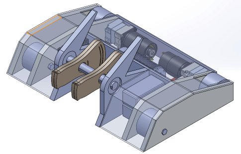
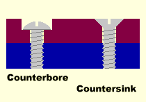 Q: My third question [You and I count differently!] is about bolts/tapping plates connection. I currently have 1/16", 1/8", 1/4" and 1/2" aluminum to work with for plating. I also have M3, M4, M5, M6 bolts to work with. In my design I wanted to countersink my bolts so that I didn't leave an exposed bolt to be sheared off by the enemy weapon. But my main confusion is the best combination of these. Because say if we use a 1/2" plate, the bigger the bore a tap we make, the less wall material we leave to support the bolt.


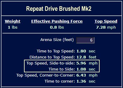
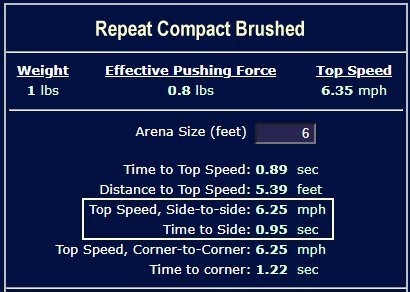
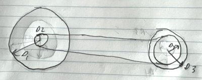 A: Mark J.
The smaller wheel requires the smaller pulley. When driven by the larger pulley it will spin faster to 'keep up' with the larger wheel.
A: Mark J.
The smaller wheel requires the smaller pulley. When driven by the larger pulley it will spin faster to 'keep up' with the larger wheel.


 Q: This isn't an 'Ask', more so an 'Answer'. I've seen a few people come here to ask about building shufflebots, so I decided to make a GIF showing how they work. I used Opentoonz, a free animation software. I hope you like it!
 Q: Hey there! I am a relatively new combat robotics builder that has just recently completed my first beetleweight robot named 'Faraday'. It's my own take and attempt at the design concept of "Monkfish", a very successful beetle which features a horizontal undercutter along with a shuffler drive mechanism.


 Q: Hi, Its ghost with backyard bots again.
 Q: Are "double hinged" wedgelets more effective than regular ones? I've seen them used on 'RotatoR', but (just from personal observation) it doesn't seem to out-wedge opponents any more than other bots with forks.


 A: Mark J. I don't have anything specifically from Team Drillzilla, but there are multiple shufflebot resources on the web.
 A: Mark J. UHMW polyethylene takes wood screw threads well and loses very little strength if you take care when re-inserting the screws and don't over-tighten. Assuming that you drilled a proper pilot hole (~3/32") into the UHMW for the #6 wood screws and the 1/2" length is long enough to bite well into the plastic support you can reset the screws dozens of times and the mounting will remain strong.
 With my basic knowledge of mechanics I guessed option 2 would be better for increased force to the lead screw, because the radius of the sprocket attached to the lead screw would provide a moment to the lead screw, thereby giving a mechanical advantage. However the other party said that the motor having to spin the first sprocket would be disadvantageous and would cancel out any gain the second sprocket gave to the lead screw, thereby transmitting the same force overall. Who is right?

 Q: Hey Mark: You may remember me as the kid with the following cheerleader-button-deserving designs:
 Many insect-class builders use simple wood screws for this type of connection into soft plastic with good results -- but there are special 'thread forming' screws made with widely spaced and deep threads that are designed to hold in thermoplastics; search for "Plastite" screws. Pick a suitably long screw, drill the correct diameter pilot hole, and sink 'em in.
 If the part will be removed frequently you can cross-drill the chassis and install barrel nuts with machine screws. This type of fastening is commonly used in assemble-it-yourself furniture. They're more work than simple screws and you may have trouble finding small barrel nuts, but the screws will break before they pull thru.
 Although it has fallen a bit out of favor you can certainly use FingerTech Nutstrip. It adds a bit of weight and takes up a little room, but it holds well.
 Q: How are betas ugly and mullet armor supposed to work? every time they use them they lose.
  Q: Hello. I am building a rotating flipper where a fork goes over and under the opposing robot and spins to flip them. There is an example photo attached.
 Regarding 'Orienting a Fork', I believe I might be able to offer some first-hand input to this sort of design - I ran 'Grapple Turnover' (image at right) at Beetleweight over in the UK - it's not a super competitive sort of design, unfortunately, but it is fun to try and use. As you point out, blipping the weapon to the right position for an attack is a pain, but it's a little less of a pain than you'd imagine, particularly if Lexington intends on running a single point of contact at the front - single point of contact is pretty much the ideal, and it's where I'm moving to with the Grapple Turnover redesign.
 OK! Both the brushed and brushless versions of the Tentacle Drivetrain Calculator now have a 'Magnet Downforce' field highlighted with yellow text right under the
  The previously reported bug in passing magnet downforce data to the Acceleration Calculator has been squashed. The calculator is now correctly showing the improved acceleration from reduced wheelspin with magnet downforce.
  Q: Hello! I had a question about wedge mounting and geometry. I designed and competed with a featherweight holonomic hammer bot similar to 'Shatter!' in a recent competition and used a 45 degree bent titanium wedge on hinged brackets to combat horizontal spinners. I'm currently doing a redesign which includes a slanted front and was wondering if we should change how it is mounted. I can continue to mount it on hinged pins, shock mount it to the front with rubber tampers and countersunk bolts, or bolt it directly to the frame like on Blue.

 A: Mark J. Since you didn't tell me anything about your current wedge I'm unable to suggest specific improvements. In general, playing the 'lowest wedge' game can be frustrating.
 Q: How can I minimize the "torque reaction" created by my robot? I have a 2 wheel wedge and during acceleration, the front end always lifts up. I have a lot of my components relatively close to the drive axles because I thought I would help with pushing power; should I try moving them further forward? [Chico, California]
 Q: Salutations!
 Q: Hello, it's the builder of Gaston again [see six posts down the page]. I took your advice, and created a completely new design for Gaston. I moved the center of mass closer to the wheels, and switched the motors to these: ServoCity 970 RPM Economy Gear Motor
According to the team tentacle calculator, my 'bot's top speed will now be about 4mph. However, according to the results from the calculator, I don't even need a 0.1 amp hours for a 3 minute match! Did I do something wrong, or are these motors just that powerful? Also, I attached a new rendering of Gaston (don't worry, the wheels and shafts are a work in progress, the body is the main focus). What are your thoughts on the new chassis shape and the motors? Thanks!
Q: Hello, it's the builder of Gaston again [see six posts down the page]. I took your advice, and created a completely new design for Gaston. I moved the center of mass closer to the wheels, and switched the motors to these: ServoCity 970 RPM Economy Gear Motor
According to the team tentacle calculator, my 'bot's top speed will now be about 4mph. However, according to the results from the calculator, I don't even need a 0.1 amp hours for a 3 minute match! Did I do something wrong, or are these motors just that powerful? Also, I attached a new rendering of Gaston (don't worry, the wheels and shafts are a work in progress, the body is the main focus). What are your thoughts on the new chassis shape and the motors? Thanks!

 A: Mark J. They left out a few arrows.

 Centrifugal forces in a turning 'bot cause the mass-centers ahead of and behind the center of rotation to seek a common plane of rotation parallel to the rotational plane of the robot. In your 'bot this effect applies an upward force on the weapon-end in an attempt to achieve that common rotation plane. If this force exceeds the weight on the weapon skid, the weapon will pivot upward a bit and the weapon axis will deflect rearward. Gyro forces may then lift one side of the bot and aerial gymnastics commence.
 In my similarly designed 3lb bot I have a BLHeli_32 ESC that I have recently adjusted the settings to limit the disk acceleration in hopes of combating these issues, but I have not had much chance to test it yet. My older 1lb ESC does not have this acceleration damping capability, so it looks like I may need to look into upgrading to a newer ESC to slow down the spin-up on my 1lb as well.
 Q: Hey Mark, I've been working on an idea on and off in my free time for a new robot and wanted some input on a few specific pieces. The idea is a 1lb [vertical] thwackbot/spinner in similar style to 'Starchild'. I think it's worth noting I don't have access to any fancy tools - most of this is being done with screwdrivers, wrenches, hammers, hacksaws, etc
tools pretty much every average Joe Schmoe has access to.
Q: Hey Mark, I've been working on an idea on and off in my free time for a new robot and wanted some input on a few specific pieces. The idea is a 1lb [vertical] thwackbot/spinner in similar style to 'Starchild'. I think it's worth noting I don't have access to any fancy tools - most of this is being done with screwdrivers, wrenches, hammers, hacksaws, etc
tools pretty much every average Joe Schmoe has access to.
 A: Mark J. What you are proposing for your weapon is not a hubmotor. A hubmotor is embedded inside the device it is powering, like the vertical spinner weapon on 'Algos', or the simple Fingertech clamping drum weapon. Your design hangs a large spinning mass off the far end of the weapon motor, where a weapon impact will act with a large lever advantage on the bearing tube support at the base of the motor. This effectively guarantees structural failure of the weapon motor. Reconsider
 3) Lastly, here's a shot of the entire robot idea I laid out a few days ago. My worry is that the weapon system (109g, ~55mm diameter) is way too big and heavy to swing around effectively, and would instead act more like a vertical spinner and less like a thwackbot as intended. This also becomes an issue with the larger weapon setups (up to 233g and ~99mm diameter) I had intended to purchase to change to depending on the opponent (namely wedges so I don't have to use as much armor). I know that weight, weight distribution, and the motor torque all play an important role in the overall efficiency of an overhead thwackbot (as talked about in the Riobotz Combat Tutorial), and when watching videos of Starchild it seems like their weapon is pretty lightweight. I had considered bumping up the weight to a beetle given the electronics would work fine in a 3lb robot (just need a better battery and maybe a different weapon ESC especially if I bump it up from 3s to 4s), but I wasn't sure if this would combat the issues I'd have with the 1lb version... or if maybe I should try something else out with the 1lb version, like a standard vertical spinner?
 Q: I'm learning how to design bots and I'm starting out with the RioBotz Combat Robot tutorial from 2009. I'm guessing the design fundamentals and calculations will all hold up, but are the sections about electronics, motors, materials, batteries and such still relevant? If not, are there any good comprehensive resources on currently used components? [Social Media]

 Q: Looking at robots like 'Sawblaze' and 'Skorpios', how are they controlling the end points of their arm movement? I know they aren't using servos at this scale, and I don't think they are simply using hard stops and letting the motor stall. Do they use limit switches? Are they building their own servo control system into their larger mechanism? Thanks.
 Q: Hey, Mark! 2020 has been a rough year for all of us, so I'm hoping to bring something to my local competition this year. I'd like to bring something entertaining or unique to the table, but I keep running into the same problem: I can't decide on what to build, and I can't bring myself to completing any of the projects I've started even when I get the CADs close to complete.

 Combat robot builders typically start at MUCH lower weight classes to gain experience where their mistakes cost a whole lot less money. Heavyweights are 'the big league' -- showing up with your first robot to compete against well-financed and experienced builders is likely to send you back home with a basket of scrap.
 If I had one shot to win Norwalk I certainly wouldn't show up with an unseasoned mainstream spinner. I think something like a wider and more durable 'Krave Monster' dustpan (video) with a clamp and anti-backout lip might work. Go with fiberous ablative/entangling materials for the side and back walls of the pan to give the spinners something to chew on and hope that you don't draw 'Smeeeeeeeee'. Flamethrower Optional. If it doesn't win it would at least be fun.
 The concept of 'Krave Monster' is to grab robots and carry them to an arena 'pit' where they are released. A passive lip would hinder the release, so the initial design incorporated a servo to raise and lower the lip. Later versions of the 'bot removed the anti-backout lip entirely, but I think the concept has ample merit to consider in other situations.
 Bottom Line: A small toe adjustment on a differential steer robot will be lost in the huge slip angles imparted by the differential steering process. If you're interested in improved turning response in differential steered robots, see our Beginners Guide to Combat Robot Gyros.


 Q: What components do I need to consider if I want to connect a motor, a drive belt and a wheel. [Brighton, England]
 Q: Hi, i have 2 questions to ask
 A: You've given me very little information about your robot. You mention that it is 'small', has two motors, is 4-wheel drive, and requires 0.2 Nm (28 in-oz) of torque per wheel. That is not enough information to answer to your questions. The Hamburger is Bad.
 Q: i have to produce a combat fighting robot and my part is weapons electrical, and therefore what calculations do i make as my robot consists of two axes on the sides of the robot and a spinner blade in the middle [Edgware, England]
 We have calculated that we can use Propdrive 2836 2200kv outrunners with 20:1 gearboxes for our drivetrain, and the same motor with a 2:1 belt drive for the spinner. Since all 4 motors are the same, could we run them off one of the 4 in 1 quadcopter ESCs? (With the requisite firmware flashing, control board, etc.) Something like this. These ESCs are designed for quadcopter use where there is plenty of airflow, but we figure we can manage heat by mounting it to our aluminum chassis with a thermal pad.


 Q: I know what you're talking about in the answer with the defensive wedges on the support horns, but do you have any advice on how to attach them to the robot? I could just use 1 NutStrip and screw the wedge onto the bot, but I am skeptical that only a few screws won't fall off or shear.
 Q: How long do I have to wait for blue Loctite to dry before it gets good locking strength? When I tighten down a nut and then put a drop on the exposed threads it stays wet for a long time. [Salt Lake City, Utah]
 A: Mark J. A combat robot is a complex assembly of components and systems that all have to work together to be successful. Forcing new builders to add an active weapon (lifter, flipper, spinner, crusher...) is a disservice to both new builders and the combat robot community. It creates a barrier to participation that practically guarantees frustration and failure for novice builders.
 Q: Maybe it's just my imagination, but Hypno-Disc was always interesting to me in that it when it turned, it would turn about a point that was closer to the front of the robot rather than the centre and sling the back out. How did it manage this? Was it just weight distribution that caused this effect or was it something about the wheels? [Ashford, England]
 A: Mark J. You're not giving me much to go on, Florida. The snail cam is a reasonable mechanism to compress and release spring force, and it is fairly simple to calculate the energy stored in the compressed spring, but translating stored energy into 'impact force' is complex, requires many assumptions, and varies with the characteristics of the object being impacted.
 From a standing start your robot will accelerate more and more slowly as the speed climbs and torque diminishes. With greater speed comes greater friction and aero drag. When the total drag climbs to the point that it matches the available torque from your drivetrain, acceleration stops: you're at top speed.


 Q: A robot that has fascinated me and a design I can't recall being repeated was that of 'LOLCano V' (as it's called on BuildersDB). One thing that isn't really explained, however, is how exactly they managed to get both the drivetrain and the weapon to move on the same axle. What are some ways to accomplish this, and what am I missing with these designs that I'm most likely overlooking?
 In a more common FBDS design layout as used by 'Daffodil' (archived build report):
 A: Mark J. Many designs qualify as a 'clamping' collar, and some are better than others for both torque transmission and axial shock. Holding 'well enough' depends on the specific application, information you have elected to withhold. I can comment that clamping collars are generally preferable to set screw collars.
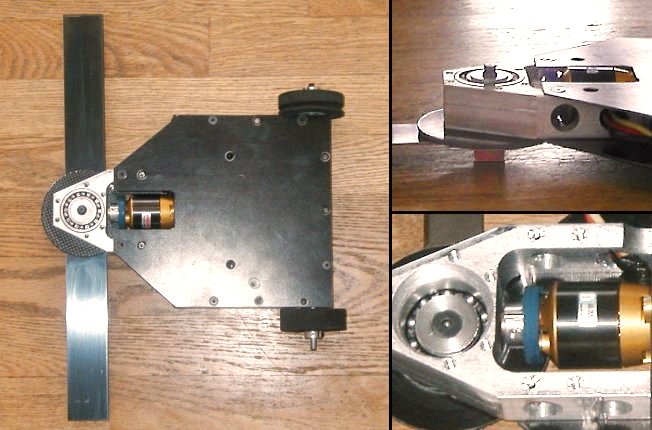
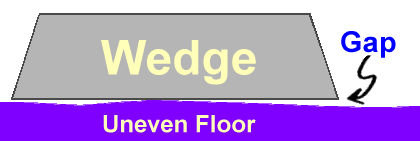
 Q: is it a good idea to put a titanium original sin style attachment on a d2 kit to stop wheels being shredded? [Fairfax, Virginia]

 A: Mark J. Scroll down four posts to Columbus' question about active weapons at BattleBots. Another 'Tombstone' clone wouldn't get your design accepted for BattleBots, but hanging a bar spinner or two off the side of a 'bot got these teams 'in'. Valid combat reasons? You can circle your opponent with a weapon pointed at them and veer inward to 'strafe'.
 Q: I am unconvinced that 'sidewinder' wasn't the result of a horrific teleportation accident involving 'last rites' and 'original sin'.
  A: Mark J. A double horizontal ring bristlebot... As they say on the forums, "it won't not work." 'Lurch' kinda works (video).


 Q: Just a quick, somewhat random question: I was watching the footage of 'Wrecks' in [ABC BattleBots] Seasons 1 and 2, and I've noticed that season 1 'Wrecks' seems to control a lot better than season 2 'Wrecks'. Closer investigation reveals that the original 'Wrecks' was seemingly lower to the floor and although its leg had limited motion (in contrast to season 2 Wrecks's leg, which could rotate 360 degrees), it allowed season 1 'Wrecks' to move easier at the cost of having a harder time self-righting.
 "There is such a thing as too much gyroscopic force for a precession walker. The maximum pivot speed is expressed as (force of gravity) × (distance between centre of gravity and the point of contact with the ground) ÷ (angular momentum of the disk). Which means if you spin the disk twice as fast you (very counter-intuitively) actually cause the robot to pivot half as fast. You can see this in spinning tops because as they slow down, the wobble speed increases.
 A: Mark J. The Tentacle Drivetrain Calculator is a tremendously useful combat robot design tool, but you need to understand what it's actually telling you about the drive train design. Among other things, the calculator estimates the amount of torque needed to 'break traction' and spin the drive wheels of the robot based upon the weight pressing down on the wheels. If the drive train cannot provide at least that much torque the drive motors may 'stall' under heavy pushing loads, which will both reduce pushing power and risk damage to the motors. The calculator will warn you of this condition.
 There once were a great many combat robot build logs out on the 'net. A new builder could learn from the experiences of other builders and find answers to questions they didn't even know they had. Now there are very few builders that even maintain websites, and fewer still who are willing to share their build secrets.
 Q: Hi Mark. I had a design that I thought was a bit outlandish and would be a waste of time, but the cheerleader button told me it was a great idea and to go for it.
 A: Mark J.
You've told me absolutely nothing about your robot or your weapon, but you want me to recommend motors. It this the type of engineering they teach at ITT Kanpur?
A: Mark J.
You've told me absolutely nothing about your robot or your weapon, but you want me to recommend motors. It this the type of engineering they teach at ITT Kanpur?


 A: Mark J. I'm pleased to find that you're continuing development of your swerve drive, Niedersachsen. It's more than a bit too complex for my personal taste, but it will certainly be an accomplishment to get it operational.


 Q: first,as you can see a wedge. & i plan for a motor powered lifter in future. i've hit my first event & had issues with keeping all wheels attached to the ground. Its a six wheel small compact robot which i think i need to improve a lot,specially keeping all in a same level. & I'm struggling with it so far.
 Q: as my design is pretty compact & we have size limitations out there.. i have at most 11 inches for all three wheels. so,do you think it'd be fast enough with 3.5 inch wheels.??
 Q: Hi Mark.
 Q: I used the on-line robot drive motor sizing tool at robotshop.com to help me pick drive motors and batteries for my robot, but the numbers it's giving seem very small. Can I really power my 60kg combat wedge robot with a pair of 175 watt motors geared for 7 mph and draw only 15 amps total at 24 volts? [Nepal via Facebook]
 1) Is there a way to determine the gearing ratio on a robot with a chain or belt-driven drive with front and rear wheels of different sizes? For instance, the rear wheels are 3", and the front wheels are 4". The rear has, say, a 1.75" sprocket, the motor itself has a 2" sprocket, and the front has a 3" sprocket. These aren't real numbers, they're just random numbers to be used as an example.
 The flaw lay in a very poor hardware choice. The output shafts for my drive gearboxes have a 3mm hole. I designed wheel hubs to slip over the shaft and used an M3 alloy bolt to lock the shafts to the hubs. Bad idea. About a minute into each fight, both bolts sheared and turned my bot into a very expensive paper weight. I didn't take any major hits, and I believe that the bolts sheared solely from the torque of the motors turning the wheels back and forth.
 Q: So it sounds like a hardened pin isn't going to be my simple solution. I don't know of any other offset gearboxes that I could switch to and fit inside the robot in the same way. I'm trying to avoid redesigning the whole bot and have a couple ideas. I could try to modify the gearboxes and install a larger shaft, but I'm sure that is easier said than done. My other idea seems a little more appealing (for the moment).
 Q: Are Auto reset breakers a good idea for Amp spikes In a combat robot? [Hagerstown, Maryland]
 Q: So I was thinking to start building an antweight for Massdestruction. I was thinking a overhead grappler (not a crusher) and a wedge. This is gonna be my first combat robot and I'm not even sure she I'm gonna build it. Is this a good one for beginners? Thanks!
  Q: My horizontal spinner has a big reaction on weapon startup that rotates the robot opposite to the weapon direction. I'd like to activate a high-traction 'foot' that presses down against the arena floor to brace the robot against rotation when the weapon is under high spinup load. Is there a sensor that will detect high current flow to the brushless weapon motor that I can use to activate the foot? [The Forums]
 1) 'Double Dutch' is quite an unusual machine, both in shape and its idea of using two counter rotating blades as weaponry. My first question about Double Dutch is simply this: does using two counter rotating blades generate more force than, say, using two blades rotating in the same direction? I'd assume that the answer would be no, but hey: that's why I came to ask you!
 4) What exact purpose do the curved bits of 'Bronco' serve? I'd assume they're built to keep vertical drums at bay, but if they are, aren't there simpler ways to deflect vertical drums?
 Q: What is the current best Crusher in the world? [London, England]
 Q: Is it ok to have a tip clearance of 1/16" - 1/8" off the ground for a vertical spinner, or is that too close for comfort? [New South Wales, Australia]
 A: Mark J. Are you using the washer to locate a hub that's free to float inward toward the gearbox? If so your nylon washer is likely OK, but I'm a little worried about arena swarf getting embedded in/under the soft washer and causing friction/binding.

 I've noticed that there are usually two kinds of full-body spinners: those that are low and flat, like Capt Shrederator, and those that are big and square-ish, like Megabyte and Gigabyte. What pros and cons come with each of those designs or, more specifically, those shapes?
 Q: Just curious to know, which system is generally lighter: a hydraulic system or a pneumatic system? [Champaign, Illinois]
 Q: Hi Mark, do you have any suggestions or information sources on recommended design principles for wheel hubs, not dissimilar to what you'd find in the Riobotz manual? I'm thinking of casting custom wheels. [Fremont, California]

 A: Mark J. When you see a Hal Rucker robot with some unusual component that you don't understand, the correct question is not "Why is he doing that?" The correct question is 'Why am I not doing that?"
 A: Mark J. That's easy...
 Q: So you said that simple robots win but I was wondering how Tazbot did so well even though he was kinda complicated. Ty! [Lynn, Massachusetts]
 Q: So I saw overdrive S1 had some technology in it's wheels. What does this do? Thanks! [M]

 Q: So you said simple robots win. What are some examples of simple robots that did well? Heres one I like... [Lynn, Massachusetts]
 Why not as good? Because simple robots are tougher competition than complex showboat 'bots. Which heavyweight robot has the best record against 'Last Rites'? That would be an even simpler robot: the fearsome wedgebot 'Original Sin'.
 Q: Hello! I'd love to know what motor(s) did Paul's bot Brutality from Aptyx Designs used, and how was it configured? [New York]
 A: Given the components you've selected and the gear ratios you're looking at I'm gonna guess that you're coming at this from an R/C car background. The requirements of a combat robot are a great deal different than R/C cars.
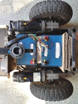 I am in the process of playing with a design for an autonomous agricultural robot, and am attempting to use a mobility scooter chassis as the platform to base a prototype on.
 2) I've noticed that some robots that use a connected drivetrain are connected in the center, with one sprocket leading to the right side of one wheel and one sprocket leading to the left side of the other (Examples I could come up with off the top of my head include Deathcap (Beetleweight) and Otis (Featherweight), but there are many more). Why not have one chain connected on one side of both wheels? What advantages does one receive from making their drive chain in the way explained above?
 8) Lastly, I linked a picture of a flipper idea I had. I wanted to create something that was similar to designs in the US, but not as stiff, and the UK, but not as free-flowing and reliant on cables to keep it from breaking. Is this a good idea in terms of a good mechanism? What would need to be changed or are things of potential concern?
 A: Mark J. You've failed to mention what flooring you will have in your "normal arena". It matters. What I would recommend for a steel floor would be different from a painted wood surface, which would be different from a dusty concrete floor. My choice also varies with the size of the wheel you want to use. Traction is also highly dependent on the percentage of your robot's weight that is supported by your driven wheels.

 Q: The description for 'Foiled!' says "Increase effective weight to make wedges useless". What does this mean, and how does it make wedges useless? [Baltimore, Maryland]
 Q: Hi Aaron, I have recently been building a beetleweight and I am curious as to what you think of the structure of my robot. I modeled everything up in plywood so I won't mess up when I make it out of UHMW. Can you take a quick look at my robot and see if there are any major problems I have overlooked.
 The body of the robot looks to be overly large given the equipment it will contain. A smaller box will weigh less, and you can use the weight for a thicker wedge and maybe a little wheel armor.
 [Wheel location] is a problem I was worried about and plan on fixing when I build my real robot. I'm actually a bit cramped on space surprisingly so that's why the wheels are in the very back. I think I can still shrink all dimensions by at least 1/4 inch.
 The experts in fan-downforce are the builders of line-follower and maze-runner robots. The photo at right shows the underside of a line-following 'bot with fan downforce. There is a post farther down in this archive with some links to useful info -- search for 'suckbot'.
 Q: I've seen many insect weight builders using the Fingertech pulleys and belts to power weapons and drive systems. How do those builders attach said pulley onto a weapon. I'm a bit confused about the documentation of those pulleys on how they are mounted. Could you show me examples or tell me the best way to mount them. Thanks! [Columbia, Tennessee]

 Q: I'm making a 1 lb robot [sketch at right]. What is the best position for my wheels? And why? [Newark, Ohio]
 Q: I am looking to completely remove everything behind the wheels to cut weight, how will it affect my driving ability?
 Q: Hey! Normally I wouldn't give a question right after I just sent you a few, but I forgot to ask this one earlier: Suppose I was trying to make a horizontal crusher like 'Tough as Nails' but as a beetleweight. How exactly should I go about building the pneumatic system? Beetles can't have hydraulic systems at their size, right? The idea I had in mind wouldn't even have to crush the robot: it should just be able to clamp them. I'd like to keep the design close to the original as well. [Champaign, Illinois]
 1) Is there a type of wedge or plow shape that's good at deflecting both horizontal and vertical spinner attacks?
 A: Mark J. I can post formulas and diagrams about gyroscopic forces that go on for pages, and in fact I have: search the Ask Aaron 'Robot Design' and 'Robot Weapons' archives for 'gyroscopic'. If you really want to understand gyro forces I strongly recommend that you purchase a small toy gyroscope and play around with it.
 Design 1 A taller and relatively short drum with the outriggers hosting the motors. These outriggers would have wheels on them to help steering
 Q: Hi Mark. I was doing some research on ways to prevent bolts and screws from loosening during vibration or stress. Two common solutions I am aware of include nylon insert bolts/nuts and thread-locker. Generally speaking, is one method better than the other? Also can both be used simultaneously or will the thread-locker mess up the nylon? In my specific instance I am building a weapon arm with through holes at the ends that holds 2 S7 tool steel impactors approx. 1" by 1 3/8" which will be tapped and have bolts run into them. Many Thanks... [Pittsburgh]
A: Mark J. There is a good discussion of the benefits and drawbacks to threadlocker vs. nylon inserts at eng-tips.com. Briefly, threadlocker holds better than nylon IF properly applied to clean threads and allowed to fully set, while nylon inserts are foolproof and immediately useable. If there is a chance that I'll need to remove the bolt and replace it between matches I'll use nylon, otherwise a carefully applied threadlocker is my choice. Don't use both -- most threadlocker compounds don't mix with plastics.
Q: Hi Mark. I was doing some research on ways to prevent bolts and screws from loosening during vibration or stress. Two common solutions I am aware of include nylon insert bolts/nuts and thread-locker. Generally speaking, is one method better than the other? Also can both be used simultaneously or will the thread-locker mess up the nylon? In my specific instance I am building a weapon arm with through holes at the ends that holds 2 S7 tool steel impactors approx. 1" by 1 3/8" which will be tapped and have bolts run into them. Many Thanks... [Pittsburgh]
A: Mark J. There is a good discussion of the benefits and drawbacks to threadlocker vs. nylon inserts at eng-tips.com. Briefly, threadlocker holds better than nylon IF properly applied to clean threads and allowed to fully set, while nylon inserts are foolproof and immediately useable. If there is a chance that I'll need to remove the bolt and replace it between matches I'll use nylon, otherwise a carefully applied threadlocker is my choice. Don't use both -- most threadlocker compounds don't mix with plastics.
 A: Mark J. The RioBotz Combat Tutorial was written in Portuguese and loses a bit in translation. The descriptions are also a bit brief in places. To be fair, 'Ask Aaron' probably doesn't translate well into Portuguese.
 Shock absorption is a too-frequently overlooked aspect of armor mounting. In combat robotics, layered armor has proven inferior to single-piece armor with rubber shock mounts. The photos at right show the front armor pods and rubber shock mounts used on BattleBots competitor 'Overhaul'. Properly sized mounts will be quite firm -- they will barely flex under the best pressure you can exert on the panel by hand.
 A: Mark J. We all hope to make amazing machines, but 'first combat robot' and 'drum spinner' do not go together. You may be surprised to learn what weapon types are most successful. See also this post farther down the page.

 Q: What is your least favorite bot design? Okay, got it?
 Q: Hello, I have 2 questions. Bot info:

 A: Mark J. It's a common error for new builders to assume that a given combat robot performs well largely because of the design. The robots you mention are successful for many reasons. They are:
 1a) When it comes to face spinners, what is the biggest do and the biggest don't for them (in terms of building one)?
 2) Would a flipper that pushes against the ground like Polar Vortex's original version be a good idea? What would the pros and cons of a design like that be?
 4) In your opinion, would a walkerbot like Wrecks work with a massive drum spinner?
 10a) How, against all odds, was Pussycat so successful?
 11) Why do Splatter and Whiplash have their spinners on their lifting arms, what point do they serve, and how effective are they really?
 12a) If a robot had a pair of [cambered] wheels and a drum spinner, what problem(s) would the builder have to face?
 5) I once heard of having a tapered drum on a robot, one where the sides would be angled and have teeth. It's odd but different. You thoughts or concerns?
 The 'Cone Army' almost got on BattleBots. Greg wanted it, ABC didn't. It was supposed to be the successor to 'VLC' which fought at Motorama 2015 and died a warriors death at the hands of 'Pitter Patter' and 'Uberclocker' (video). The tagline in the application was, "Tombstone can't beat 37 cones."
 14) 'Huge': Do you think a concept like 'Huge' from Motorama would work in the big leagues if it was adjusted significantly? Also, what advantages/disadvantages does a design like Huge's have?
 A: Mark J. There isn't a simple answer to your question. Successful combat robots span a broad range of speed and acceleration parameters due to variation in weaponry, arena size, attack strategy, and driver preference.
 Q: Hello! I was watching some fights from India (I know: scary, right?) and I saw this not so little guy and was intrigued by its design. I'm intrigued so much by it that I would really like to make my next robot look similar (gotta finish my first robot, well, first).
 Fourth, and this one is a bit crazy, but what if the robot was similar in design to Infernal Contraption, where there are drive pods rather than actual wheels? The main section would keep the design like Angar, but it would be able to rotate and flop around like Infernal Contraption does? I can say at least an asymmetrical design would make it easier to tell which part is the robot's bottom.
 If you're very tight on weight allowance you actually can use Zip ties, but you must use them correctly! The usual Zip tie (cable tie) mounting simply drills a couple of holes in the mounting material, loops the tie thru it, and snugs it down. This relies in the tie to restrict lateral movement (shear forces) as well as hold the object down to the surface (tension forces). If you were to bolt or epoxy narrow strips of CF to the base material that snugly kept the ESC from sliding port/starboard and fore/aft, a cable tie holding the ESC in place would experience only tensile loading, for which they are rated. The 4.8 mm wide ties are rated around 30 pounds tensile, so a pair will survive a minimum 100 G shock loading when holding a 90 gram object.
 A: Mark J. 'Bombshell' was designed to accept multiple modules in the central weapon bay. The outer drive pods have the drive wheels on one end set in conventional position toward the outside edge of the 'bot, while the other end has the drive wheels set well inboard -- actually encroaching on the weapon bay. This offers advantages depending on the weapon module used.
 A: Mark J. Since we're talking about a design concept unrelated to a particular event I think we can avoid the mystery and let the readers know that we're discussing 'Razer'.
 A: Mark J. Spinner defense is best accomplished with perfectly smooth, hard, gently curved surfaces on the outside of the robot. No sharp edges to give spinners a place to 'bite', no soft materials for sharp spinner teeth to dig into -- so absolutely no wood blocks!

 Q: Hi Mark, I am the Indian guy who asked the question. I think you are still under the wrong impression that arena used in our competitions are unsafe. Now most of the places in India use polycarbonate sheet walls for the arena. The good teams don't participate in the competitions whose arena are not safe for fighting due to obvious safety reasons. The sheets in the image are 10mm thick.

 A: Mark J. Hello, Sheffield. Thank you for your kind holiday wishes.
 A: Mark J. I've vowed to avoid calculus in the answers I give here at 'Ask Aaron'. I'm severely tempted to break that vow for this question given that the answer involves a system of non-linear equations, but I think I can provide an approximation that's plenty close enough for combat robot purposes while leaving a trail of crumbs for the 'Sons of Newton' to follow if they so desire.


 A: Mark J. A couple things for you to consider:
 A: Mark J. There are good reasons why you can't find so large a pulley for so small a shaft-- it's poor engineering practice. You haven't told me what you're building, but I can't think of an application where this would be a good idea. I'd feel much better about this if you'd share your design with me; I might be able to head off a problem.
 Now, gear reduction. If you were an experienced machinist you wouldn't need to ask me how to make a gearbox, so we'd best keep this simple. Take a look at a previous post in this archive on two-stage chain reduction drivetrains. 'Run Away' used a two-stage chain and sprocket drive to give a 12:1 reduction ratio, so it's certainly do-able without precision machining or great expense.
 A: Mark J. You have to dive in someplace, so let's go...
 Q: if i want to join 2 side of the chassis with screws, if i tap them both seperately, will the thread match? like will the 2 pieces be straight? [Quebec, Canada]
 A: No. Every component should be individually anchored to the chassis:
 Q: is it me or in the first season of battlebots on abc, stinger can have the lifter of sewer snake on the front, or swap it to one who looks more like evil plunger? i saw the tested video, but im still unsure [Quebec, Canada]
 Q: I've got a hockey robot (basically, a 12 pound combat robot without an active weapon) that I threw together in a weekend for an upcoming event later this month, but it turned out to be over six pounds underweight. Unfortunately, I can't really do much to the design of the robot without starting from scratch, so do you have any possible suggestions? I know this is a vague question but I'm out of ideas. [North Carolina]
 Q: I designed an antweight wedge on Sketchup and I put the receiver, the ESC, the battery, and the motor inside of the frame. I wanna know how much room should I keep for the wire? [Quebec, Canada]

 Q: Dear Aaron, I'm trying to build an 30lb, middle weight, or any weight that is not a heavy weight combat robot which looks very close to the robot in this image (not mine) and I would add a Biohazard type CO2 type flipper. Can you tell me the complete parts list with controllers and all that please? [Team Combat Robotics Malaysia - Selangor, Malaysia]
 I used to wear a cowboy hat with a cartoonish foam plastic chicken head, wings, and tail sticking out from the crown. One day a man once took out a camera and motioned to me to turn a bit so he could get his shot.
 A: Mark J. Due to concerns for the safety of combat robot builders and spectators, I regret that I am unable to answer combat robot questions from the Indian subcontinent.
Click here.
A: Mark J. Due to concerns for the safety of combat robot builders and spectators, I regret that I am unable to answer combat robot questions from the Indian subcontinent.
Click here.
 The mega Q&A session about the design of the Texas Bar Spinner grew so large that I moved it to its own page: Ask Aaron: Texas Bar Spinner. I think the discussion is over -- for now. See how it came out!

 Q: What is your opinion on the use of nutplates for attaching armor to structural members? Assume attachment is to a thin flange off the side of the structural member rather than drilling and tapping a hole directly in the structure. [Charlotte, North Carolina]
 Q: How come we don't see more robots using two wheels on each hub like 'Sewer Snake?' Looks like it works pretty well for them. [Andover, Massachusetts]
 Q: Hey mark,
 Back to the 'how': It's easier to see what's happening in a smaller robot. Take a look at this video of Team Misfit's antweight 'Gyrobot'. The spinning weapon is mounted to a servo that tilts the weapon to the left and right relative to the robot chassis.
 Q: How do you do, what tools do you use to make and repair robots? [Jiangsu, China]
 Q: Hello I am working with a combat robotics team in California, and we are planning on building a 4-bar flipper robot. We were very happy to see that you were hosting [the T.i. Combat Robotics 4-Bar Simulator software] so that we can still download it. I was wondering, however, would it be possible to obtain the source code for the program, so that we can remake it to add functionality and make it run faster? [Beverly Hills, CA]
 Q: Hello,Mark. What made horizontal gripping/crushing weapons like 'Tough As Nails' and 'Kan-Opener' still being rather competitive even after the TV era? They can easily be the targets for flippers, but they still could win some fights. [Chinese Forum]
 A: Mark J. A 'strategy' is the goal you want to accomplish; in this case that would be successfully using a wedge against a robot with anti-wedge skids. A 'tactic' is the method you employ to accomplish that goal. I think you're looking for a tactic rather than a strategy, and there are several available:

 Q: I would like to create a robot which has pincers that raise the robot off the ground (a bit like Big Nipper, but with only the pincers lifting the opponent). I would like to find out how the pincers can work and lift on the spot. I would like two pairs, one above the other, and a light, fast 6 wheel drive with remote ardunio programmed. Do you have any advice? [London, United Kingdom]
 Q: What do you think of Bite Force? DO you think its magnet is useful? [Guangdong, China]


 Second problem: your FBS design is poorly suited to match-up against a vertical spinner. Head-to-head, the large diameter vertical flywheel will make contact with your shell well before your undercutter blades can find a target. Outlook very poor.
 A: Mark J. Glad to hear you find my answers helpful. I understand that this is a school project and that your resources are limited. Let's see what we can do.
 Scoop: Not PVC! I'm sure those nasty vertical spinners you'll be fighting have hard and sharp steel teeth, and a plastic scoop is no match for that. The steel will dig in -- even with little bite -- and rip the plastic apart. You'll need to match the hardness of their teeth with your scoop. Steel is a good choice here. Make it as thick as your weight allowance permits. Spend some time looking around the tool section at a hardware store -- you may find something like the big curved chunk of steel that pictured beetleweight 'CoMotion' uses for its scoop.

 Q: hello aaron, please suggest some ways how to make a drivetrain with chain and sprockets or some links may be..
 Q: Sorry Sir but I want to correct the previous question about AC supply in competition. I'm pretty sure about the rules. We can use either AC or DC supply. We wanted to use AC so that we can save the cost of Batteries as will be using Hydraulic pistons for our weapons that are quite costly and we have to outsource it. We will be using simple on off switches for driving (Wired Control). What we have planned is to convert AC to DC and all the motors will be DC so I Want to specifications of motors like Horse Power, Torque and rpm for the same above conditions stated in previous question? and the type of drive(four wheel or two wheel)?The robot will be 70*50 cm size and maximum height can be 1m. We want to use a heavy rotor, so motor must be powerful.
 The Solenoid Control of Robot Weapon and Drive Motors FAQ has multiple posts and a discussion of alternatives to ESCs that will work for "system-wired or wireless" control systems.
 I've been reluctant to provide a circuit diagram for a wire controlled solenoid drive 'bot because I didn't want to encourage builders to use this control method. However, I've decided that it's necessary to clarify the control issue. The diagram at right shows the two solenoids and single remote switch needed to control the drive motor(s) on one side of a 'bot. As noted above, the control switch has a very low current requirement since it only activates the coils in the solenoids.

 Q: Hi. I have questions about calculating a drive train chain reduction ratio.
 Q: How much motor power does it take to move my 60 pound robot?
 Q: How much motor power does my robot need to push with 60 pounds of force?
 Q: How much motor power does my robot need to push a 60 pound object?
 Q: Hi Aaron, excuse my writing mistakes because I do not speak English but want to build the robot battle Ziggy. What materials do I need ?, How I can build it? [Ecuador]
 Q: hello mark,could you suggest me a motor to hit a badminton smash for robocon.Since we are starting from scrach we have poor knowledge about motors.hope you respond me positively. [India]
 A: Mark J. I'm not sure exactly what your question is.
 A: Mark J. Relying on a strategy of attacking a vulnerable exposed side is not terribly workable. It's a rather long path to maneuver around to the side of your opponent, and all they have to do to counter is pivot. You might get lucky against your first opponent, but your second opponent will be waiting for that move.
 Q: hey mark ... the fork tooth guy ..... Now , if I make a hinged wedge which is invertible .... and I bend the edges of the wedge downwards ( for preventing side attacks ) like woloop or original sin.... then when the bot gets upside down .. then the portion bent down will be upwards ... will that be a good wedge?
 Q: Hi..Mark..what is the dimensions,motors and details informarion of UnMaker bot.. [Maharashtra,India]
 For my robot i'm planning on using 2 motors driving 4 wheels with timing belts. These motors are originally designed for use on hydraulic power packs. The specs of the motor are 24v, 500W, 2800 rpm, Duty cycle: S2- 5min (I don't exactly know what this means but it was written on its spec sheet & I think it might be the 5min working duration), 2.6kg weight, 3.75Nm stall torque, 80A stall current, 4A no load current.
 Wedge drivers should have the ability to raise the front edge of the wedge a bit if the the arena requires it. A little grinding to bevel the leading edge will usually do the trick. Alternately, a few Teflon 'glides' can be attached to the sliding bottom edge to rise it just a bit.
 Q: Hi guys this is Aravind from India, im building a wedge robot for my battle events
 Q: how did andy sauro's "triton" work? [Havertown, Pennsylvania]
 Q: As I told you, I bought four BaneBots 256:1 gearmotors for locomotion in my 30 kilo robot. Since it is very slow I am planning to make an 18" wheel and make a dead wheel unit in that (see drawing). If I do this will I increase the speed? Is it reliable? [India]

 Q: Could you comment on Team Toad's new machine 'Polar Vortex'? I think using the entire body of the robot as a lifting weapon is clever,and it seems very successful as well. [Chinese Forum]
 A: Magnets have been tried on many robots over the years. Most commonly, permanent magnets have been used to increase traction and pushing power in arenas with steel floors. There have been many successful magnet-bots, most in the insect weight classes. A good example is beetleweight 'Wallop', which uses axially polarized magnets for wheels. Team Nightmare claims that 'Wallop' can drive upside-down on a steel surface or even straight up a steel wall.
 Q: how to wind belt drives on wheels of robot so that it does not slips? [Maharashtra, India]
 A: Mark J. I love mousetrap cars! You can get some good help on design at the Doc Fizzix Mousetrap Car site.
 Q: Hey, I am unable to [mount] my ampflow e 30-400 motor vertical on my base...those screw in the base of motor are [too] small to hold it...suggest some solution? [Tamil Nadu, India]

 You didn't mention the planned length of your 'Sewer Snake' style lifter, which is critical in the calculations. Longer lifter arms require greater gear reduction.
 Q: Dear aaron, I know that team whyachi has a robot called warrior SKF.Do you have any information about it? How its toothed spining ring powered the flipping arm? & can you please give me its tech specification about its drive, weapon &its design . [Mumbai, India]
 Q: I'm trying to do a replica of 'Sir Force-a-Lot' in Robot Arena 2, any info on what internals they used?
 Q: It seems that 'The Matador' type flippers often have self-right problem. Why dont US builders use the design of Robot Wars flippers?
 Q: Dear Aaron, I saw the [Combat Robot Hall of Fame] honorable mention winner 'Gyrobot', and I saw in a video that the entire blade complex can swivel, but I would like to know how that works. I am also guessing that this is one of those bots that only an experienced builder could build, but I was just curious. Thanks, New york
 Q: I like Snow Flake's design. It is simple and fairly effective. However it only achieved moderate sucess. Do you also like Snow Flake's design? What about it's design would you change to make it more effective?
 Think of rattler 1 the drum bot, or even fluffy for a 15 lb robot. My idea is kinda simple. On the sides of the drum built into the frame of the bot (not actually the drum) are two linear servos with small wedges built into them. they can be moved in and out during the fight, so that they can be positioned infront of the drum completely, making a wedge, a wedge that would have a wedge that you would have to go up to be hit by the drum (think the Brain from USF RIG), or they can be moved all the way back so that the drum has nothing in front of it like Rattler 1. If I pin someone on the wall with the wedges out, I can then spin up my drum with them T-boned on the wall with the extended wedges, and then I could retract the wedges while driving forwards, allowing for a huge hit with the drum that is spinning already at a (close to) top speed.
 A: People will argue, but from a practical standpoint - not really. 'New Cruelty' (8 wheels) and 'War Machine' (10 wheels) were both super-heavyweights that added on extra power by simply tacking on extra gearmotors and wheels. The solution was appealingly simple, but the extra wheels themselves did not provide any advantage.
 Omniwheels can typically be found in either 3 or 4 wheel configurations, while Mecanum wheels are most commonly found in 4 wheel designs. A motion diagram for a 4-wheel omnibot is shown above. Applying power to different wheels in different directions will cause the robot to move forward, backward, and rotate like a conventional tank-drive robot -- but it can also move diagonally or directly sideways without turning.
 Q: I am the Milly Ann Bug guy, the reason I thought that it might not count as a Robot War's question was because I was interested in what you thought of the design, not it's records or battles.
 Q: How do you set up omni wheels?

 Q: Hi Aaron, me and my dad are going to buy some Aluminium plates soon. But, how do you connect those plates to form a box? and, can i use Lexan for an armor mount?
 Q: Why are their no 'full body' flippers like 'iron Awe' or 'Gravity' in america? In america, we see the L-design like 'phoenix' or 'toro'. Why is this?
 Q: Do you guys hate thwack bots?
 Q: I asked the question on shaft sizing. The robot is 30lbs. I will probably have heat treated steel shafts and the outer end of the shafts will be unsupported. I was thinking either 3/8 or 1/2 inch shafts. Would either of those be strong enough?
 A: A great many successful combat robots have been built with simple hand tools in small spaces. Stephen Felk built hall-of-fame heavyweight 'Voltronic' in the kitchen of his San Francisco apartment. It is entirely possible to design a 'bot that can be built with a hand drill, a hacksaw, a screwdriver, and an adjustable wrench -- but you'll probably want a few more tools than that.

 Q: Dear Aaron, I interested in two books by Chris Hannold that I saw on the Team Rum Amok homepage:

 Q: Has there ever been a combat robot with treads and a drum?
 Q: There seems to be a bit of an unspoken rule that bots must have less or equal motors to the amount of wheels a bot has, e.g, two wheels, two motors. Why is this, whats wrong with powering a wheel with two or more motors?
 Q: What are your thoughts on shufflebots?
 Q: Hi, I am building a 4 wheeled ant weight robot and I was wondering if there would be any disadvantage to placing one motor on the front right wheel and the other on the back left and leaving the other two wheels free, I know I wouldn't have as much power as one with four motors but would I still get the same control as one? Thanks!
 Q: What do you think of designs like Malvolio?

 Q: How did overkill/toe crusher manage to get a wedge while still keeping the torque reaction effect? It is proving annoying for me to figure out.

 Q-1: I want to build a combat robot for 15kg weight classes.
 The first priority in mounting your wedge is making sure it stays put. A few neatly countersunk hex socket screws aren't going to give a spinner any bite and provide a simple, direct, and strong approach. Don't get fancy.
 Q: About halfway down the
  Q: Thank you for replying.
 Q: [Chinese Forum] A question I've been thinking for a long time - why does Last Rite's weapon or wheel motor always burn when it's about to demolish its opponents like 'Original Sin' and 'Sewer Snake'? Are there any issues with Last Rites' electrical structure?
 Q: Does it matter if you bevel a wedge from the top or the bottom? Is there one way that is better than the other? It just came to me and I was wondering if there was a difference.


 Q: Do you think the 'Death By Monkeys' design is clever or not?
 Q: [Chinese Forum] What do you think of 'S.O.B.' and 'That Darn Dustpan's design? In my opinion those "Dustpans" are easy to control it's opponents but they are also vulnerable and they could be torn away easily, too. Do you think so, Aaron?
 A: Mark J. here: heavyweight 'Y-Pout' and middleweight 'Why Not' were experiments by Team Whyachi in a mechanical solution to the problem of obtaining controlled movement in a rotating 'thwackbot' spinner. Several mad scientist combat robot teams have worked on electronic solutions to this 'translational drifting' problem, calling the result 'Melty Brain' or 'Tornado Drive' propulsion. There is a good explanation at the SpamButcher website.
 Q: Dear Aaron, is 'Jaws of Death' an effective robot? I heard it has about 15 tons of force available to the insect-like jaws. Can you please help me verify this? Thanks.. Anthony
 Q: I was wondering if the design of UK Robot Wars competitor 'Behemoth' was based on the house robot 'Shunt'?
 Q: Did Mark Setrakian's 'Snake' qualify as a walking robot?
 Q: How did the addition of the side skirts remove Biohazard's ability to self right?
 Q: I'm getting my beetleweight horizontal spinner's frame waterjetted in a style similar to that of the hobbyweight Fiasco's. Should .0625 Aluminum be sufficient, or will I need something thicker?
 Q: How is 'BioHazard' only four inches tall?
 Q: Why were Punjars's wheels so wide?
 Q: How do I build a four-bar lifter that can self right?
 A: Rounding the edge armor of your 'bot could help resist hits from vertical spinners, but angled armor has to face all sorts of weapon attacks. Sharply sloped armor can be effective against many weapon types: vertical and horizontal spinners, bricks, and rammers. If you add drop skirts you have good protection against wedges, lifters, and flippers too. Rounding the armor as you suggest could retain some additional protection from vertical spinners when inverted, but would leave you very vulnerable to wedges and lifters. Are there really so many vertical spinners fighting at your local tournaments that you have to design specifically against them? Also consider how often you will get inverted if you have effective drop skirts.
 Q: How do I rubber-mount armor?
 Q: Is 788 in-lbs enough torque for a middleweight similar in design to 'Punjar'? It will run 20 MPH, so I have some speed to spare if it's not.


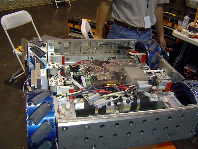